

Page 1

Multi-Touch Panel PC
ACP- 5187
ACP-5187
18.5” Intel
CoreTM i5/ Celeron Processor
Fanless Multi-Touch Panel PC
®
CoreTM i7/
High Brightness
ACP-5187 Manual 2nd Ed
October 2013
Page 2

Multi-Touch Panel PC
ACP- 5187
Copyright Notice
This document is copyrighted, 2013. All rights are reserved. The
original manufacturer reserves the right to make improvements to
the products described in this manual at any time without notice.
No part of this manual may be reproduced, copied, translated, or
transmitted in any form or by any means without the prior written
permission of the original manufacturer. Information provided in this
manual is intended to be accurate and reliable. However, the
original manufacturer assumes no responsibility for its use, nor for
any infringements upon the rights of third parties, which may result
from its use.
The material in this document is for product information only and is
subject to change without notice. While reasonable efforts have
been made in the preparation of this document to assure its
accuracy, AAEON, assumes no liabilities resulting from errors or
omissions in this document, or from the use of the information
contained herein.
AAEON reserves the right to make changes in the product design
without notice to its users.
i
Page 3

Multi-Touch Panel PC
ACP- 5187
Acknowledgments
Intel
Microsoft
®
, CoreTM are registered trademarks of Intel® Corporation.
®
Windows is a registered trademark of Microsoft®
Corporation.
RTL is a trademark of Realtek Semi-Conductor Co., Ltd.
C&T is a trademark of Chips and Technologies, Inc.
UMC is a trademark of United Microelectronics Corporation.
ITE is a trademark of Integrated Technology Express, Inc.
All other product names or trademarks are properties of their
respective owners.
ii
Page 4

Multi-Touch Panel PC
ACP- 5187
Packing List
Before you begin installing your Panel PC, please make sure
that the following items have been shipped:
ACP-5187 Infotainment Multi-Touch Panel PC
Power Adapter x 1
Product DVD
Contains User’s Manual (in PDF format), Drivers and
Utilities
If any of these items are missing or damaged, you should contact your
distributor or sales representative immediately.
iii
Page 5

Multi-Touch Panel PC
ACP- 5187
Safety & Warranty
1. Read these safety instructions carefully.
2. Keep this user's manual for later reference.
3. Disconnect this equipment from any AC outlet before cleaning. Do
not use liquid or spray detergents for cleaning. Use a damp cloth.
4. For pluggable equipment, the power outlet must be installed near
the equipment and must be easily accessible.
5. Keep this equipment away from humidity.
6. Put this equipment on a reliable surface during installation.
Dropping it or letting it fall could cause damage.
7. The openings on the enclosure are for air convection. Protect the
equipment from overheating. DO NOT COVER THE OPENINGS.
8. Make sure the voltage of the power source is correct before
connecting the equipment to the power outlet.
9. Position the power cord so that people cannot step on it. Do not
place anything over the power cord.
10. All cautions and warnings on the equipment should be noted.
11. If the equipment is not used for a long time, disconnect it from the
power source to avoid damage by transient over-voltage.
12. Never pour any liquid into an opening. This could cause fire or
electrical shock.
13. Never open the equipment. For safety reasons, only qualified
service personnel should open the equipment.
iv
Page 6

Multi-Touch Panel PC
ACP- 5187
14. If any of the following situations arises, get the equipment
checked by service personnel:
a. The power cord or plug is damaged.
b. Liquid has penetrated into the equipment.
c. The equipment has been exposed to moisture.
d. The equipment does not work well, or you cannot get it to
work according to the user’s manual.
e. The equipment has been dropped and damaged.
f. The equipment has obvious signs of breakage.
15. DO NOT LEAVE THIS EQUIPMENT IN AN UNCONTROLLED
ENVIRONMENT WHERE THE STORAGE TEMPERATURE IS
BELOW -20° C (-4°F) OR ABOVE 60° C (140° F). IT MAY
DAMAGE THE EQUIPMENT.
16. External equipment intended for connection to signal input/output
or other connectors, shall comply with relevant UL / IEC standard
(e.g. UL 1950 for IT equipment and UL 60601-1 / IEC 60601 series
for systems – shall comply with the standard IEC 60601-1-1,
Safety requirements for medical electrical systems. Equipment
not complying with UL 60601-1 shall be kept outside the patient
environment, as defined in the standard.
17. When the temperature of CPU is higher than 35°C, the frequency
of CPU will be adjusted automatically. For example, if the
temperature of Intel Core i7 is 40°C, the frequency of the CPU will
be between 1.8~1.3 GHz.
Caution:
It may cause the danger of explosion if battery is incorrectly
replaced. Replace only with same or equivalent type
recommended by the manufacturer.
v
Page 7

Multi-Touch Panel PC
ACP- 5187
Classification
1. Degree of production against electric shock: not classified
2. Degree of protection against the ingress of water: IPX1
3. Equipment not suitable for use in the presence of a flammable
anesthetic mixture with air or with oxygen or nitrous oxide.
4. Mode of operation: Continuous
5. Type of protection against electric shock: Class I equipment
vi
Page 8

Multi-Touch Panel PC
ACP- 5187
FCC
This device complies with Part 15 FCC Rules.
Operation is subject to the following two
conditions: (1) this device may not cause
harmful interference, and (2) this device
must accept any interference received
including interference that may cause
undesired operation.
vii
Page 9
Multi-Touch Panel PC
ACP- 5187
Medical equipment with respect to electric
shock, fire and mechanical hazards only in
accordance with UL 60601-1, and
CAN/CSA C22.2 NO. 601.1
Attention, consult ACCOMPANYING
DOCUMENTS.
Ground wire
Protective Ground wire.
Medical equipment with respect to electric
shock, fire and mechanical hazards only in
accordance with UL 60601-1, and
CAN/CSA C22.2 NO. 601.1
Safety Symbol Description
The following safety symbols are further explanations for your
reference.
viii
Page 10

Multi-Touch Panel PC
ACP- 5187
部件名称
有毒有害物质或元素
铅
(Pb)
汞
(Hg) 镉 (Cd)
六价铬
(Cr(VI))
多溴联苯
(PBB)
多溴二苯醚
(PBDE)
印刷电路板
及其电子组件
× ○ ○ ○ ○
○
外部信号
连接器及线材
× ○ ○ ○ ○
○
外壳
× ○ ○ ○ ○
○
中央处理器
与内存
× ○ ○ ○ ○
○
硬盘
× ○ ○ ○ ○ ○ 液晶模块
× ○ ○ ○ ○ ○ 光驱
× ○ ○ ○ ○ ○ 触控模块
× ○ ○ ○ ○ ○ 电源
× ○ ○ ○ ○
○
O:表示该有毒有害物质在该部件所有均质材料中的含量均在
SJ/T 11363-2006 标准规定的限量要求以下。
X:表示该有毒有害物质至少在该部件的某一均质材料中的含量超出
SJ/T 11363-2006 标准规定的限量要求。
备注:
一、此产品所标示之环保使用期限,系指在一般正常使用状况下。
二、上述部件物质中央处理器、内存、硬盘、光驱、触控模块为选购品。
Below Table for China RoHS Requirements
产品中有毒有害物质或元素名称及含量
AAEON Panel PC/ Workstation
ix
Page 11

Multi-Touch Panel PC
ACP- 5187
Contents
Chapter 1 General Information
1.1 Introduction ................................................................ 1-2
1.2 Features .................................................................... 1-3
1.3 Specification .............................................................. 1-4
1.4 General Information................................................... 1-7
Chapter 2 Hardware Installation
2.1 Safety Precautions .................................................... 2-2
2.2 COM2 Pin8 Function Selection (JP8) ....................... 2-3
2.3 Clear CMOS (JP11) .................................................. 2-3
2.4 COM Port 2 Connector (CN11) ................................. 2-3
2.5 COM Port 1 (D-SUB 9) (CN27) ................................. 2-5
2.6 A Quick Tour of the ACP-5187 .................................. 2-6
2.7 2.5” Hard Disk Drive (HDD) Installation .................... 2-9
Chapter 3 AMI BIOS Setup
3.1 System Test and Initialization . ................................. 3-2
3.2 AMI BIOS Setup. ....................................................... 3-3
Chapter 4 Driver Installation
4.1 Installation ................................................................. 4-3
Appendix A Programming the Watchdog Timer
A.1 Programming ......................................................... A-2
A.2 ITE8728F Watchdog Timer Initial Program ........... A-6
x
Page 12

Multi-Touch Panel PC
ACP- 5187
Appendix B I/O Information
B.1 I/O Address Map .................................................... B-2
B.2 Memory Address Map ............................................ B-4
B.3 IRQ Mapping Chart .............................................. B-5
B.4 DMA Channel Assignments ................................... B-5
Appendix C Miscellanea
C.1 General Cleaning Tips .......................................... C-2
C.2 Cleaning Tools ...................................................... C-3
C.3 Scrap Computer Recycling ................................. C-5
C.4 Installing Accessories ........................................... C-6
Appendix D RAID & AHCI Settings
D.1 Setting RAID ......................................................... D-2
D.2 Setting AHCI ......................................................... D-9
xi
Page 13

Multi-Touch Panel PC
ACP- 5187
Chapter
1
General
Information
Chapter 1 General Information 1-1
Page 14

Multi-Touch Panel PC
ACP- 5187
1.1 Introduction
The ACP-5187 is a Multi-Touch Infotainment Panel PC with
superior onboard Intel® Core™ i7/i5/Celeron® processor-based
computer. It is a PC-based system with 18.5” true color TFT LCD
display, integrated multimedia functions make them the perfect
platforms to build comprehensive lifestyle computing applications.
The ACP-5187 includes all the features of a powerful computer into
a slim and attractive chassis. The ACP-5187 has 300 nits TFT
display with 1366 x 768 resolution. This model equips two-point (for
the OS of Windows® XP, Windows® 7 and Windows® Embedded)
Multi-Touch Window design and is easy to clean. Moreover, it is
IPX1 100% water-proof that can be installed in harsh environments.
Its front bezel is IP-65/NEMA4 for auxiliary water-proof protection.
In addition, the ACP-5187 deploys 7H hardness Anti-Scratch
Surface to avoid accidental damage.
The ACP-5187 supports one 2.5” SATA Hard Disk Drive and one
CFast™ slot for the storage functions, and one Mini-Card
expansion. Moreover, it supports Smart Card Reader, RFID, MSR,
Bluetooth, Skype phone, and camera to fulfill the demands of
versatile applications.
Chapter 1 General Information 1-2
Page 15

Multi-Touch Panel PC
ACP- 5187
1.2 Features
18.5” WXGA (1366 x 768) Fanless TFT LCD Display
Easy-To-Clean: Multi-Touch Window Design (Two-Point)
Superior Intel
®
Core™ i7-3610QE/ Core™ i5-3610ME/
Celeron® 1020E Processor
IPx1 100% Water-Proof from the Top Plastic Housing
Anti-Scratch Surface (7H Hardness)
IPX1 WebCam (Optional)
USB x 6, COM x 1. DVI-I x 1, LAN x 2, Mini PCIe Card x 1
Front Access LCD ON/OFF, Brightness UP/DOWN, Volume
UP/DOWN
Chapter 1 General Information 1-3
Page 16

Multi-Touch Panel PC
ACP- 5187
Processor
Onboard Intel® Core™ i7/ Core™ i5 /
Celeron® Processor
System Memory
DDR3 SODIMM x 1, Max. 8 GB (Default
2GB)
LCD / CRT Controller
Integrated graphics in Intel® QM77
I/O Port
USB x 6 (USB2.0 x 2 on side; USB2.0 x
2 and USB3.0 x 2 on bottom)
RS-232 x 1
LAN x 2
Line-out x 1
DVI-I x 1
Power input x 1
2W speaker x 2
ATX power button
Storage Disk Drive
2.5” SATA Hard Disk Drive bay x 1;
CFast™ slot x 1
Expansion
Mini PCIe Card x 1
OS Support
Windows® XP (T/S: Single point), Linux
Fedora (T/S: Multi-point), Windows®7
(T/S: Multi-point), Windows®8
1.3 Specification
System
Chapter 1 General Information 1-4
Page 17

Multi-Touch Panel PC
ACP- 5187
Construction
IPX1 from the top plastic housing
Mounting
VESA 100
Dimension
18.11”(W) x 12.2”(H) x 3.39”(D) (460mm
x 310mm x 86mm)
Carton Dimension
26” x 8.11” x 19.53’’ (661mm x 206mm x
496mm)
Net Weight
15.4 lb (7 kg)
Gross Weight
19.8 lb (9 kg)
Operating Temperature
32oF~104oF (0oC~40oC) (Ambient With
Airflow)
Storage Temperature
-4oF~158oF (-20oC~70oC)
Storage Humidity
5%~90% @ 40oC, non-condensing
Vibration
1 g rms/ 5-500Hz/ Random Operation
(HDD)
Shock
20 G peak acceleration (11 msec.
duration) (HDD)
EMC
CE/FCC Class A
DC Input 84W
DC 12V, with AC power adapter with
lock
Mechanical
Environmental
Power Supply
Chapter 1 General Information 1-5
Page 18

Multi-Touch Panel PC
ACP- 5187
Display Type
18.5” TFT-LCD, CCFL
Max. Resolution
1366 x 768
Max. Colors
16.7 M colors (6/8-bit for R, G, B)
Luminance (cd/m
2
)
300 cd/m2
Contrast Ratio
1000:1
Viewing Angle
85º (H), 80º (V)
Backlight MTBF (Hours)
50,000
Type
Projected Capacitive Multi-Touch (Two
points)
Resolution
2048x2048
Light Transmission
>90%
LCD
Touchscreen
Chapter 1 General Information 1-6
Page 19
Multi-Touch Panel PC
ACP- 5187
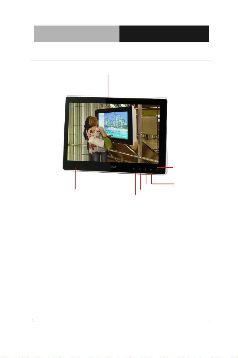
1.3M Camera (Optional)
RFID (Optional)
Brightness-
Volume-
Brightness+
Volume+
LCD On/Off
1.4 General Information
Chapter 1 General Information 1-7
Page 20
Multi-Touch Panel PC
ACP- 5187
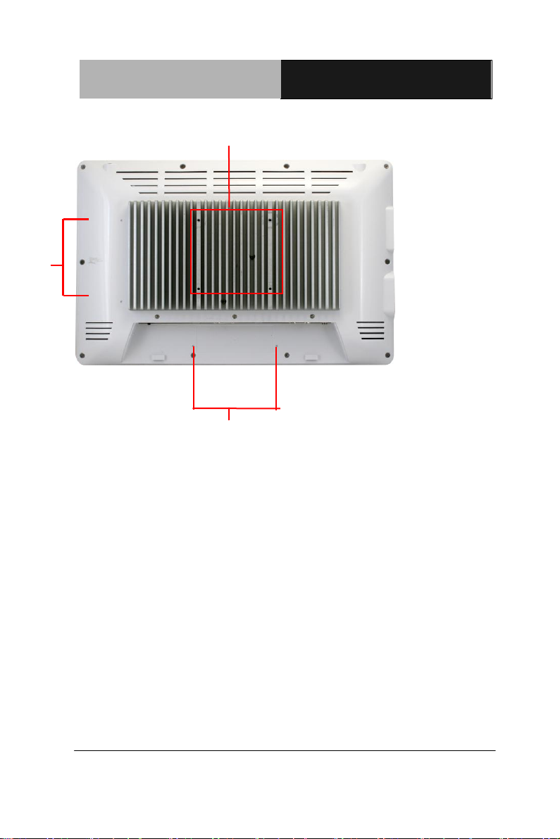
Mounting
Holes
VESA 100
Mounting
Holes
Chapter 1 General Information 1-8
Page 21
Multi-Touch Panel PC
ACP- 5187
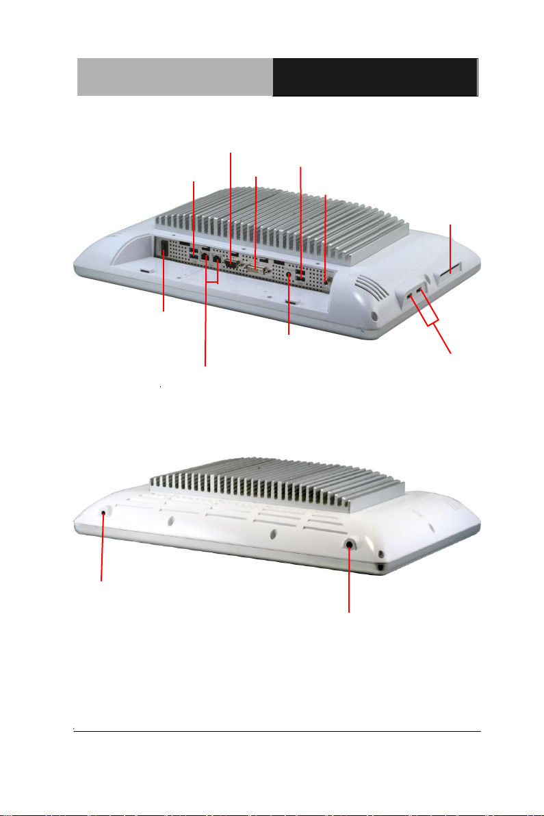
USB x 2
Power Input
Antenna
(Optional)
USB x 2
LAN x 2
Antenna (Optional)
Power Switch
Smart Card
Reader
(Optional)
RS-232
Line-out
DVI-I
USB x 2
Chapter 1 General Information 1-9
Page 22

Multi-Touch Panel PC ACP-5187
Chapter
2
H
Chapter 2 Hardware Installation 2-1
ardware
Inst
allation
Page 23
Multi-Touch Panel PC ACP-5187
2.1 Safety Precautions
Always completely disconnect the power cord
from your board whenever you are working on
it. Do not make connections while the power is
on, because a sudden rush of power can
damage sensitive electronic components.
Always ground yourself to remove any static
charge before touching the board. Modern
electronic devices are very sensitive to static
electric charges. Use a grounding wrist strap at
all times. Place all electronic components on a
static-dissipative surface or in a static-shielded
bag when they are not in the chassis
Chapter 2 Hardware Installation 2-2
Page 24
Multi-Touch Panel PC ACP-5187
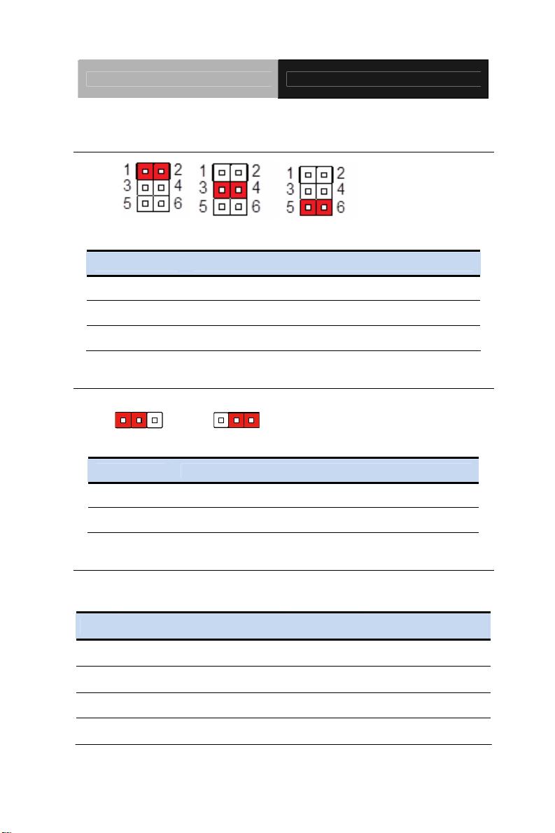
2.2 COM2 Pin8 Function Selection (JP8)
+12V Ring +5V
JP8 Function 1-2 +12V 3-4 Ring (Default) 5-6 +5V
2.3 Clear CMOS (JP11)
123
Normal Clear CMOS
JP11 Function
1-2 Normal (Default)
2-3 Clear CMOS
123
2.4 COM Port 2 Connector (CN11)
RS-232
Pin Pin Name Signal T ype Signal Level
1 DCD IN
2 DSR IN
3 RX IN
4 RTS OUT ±9V
Chapter 2 Hardware Installation 2-3
Page 25

Multi-Touch Panel PC ACP-5187
5 TX OUT ±9V
6 CTS IN
7 DTR OUT ±9V
8 RI/+5V/+12V IN/ PWR +5V/+12V
9 GND GND
RS-422
Pin Pin Name Signal T ype Signal Level
1 RS422_TX- OUT ±5V
2 NC
3 RS422_RX+ IN
4 NC
5 RS422_TX+ OUT ±5V
6 NC
7 RS422_RX- IN
8 NC/+5V/+12V PWR +5V/+12V
9 GND GND
RS-485
Pin Pin Name Signal T ype Signal Level
1 RS485_D- I/O ±5V
2 NC
3 NC
4 NC
5 RS485_D+ I/O ±5V
Chapter 2 Hardware Installation 2-4
Page 26
Multi-Touch Panel PC ACP-5187
6 NC
7 NC
8 NC/+5V/+12V PWR +5V/+12V
9 GND GND
Note: COM2 RS-232/422/485 can be set by BIOS setting. Default is
RS-232. Pin 8 function can be set by JP8.
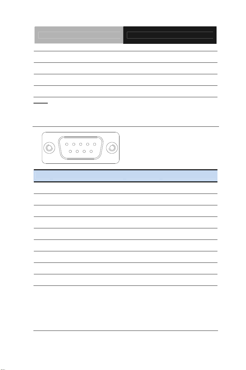
2.5 COM Port 1 (D-SUB 9) (CN27)
15
69
Pin Pin Name Signal T ype Signal Level
1 DCD IN
2 RX IN
3 TX OUT ±9V
4 DTR OUT ±9V
5 GND GND
6 DSR IN
7 RTS OUT ±9V
8 CTS IN
9 RI IN
Chapter 2 Hardware Installation 2-5
Page 27
Multi-Touch Panel PC ACP-5187
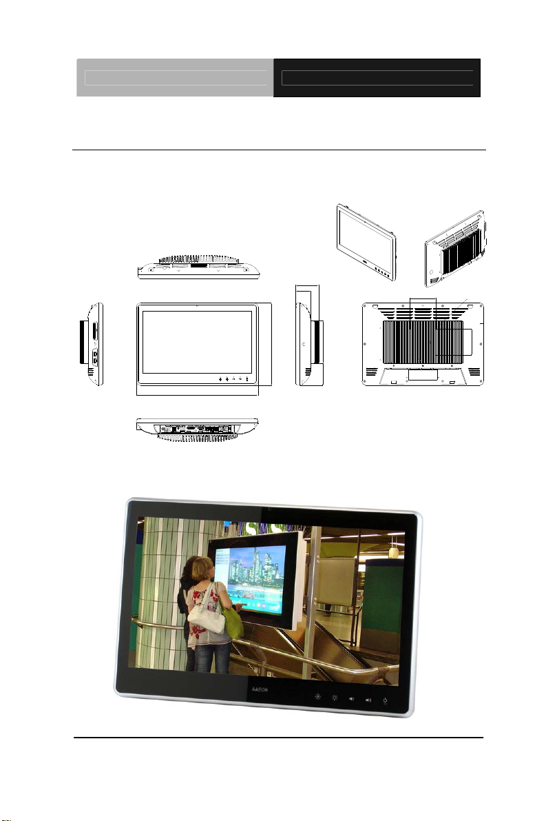
2.6 A Quick Tour of the ACP-5187
Mechanical Drawing
ACP- 5 187
Unit s :m m
86.4
56.0
100.0
VESA 100
Front
460.0
310.0
160.0
82.6
100.0
Chapter 2 Hardware Installation 2-6
Page 28
Multi-Touch Panel PC ACP-5187
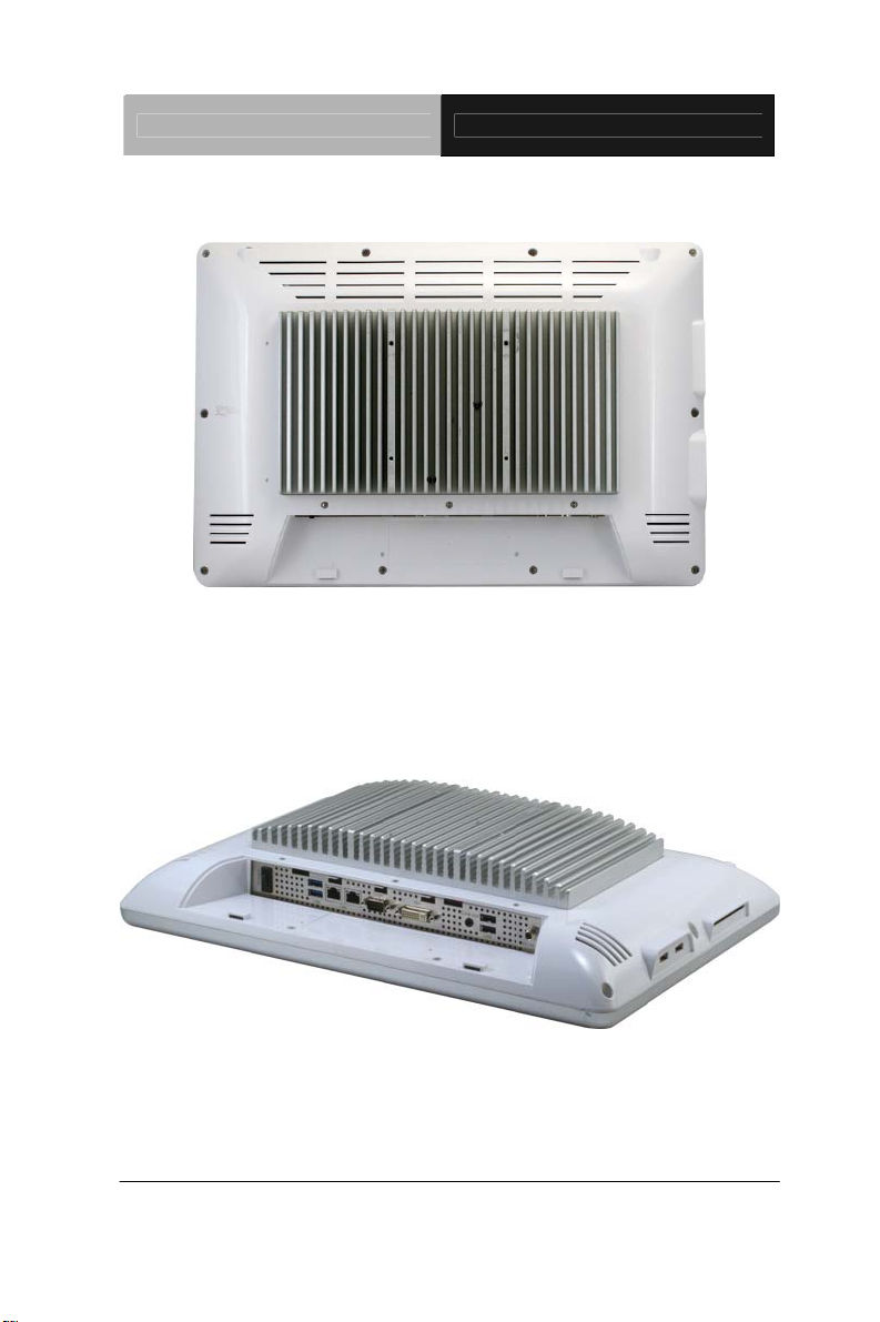
Rear
I/O
Chapter 2 Hardware Installation 2-7
Page 29
Multi-Touch Panel PC ACP-5187
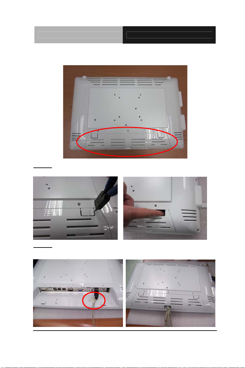
Cable Cover (Optional)
Note 1: You may turn on the power by cutting and destroying the protective
cover as it shows below.
Note 2: The “Anti-Drop Kit” can help on preventing the cable drop from the
connector
Chapter 2 Hardware Installation 2-8
Page 30
Multi-Touch Panel PC ACP-5187
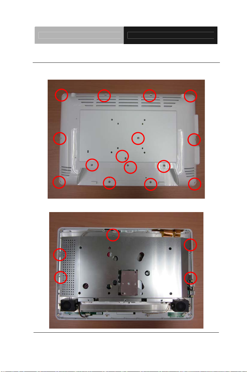
2.7 2.5” Hard Disk Drive (HDD) Installation
Step 1: Unscrew the rear cover screws (15 screws)
Step 2: Remove EMI Cover (5 screws)
Chapter 2 Hardware Installation 2-9
Page 31

Multi-Touch Panel PC ACP-5187
Step 3: Remove HDD Bracket (4 screws)
Step 4: Get the HDD and HDD Bracket ready
Chapter 2 Hardware Installation 2-10
Page 32

Multi-Touch Panel PC ACP-5187
Step 5: Fasten the four screws to fix HDD Bracket and HDD
Step 6: Connect the SATA and power cables to the HDD and fasten the
four screws to fix the HDD Bracket
Chapter 2 Hardware Installation 2-11
Page 33

Multi-Touch Panel PC
ACP- 5187
Chapter
3
AMI
BIOS Setup
Chapter 3 AMI BIOS Setup 3-1
Page 34

Multi-Touch Panel PC
ACP- 5187
3.1 System Test and Iinitialization
These routines test and initialize board hardware. If the routines
encounter an error during the tests, you will either hear a few short
beeps or see an error message on the screen. There are two kinds
of errors: fatal and non-fatal. The system can usually continue the
boot up sequence with non-fatal errors.
System configuration verification
These routines check the current system configuration stored in the
CMOS memory and BIOS NVRAM. If system configuration is not
found or system configuration data error is detected, system will
load optimized default and re-boot with this default system
configuration automatically.
There are four situations in which you will need to setup system
configuration:
1. You are starting your system for the first time
2. You have changed the hardware attached to your system
3. The system configuration is reset by Clear-CMOS jumper
4. The CMOS memory has lost power and the configuration
information has been erased.
The ACP-5187 CMOS memory has an integral lithium battery
backup for data retention. However, you will need to replace the
complete unit when it finally runs down.
Chapter 3 AMI BIOS Setup 3-2
Page 35

Multi-Touch Panel PC
ACP- 5187
3.2 AMI BIOS Setup
AMI BIOS ROM has a built-in Setup program that allows users to
modify the basic system configuration. This type of information is
stored in battery-backed CMOS RAM and BIOS NVRAM so that it
retains the Setup information when the power is turned off.
Entering Setup
Power on the computer and press <Del>or <F2> immediately. This
will allow you to enter Setup.
Main
Set the date, use tab to switch between date elements.
Advanced
Enable disable boot option for legacy network devices.
Chipset
Host bridge parameters.
Boot
Enables/disable quiet boot option.
Security
Set setup administrator password.
Save & Exit
Exit system setup after saving the changes.
Chapter 3 AMI BIOS Setup 3-3
Page 36

Multi-Touch Panel PC
ACP- 5187
System Date
Day MM:DD:YYYY
Change the month, year and century. The „Day‟ is changed automatically.
System Time
HH : MM : SS
Change the clock of the system.
Setup Menu
Setup submenu: Main
Options summary: (default setting)
Chapter 3 AMI BIOS Setup 3-4
Page 37

Multi-Touch Panel PC
ACP- 5187
ACPI Settings
System ACPI Parameters
Trusted Computing
Trusted Computing Settings
CPU Configuration
CPU Configuration Parameters
SATA Configuration
SATA Device Options Settings
Setup submenu: Advanced
Options summary: (default setting)
Chapter 3 AMI BIOS Setup 3-5
Page 38

Multi-Touch Panel PC
ACP- 5187
Intel TXT(LT)
Configuration
Intel Trusted Execution Technology
AMT Configuration
AMT Configuration Parameters
USB Configuration
USB Configuration Parameters
H/W Monitor
Monitor hardware status
Super IO Configuration
Super IO Configuration Parameters
Chapter 3 AMI BIOS Setup 3-6
Page 39

Multi-Touch Panel PC
ACP- 5187
Enable Hibernation
Enabled
Disabled
Enabled or disabled hibernate (OS/S4 Sleep State).
ACPI Sleep State
Suspend Disabled
S1 only(CPU Stop Clock)
S3 only(Suspend to RAM)
Auto
Select the ACPI state used for System Suspend
Wake on Ring
Enabled
ACPI Settings
Options summary: (default setting)
Chapter 3 AMI BIOS Setup 3-7
Page 40

Multi-Touch Panel PC
ACP- 5187
Disabled
Enabled or disabled wake on ring function.
Wake system with
Fixed Time
Disabled
Enabled
Enable or disable System wake on alarm event. Wake up time is setting by
following settings.
Wake up day
0-31
Wake up hour
0-23
RTC Wake Settings
Options summary: (default setting)
Chapter 3 AMI BIOS Setup 3-8
Page 41

Multi-Touch Panel PC
ACP- 5187
Wake up minute
0-59
Wake up second
0-59
Wake system with
Dynamic Time
Disabled
Enabled
Enable or disable System wake on alarm event. Wake up time is current
time + Increase minutes.
Wake up minute
increase
1-5
Trusted Computing
Chapter 3 AMI BIOS Setup 3-9
Page 42

Multi-Touch Panel PC
ACP- 5187
Security Device Support
Disabled
Enabled
En/Disable TPM support.
TPM State
Disabled
Enabled
En/Disable TPM functionality.
Pending TPM Operation
None
Enable Take Ownership
Disable Take
Ownership
TPM Clear
Select one-time TPM operation. Item value returns to „None‟ after next
POST.
Options summary: (default setting)
Chapter 3 AMI BIOS Setup 3-10
Page 43

Multi-Touch Panel PC
ACP- 5187
Hyper-Threading
Disabled
Enabled
En/Disable CPU Hyper-Threading function
Active Processor Cores
ALL
1 to Max CPU cores
Number of CPU cores to be active.
Limit CPUID Maximum
Disabled
Enabled
Disabled for Windows XP
Execute Disable Bit
Disabled
CPU Configuration
Options summary: (default setting)
Chapter 3 AMI BIOS Setup 3-11
Page 44

Multi-Touch Panel PC
ACP- 5187
Enabled
En/Disable XD bit for supporting OS
Intel Virtualization
Technology
Disabled
Enabled
En/Disable Intel VT-x function
EIST
Disabled
Enabled
En/Disable Intel SpeedStep
Turbo Mode
Disabled
Enabled
En/Disable Intel Turbo Mode
SATA Configuration
Chapter 3 AMI BIOS Setup 3-12
Page 45

Multi-Touch Panel PC
ACP- 5187
SATA Controller(s)
Disabled
Enabled
En/Disable SATA controller
Configure SATA as
IDE AHCI
RAID
Available for QM77 Sku
Configure SATA controller operating as IDE/AHCI/RAID mode.
Port 1/Port 2/CFast
Slot
Disabled
Enabled
En/Disable the selected port.
Hot Plug
Disabled
Enabled
En/Disable Hot Plug feature for specified port.
Options summary: (default setting)
Chapter 3 AMI BIOS Setup 3-13
Page 46

Multi-Touch Panel PC
ACP- 5187
Intel TXT(LT) Support
Disabled
Enabled
En/Disable Intel TXT function. This function only can be enabled/disabled if
SMX, VT-x and VT-d support are enabled prior to it.
Intel TXT(LT) Configuration
Options summary: (default setting)
Chapter 3 AMI BIOS Setup 3-14
Page 47

Multi-Touch Panel PC
ACP- 5187
Intel AMT
Enabled
Disabled
En/Disable Intel® Active Management Technology BIOS Extension.
Note: iAMT H/W is always enabled. This option just controls the BIOS
extension execution. If enabled, this requires additional firmware in the SPI
device
Un-Configure ME
Enabled
Disabled
OEMFlag Bit 15: Un-Configure ME without password
AMT Configuration
Options summary: (default setting)
Chapter 3 AMI BIOS Setup 3-15
Page 48

Multi-Touch Panel PC
ACP- 5187
Legacy USB Support
Enabled
Disabled
Auto
Enables BIOS Support for Legacy USB Support. When enabled, USB can
be functional in legacy environment like DOS. AUTO option disables legacy
support if no USB devices are connected. DISABLE option will keep USB
devices available only for EFI application
USB3.0 Support
Enabled
Disabled
USB Configuration
Options summary: (default setting)
Chapter 3 AMI BIOS Setup 3-16
Page 49

Multi-Touch Panel PC
ACP- 5187
Enables BIOS Support for USB3.0 (XHCI). When disabled, PCH USB3.0
controller will also be disabled.
Device Name
(Emulation Type)
Auto
Floppy
Forced FDD
Hard Disk
CD-ROM
If Auto. USB devices less than 530MB will be emulated as Floppy and
remaining as Floppy and remaining as hard drive. Forced FDD option can
be used to force a HDD formatted drive to boot as FDD(Ex. ZIP drive)
H/W Monitor
Chapter 3 AMI BIOS Setup 3-17
Page 50

Multi-Touch Panel PC
ACP- 5187
Serial Port 1/2
Configuration
Set Parameters of Serial Port 1/2
Restore AC Power Loss
Power Off
Power On
Last State
Select AC power state when power is re-applied after a power failure.
EuP Power Control
Disabled
Enabled
Super IO Configuration
Options summary: (default setting)
Chapter 3 AMI BIOS Setup 3-18
Page 51

Multi-Touch Panel PC
ACP- 5187
Configure Energy-using Product(EuP) Power Control.
Serial Port
Disabled
Enabled
En/Disable specified serial port.
Change Settings
Auto
IO=3F8h; IRQ=4;
IO=3F8h;
IRQ=3,4,5,7,10,11,12;
Serial Port 1 Configuration
Options summary: (default setting)
Chapter 3 AMI BIOS Setup 3-19
Page 52

Multi-Touch Panel PC
ACP- 5187
IO=2F8h;
IRQ=3,4,5,7,10,11,12;
IO=3E8h;
IRQ=3,4,5,7,10,11,12;
IO=2E8h;
IRQ=3,4,5,7,10,11,12;
Select a resource setting for Super IO device.
Serial Port
Disabled
Enabled
Serial Port 2 Configuration
Options summary: (default setting)
Chapter 3 AMI BIOS Setup 3-20
Page 53

Multi-Touch Panel PC
ACP- 5187
En/Disable specified serial port.
Change Settings
Auto
IO=2F8h; IRQ=3;
IO=3F8h;
IRQ=3,4,5,7,10,11,12;
IO=2F8h;
IRQ=3,4,5,7,10,11,12;
IO=3E8h;
IRQ=3,4,5,7,10,11,12;
IO=2E8h;
IRQ=3,4,5,7,10,11,12;
Select a resource setting for Super IO device.
Device Type
RS232
RS422
RS485
Configure COM2 operated as RS232, RS422 or RS485.
Chapter 3 AMI BIOS Setup 3-21
Page 54

Multi-Touch Panel PC
ACP- 5187
Onboard Device
Configure Onboard Devices
PCI-IO Configuration
South Bridge Parameters
Memory Configuration
Memory Parameters
Graphic Configuration
Graphic Parameters
Setup submenu: Chipset
Options summary: (default setting)
Chapter 3 AMI BIOS Setup 3-22
Page 55

Multi-Touch Panel PC
ACP- 5187
Onboard HD Audio
Disabled
Enabled
Auto
En/Disabled HD Audio controller.
HD Audio Internal
HDMI Codec
Enabled
Disabled
En/Disabled internal HDMI codec for HD Audio.
Intel LAN Controller
Enabled
Disabled
Onboard Device
Options summary: (default setting)
Chapter 3 AMI BIOS Setup 3-23
Page 56

Multi-Touch Panel PC
ACP- 5187
En/Disabled Intel i82579 NIC
Realtek LAN Controller
Enabled
Disabled
En/Disabled Realtek RTL8111E NIC
Power Mode
ATX Type
Select the power type used on the system
PCIe MiniCard Slot
Disabled
Enabled
Control the PCI Express Root Port.
PCH-IO Configuration
Options summary: (default setting)
Chapter 3 AMI BIOS Setup 3-24
Page 57

Multi-Touch Panel PC
ACP- 5187
PCIe Speed
Auto
Gen1
Gen2
Select PCI Express port speed. Some PCIe carsd must set to Gen1 for
operation.
DIMM Profile
Default DIMM profile
XMP Profile 1
XMP Profile 2
Select DIMM timing profile that should be used
Memory Configuration
Options summary: (default setting)
Chapter 3 AMI BIOS Setup 3-25
Page 58

Multi-Touch Panel PC
ACP- 5187
Memory Frequency
Limiter
Auto
1067
1333
1600
Maximum Memory Frequency Selections in Mhz.
Max TOLUD
Dynamic
1 GB
1.25 GB
1.5 GB
1.75 GB
2 GB
2.25 GB
2.5 GB
2.75 GB
3 GB
3.25 GB
Maximum Value of TOLUD. Dynamic assignment would adjust TOLUD
automatically based on largest MMIO length of install graphic controller.
Chapter 3 AMI BIOS Setup 3-26
Page 59

Multi-Touch Panel PC
ACP- 5187
Primary Display
Auto
IGFX
PCI
Select graphic adapters to boot
Internal Graphics
Auto
Disabled
Enabled
En/Disabled internal graphics device
GTT Size
1MB
Graphic Configuration
Options summary: (default setting)
Chapter 3 AMI BIOS Setup 3-27
Page 60

Multi-Touch Panel PC
ACP- 5187
2MB
Select the GTT Size
Aperture Size
128MB
256MB
512MB
Select the Aperture Size
DVMT Pre-Allocated
64MB
32MB~1024MB
Select DVMT 5.0 Pre-Allocated (Fixed) Graphics Memory size used by the
Internal Graphics Device.
DVMT Total Gfx Mem
128MB
256MB
Max
Select DVMT 5.0 Total Graphic Memory size used by the Internal Graphics
Device.
Chapter 3 AMI BIOS Setup 3-28
Page 61

Multi-Touch Panel PC
ACP- 5187
Primary IGFX Boot
Display
Auto Detect
DVI-A
LVDS1
DVI-D
Select Primary IGFX boot display device
Note: LVDS1 is the default main display device when this item set to “Auto
Detect” and LVDS1 enabled.
In this case, DVI will not display under DOS environment unless user set this
item to DVI manually.
LCD Control
Options summary: (default setting)
Chapter 3 AMI BIOS Setup 3-29
Page 62

Multi-Touch Panel PC
ACP- 5187
LVDS1(Internal)
Enabled
Enable Internal LVDS
LVDS1 Panel Type
1366x768 24-Bit
1366x768 24-Bit resolution.
Chapter 3 AMI BIOS Setup 3-30
Page 63

Multi-Touch Panel PC
ACP- 5187
Quiet Boot
Disabled
Enabled
En/Disable showing boot logo.
Launch I82579LM/
RTL8111E PXE
OpROM
Disabled
Enabled
En/Disable PXE boot for I82579LM/RTL8111E LAN
Setup submenu: Boot
Options summary: (default setting)
Chapter 3 AMI BIOS Setup 3-31
Page 64

Multi-Touch Panel PC
ACP- 5187
Boot Option #X/
XXXX Drive BBS
Priorities
The order of boot priorities.
Boot Option #x
Disabled
Device name
Sets the system boot order
BBS Priorities
Options summary: (default setting)
Chapter 3 AMI BIOS Setup 3-32
Page 65

Multi-Touch Panel PC
ACP- 5187
Administrator
Password/
User Password
Not set
Setup submenu: Security
Options summary: (default setting)
Chapter 3 AMI BIOS Setup 3-33
Page 66

Multi-Touch Panel PC
ACP- 5187
You can install a Supervisor password, and if you install a supervisor
password, you can then install a user password. A user password does not
provide access to many of the features in the Setup utility.
Install the Password:
Press Enter on this item, a dialog box appears which lets you enter a
password. You can enter no more than six letters or numbers. Press Enter
after you have typed in the password. A second dialog box asks you to retype
the password for confirmation. Press Enter after you have retyped it correctly.
The password is required at boot time, or when the user enters the Setup
utility.
Removing the Password:
Highlight this item and type in the current password. At the next dialog box
press Enter to disable password protection.
Chapter 3 AMI BIOS Setup 3-34
Page 67

Multi-Touch Panel PC
ACP- 5187
Save Changes and Reset
Reset the system after saving the changes
Discard Changes and Reset
Reset system setup without saving any changes
Restore Defaults
Restore/Load Default values for all the setup options.
Save as User Defaults
Save the changes done so far as User Defaults
Restore User Defaults
Restore the User Defaults to all the setup options
Setup submenu: Exit
Options summary: (default setting)
Chapter 3 AMI BIOS Setup 3-35
Page 68

Multi-Touch Panel PC ACP-5187
Chapter
4
Driver
Inst
Chapter 4 Driver Installation 4-1
allation
Page 69

Multi-Touch Panel PC ACP-5187
The ACP-5187 comes with an AutoRun DVD-ROM that contains all
drivers and utilities that can help you to install the driver
automatically.
Insert the driver DVD, the driver DVD-title will auto start and show
the installation guide. If not, please follow the sequence below to
install the drivers.
Follow the sequence below to install the drivers:
Step 1 – Install Chipset Driver
Step 2 – Install VGA Driver
Step 3 – Install LAN1 Driver (Intel
Step 4 – Install LAN2 Driver (Realtek LAN Chip)
Step 5 – Install Audio Driver
Step 6 – Install ME Driver
®
LAN Chip)
Step 7 – Install RAID & AHCI Driver
Step 8 – Install TPM Driver
Step 9 – Install Touch Driver
Step 10 – Install USB3.0 Driver (Windows
®
7 only)
Please read instructions below for further detailed installations.
Chapter 4 Driver Installation 4-2
Page 70

Multi-Touch Panel PC ACP-5187
4.1 Installation:
Insert the ACP-5187 DVD-ROM into the DVD-ROM drive. And
install the drivers from Step 1 to Step 10 in order.
Step 1 – Install Chipset Driver
1. Click on the STEP 1-CHIPSET folder and select the OS
folder your system is
2. Double click on the infinst_autol.exe file located in each
OS folder
3. Follow the instructions that the window shows
4. The system will help you install the driver automatically
Step 2 – Install VGA Driver
1. Click on the STEP2-VGA folder and select the OS folder
your system is
2. Double click on the Setup.exe file located in each OS
folder
3. Follow the instructions that the window shows
4. The system will help you install the driver automatically
Note 1:
This motherboard supports VGA and LVDS displa y devices. In
Single Display mode, use the hot keys to switch between VGA to
LVDS device or vice versa. By default, press
<Ctrl>+<Alt>+<F1> to switch to VGA device and press
<Ctrl>+<Alt>+<F3> to switch to LVDS device.
Before removing the current display device, connect the display
device that you want to use, and then press the hot keys to
switch to that device.
Chapter 4 Driver Installation 4-3
Page 71

Multi-Touch Panel PC ACP-5187
Note 2: If the OS is Windows® XP, you have to install the driver of
dotNet Framework first. Simply click on dotnetfx35.exe located in
dotNet Framwork folder.
Step 3 –Install LAN 1 Driver (Intel® LAN Chip)
1. Click on the STEP3-LAN1 folder and select the OS
folder your system is
2. Double click on the .exe file located in each OS
folder
3. Follow the instructions that the window shows
4. The system will help you install the driver automatically
Step 4 –Install LAN2 Driver (Realtek LAN Chip)
1. Click on the STEP4-LAN2 folder and select the OS
folder your system is
2. Double click on the setup.exe file located in each OS folder
3. Follow the instructions that the window shows
4. The system will help you install the driver automatically
Step 5 –Install Audio Driver
1. Click on the STEP5-AUDIO folder and select the OS folder
your system is
2. Double click on the .exe file located in each OS
folder
3. Follow the instructions that the window shows
4. The system will help you install the driver automatically
Chapter 4 Driver Installation 4-4
Page 72

Multi-Touch Panel PC ACP-5187
Step 6 – Install ME Driver
Click on the STEP6-ME SW folder and select the OS folder
1.
your system is
2. Double click on the Setup.exe file located in each OS
folder
3. Follow the instructions that the window shows
4. The system will help you install the driver automatically
Step 7 – Install RAID & AHCI Driver
Please refer to the Appendix D RAID & AHCI Settings
Step 8 – Install TPM Driver
1. Click on the STEP8-TPM folder and select the OS
folder your system is
2. Double click on the Setup.exe file located in each OS
folder
3. Follow the instructions that the window shows
4. The system will help you install the driver automatically
Step 9 –Install Touch Driver
1. Click on the STEP9-TOUCH folder and select the folder of
WINXP_32
2. Double click on the ModifyDBArea
3. Follow the instructions that the window shows
4. The system will help you install the driver automatically
Chapter 4 Driver Installation 4-5
Page 73

Multi-Touch Panel PC ACP-5187
Step 10 –Install USB3.0 Driver
1. Click on the STEP10-USB3.0 folder and select the OS
folder your system is
2. Double click on the Setup.exe file located in
each OS folder
3. Follow the instructions that the window shows
4. The system will help you install the driver automatically
Chapter 4 Driver Installation 4-6
Page 74

Multi-Touch Panel PC ACP-5187
A
Appendix
Programming the
atchdog Timer
W
Appendix A Programming the Watchdog Timer A-1
Page 75

Multi-Touch Panel PC ACP-5187
A.1 Programming
ACP-5187 utilizes ITE IT8728F chipset as its watchdog timer
controller.
Below are the procedures to complete its configuration and the
AAEON intial watchdog timer program is also attached based on
which you can develop customized program to fit your application.
Configuring Sequence Description
After the hardware reset or power-on reset, the ITE 8728F enters
the normal mode with all logical devices disabled except KBC. The
initial state (enable bit ) of this logical device (KBC) is determined
by the state of pin 121 (DTR1#) at the falling edge of the system
reset during power-on reset.
Appendix A Programming the Watchdog Timer A-2
Page 76

Multi-Touch Panel PC ACP-5187
There are three steps to complete the configuration setup: (1) Enter
the MB PnP Mode; (2) Modify the data of configuration registers; (3)
Exit the MB PnP Mode. Undesired result may occur if the MB PnP
Mode is not exited normally.
(1) Enter the MB PnP Mode
To enter the MB PnP Mode, four special I/O write operations are to
be performed during Wait for Key state. To ensure the initial state of
the key-check logic, it is necessary to perform four write ope rations
to the Special Address port (2EH). Two different enter keys are
provided to select configuration ports (2Eh/2Fh) of the next step.
(2) Modify the Data of the Registers
All configuration registers can be accessed after entering the MB
PnP Mode. Before accessing a selected register, the content of
Index 07h must be changed to the LDN to which the register
belongs, except some Global registers.
(3) Exit the MB PnP Mode
Set bit 1 of the configure control register (Index=02h) to 1 to exit the
MB PnP Mode.
Appendix A Programming the Watchdog Timer A-3
Page 77

Multi-Touch Panel PC ACP-5187
WatchDog Timer Configuration Registers
Configure Control (Index=02h)
This register is write only. Its values are not sticky; that is to say, a
hardware reset will automatically clear the bits, and does not
require the software to clear them.
Appendix A Programming the Watchdog Timer A-4
Page 78

Multi-Touch Panel PC ACP-5187
WatchDog Timer Control Register (Index=71h, Default=00h)
WatchDog Timer Configuration Register (Index=72h,
Default=00h)
WatchDog Timer Time-out Value Register (Index=73h,
Default=00h)
Appendix A Programming the Watchdog Timer A-5
Page 79

Multi-Touch Panel PC ACP-5187
A.2 ITE8728F Watchdog Timer Initial Program
.MODEL SMALL
.CODE
Main:
CALL Enter_Configuration_mode
CALL Check_Chip
mov cl, 7
call Set_Logic_Device
;time setting
mov cl, 10 ; 10 Sec
dec al
Watch_Dog_Setting:
;Timer setting
mov al, cl
mov cl, 73h
call Superio_Set_Reg
;Clear by keyboard or mouse interrupt
mov al, 0f0h
mov cl, 71h
call Superio_Set_Reg
;unit is second.
mov al, 0C0H
mov cl, 72h
call Superio_Set_Reg
Appendix A Programming the Watchdog Timer A-6
Page 80

Multi-Touch Panel PC ACP-5187
; game port enable
mov cl, 9
call Set_Logic_Device
Initial_OK:
CALL Exit_Configuration_mode
MOV AH,4Ch
INT 21h
Enter_Configuration_Mode PROC NEAR
MOV SI,WORD PTR CS:[Offset Cfg_Port]
MOV DX,02Eh
MOV CX,04h
Init_1:
MOV AL,BYTE PTR CS:[SI]
OUT DX,AL
INC SI
LOOP Init_1
RET
Enter_Configuration_Mode ENDP
Exit_Configuration_Mode PROC NEAR
MOV AX,0202h
CALL Write_Configuration_Data
Appendix A Programming the Watchdog Timer A-7
Page 81

Multi-Touch Panel PC ACP-5187
RET
Exit_Configuration_Mode ENDP
Check_Chip PROC NEAR
MOV AL,20h
CALL Read_Configuration_Data
CMP AL,87h
JNE Not_Initial
MOV AL,21h
CALL Read_Configuration_Data
CMP AL,12h
JNE Not_Initial
Need_Initial:
STC
RET
Not_Initial:
CLC
RET
Check_Chip ENDP
Read_Configuration_Data PROC NEAR
MOV DX,WORD PTR CS:[Cfg_Port+04h]
OUT DX,AL
Appendix A Programming the Watchdog Timer A-8
Page 82

Multi-Touch Panel PC ACP-5187
MOV DX,WORD PTR CS:[Cfg_Port+06h]
IN AL,DX
RET
Read_Configuration_Data ENDP
Write_Configuration_Data PROC NEAR
MOV DX,WORD PTR CS:[Cfg_Port+04h]
OUT DX,AL
XCHG AL,AH
MOV DX,WORD PTR CS:[Cfg_Port+06h]
OUT DX,AL
RET
Write_Configuration_Data ENDP
Superio_Set_Reg proc near
push ax
MOV DX,WORD PTR CS:[Cfg_Port+04h]
mov al,cl
out dx,al
pop ax
inc dx
out dx,al
ret
Superio_Set_Reg endp.Set_Logic_Device proc near
Set_Logic_Device proc near
Appendix A Programming the Watchdog Timer A-9
Page 83

Multi-Touch Panel PC ACP-5187
push ax
push cx
xchg al,cl
mov cl,07h
call Superio_Set_Reg
pop cx
pop ax
ret
Set_Logic_Device endp
;Select 02Eh->Index Port, 02Fh->Data Port
Cfg_Port DB 087h,001h,055h,055h
DW 02Eh,02Fh
END Main
Note: Interrupt level mapping
0Fh-Dh: not valid
0Ch: IRQ12
.
.
03h: IRQ3
02h: not valid
01h: IRQ1
00h: no interrupt selected
Appendix A Programming the Watchdog Timer A-10
Page 84

Multi-Touch Panel PC ACP-5187
Appendix
B
I/O Information
Appendix B I/O Information B-1
Page 85

Multi-Touch Panel PC ACP-5187
B.1 I/O Address Map
Appendix B I/O Information B-2
Page 86

Multi-Touch Panel PC ACP-5187
Appendix B I/O Information B-3
Page 87

Multi-Touch Panel PC ACP-5187
B.2 Memory Address Map
Appendix B I/O Information B-4
Page 88

Multi-Touch Panel PC ACP-5187
B.3 IRQ Mapping Chart
B.4 DMA Channel Assignments
Appendix B I/O Information B-5
Page 89

Multi-Touch Panel PC ACP-5187
A ppendix
C
Miscel
Appendix C Miscellanea C-1
lanea
Page 90

Multi-Touch Panel PC ACP-5187
C.1 General Cleaning Tips
You may need the following precautions before you begin to clean
the computer. When you clean any single part or component for the
computer, please read and understand the details below fully.
1. Never spray or squirt the liquids directly onto any computer
component. If you need to clean the device, please rub it
with a piece of dry cloth.
2. Be cautious of the tiny removable components when you
use a vacuum cleaner to absorb the dirt on the floor.
3. Turn the system off before you start to clean up the
component or computer.
4. Never drop the components inside the computer or get
circuit board damp or wet.
5. Be cautious of all kinds of cleaning solvents or chemicals
when you use it for the sake of cleaning. Some individuals
may be allergic to the ingredients.
6. Try not to put any food, drinks or cigarettes around the
computer.
Appendix C Miscellanea C-2
Page 91

Multi-Touch Panel PC ACP-5187
C.2 Cleaning tools
Although many companies have created products to help improve
the process of cleaning your computer and peripherals users can
also use household items to clean their computers and peripherals.
Below is a listing of items you may need or want to use while
cleaning your computer or computer peripherals.
Keep in mind that some components in your computer may only be
able to be cleaned using a product designed for cleaning that
component, if this is the case it will be mentioned in the cleaning
tips.
Cloth - A piece of cloth is the best tool to use when rubbing
up a component. Although paper towels or tissues can be
used on most hardware as well, we still recommend you to
rub it with a piece of cloth.
W ater or rubbing alcohol – You may moisten a piece of
cloth a bit with some water or rubbing alcohol and rub it on
the computer. Unknown solvents may be harmful to the
plastics parts.
Vacuum cleaner - Absorb the dust, dirt, hair, cigarette
particles, and other particles out of a computer can be one
of the best methods of cleaning a computer. Over time
these items can restrict the airflow in a computer and cause
circuitry to corrode.
Appendix C Miscellanea C-3
Page 92

Multi-Touch Panel PC ACP-5187
Cotton swabs - Cotton swap s moistened with rubbing
alcohol or water are excellent tools for wiping hard to reach
areas in your keyboard, mouse, and other locations.
Foam swabs - Whenever possible it is better to use lint
free swabs such as foam swabs.
Note:
We strongly recommended that you should shut down the
system before you start to clean any single components.
Please follow the steps below.
1. Close all application programs
2. Close operating sof tware
3. Turn off power switch
4. Remove all device
5. Pull out power cable
Appendix C Miscellanea C-4
Page 93

Multi-Touch Panel PC ACP-5187
C.3 Scrap Computer Recycling
If the computer equipments need the maintenance or are beyond
repair, we strongly recommended that you should inform us as
soon as possible for the suitable solution. For the computers that
are no longer useful or work well, please contact with worldwide
distributors for recycling.
The worldwide distributors show on the following website:
http://www.aaeon.com/?TabIndex=Co
ntact&TabID=Distributors
Note:
Follow the national requirements to dispose unit
Appendix C Miscellanea C-5
Page 94

Multi-Touch Panel PC ACP-5187
C.4 Installing Accessories
Skype Phone Installation
Step 1: Fasten the two screws(2-SELF TAPPING SCREWS) to fix the
Skype Bracket with the ACP-5187
Appendix C Miscellanea C-6
Page 95

Multi-Touch Panel PC ACP-5187
MSR Installation
Step 1: Fasten the two screws (2-SELF TAPPING SCREWS) to fix the
MSR Bracket with the ACP-5187
Appendix C Miscellanea C-7
Page 96

Multi-Touch Panel PC ACP-5187
Bar Code Scanner Installation
Step 1: Fasten the three screws to fix the Bar Code Scanner with the
backet
Appendix C Miscellanea C-8
Page 97

Multi-Touch Panel PC ACP-5187
Multi-Touch Panel PC ACP-5187
Step 2: Fasten the two screws (2-SELF TAPPING SCREWS) to fix the Bar
Code Scanner with the ACP-5187
Appendix C Miscellanea C-9
Appendix C Miscellanea C-9
Page 98

Multi-Touch Panel PC ACP-5187
A ppendix
D
RAID & AHCI
Settings
Appendix D RAID & AHCI Settings D-1
Page 99

Multi-Touch Panel PC ACP-5187
D.1 Setting RAID
OS installation to SETUP RAID Mode
Step 1: Extract the f6fly-x86.zip from “Driver CD ->
STEP7-RAID&AHCI\WinXP_32” and copy below files to diskette.
Step 2: Connect the USB Floppy drive to the board and insert the diskette
from previous step.
Appendix D RAID & AHCI Settings D-2
Page 100

Multi-Touch Panel PC ACP-5187
Step 3: Configure SATA Controller to RAID mode in BIOS SETUP Menu:
Advanced -> SATA Configuration -> SATA Mode -> RAID Mode
Step 4: Configure DVD/CD-ROM drive as the first boot device.
Appendix D RAID & AHCI Settings D-3
 Loading...