

Page 1

Multi-Touch Panel PC
ACP- 1103
ACP-1103
10.1” XGA Open Frame
Fanless Multi-Touch Panel PC
Intel® AtomTM N2600 Processor
RS-232, RS-232/422/485
USB2.0, Mini HDMI
ACP-1103 Manual 2nd Ed
February 14, 2014
Page 2

Multi-Touch Panel PC ACP- 1103
Copyright Notice
This document is copyrighted, 2014. All rights are reserved. The
original manufacturer reserves the right to make improvements to
the products described in this manual at any time without notice.
No part of this manual may be reproduced, copied, translated, or
transmitted in any form or by any means without the prior written
permission of the original manufacturer. Information provided in this
manual is intended to be accurate and reliable. However, the
original manufacturer assumes no responsibility for its use, nor for
any infringements upon the rights of third parties, which may result
from its use.
The material in this document is for product information only and is
subject to change without notice. While reasonable efforts have
been made in the preparation of this document to assure its
accuracy, AAEON, assumes no liabilities resulting from errors or
omissions in this document, or from the use of the information
contained herein.
AAEON reserves the right to make changes in the product design
without notice to its users.
i
Page 3

Multi-Touch Panel PC ACP- 1103
Acknowledgments
Intel
Microsoft
®
, AtomTM are registered trademarks of Intel® Corporation.
®
Windows is a registered trademark of Microsoft®
Corporation.
RTL is a trademark of Realtek Semi-Conductor Co., Ltd.
C&T is a trademark of Chips and Technologies, Inc.
UMC is a trademark of United Microelectronics Corporation.
ITE is a trademark of Integrated Technology Express, Inc.
All other product names or trademarks are properties of their
respective owners.
ii
Page 4

Multi-Touch Panel PC ACP- 1103
Packing List
Before you begin installing your Panel PC, please make sure
that the following items have been shipped:
ACP-1103 Infotainment Multi-Touch Panel PC
RJ-45 Type COM Port Cable x 3
Power Adapter x 1
Product DVD
Contains User’s Manual (in PDF format), Drivers and
Utilities
If any of these items are missing or damaged, you should contact your distributor or sales representative immediately.
iii
Page 5

Multi-Touch Panel PC ACP- 1103
Safety & Warranty
1. Read these safety instructions carefully.
2. Keep this user's manual for later reference.
3. Disconnect this equipment from any AC outlet before cleaning. Do
not use liquid or spray detergents for cleaning. Use a damp cloth.
4. For pluggable equipment, the power outlet must be installed near
the equipment and must be easily accessible.
5. Keep this equipment away from humidity.
6. Put this equipment on a reliable surface during installation.
Dropping it or letting it fall could cause damage.
7. The openings on the enclosure are for air convection. Protect the
equipment from overheating. DO NOT COVER THE OPENINGS.
8. Make sure the voltage of the power source is correct before
connecting the equipment to the power outlet.
9. Position the power cord so that people cannot step on it. Do not
place anything over the power cord.
10. All cautions and warnings on the equipment should be noted.
11. If the equipment is not used for a long time, disconnect it from the
power source to avoid damage by transient over-voltage.
12. Never pour any liquid into an opening. This could cause fire or
electrical shock.
13. Never open the equipment. For safety reasons, only qualified
service personnel should open the equipment.
iv
Page 6

Multi-Touch Panel PC ACP- 1103
14. If any of the following situations arises, get the equipment
checked by service personnel:
a. The power cord or plug is damaged.
b. Liquid has penetrated into the equipment.
c. The equipment has been exposed to moisture.
d. The equipment does not work well, or you cannot get it to
work according to the user’s manual.
e. The equipment has been dropped and damaged.
f. The equipment has obvious signs of breakage.
15. DO NOT LEAVE THIS EQUIPMENT IN AN UNCONTROLLED
ENVIRONMENT WHERE THE STORAGE TEMPERATURE IS
BELOW -20° C (-4°F) OR ABOVE 60° C (140° F). IT MAY
DAMAGE THE EQUIPMENT
16. External equipment intended for connection to signal input/output
or other connectors, shall comply with relevant UL / IEC standard
(e.g. UL 1950 for IT equipment and UL 60601-1 / IEC 60601 series
for systems – shall comply with the standard IEC 60601-1-1,
Safety requirements for medical electrical systems. Equipment
not complying with UL 60601-1 shall be kept outside the patient
environment, as defined in the standard.
17. When the temperature of CPU is higher than 35°C, the frequency
of CPU will be adjusted automatically. For example, if the
temperature of Intel Core i7 is 40°C, the frequency of the CPU will
be between 1.8~1.3 GHz.
.
Caution:
It may cause the danger of explosion if battery is incorrectly replaced. Replace only with same or equivalent type recommended by the manufacturer.
v
Page 7

Multi-Touch Panel PC ACP- 1103
Classification
1. Degree of production against electric shock: not classified
2. Degree of protection against the ingress of water: IPX1
3. Equipment not suitable for use in the presence of a flammable
anesthetic mixture with air or with oxygen or nitrous oxide.
4. Mode of operation: Continuous
5. Type of protection against electric shock: Class I equipment
vi
Page 8

Multi-Touch Panel PC ACP- 1103
FCC
This device complies with Part 15 FCC Rules.
Operation is subject to the following two
conditions: (1) this device may not cause
harmful interference, and (2) this device
must accept any interference received
including interference that may cause
undesired operation.
vii
Page 9
Multi-Touch Panel PC ACP- 1103
Attention, consult ACCOMPANYING
Ground wire
Safety Symbol Description
The following safety symbols are further explanations for your
reference.
DOCUMENTS.
Protective Ground wire.
viii
Page 10

Multi-Touch Panel PC ACP- 1103
部件名称
有毒有害物质或元素
铅
汞
镉
六价铬
多溴联苯
多溴二苯醚
印刷电路板
及其电子组件
× ○ ○ ○ ○ ○
外部信号
连接器及线材
× ○ ○ ○ ○ ○
外壳
× ○ ○ ○ ○ ○
中央处理器
与内存
× ○ ○ ○ ○ ○
硬盘
× ○ ○ ○ ○ ○
液晶模块
× ○ ○ ○ ○ ○ 光驱
× ○ ○ ○ ○ ○ 触控模块
× ○ ○ ○ ○ ○ 电源
× ○ ○ ○ ○ ○
O:表示该有毒有害物质在该部件所有均质材料中的含量均在
标准规定的限量要求以下。
:表示该有毒有害物质至少在该部件的某一均质材料中的含量超出
标准规定的限量要求。
备注:
一、此产品所标示之环保使用期限,系指在一般正常使用状况下。
二、上述部件物质中央处理器、内存、硬盘、光驱、触控模块为选购品。
Below Table for China RoHS Requirements
产品中有毒有害物质或元素名称及含量
AAEON Panel PC/ Workstation
SJ/T 11363-2006
X
SJ/T 11363-2006
(Pb)
(Hg)
(Cd)
(Cr(VI))
(PBB)
(PBDE)
ix
Page 11

Multi-Touch Panel PC ACP- 1103
Contents
Chapter 1 General Information
1.1 Introduction ................................................................ 1-2
1.2 Features .................................................................... 1-3
1.3 Specification .............................................................. 1-4
1.4 General Information................................................... 1-7
Chapter 2 Hardware Installation
2.1 Safety Precautions .................................................... 2-2
2.2 Connectors and Jumpers of The Main Board ........... 2-3
2.3 List of Jumpers .......................................................... 2-4
2.4 List of Connectors ..................................................... 2-5
2.5 Clear CMOS Jumper (JP2) ....................................... 2-6
2.6 LVDS Port 1 Backlight Inverter VCC Selection (JP3) 2-6
2.7 LVDS Port 1 Operating VDD Selection (JP5) ........... 2-6
2.8 AT/ATX Power Supply Mode Selection (JP6) ........... 2-7
2.9 Realtek LAN (RJ-45) Port (CN12) ............................. 2-7
2.10 COM1,RJ-45 Port (CN20) ....................................... 2-8
2.11 COM2,COM3 RS232/422/485 ,RJ-45 Port
(CN21,CN22) ................................................................... 2-9
2.12 Buzzer (CN8) ........................................................... 2-11
2.13 RESET (CN9) .......................................................... 2-11
2.14 LPC Debug Port (CN10) ......................................... 2-11
2.15 USB 2.0 Port 5 (CN11) ............................................ 2-12
x
Page 12

Multi-Touch Panel PC ACP- 1103
2.16 USB 2.0 Port 4 (CN27) ............................................ 2-13
2.17 18-bits LVDS Output (CN15) ................................... 2-13
2.18 HDMI Type C (CN17) .............................................. 2-14
2.19 Inverter / Backlight Connector (CN18) .................... 2-15
2.20 DDR3 SODIMM Slot (DIMM1) ................................ 2-16
2.21 Mini Card Slot (mSATA function only) ..................... 2-16
2.22 Mechanical Drawing of the ACP-1103 .................... 2-19
2.23 How to Embed the ACP-1103 ................................. 2-20
Chapter 3 AMI BIOS Setup
3.1 System Test and Initialization . ................................. 3-2
3.2 AMI BIOS Setup. ....................................................... 3-3
Chapter 4 Driver Installation
4.1 Installation ................................................................. 4-3
Appendix A Programming the Watchdog Timer
A.1 Watchdog Timer Registers .................................... A-2
A.2 Watchdog Sample Program ................................... A-3
Appendix B I/O Information
B.1 I/O Address Map .................................................... B-2
B.2 Memory Address Map ............................................ B-4
B.3 IRQ Mapping Chart .............................................. B-5
B.4 DMA Channel Assignments ................................... B-7
Appendix C Miscellanea
C.1 General Cleaning Tips .......................................... C-2
xi
Page 13

Multi-Touch Panel PC ACP- 1103
C.2 Cleaning Tools ...................................................... C-3
C.3 Scrap Computer Recycling ................................. C-5
Appendix D AHCI Setting
D.1 Setting AHCI ......................................................... D-2
Appendix E Digital I/O Ports
E.1 Electrical Specifications for Digital I/O Ports ......... E-2
E.2 DIO Programming .................................................. E-2
E.3 Digital I/O Register ................................................. E-3
E.4 Digital I/O Sample Program ................................... E-4
xii
Page 14

Multi-Touch Panel PC
ACP- 1103
Chapter
1
General
Information
Chapter 1 General Information 1-1
Page 15

Multi-Touch Panel PC
ACP- 1103
1.1 Introduction
The ACP-1103 is a Multi-Touch Industrial Panel PC with onboard
Intel® Atom™ N2600 processor-based computer. It is a PC-based
system with 10.1” true color TFT LCD display, integrated
multimedia functions make them the perfect platforms to build
comprehensive lifestyle computing applications.
The ACP-1103 includes all the features of a powerful computer into
a slim and attractive mechanism design. The ACP-1103 adopts
350 nits TFT display with 1280x800 resolution. This model supports
two-point Multi-Touch function (Window 7 : Two finger, Win XP :
Single finger, Window embedded version : Single Finger.) and full
flat design is easy to clean. Moreover, its front bezel is
IP-65/NEMA4 for auxiliary water-proof protection. In addition, the
ACP-1103 deploys 7H hardness Anti-Scratch Surface to avoid
accidental damage.
The ACP-1103 supports one mSATA Hard Disk Drive for the
storage function, and has optional wireless function with WiFi
module by USB interface. Moreover, this model has one RS-232
and two RS-232/422/485 with RJ-45 connectors, four USB2.0 ports,
and one Mini HDMI. It is ideal for versatile applications.
Chapter 1 General Information 1-2
Page 16

Multi-Touch Panel PC
ACP- 1103
1.2 Features
10.1” XGA (1280x800) TFT LCD Display
Aluminum Design
7H Two-point Multi-Touch Display
Intel
Fanless System
VESA 75/Panel Mount Support
®
Atom™ N2600 Processor
Chapter 1 General Information 1-3
Page 17

Multi-Touch Panel PC
ACP- 1103
Processor
Onboard Intel® Atom™ N2600
Processor
System Memory
DDR3 SODIMM x 1, Max. 2 GB (Default
is 2G RAM)
LCD / CRT Controller
Integrated graphics in Intel® NM10
I/O Port
RS-232 x 1 (RJ-45 connector)
RS-232/422/485 x 2 (RJ-45 connector)
LAN x 1 (RJ-45 connector)
USB2.0 x 4
Mini HDMI x 1
Power button x 1
Lockable power connector x 1
Storage Disk Drive
mSATA Hard Disk Drive bay x 1
Expansion
WiFi module by USB interface1
OS Support
Windows® XP, Windows®7, Linux kernal
2.6.x or higher
Construction
IP-65/ NEMA4 for front bezel
Mounting
VESA 75/ panel mount
Dimension
10.47”(W) x 7.22”(H) x 1.81”(D) (266mm
1.3 Specification
System
Mechanical
Chapter 1 General Information 1-4
Page 18

Multi-Touch Panel PC
ACP- 1103
x 183.5mm x 30mm)
Carton Dimension
13.58” x 7.87” x 9.65’’ (345mm x 200mm
x 245mm)
Net Weight
2.42 lb (1.1 kg)
Gross Weight
5.5 lb (2.5 kg)
Operating Temperature
14oF~113oF (-10oC~45oC)
Storage Temperature
14oF~122oF (-10oC~50oC)
Storage Humidity
10%~90% @ 40oC, non-condensing
Vibration
1 g rms/ 5-500Hz/ Random Operation
(HDD)
Shock
20 G peak acceleration (11 msec.
duration) (HDD)
EMC
CE/FCC Class A
DC Input
DC 12V, with AC power adapter with
lock
Display Type
10.1” TFT-LCD, LED
Max. Resolution
1280x800
Max. Colors
262K
Luminance (cd/m
2
)
250 cd/m2
Contrast Ratio
600:1
Environmental
Power Supply
LCD
Chapter 1 General Information 1-5
Page 19

Multi-Touch Panel PC
ACP- 1103
Viewing Angle
160º (H), 160º (V)
Backlight MTBF (Hours)
50,000
Type
Projected Capacitive Multi-Touch (Two
points)
Resolution
2048x2048
Light Transmission
>90%
Touchscreen
Chapter 1 General Information 1-6
Page 20
Multi-Touch Panel PC
ACP- 1103
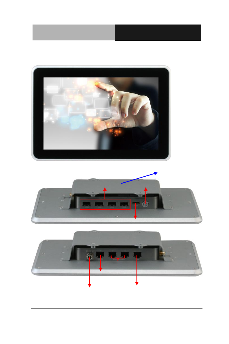
DC input
RS-232
Ethernet Port
RS-232/422/485 x 2
Power button
HDMI
USB x 4
Optional accessory mount kit
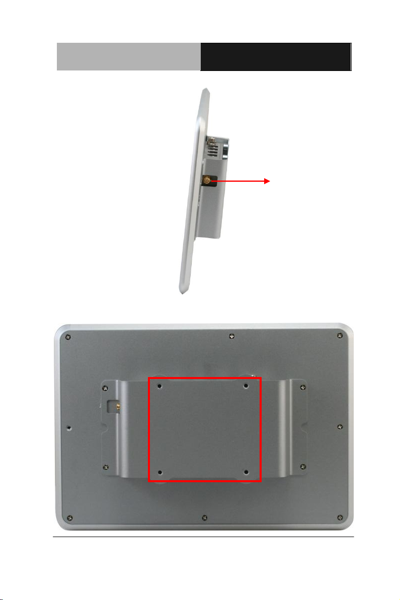
1.4 General Information
Chapter 1 General Information 1-7
Page 21
Multi-Touch Panel PC
ACP- 1103
VESA mount
Antenna
Chapter 1 General Information 1-8
Page 22

Multi-Touch Panel PC
ACP- 1103
Chapter
2
Hardware
Installation
Chapter 2 Hardware Installation 2-1
Page 23
Multi-Touch Panel PC
ACP- 1103
Always completely disconnect the power cord
from your board whenever you are working on
it. Do not make connections while the power is
on, because a sudden rush of power can
damage sensitive electronic components.
Always ground yourself to remove any static
charge before touching the board. Modern
electronic devices are very sensitive to static
electric charges. Use a grounding wrist strap at
all times. Place all electronic components on a
static-dissipative surface or in a static-shielded
bag when they are not in the chassis
2.1 Safety Precautions
Chapter 2 Hardware Installation 2-2
Page 24
Multi-Touch Panel PC
ACP- 1103
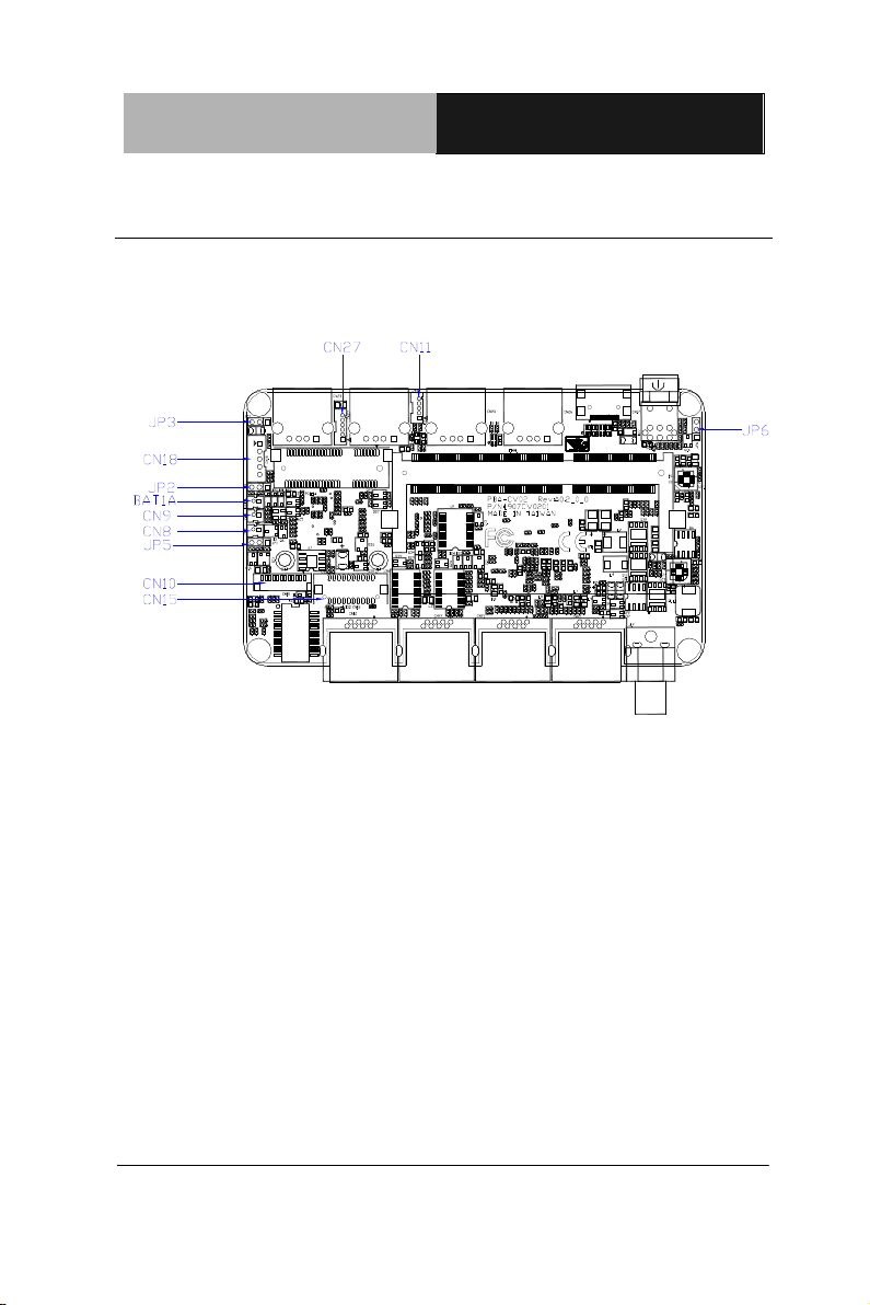
2.2 Connectors and Jumpers of The Main Board
Component Side
Chapter 2 Hardware Installation 2-3
Page 25

Multi-Touch Panel PC
ACP- 1103
Label
Function
JP2
Clear CMOS
JP3
LVDS Voltage Selection
JP5
Inverter Power Selection
JP6
AT/ATX MODE SELECT
2.3 List of Jumpers
The board has a number of jumpers that allow you to configure your
system to suit your application.
The table below shows the function of each of the board's jumpers:
Chapter 2 Hardware Installation 2-4
Page 26

Multi-Touch Panel PC
ACP- 1103
Label
Function
CN7
RJ-45 Ethernet
CN8
BUZZER
CN9
RESET
CN10
LPC Expansion I/F
CN11
1X5 USB Connector
CN15
1X20 LVDS Connector
CN18
LVDS Inverter/ Backlight Connector
CN20
COM1 RS232
CN21
COM2 RS232/422/485
CN22
COM3 RS232/422/485
CN27
1X6 USB Connector
2.4 List of Connectors
The board has a number of connectors that allow you to configure
your system to suit your application. The table below shows the
function of each board's connectors:
Chapter 2 Hardware Installation 2-5
Page 27
Multi-Touch Panel PC
ACP- 1103
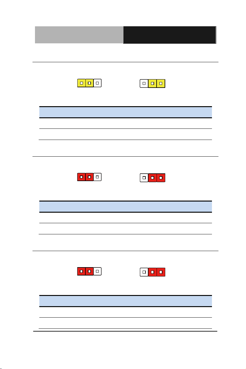
1 2 3
Normal (Default)
1 2 3
Clear CMOS
JP2
Function
1-2
Normal (Default)
2-3
Clear CMOS
1 2 3
+12V
1 2 3
+5V (Default)
JP3
Function
1-2
+12V
2-3
+5V (Default)
1 2 3
+5V
1 2 3
+3.3V (Default)
JP5
Function
1-2
+5V
2-3
+3.3V (Default)
2.5 Clear CMOS Jumper (JP2)
2.6 LVDS Port 1 Backlight Inverter VCC Selection (JP3)
2.7 LVDS Port 1 Operating VDD Selection (JP5)
Chapter 2 Hardware Installation 2-6
Page 28
Multi-Touch Panel PC
ACP- 1103
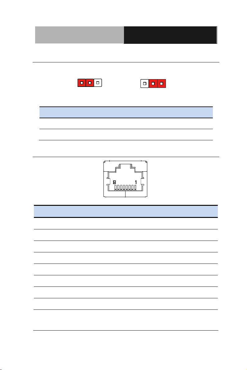
1 2 3
AT Mode
1 2 3
ATX Mode(Default)
JP6
Function
1-2
AT Mode
2-3
ATX Mode(Default)
Pin
Pin Name
Signal Type
Signal Level
1
MDI0+
DIFF
2 MDI0-
DIFF
3
MDI1+
DIFF
4
MDI2+
DIFF
5 MDI2-
DIFF
6 MDI1-
DIFF
7 MDI3+
DIFF
8
MDI3-
DIFF
2.8 AT/ATX Power Supply Mode Selection (JP6)
2.9 Realtek LAN (RJ-45) Port (CN12)
Chapter 2 Hardware Installation 2-7
Page 29
Multi-Touch Panel PC
ACP- 1103
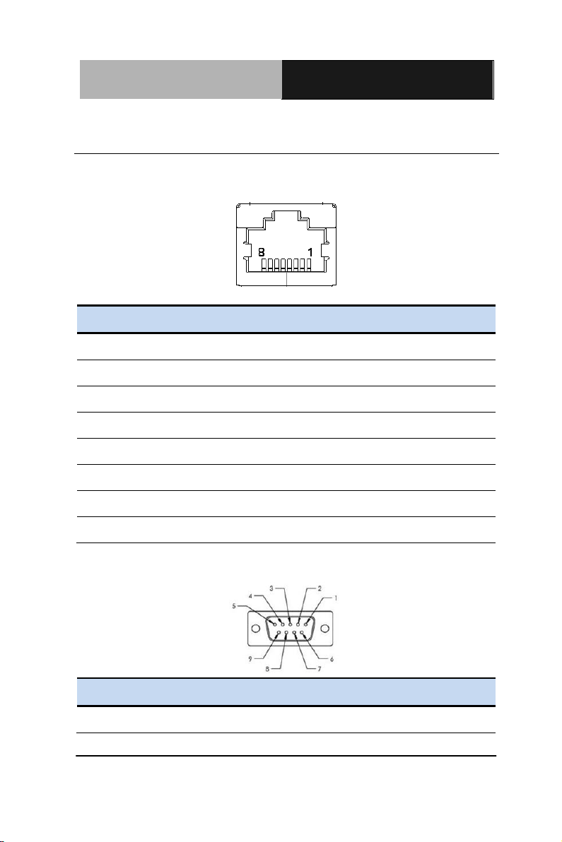
Pin
Pin Name
Signal Type
Signal Level
1
DSR
IN
2 RTS
OUT
3 GND
GND
4 TX
OUT
5 RX
IN
6 DCD
DIFF
7 CTS
IN
8 DTR
OUT
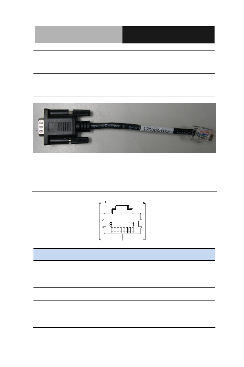
Pin
Signal
Pin
Signal
1
DCD
2
RXD
2.10 COM1,RJ-45 Port (CN20)
RJ-45 port
COM1
Chapter 2 Hardware Installation 2-8
Page 30
Multi-Touch Panel PC
ACP- 1103
3
TXD
4
DTR 5 GND
6
DSR 7 RTS
8
CTS 9 NC
Pin
Pin Name
Signal Type
Signal Level
1
DSR
2
RTS
3
GND
4
TX
RX+
5
RX
DATA+
TX+
Note: 1700090156 External COM Port Converter Cable
2.11 COM2,COM3 RS232/422/485 ,RJ-45 Port
(CN21,CN22)
RJ-45 Port
Chapter 2 Hardware Installation 2-9
Page 31

Multi-Touch Panel PC
ACP- 1103
6
DCD
DATA-
TX-
7
CTS
8
DTR
RX-
Pin
Signal
Pin
Signal
1
DCD
(422TXD-/485DATA-)
2
RXD
(422TXD+/485DATA+)
3
TXD (422RXD+)
4
DTR(422RXD-)
5
GND
6
DSR
7
RTS
8
CTS
9
NC
COM2, COM3
Note: 1700090156 External COM Port Converter Cable
Chapter 2 Hardware Installation 2-10
Page 32

Multi-Touch Panel PC
ACP- 1103
Pin
Pin Name
Signal Type
Signal Level
1
+3.3V
PWR
+3.3V
2
SPK
OUT
Pin
Pin Name
Signal Type
Signal Level
1
RESET
IN
+3.3V 2 GND
GND
8
DTR
OUT
LAD0 1
12
LAD1
LAD2
LAD3
LFRAME#
LRESET#
LDRQ0
LDRQ1
SERIRQ
GND
LCLK
+3.3V
2.12 Buzzer (CN8)
2.13 RESET (CN9)
2.14 LPC Debug Port (CN10)
Chapter 2 Hardware Installation 2-11
Page 33

Multi-Touch Panel PC
ACP- 1103
Pin
Pin Name
Signal Type
Signal Level
1
LAD0
I/O
+3.3V 2 LAD1
I/O
+3.3V 3 LAD2
I/O
+3.3V 4 LAD3
I/O
+3.3V 5 +3.3V
PWR
+3.3V
6
LFRAME#
IN
7 LRESET#
OUT
+3.3V 8 GND
GND
9 LCLK
OUT
10
LDRQ0
IN
11
LDRQ1
IN
12
SERIRQ
I/O
+3.3V
Pin
Pin Name
Signal Type
Signal Level
1
+5V
PWR
+5V 2 USB5_D-
DIFF
3
USB5_D+
DIFF
4
GND
GND
2.15 USB 2.0 Port 5 (CN11)
Chapter 2 Hardware Installation 2-12
Page 34

Multi-Touch Panel PC
ACP- 1103
5
GND
GND
Pin
Pin Name
Signal Type
Signal Level
1
+5V
PWR
+5V 2 USB4_D-
DIFF
3 USB4_D+
DIFF
4 GND
GND
5 GND
GND
6 WIR_DIS
SINGLE
Pin
Pin Name
Signal Type
Signal Level
1
BKL_ENABLE
OUT
3 LCD_PWR
+3.3V/+5V
5
LVDS_A_CLK-
DIFF
7
LVDS_A_CLK+
DIFF
2.16 USB 2.0 Port 4 (CN27)
2.17 18-bits LVDS Output (CN15)
Chapter 2 Hardware Installation 2-13
Page 35

Multi-Touch Panel PC
ACP- 1103
9
LCD_PWR
DIFF
+3.3V/+5V
11
LVDS_DA0+
DIFF
13
LVDS_DA0-
DIFF
15
GND
GND
17
LVDS_DA1+
DIFF
19
LVDS_DA1-
DIFF
2
BKL_CONTROL
OUT
4 LCD_PWR
PWR
+3.3V/+5V
6
LVDS_DA2+
DIFF
8 LVDS_DA2-
DIFF
10
GND
GND
12
LVDS_DA3+
DIFF
14
LVDS_DA3-
DIFF
16
GND
GND
18
DDC_DATA
I/O
+3.3V
20
DDC_CLK
I/O
+3.3V
Pin
Pin Name
Signal Type
Signal Level
1
GND
GND
3 HDMI_TX2-
DIFF
2.18 HDMI Type C (CN17)
Chapter 2 Hardware Installation 2-14
Page 36

Multi-Touch Panel PC
ACP- 1103
5
HDMI_TX1+
DIFF
7 GND
GND
9 HDMI_TX0-
DIFF
11
HDMI_CLK+
DIFF
13
GND
GND
15
HDMI_DDC_CLK
I/O
+5V
17
NC
NC
19
DPD_PWR
PWR
+5V
2
HDMI_TX2+
DIFF
4 GND
GND
6 HDMI_TX1-
DIFF
8 HDMI_TX0+
DIFF
10
GND
GND
12
HDMI_CLK-
DIFF
14
NC
NC
16
HDMI_DDC_DATA
I/O
+5V
18
DPD_HPD
IN
BLK_PWR
2
3
4
5
1
BKL_CONTROL
GND
GND
BKL_ENABLE
2.19 Inverter / Backlight Connector (CN18)
Chapter 2 Hardware Installation 2-15
Page 37

Multi-Touch Panel PC
ACP- 1103
Pin
Pin Name
Signal Type
Signal Level
1
BKL_PWR
PWR
+5V / +12V
2
BKL_CONTROL
OUT
3 GND
GND
4 GND
GND
5 BKL_ENABLE
OUT
+5V
Pin
Pin Name
Signal Type
Signal Level
1
NC
3 NC
5 NC
7 NC
9 GND
GND
11
NC
13
NC
15
GND
GND
17
NC
19
NC
21
GND
GND
23
mSATA_RX+
DIFF
2.20 DDR3 SODIMM Slot (DIMM1)
Standard specification
2.21 Mini Card Slot (mSATA function only)
Chapter 2 Hardware Installation 2-16
Page 38

Multi-Touch Panel PC
ACP- 1103
25
mSATA_RX-
DIFF
27
GND
GND
29
GND
GND
31
mSATA_TX-
DIFF
33
mSATA_TX+
DIFF
35
GND
GND
37
GND
GND
39
+3.3V
PWR
+3.3V
41
+3.3V
PWR
+3.3V
43
NC
45
NC
47
NC
49
NC
51
NC
2
+3.3V
PWR
+3.3V 4 GND
GND
6 +1.5V
PWR
+1.5V 8 NC
9 NC
10
NC
12
NC
14
NC
18
GND
GND
20
NC
Chapter 2 Hardware Installation 2-17
Page 39

Multi-Touch Panel PC
ACP- 1103
22
NC
24
+3.3V
PWR
+3.3V
26
GND
GND
28
+1.5V
PWR
+1.5V
30
SMB_CLK
I/O
+3.3V
32
SMB_DATA
I/O
+3.3V
34
GND
GND
36
NC
38
NC
40
GND
GND
42
NC
44
NC
46
NC
48
+1.5V
PWR
+1.5V
50
GND
GND
52
+3.3V
PWR
+3.3V
Chapter 2 Hardware Installation 2-18
Page 40

Multi-Touch Panel PC
ACP- 1103
26 5.95
18 3.55
30
136
79 .6
2.22 Mechanical Drawing of the ACP-1103
Chapter 2 Hardware Installation 2-19
Page 41

Multi-Touch Panel PC
ACP- 1103
Wall mount bracket
Sponge
1
3-screw
Sponge
Wall mount bracket
2.23 How to Embed the ACP-1103
Step 1: Get the wallmount bracket and sponge ready.
Step 2: Unfasten the six screws (three screws on each side respectively)
and put the wallmount bracket to ACP-1103. Then, fasten the original six
screws back to the ACP-1103.
Step 3: Cover the sponge to the wallmount bracket
Chapter 2 Hardware Installation 2-20
Page 42

Multi-Touch Panel PC
ACP- 1103
wall
4-mounting clip
1
2
Opening
M4x60 screw
Step 4: Insert the ACP-1103 to the place (opening) where you are going to
embed the ACP-1103
Step 5: Insert the mounting clips to the four fillisters on wallmount bracket
and fasten the four M4x60 screws to lock the bracket
Chapter 2 Hardware Installation 2-21
Page 43

Multi-Touch Panel PC
ACP- 1103
Chapter
3
AMI
BIOS Setup
Chapter 3 AMI BIOS Setup 3-1
Page 44

Multi-Touch Panel PC
ACP- 1103
3.1 System Test and Iinitialization
These routines test and initialize board hardware. If the routines
encounter an error during the tests, you will either hear a few short
beeps or see an error message on the screen. There are two kinds
of errors: fatal and non-fatal. The system can usually continue the
boot up sequence with non-fatal errors.
System configuration verification
These routines check the current system configuration stored in the
CMOS memory and BIOS NVRAM. If system configuration is not
found or system configuration data error is detected, system will
load optimized default and re-boot with this default system
configuration automatically.
There are four situations in which you will need to setup system
configuration:
1. You are starting your system for the first time
2. You have changed the hardware attached to your system
3. The system configuration is reset by Clear-CMOS jumper
4. The CMOS memory has lost power and the configuration
information has been erased.
The ACP-1103 CMOS memory has an integral lithium battery
backup for data retention. However, you will need to replace the
complete unit when it finally runs down.
Chapter 3 AMI BIOS Setup 3-2
Page 45

Multi-Touch Panel PC
ACP- 1103
3.2 AMI BIOS Setup
AMI BIOS ROM has a built-in Setup program that allows users to
modify the basic system configuration. This type of information is
stored in battery-backed CMOS RAM and BIOS NVRAM so that it
retains the Setup information when the power is turned off.
Entering Setup
Power on the computer and press <Del>or <F2> immediately. This
will allow you to enter Setup.
Main
Set the date, use tab to switch between date elements.
Advanced
Enable disable boot option for legacy network devices.
Chipset
Host bridge parameters.
Boot
Enables/disable quiet boot option.
Security
Set setup administrator password.
Save & Exit
Exit system setup after saving the changes.
Chapter 3 AMI BIOS Setup 3-3
Page 46

Multi-Touch Panel PC
ACP- 1103
System Date
Day MM:DD:YYYY
Change the month, year and century. The ‘Day’ is changed automatically.
System Time
HH : MM : SS
Change the clock of the system.
Setup Menu
Setup submenu: Main
Options summary: (default setting)
Chapter 3 AMI BIOS Setup 3-4
Page 47

Multi-Touch Panel PC
ACP- 1103
ACPI Settings
System ACPI Parameters
CPU Configuration
CPU Configuration Parameters
IDE Configuration
IDE Device Options Settings
USB Configuration
USB Configuration Parameters
F81801 Super IO Configuration
System Super IO Parameters
Setup submenu: Advanced
Options summary: (default setting)
Chapter 3 AMI BIOS Setup 3-5
Page 48

Multi-Touch Panel PC
ACP- 1103
F81216 Second Super IO Configuration
System Second Super IO Parameters
Digital IO Port Configuration
DIO configuration
H/W Monitor
Monitor hardware status
Chapter 3 AMI BIOS Setup 3-6
Page 49

Multi-Touch Panel PC
ACP- 1103
Enable Hibernation
Enabled
Disabled
Enabled or disabled hibernate (OS/S4 Sleep State).
ACPI Sleep State
Suspend Disabled
S1 only(CPU Stop Clock)
S3 only(Suspend to RAM)
AUTO
Select the ACPI state used for System Suspend
Wake on Ring
Enabled
ACPI Settings
Options summary: (default setting)
Chapter 3 AMI BIOS Setup 3-7
Page 50

Multi-Touch Panel PC
ACP- 1103
Disabled
Enabled or disabled wake on ring function.
RTC Wake Settings
Enable system to wake from S5 using RTC alarm.
Chapter 3 AMI BIOS Setup 3-8
Page 51

Multi-Touch Panel PC
ACP- 1103
Wake system with Fixed
Time
Disabled
Enabled
Enable or disable System wake on alarm event. Wake up time is setting by following
settings.
Wake up day
0-31
Select 0 for daily system wake up 1-31 for which day of the month that you would
like the system to wake up
Wake up hour
0-23
RTC Wake Settings
Options summary: (default setting)
Chapter 3 AMI BIOS Setup 3-9
Page 52

Multi-Touch Panel PC
ACP- 1103
Wake up minute
0-59
Wake up second
0-59
Wake system with
Dynamic Time
Disabled
Enabled
Enable or disable System wake on alarm event. Wake up time is current time +
Increase minutes.
Wake up minute increase
1-5
Chapter 3 AMI BIOS Setup 3-10
Page 53

Multi-Touch Panel PC
ACP- 1103
Hyper-Threading
Disabled
Enabled
En/Disable CPU Hyper-Threading function
Execute Disable Bit
Disabled
Enabled
En/Disable XD bit for supporting OS
Limit CPUID Maximum
Disabled
Enabled
Disabled for Windows XP
CPU Smart Thermal Control
Disabled
CPU Configuration
Options summary: (default setting)
Chapter 3 AMI BIOS Setup 3-11
Page 54

Multi-Touch Panel PC
ACP- 1103
55 60 65 70
CPU will reduce frequency automatically when CPU temperature higher than the
setting value.
Chapter 3 AMI BIOS Setup 3-12
Page 55

Multi-Touch Panel PC
ACP- 1103
SATA Controller(s)
Disabled
Enabled
En/Disable SATA controller
Configure SATA as
IDE AHCI
Configure SATA controller operating as IDE/AHCI mode.
IDE Configuration
Options summary: (default setting)
Chapter 3 AMI BIOS Setup 3-13
Page 56

Multi-Touch Panel PC
ACP- 1103
Legacy USB Support
Enabled
Disabled
Auto
Enables BIOS Support for Legacy USB Support. When enabled, USB can be
functional in legacy environment like DOS. AUTO option disables legacy support if
no USB devices are connected. DISABLE option will keep USB devices available
only for EFI application
Device Name
(Emulation Type)
Auto
Floppy
USB Configuration
Options summary: (default setting)
Chapter 3 AMI BIOS Setup 3-14
Page 57

Multi-Touch Panel PC
ACP- 1103
Forced FDD
Hard Disk
CD-ROM
If Auto. USB devices less than 530MB will be emulated as Floppy and remaining as
Floppy and remaining as hard drive. Forced FDD option can be used to force a
HDD formatted drive to boot as FDD(Ex. ZIP drive)
Chapter 3 AMI BIOS Setup 3-15
Page 58

Multi-Touch Panel PC
ACP- 1103
Serial Port 1/2 Configuration
Set Parameters of Serial Port 1/2
F81801 Super IO Configuration
Options summary: (default setting)
Chapter 3 AMI BIOS Setup 3-16
Page 59

Multi-Touch Panel PC
ACP- 1103
Serial Port
Disabled
Enabled
En/Disable specified serial port.
Change Settings
Auto
IO=3F8h; IRQ=4;
IO=3F8h; IRQ=3,4,5,7,10,11,12;
IO=2F8h; IRQ=3,4,5,7,10,11,12;
IO=3E8h; IRQ=3,4,5,7,10,11,12;
IO=2E8h; IRQ=3,4,5,7,10,11,12;
Serial Port 1 Configuration
Options summary: (default setting)
Chapter 3 AMI BIOS Setup 3-17
Page 60

Multi-Touch Panel PC
ACP- 1103
Select a resource setting for Super IO device.
Chapter 3 AMI BIOS Setup 3-18
Page 61

Multi-Touch Panel PC
ACP- 1103
Serial Port
Disabled
Enabled
En/Disable specified serial port.
Change Settings
Auto
IO=2F8h; IRQ=3;
IO=3F8h; IRQ=3,4,5,7,10,11,12;
IO=2F8h; IRQ=3,4,5,7,10,11,12;
IO=3E8h; IRQ=3,4,5,7,10,11,12;
IO=2E8h; IRQ=3,4,5,7,10,11,12;
Serial Port 2 Configuration
Options summary: (default setting)
Chapter 3 AMI BIOS Setup 3-19
Page 62

Multi-Touch Panel PC
ACP- 1103
Select a resource setting for Super IO device.
Device Type
RS232
RS422
RS485
Configure COM2 operated as RS232, RS422 or RS485.
Chapter 3 AMI BIOS Setup 3-20
Page 63

Multi-Touch Panel PC
ACP- 1103
Serial Port 3 Configuration
Set Parameters of Serial Port 3
F81216 Second Super IO Configuration
Options summary: (default setting)
Chapter 3 AMI BIOS Setup 3-21
Page 64

Multi-Touch Panel PC
ACP- 1103
Serial Port
Disabled
Enabled
En/Disable specified serial port.
Change Settings
Auto
IO=2C0h; IRQ=5;
IO=2C0h; IRQ=3,4,5,9,10,11;
IO=2C8h; IRQ=3,4,5,9,10,11;
IO=2B0h; IRQ=3,4,5,9,10,11;
IO=2B8h; IRQ=3,4,5,9,10,11;
Select a resource setting for Super IO device.
Serial Port 3 Configuration
Options summary: (default setting)
Chapter 3 AMI BIOS Setup 3-22
Page 65

Multi-Touch Panel PC
ACP- 1103
Device Type
RS232
RS422
RS485
Configure COM2 operated as RS232, RS422 or RS485.
Chapter 3 AMI BIOS Setup 3-23
Page 66

Multi-Touch Panel PC
ACP- 1103
H/W Monitor
Chapter 3 AMI BIOS Setup 3-24
Page 67

Multi-Touch Panel PC
ACP- 1103
Host Bridge
Host Bridge Parameters
South Bridge
South Bridge Parameters
Setup submenu: Chipset
Options summary: (default setting)
Chapter 3 AMI BIOS Setup 3-25
Page 68

Multi-Touch Panel PC
ACP- 1103
Fixed Graphics Memory
Size
128MB
256MB
Configure Fixed Graphics Memory Size
IGFX – Boot Type
LVDS
HDMI
Select the Video Device which will be activated during POST.
LVDS Backlight Level
80%
0~100%
Select Backlight brightness of LVDS
Host Bridge
Options summary: (default setting)
Chapter 3 AMI BIOS Setup 3-26
Page 69

Multi-Touch Panel PC
ACP- 1103
Onboard Devices
Onboard devices parameters configurations
High Precision Timer
Enabled
Disabled
Enable or Disable the High Precision Event Timer
Power Mode
ATX Type
AT Type
Select the power type used on the system
SLP_S4 Assertion Width
1-2 Seconds
2-3 Seconds
South Bridge
Options summary: (default setting)
Chapter 3 AMI BIOS Setup 3-27
Page 70

Multi-Touch Panel PC
ACP- 1103
3-4 Seconds
4-5 Seconds
Select a minimum assertion width of the SLP_S4# signal
Restore AC Power Loss
Power On
Power Off
Last State
Select AC power state when power is re-applied after a power failure.
Chapter 3 AMI BIOS Setup 3-28
Page 71

Multi-Touch Panel PC
ACP- 1103
Azalia Controller
Disabled
HD Audio
Select a OnBoard Azalia Configuration
LAN Controller
Disabled
Enabled
Enable or disable Realtek R8111E PCIE LAN Device
SMBus Controller
Disabled
Enabled
Enable or Disable OnChip SMBus Controller
Onboard Devices
Options summary: (default setting)
Chapter 3 AMI BIOS Setup 3-29
Page 72

Multi-Touch Panel PC
ACP- 1103
Quiet Boot
Disabled
Enabled
En/Disable showing boot logo.
Launch LAN PXE OpROM
Disabled
Enabled
En/Disable PXE boot for RTL8111E LAN
Boot Option #X/
XXXX Drive BBS Priorities
The order of boot priorities.
Setup submenu: Boot
Options summary: (default setting)
Chapter 3 AMI BIOS Setup 3-30
Page 73

Multi-Touch Panel PC
ACP- 1103
Boot Option #x
Disabled
Device name
Sets the system boot order
BBS Priorities
Options summary: (default setting)
Chapter 3 AMI BIOS Setup 3-31
Page 74

Multi-Touch Panel PC
ACP- 1103
Administrator Password/
User Password
Not set
You can install a Supervisor password, and if you install a supervisor password, you
can then install a user password. A user password does not provide access to many
of the features in the Setup utility.
Install the Password:
Press Enter on this item, a dialog box appears which lets you enter a password. You
can enter no more than six letters or numbers. Press Enter after you have typed in
the password. A second dialog box asks you to retype the password for
confirmation. Press Enter after you have retyped it correctly. The password is
Setup submenu: Security
Options summary: (default setting)
Chapter 3 AMI BIOS Setup 3-32
Page 75

Multi-Touch Panel PC
ACP- 1103
required at boot time, or when the user enters the Setup utility.
Removing the Password:
Highlight this item and type in the current password. At the next dialog box press
Enter to disable password protection.
Chapter 3 AMI BIOS Setup 3-33
Page 76

Multi-Touch Panel PC
ACP- 1103
Set User Password/
Set Master Password
Not set
You can install a Master and User password. Before booting to OS, HDD will be set
to frozen state. On S3 resume HDD will be unlocked using the HDD Password we
entered while system booting.
Install the Password:
Press Enter on this item, a dialog box appears which lets you enter a password. You
can enter no more than six letters or numbers. Press Enter after you have typed in
the password. A second dialog box asks you to retype the password for
confirmation. Press Enter after you have retyped it correctly. The password is
HDD Security
Options summary: (default setting)
Chapter 3 AMI BIOS Setup 3-34
Page 77

Multi-Touch Panel PC
ACP- 1103
required at boot time, or when the user enters the Setup utility.
Removing the Password:
Highlight this item and type in the current password. At the next dialog box press
Enter to disable password protection.
Chapter 3 AMI BIOS Setup 3-35
Page 78

Multi-Touch Panel PC
ACP- 1103
Save Changes and Reset
Reset the system after saving the changes
Discard Changes and Reset
Reset system setup without saving any changes
Restore Defaults
Restore/Load Default values for all the setup options.
Save as User Defaults
Save the changes done so far as User Defaults
Restore User Defaults
Setup submenu: Exit
Options summary: (default setting)
Chapter 3 AMI BIOS Setup 3-36
Page 79

Multi-Touch Panel PC
ACP- 1103
Restore the User Defaults to all the setup options
Chapter 3 AMI BIOS Setup 3-37
Page 80

Multi-Touch Panel PC
ACP- 1103
Chapter
4
Driver
Installation
Chapter 4 Driver Installation 4-1
Page 81

Multi-Touch Panel PC
ACP - 1103
The ACP-1103 comes with an AutoRun CD-ROM that contains all
drivers and utilities that can help you to install the driver
automatically.
Insert the driver CD, the driver CD-title will auto start and show the
installation guide. If not, please follow the sequence below to install
the drivers.
Follow the sequence below to install the drivers:
Step 1 – Install Chipset Driver
Step 2 – Install VGA Driver
Step 3 – Install LAN Driver
Step 4 – Install AHCI Driver
Step 5 – Install Serial Port Driver (Optional)
Step 6 – Install Wireless Driver (Optional)
Please read instructions below for further detailed installations.
Chapter 4 Driver Installation 4-2
Page 82

Multi-Touch Panel PC
ACP- 1103
4.1 Installation:
Insert the ACP-1103 CD-ROM into the CD-ROM drive. And install
the drivers from Step 1 to Step 6 in order.
Step 1 – Install Chipset Driver
1. Click on the STEP1-Chipset folder and select the OS
folder your system is
2. Double click on the infinst_autol_1034.exe file located in
each OS folder
3. Follow the instructions that the window shows
4. The system will help you install the driver automatically
Step 2 – Install VGA Driver
For Windows® 7
1. Click on the STEP2-VGA folder and select the folder of
WIN7_32
2. Double click on the Setup.exe file
3. Follow the instructions that the window shows
4. The system will help you install the driver automatically
For Windows® XP
1. Click on the dotnetfx35.exe and select the folder of
WINXP_32
2. Double click on the WindowsDriverSETUP.exe file
located in WINXP_32 folder
3. Follow the instructions that the window shows
Chapter 4 Driver Installation 4-3
Page 83

Multi-Touch Panel PC
ACP - 1103
4. The system will help you install the driver automatically
Step 3 –Install LAN Driver
1. Click on the STEP3-LAN folder and select the OS
folder your system is
2. Double click on the setup.exe file located in each OS
folder
3. Follow the instructions that the window shows
4. The system will help you install the driver automatically
Step 4 – Install AHCI Driver
Please refer to the Appendix D AHCI Setting
Step 5 –Install Serial Port Driver (Optional)
Chapter 4 Driver Installation 4-4
Page 84

Multi-Touch Panel PC
ACP- 1103
Chapter 4 Driver Installation 4-5
Page 85

Multi-Touch Panel PC
ACP - 1103
Chapter 4 Driver Installation 4-6
Page 86

Multi-Touch Panel PC
ACP- 1103
Step 6 – Install Wireless Driver (Optional)
1. Click on the STEP6-Wireless (Optional) folder and select
the OS folder your system is
2. Double click on the VN9271_Windows_V1.3.0.0_x86.exe
file located in each OS folder
3. Follow the instructions that the window shows
4. The system will help you install the driver automatically
Chapter 4 Driver Installation 4-7
Page 87

Multi-Touch Panel PC
ACP- 1103
Appendix
A
Programming the
Watchdog Timer
Appendix A Programming the Watchdog Timer A-1
Page 88

Multi-Touch Panel PC
ACP- 1103
Table 1 : Watch dog relative IO address
Default Value
Note
I/O Base
Address
0xA00
I/O Base address for Watchdog operation.
This address is assigned by SIO LDN7, register 0x60-0x61.
Table 2 : Watchdog relative register table
Register
Offset
BitNum
Value
Note
Watchdog
WDTRST# Enable
0x00 7 1
Enable/Disable
time out output via WDTRST#
0: Disable
1: Enable
Pulse Width
0x05
0:1
01
Width of Pulse signal
00: 1ms (do not use)
01: 25ms
10: 125ms
11: 5s
Pulse width is must longer then
16ms.
Signal Polarity
0x05 2 0
0: low active
1: high active
Must set this bit to 0
Counting Unit
0x05 3 0
Select time unit.
0: second
1: minute
Output Signal
Type
0x05 4 1
0: Level
1: Pulse
Must set this bit to 1
Watchdog Timer
Enable
0x05 5 1
0: Disable
1: Enable
Timeout Status
0x05 6 1
1: timeout occurred. Write a 1
to clear timeout status
Timer Counter
0x06
Time of watchdog timer
(0~255)
A.1 Watchdog Timer Registers
Appendix A Programming the Watchdog Timer A-2
Page 89

Multi-Touch Panel PC
ACP- 1103
A.2 Watchdog Sample Program
**************************************************************************
****
// WDT I/O operation relative definition (Please reference to Table 1)
#define WDTAddr 0xA00 // WDT I/O base address
Void WDTWriteByte(byte Register, byte Value);
byte WDTReadByte(byte Register);
Void WDTSetReg(byte Register, byte Bit, byte Val);
// Watch Dog relative definition (Please reference to Table 2)
#define DevReg 0x00 // Device configuration register
#define WDTRstBit 0x80 // Watchdog WDTRST# (Bit7)
#define WDTRstVal 0x80 // Enabled WDTRST#
#define TimerReg 0x05 // Timer register
#define PSWidthBit 0x00 // WDTRST# Pulse width (Bit0:1)
#define PSWidthVal 0x01 // 25ms for WDTRST# pulse
#define PolarityBit 0x02 // WDTRST# Signal polarity (Bit2)
#define PolarityVal 0x00 // Low active for WDTRST#
#define UnitBit 0x03 // Unit for timer (Bit3)
#define ModeBit 0x04 // WDTRST# mode (Bit4)
#define ModeVal 0x01 // 0:level 1: pulse
#define EnableBit 0x05 // WDT timer enable (Bit5)
#define EnableVal 0x01 // 1: enable
#define StatusBit 0x06 // WDT timer status (Bit6)
#define CounterReg 0x06 // Timer counter register
**************************************************************************
**************************************************************************
VOID Main(){
// Procedure : AaeonWDTConfig
// (byte)Timer : Counter of WDT timer.(0x00~0xFF)
// (boolean)Unit : Select time unit(0: second, 1: minute).
AaeonWDTConfig(Counter, Unit);
// Procedure : AaeonWDTEnable
Appendix A Programming the Watchdog Timer A-3
Page 90

Multi-Touch Panel PC
ACP- 1103
// This procudure will enable the WDT counting.
AaeonWDTEnable();
}
**************************************************************************
**************************************************************************
// Procedure : AaeonWDTEnable
VOID AaeonWDTEnable (){
WDTEnableDisable(1);
}
// Procedure : AaeonWDTConfig
VOID AaeonWDTConfig (byte Counter, BOOLEAN Unit){
// Disable WDT counting
WDTEnableDisable(0);
// Clear Watchdog Timeout Status
WDTClearTimeoutStatus();
// WDT relative parameter setting
WDTParameterSetting(Timer, Unit);
}
VOID WDTEnableDisable(byte Value){
If (Value == 1)
WDTSetBit(TimerReg, EnableBit, 1);
else
WDTSetBit(TimerReg, EnableBit, 0);
}
VOID WDTParameterSetting(byte Counter, BOOLEAN Unit){
// Watchdog Timer counter setting
WDTWriteByte(CounterReg, Counter);
// WDT counting unit setting
WDTSetBit(TimerReg, UnitBit, Unit);
// WDT output mode set to pulse
WDTSetBit(TimerReg, ModeBit, ModeVal);
// WDT output mode set to active low
WDTSetBit(TimerReg, PolarityBit, PolarityVal);
Appendix A Programming the Watchdog Timer A-4
Page 91

Multi-Touch Panel PC
ACP- 1103
// WDT output pulse width is 25ms
WDTSetBit(TimerReg, PSWidthBit, PSWidthVal);
// Watchdog WDTRST# Enable
WDTSetBit(DevReg, WDTRstBit, WDTRstVal);
}
VOID WDTClearTimeoutStatus(){
WDTSetBit(TimerReg, StatusBit, 1);
}
**************************************************************************
**************************************************************************
VOID WDTWriteByte(byte Register, byte Value){
IOWriteByte(WDTAddr+Register, Value);
}
byte WDTReadByte(byte Register){
return IOReadByte(WDTAddr+Register);
}
VOID WDTSetBit(byte Register, byte Bit, byte Val){
byte TmpValue;
TmpValue = WDTReadByte(Register);
TmpValue &= ~(1 << Bit);
TmpValue |= Val << Bit;
WDTWriteByte(Register, TmpValue);
}
**************************************************************************
Appendix A Programming the Watchdog Timer A-5
Page 92

Multi-Touch Panel PC
ACP- 1103
Appendix
B
I/O Information
Appendix B I/O Information B-1
Page 93

Multi-Touch Panel PC
ACP- 1103
B.1 I/O Address Map
Appendix B I/O Information B-2
Page 94

Multi-Touch Panel PC
ACP- 1103
Appendix B I/O Information B-3
Page 95

Multi-Touch Panel PC
ACP- 1103
B.2 Memory Address Map
Appendix B I/O Information B-4
Page 96

Multi-Touch Panel PC
ACP- 1103
B.3 IRQ Mapping Chart
Appendix B I/O Information B-5
Page 97

Multi-Touch Panel PC
ACP- 1103
Appendix B I/O Information B-6
Page 98

Multi-Touch Panel PC
ACP- 1103
B.4 DMA Channel Assignments
Appendix B I/O Information B-7
Page 99

Multi-Touch Panel PC
ACP- 1103
Appendix
C
Miscellanea
Appendix C Miscellanea C-1
Page 100

Multi-Touch Panel PC
ACP- 1103
C.1 General Cleaning Tips
You may need the following precautions before you begin to clean
the computer. When you clean any single part or component for the
computer, please read and understand the details below fully.
1. Never spray or squirt the liquids directly onto any computer
component. If you need to clean the device, please rub it
with a piece of dry cloth.
2. Be cautious of the tiny removable components when you
use a vacuum cleaner to absorb the dirt on the floor.
3. Turn the system off before you start to clean up the
component or computer.
4. Never drop the components inside the computer or get
circuit board damp or wet.
5. Be cautious of all kinds of cleaning solvents or chemicals
when you use it for the sake of cleaning. Some individuals
may be allergic to the ingredients.
6. Try not to put any food, drinks or cigarettes around the
computer.
Appendix C Miscellanea C-2
 Loading...