

Page 1

LCD Display ACD-515D
ACD-515D
15.6” WXGA Infotainment Touch Display
On Screen Display Control
IP-65 Front Bezel
Projected Capacitive Multi-Touch Screen
ACD-515D Manual 1
October 2011
st
Ed
Page 2

LCD Display ACD-515D
Copyright Notice
This document is copyrighted, 2011. All rights are reserved. The
original manufacturer reserves the right to make improvements to
the products described in this manual at any time without notice.
No part of this manual may be reproduced, copied, translated, or
transmitted in any form or by any means without the prior written
permission of the original manufacturer. Information provided in this
manual is intended to be accurate and reliable. However, the
original manufacturer assumes no responsibility for its use, nor for
any infringements upon the rights of third parties, which may result
from its use.
The material in this document is for product information only and is
subject to change without notice. While reasonable efforts have
been made in the preparation of this document to assure its
accuracy, AAEON, assumes no liabilities resulting from errors or
omissions in this document, or from the use of the information
contained herein.
AAEON reserves the right to make changes in the product design
without notice to its users.
i
Page 3

LCD Display ACD-515D
Acknowledgments
Intel
IBM, PC/AT, PS/2 are trademarks of International Business
®
is registered trademarks of Intel® Corporation.
Machines Corporation.
Microsoft
®
Windows is a registered trademark of Microsoft®
Corporation.
RTL is a trademark of Realtek Semi-Conductor Co., Ltd.
C&T is a trademark of Chips and Technologies, Inc.
UMC is a trademark of United Microelectronics Corporation.
ITE is a trademark of Integrated Technology Express, Inc.
SiS is a trademark of Silicon Integrated Systems Corp.
VIA is a trademark of VIA Technology, Inc.
All other product names or trademarks are properties of their
respective owners.
ii
Page 4

LCD Display ACD-515D
Packing List
The LCD monitor comes with the following standard parts shown as
below. Check and make sure they are included and in good condition.
If anything is missing or damaged, contact the dealer immediately.
1 ACD-515D
1 Utility CD-ROM
Contains User’s Manual (in PDF format), Drivers and
Utilities
1 VGA Cable
1 USB Cable
1 AC/DC 12V Power Adapter with Lock
If any of these items are missing or damaged, you should cont act y our
distributor or sales representative immediately.
iii
Page 5

LCD Display ACD-515D
Safety & Warranty
1. Read these safety instructions carefully.
2. Keep this user's manual for later reference.
3. Disconnect this equipment from any AC outlet before cleaning. Do
not use liquid or spray detergents for cleaning. Use a damp cl oth.
4. For pluggable equipment, the power outlet must be installed near
the equipment and must be easily accessible.
5. Keep this equipment away from humidity.
6. Put this equipment on a reliable surface during installation.
Dropping it or letting it fall could cause damage.
7. The openings on the enclosure are for air convection. Protect the
equipment from overheating. DO NOT COVER THE OPENINGS.
8. Make sure the voltage of the power source is correct before
connecting the equipment to the power outlet.
9. Position the power cord so that people cannot step on it. Do not
place anything over the power cord.
10. All cautions and warnings on the equipment should be noted.
11. If the equipment is not used for a long time, disconnect it from the
power source to avoid damage by transient over-voltage.
12. Never pour any liquid into an opening. This could cause fire or
electrical shock.
13. Never open the equipment. For safety reasons, only qualified
service personnel should open the equipment.
iv
Page 6

LCD Display ACD-515D
14. If any of the following situations arises, get the equipment
checked by service personnel:
a. The power cord or plug is damaged.
b. Liquid has penetrated into the equipment.
c. The equipment has been exposed to moisture.
d. The equipment does not work well, or you cannot get it to
work according to the users manual.
e. The equipment has been dropped and damaged.
f. The equipment has obvious signs of breakage.
15. DO NOT LEAVE THIS EQUIPMENT IN AN UNCONTROLLED
ENVIRONMENT WHERE THE STORAGE TEMPERATURE IS
BELOW -20° C (-4°F) OR ABOVE 60° C (140° F). IT MAY
DAMAGE THE EQUIPMENT
.
FCC
Cautio
This device complies with Part 15 FCC Rules.
Operation is subject to the following two
conditions: (1) this device may not cause
harmful interference, and (2) this device
must accept any interference received
including interference that may cause
undesired operation.
n:
It may cause the danger of explosion if battery is incorrectly
replaced. Replace only with same or equivalent type
recommended by the manufacturer.
v
Page 7
LCD Display ACD-515D
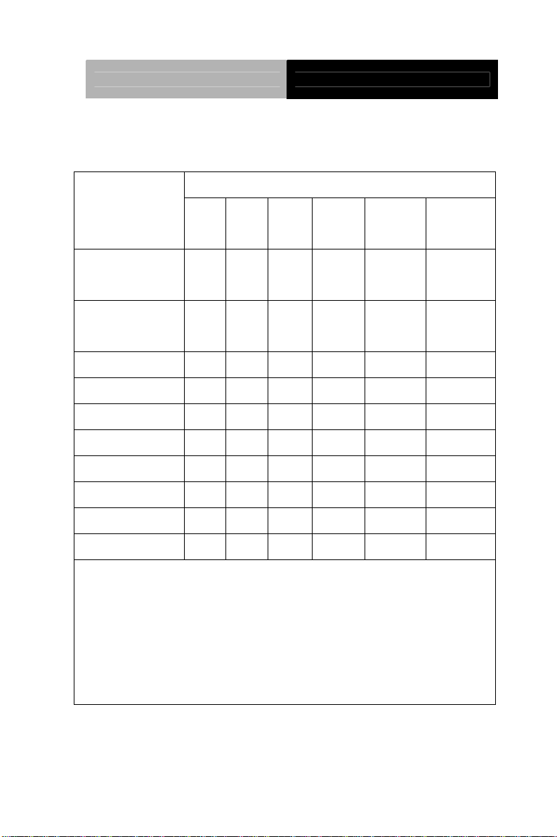
Below Table for China RoHS Requirements
产品中有毒有害物质或元素名称及含量
AAEON Display
有毒有害物质或元素
部件名称
印刷电路板
及其电子组件
外部信号
连接器及线材
外壳 × ○ ○ ○ ○ ○
液晶模块 × ○ ○ ○ ○ ○
触控模块 × ○ ○ ○ ○ ○
电源 × ○ ○ ○ ○ ○
O:表示该有毒有害物质在该部件所有均质材料中的含量均在
SJ/T 11363-2006 标准规定的限量要求以下。
X:表示该有毒有害物质至少在该部件的某一均质材料中的含量超出
SJ/T 11363-2006 标准规定的限量要求。
备注:
一、此产品所标示之环保使用期限,系指在一般正常使用状况下。
二、上述部件物质触控模块为选购品。
铅
(Pb)汞 (Hg)镉 (Cd)
× ○ ○ ○ ○ ○
× ○ ○ ○ ○ ○
六价铬
(Cr(VI))
多溴联苯
(PBB)
多溴二苯醚
(PBDE)
vi
Page 8

LCD Display ACD-515D
Contents
Chapter 1 General Information
1.1 Introduction................................................................ 1-2
1.2 Features....................................................................1-3
1.3 General Specification................................................1-4
1.4 Dimension .................................................................1-6
Chapter 2 Hardware Installation
2.1 Before Unpacking...................................................... 2-2
2.2 Connecting Power..................................................... 2-3
2.3 Connecting to the Computer.....................................2-4
2.4 VGA Port Connector..................................................2-5
2.5 DVI Port Connector...................................................2-6
2.6 Serial Port Connector For Touch Screen.................. 2-7
2.7 Mini USB Connector For Touch Screen....................2-8
2.8 VESA Wall Mounting................................................. 2-9
Chapter 3 On Screen Display Control
3.1 On Screen Display (OSD) Board Description. .......... 3-2
3.2 OSD Main Menu: Push The MENU Keys..................3-3
3.3 Select Input Source................................................... 3-4
3.4 Contrast/ Brightness- Submenu................................ 3-5
3.5 Geometry Menu.........................................................3-6
3.6 Color Temperature- Submenu OSD Main Menu: Push
vii
Page 9

LCD Display ACD-515D
The MENU Keys.............................................................. 3-7
3.7 RGB Color- Submenu. .............................................. 3-8
3.8 Language- Submenu................................................. 3-9
3.9 Auto Config- Submenu..............................................3-10
3.10 Mode Resolution- Submenu Chapter...................... 3-11
3.11 Exit Menu- Submenu............................................... 3-12
Chapter 4 Touch Screen Driver Installation
4.1 Introduction................................................................ 4-2
4.2 Installing Driver for Windows
® XP/ Windows® 7 / Linux
.........................................................................................4-2
viii
Page 10

LCD Display ACD-515D
Chapter
1
General
Information
Chapter 1 General Information 1-1
Page 11

LCD Display ACD-515D
1.1 Introduction
Thank you for purchasing of the Industry Display Panel TFT LCD
monitor - a marvelous contribution of cutting-edge technology.
The LCD monitor has been designed with serious thoughts to
present the best performance for most applications. Symbol of
elegance, its compact and slim profile are well suited in working
locations where space is at a premium.
The TFT LCD monitor displays sharper, more brilliant, crisper and
flicker-free images. Complying with the power management
regulations of VESA DPMS, the LCD monitor is extremely energy
efficient and a power saver. Plus, the LCD monitor has extremely
low radiation emissions and near zero electromagnetic fields which
are supreme benefits.
Fully compatible with PC system, the LCD monitor provides full
interface for all sorts of related standards. Supported by “Plug &
Play” complying with DDC1/DDC2B, installing the LCD monitor is
absolutely trouble free.
The On Screen Display menu provides user a convenient interface
to make right adjustment for optimum display performance.
Chapter 1 General Information 1-2
Page 12

LCD Display ACD-515D
1.2 Features
15.6” WXGA (1366 x 768) TFT LCD Display
Easy-To-Clean: Multi-Touch Window Design (Two-Point)
Easy To Maintain: USB Ports On Two Sides
IPx1 Water-proof Design For Whole System
Anti-Scratch Surface (7H Hardness)
Chapter 1 General Information 1-3
Page 13

LCD Display ACD-515D
1.3 General Specification
Type
Size
Construction
Mounting
Input signal
Control
Power Supply
Dimension
Gross Weight
Power Input
Brightness
MTBF
Contrast Ratio
Viewing Angle
Resolution
Display Modes
Color TFT
15.6" TFT LCD
Plastic front bezel and steel back chassis
VESA/ Wallmount
VGA, DVI
OSD (On Screen Display) on the panel
External power adapter
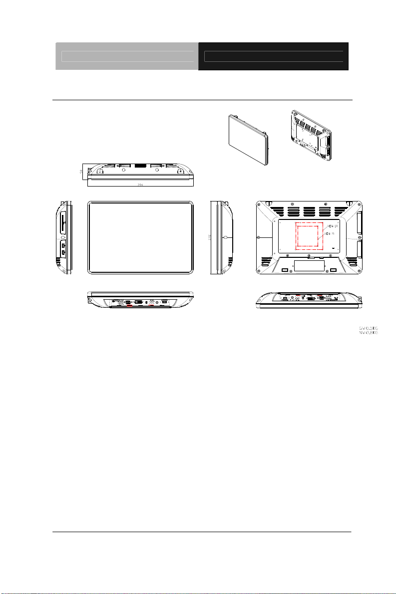
15.51” (W) x 10.71”(H) x 2.36”(D) (394mm x
272mm x 59mm
14.3 lb (6.5 Kg)
12V DC, 5A
300 cd/m
2
(TYP.)
50,000 hrs
1000:1
170°(H)/ 160°(V)
1366 x 768
Full Screen in 640x480, 800x600,
Color
Touchscreen
Type
Resolution
Chapter 1 General Information 1-4
1024x768, 1280x1024 Modes
16.7M colors
Projected Capacitive
2048 x 2048
Page 14

LCD Display ACD-515D
Light
transmission
>90% (Pure)
Controller
Environmental
Operating
temperature
Storage
Temperature
Storage
Humidity
Vibration
Shock
EMC
USB interface
32°F~ 104°F (0°C to 40°C)
-4°F~ 158°F (-20°C to 70°C)
5~90% @ 40°C, non-condensing
1g rms/5-500Hz/random operation
20 G peak acceleration (11 msec. duration)
CE/FCC Class A
Chapter 1 General Information 1-5
Page 15
LCD Display ACD-515D
1.4 Dimension
Chapter 1 General Information 1-6
Page 16

LCD Display ACD-515D
Chapter
2
H
Chapter 2 Hardware Installation 2-1
ardware
Inst
allation
Page 17

LCD Display ACD-515D
2.1 Before Unpacking
It is very important to place the LCD Display in a suitable
environment.
The surface for placing the LCD Display should be
stable and level.
Make sure the place has good ventilation, and out of
direct sunlight; away form sources of excessive dust,
dirt, heat, water, moisture and vibration.
Convenience for connecting the LCD Display the
related facilities should be well considered too.
Chapter 2 Hardware Installation 2-2
Page 18

LCD Display ACD-515D
2.2 Connecting Power
To power on the LCD Display, use the provided AC-DC adapter and
the power cord to connect to the power output socket of the monitor.
Fasten the connector securely.
Chapter 2 Hardware Installation 2-3
Page 19

LCD Display ACD-515D
2.3 Connecting to the Computer
Turn off the computer and the LCD Display before connecting.
Use the Monitor-to-PC VGA、DVI cable to connect the LCD
Display to your computer. The cable heads are the same on
either side.
Fasten the connectors securely.
Chapter 2 Hardware Installation 2-4
Page 20

LCD Display ACD-515D
2.4 VGA Port Connector
This DB-15 connector can be connected to the system via the
external 15-pin DB-15 connector through the I/O from this unit.
Pin Signal Pin Signal
1
3
5
7
9
11
13
15
Red
Blue
GND
GND
N.C.
N.C.
HSYNC
SCL
Chapter 2 Hardware Installation 2-5
2
Green
4
N.C.
6
GND
8
GND
10
GND
12
SDA
14
VSYNC
Page 21

LCD Display ACD-515D
2.5 DVI Port Connector
Connecting a standard DVI-D connector through I/O port of this unit.
This connector supports digital signals only
Pin Signal Pin Signal
1 N.C. 2 TMDS Data 2+
3 TMDS Data 2/4 shield 4 TMDS Data 45 TMDS Data 4+ 6 DDC clock
7 DDC data 8 N.C.
9 TMDS Data 1- 10 TMDS Data 1
11 TMDS Data 1/3 shield 12 TMDS Data 313 TMDS Data 3+ 14 +5V
15 Ground 16 Hot plug detect
17 TMDS data 0- 18 TMDS data 0+
19 TMDS data 0/5 shield 20 TMDS data 521 TMDS data 5+ 22 TMDS clock shield
23 TMDS clock+ 24 TMDS clockC1 N.C. C2 N.C.
C3 N.C. C4 N.C.
C5 N.C.
Chapter 2 Hardware Installation 2-6
Page 22

LCD Display ACD-515D
2.6 Serial Port Connector For Touch Screen
This pin d e f i n i t i o n o f t h e connector will be referred w h e n a touch
screen has been in stalled. It must be connected to the RS-232
port of the PC. The touch screen cable is included with all orders
which include the optional RS-232 Touch Screen.
Pin Signal Pin Signal
1 Not Used 2 RXD, Receive Data
3 TXD, Transmit Data 4 Not Used
5 GND, Ground 6 Not Used
7 Not Used 8 Not Used
9 Not Used 10 Not Used
Chapter 2 Hardware Installation 2-7
Page 23

LCD Display ACD-515D
2.7 Mini USB Connector For Touch Screen
This pin d e f i n i t i o n o f t h e connector will be referred w h e n a touch
screen has been in stalled. It must be connected to the Mini USB
port of the PC. The touch screen cable is included with all orders
which include the optional Mini USB Touch Screen.
Pin Signal Pin Signal
1 +5V 2 DATA (-)
3 DATA (+) 4 N.C.
5 GND, Ground
Chapter 2 Hardware Installation 2-8
Page 24

LCD Display ACD-515D
2.8 VESA Wall Mounting
Mounting the LCD Display with UL Listed Wallmount Bracket only.
The LCD Display can be mounted on a monitor arm or wallmount
plate.
Caution:
When mounting the LCD Display, take care to tighten the
retention screws or bolts until fully secured, but do not over
tighten. Over tighting the retention screws or bolts may cause
them to become stripped, rendering them useless.
Monitor Arm or Wallmount Plate Installation
The LCD Display has Video Electronics Standards Association
(VESA) standard mounting holes tapped into the rear panel. The
standard holes are M4 set at 75mm x 75mm apart.
Chapter 2 Hardware Installation 2-9
Page 25

LCD Display ACD-515D
VESA Mounting Holes
To mount the LCD Display onto a monitor arm or wallmount plate,
please follow the steps below.
Step 1: Line up the threaded holes on the monitor rear panel with
the screw holes on the monitor arm or wallmount plate.
Step 2: Secure the monitor to the arm or stand with the retention
screws supplied with the monitor arm or stand.
Chapter 2 Hardware Installation 2-10
Page 26

LCD Display ACD-515D
Chapter
3
On Screen
Display Control
Chapter 3 On Screen Display Control 3-1
Page 27

LCD Display ACD-515D
3.1 On Screen Display (OSD) Board Description
Buttons Description
Power Turn the monitor power ON or OFF.
Menu / Enter
UP / Right / Increase /
Input select
Down/ Left / Decrease
Auto
Activate the OSD menu.
Enter/confirm the selected option.
Move the selector to the next option.
Increase the gauge value of the
selected option.
Change input source.
Move the selector to the previous
option.
Decrease the gauge value of the
selected option.
Automatically adjust the clock,
phase, H-position and V-position.
Value to the most optimal settings.
Use full screen when enabling this
function.
Chapter 3 On Screen Display Control 3-2
Page 28

LCD Display ACD-515D
3.2 OSD Main Menu: Push The MENU Keys
A vailable Key Functions
Power On/Off the LCD Monitor
or
or
or
or
Increase the gaguge value of the selected option
Decrease the gaguge value of the selected option
Slected to confirm
Return to last menu
Chapter 3 AMI BIOS Setup 3-3
Page 29

LCD Display ACD-515D
3.3 Select Input Source
A vailable Key Functions
Power On/Off the LCD Monitor
or
or
or
or
Increase the gaguge value of the selected option
Decrease the gaguge value of the selected option
Slected to confirm
Return to last menu
Chapter 3 On Screen Display Control 3-4
Page 30

LCD Display ACD-515D
3.4 Contrast/ Brightness- Submenu
A vailable Key Functions
Power On/Off the LCD Monitor
or
or
or
or
Increase the gaguge value of the selected option
Decrease the gaguge value of the selected option
Slected to confirm
Return to last menu
Chapter 3 AMI BIOS Setup 3-5
Page 31

LCD Display ACD-515D
3.5 Geometry Menu
A vailable Key Functions
Power On/Off the LCD Monitor
or
or
or
or
Chapter 3 On Screen Display Control 3-6
Increase the gaguge value of the selected option
Decrease the gaguge value of the selected option
Slected to confirm
Return to last menu
Page 32

LCD Display ACD-515D
3.6 Color Temperature- Submenu
A vailable Key Functions
Power On/Off the LCD Monitor
or
or
or
or
Increase the gaguge value of the selected option
Decrease the gaguge value of the selected option
Slected to confirm
Return to last menu
Chapter 3 AMI BIOS Setup 3-7
Page 33

LCD Display ACD-515D
3.7 RGB Color- Submenu
A vailable Key Functions
Power On/Off the LCD Monitor
or
or
or
or
Chapter 3 On Screen Display Control 3-8
Increase the gaguge value of the selected option
Decrease the gaguge value of the selected option
Slected to confirm
Return to last menu
Page 34

LCD Display ACD-515D
3.8 Language- Submenu
A vailable Key Functions
Power On/Off the LCD Monitor
or
or
or
or
Increase the gaguge value of the selected option
Decrease the gaguge value of the selected option
Slected to confirm
Return to last menu
Chapter 3 AMI BIOS Setup 3-9
Page 35

LCD Display ACD-515D
3.9 Auto Config- Submenu
A vailable Key Functions
Power On/Off the LCD Monitor
or
or
or
or
Chapter 3 On Screen Display Control 3-10
Increase the gaguge value of the selected option
Decrease the gaguge value of the selected option
Slected to confirm
Return to last menu
Page 36

LCD Display ACD-515D
3.10 Mode Resolution- Submenu
A vailable Key Functions
Power On/Off the LCD Monitor
or
or
or
or
Increase the gaguge value of the selected option
Decrease the gaguge value of the selected option
Slected to confirm
Return to last menu
Chapter 3 AMI BIOS Setup 3-11
Page 37

LCD Display ACD-515D
3.11 Exit Menu- Submenu
A vailable Key Functions
Power On/Off the LCD Monitor
or
or
or
or
Increase the gaguge value of the selected option
Decrease the gaguge value of the selected option
Slected to confirm
Return to last menu
Chapter 3 On Screen Display Control 3-12
Page 38

LCD Display ACD-515D
Chapter
4
Touch Screen
Driver Installation
Chapter 4 Touch Screen Driver Installation 4-1
Page 39

LCD Display ACD-515D
4.1 Introduction
The optio na l ACD-515D Series touch screen uses Pro je ct ed
Cap a c i t i v e M u l t i - T o u c h technology to provide more accurate sensing
capacity than other technologies. The touch screen is specially
designed for infotainment environments, and has been approved by
FCC Class A standards.
4.2 Installing Driver for Windows
®
XP/ Windows® 7 / Linux
The touch screen has drivers for Windows® XP、 Windows® 7 and
Linux . You should read the instructions in this chapter carefully
before you attempt installation.
Note 1: We don’t install driver for Windows®7 since Windows® 7 has
been built in multi-touch driver
Note 2
: ACD series just support single touch on Windows® XP, and
need to install the driver.
For Linux Fedora 14 kernel 2.6.35-45.fc14 OS:
CD-ROM:
\\TouchScreen-DRV\eGalax Touch \ Linux\ eGTouch_v1.00.0726.L-x32
1. Open System
1-1. Select Applications
1-2. Select System Tools
Chapter 4 Touch Screen Driver Installation 4-2
Page 40

LCD Display ACD-515D
1-3. Select Terminal
1-4. Input Commandsu and System Password
2. Input commandcd Desktop
Chapter 4 Driver Installation 4-3
Page 41

LCD Display ACD-515D
2-1 Input commandls (This is the lowercase L)
2-2 all files of desktop will appear in window.
(Please copy the driver on desktop first.)
2-3 Input commandcd eGTouch_v1.00.0726.L-x32
Chapter 4 Touch Screen Driver Installation 4-4
Page 42

LCD Display ACD-515D
2-4 Input commandls (This is the lowercase L)
2-5 The information of the folder, “eGTouch_v1.00_0726.L-x32”, would
appear in the window.
2-6 Input commandExecute Touch Driver
Chapter 4 Driver Installation 4-5
Page 43

LCD Display ACD-515D
3. Reboot
4. Change the permission
Input commandchmod△777△/etc/eGTouchd.ini
5. Select Computer (You can modify the value of the Y axis to reverse
action principle.)
Chapter 4 Touch Screen Driver Installation 4-6
Page 44

LCD Display ACD-515D
6. Select “File System”
7. Select the “etc” folder
8. Select the “eGTouchd.ini” file
Chapter 4 Driver Installation 4-7
Page 45

LCD Display ACD-515D
9. Select “Display”
10. Modify the value of “Direction” from 0(default)2(setting)
Chapter 4 Touch Screen Driver Installation 4-8
Page 46

LCD Display ACD-515D
11. Execute “Save”
Note
: If you want to change X or Y axis, please refer to the description of
“Direction” as red circle below.
12. Reboot
Chapter 4 Driver Installation 4-9
Page 47

LCD Display ACD-515D
13 . Input command./eGTouch (Execute Driver) and select the file of
“eGTouch32”.
13-1. Input command./EventTest (Execute AP)
14. Draw and test (Drawing、Writing)
15. If you want to replace the Interface, please remove the Touchd
Driver
Input commandsh setup.sh uninstall (Must Under
eGTouch_v1.00.0726.L-x32 folder under)
Chapter 4 Touch Screen Driver Installation 4-10
Page 48

16. Reboot
LCD Display ACD-515D
Chapter 4 Driver Installation 4-11
 Loading...