

Page 1

User Manual
49290
31CC 4 STROKE
BRUSHCUTTER,
LINE TRIMMER
www.909.com
Read all safety warnings and all instructions
thoroughly before operating this product.
49290 909 BC/LT IM ED2.indd 1 8/02/2017 11:00 AM
Page 2

49290 909 BC/LT IM ED2.indd 2 8/02/2017 11:00 AM
Page 3

Contents
Pack contents /parts 2
Description of Symbols 3
General safety warnings 4
Additional Safety rules for Petrol products 7
Additional Safety Rules for Petrol Line Trimmers 8
Additional Safety Rules for Petrol Brushcutters 8
Parts List 10
Adding and Checking oil 12
General Assembly for use as a Line Trimmer or Brushcutter 14
Connecting the J handle to the Upper shaft 15
Changing direction of the J Handle 17
Adjusting the J Handle 18
Fitting the Brushcutter / Line Trimmer Guard 18
Fitting & Adjusting the Double Strap Shoulder Harness 19
Fitting the Brushcutter Blade 20
Changing/Removing the Brushcutter Blade 22
Operation of the Brushcutter 20
Tips for Operation 23
Specic Assembly for use as a Line Trimmer 23
Fitting the Spool and Line Assembly on the Line Trimmer 24
Removing the Spool and Line assembly 25
Changing the line only on the Spool and Line assembly 26
Clearing a Jammed Spool 28
Operation of the Line Trimmer 30
Use of the Line Trimmer 30
Advancing the line manually 30
Tips for operating the Line Trimmer / Tips for cutting 31
Feeding the line 32
Operation of the Brushcutter / Line Trimmer / Fuelling 33
Starting the Brushcutter / Line Trimmer 34
Warm Start / A Flooded engine 36
Adjusting the speed on the Brushcutter / Line Trimmer 37
Stopping the Brushcutter/Line Trimmer/Running in the engine 38
Maintenance and Cleaning / General Inspection / Repairs 38
Maintenance / Air Filter 39
Maintenance / Fuel Filter 40
Checking the spark plug / Servicing 41
Storage & Maintenance 42
Environmental protection 43
Service Support 43
Accessories and After Sales parts 44
Troubleshooting 45
Specications 46
49290 909 BC/LT IM ED2.indd 3 8/02/2017 11:00 AM
Page 4

Pack contents / parts
Description of symbols
The instruction manual or rating plate on your product may show symbols.
These represent important information about the product or instructions
on its use.
Conforms to relevant standards for electromagnetic compatibility.
Do not put in water.
Read these instructions for use carefully.
Wear eye protection.
Wear hearing protection.
Wear headwear protection.
Wear safety gloves.
Wear safety footwear.
Keep children and bystanders away while operating
Sharp blade; Risk of hand and feet injuries.
Thrown objects and rotating line can cause severe injury.
Do not operate the unit without the safety guard in place.
Keep away from rotating cutter.
Use at a distance of at least 15m from other people.
Choke control
Start position (choke closed).
Run position (choke open).
Noise label rating 80dBA (taken at 7.5 metres)
you must wear ear protection at all times.
80
Congratulations on the purchase of your 909 31cc 4 Stroke Brushcutter /
Line Trimmer. When you open your packaging, rst remove all items and
check there are no parts damaged or missing. If you nd anything wrong,
do not operate the product until the parts have been replaced or the fault
has been rectied. Failure to do so could result in
serious personal injury.
IMPORTANT INFORMATION.
NOTE: This is a 4 stroke Brushcutter / Line Trimmer.
The motor MUST be lled with 70ml of SAE 10W/30, 4 stroke oil BEFORE
starting. Fresh unleaded fuel must be used in this unit. Do NOT use Ethanol based fuels.
Do NOT mix oil with fuel.
Contents of carton
1 x Brushcutter / Line Trimmer
1 x Brushcutter Guard (Guard, tted clamp, 2 x screws + 2 x washers)
(not tted)
1 x Blade Nut, 1 x Protector, 1 x Inner Flange, 1 x Outer Flange (tted)
1 x 3T Brushcutter Blade (not tted)
2 x Spool & Line Assembly (not tted)
1 x Clip On Line Trimmer Guard Attachment (not tted)
1 x J Handle & mounting clamp (mounting clamp tted)
1 x Double Shoulder Strap Harness
1 x Spark Plug Spanner / Blade Nut Wrench / Screwdriver Combination
2 x Allen Key (5mm & 4mm)
1 x 10mm Spanner
1 x Instruction Manual
2
49290 909 BC/LT IM ED2.indd 4 8/02/2017 11:00 AM
Page 5
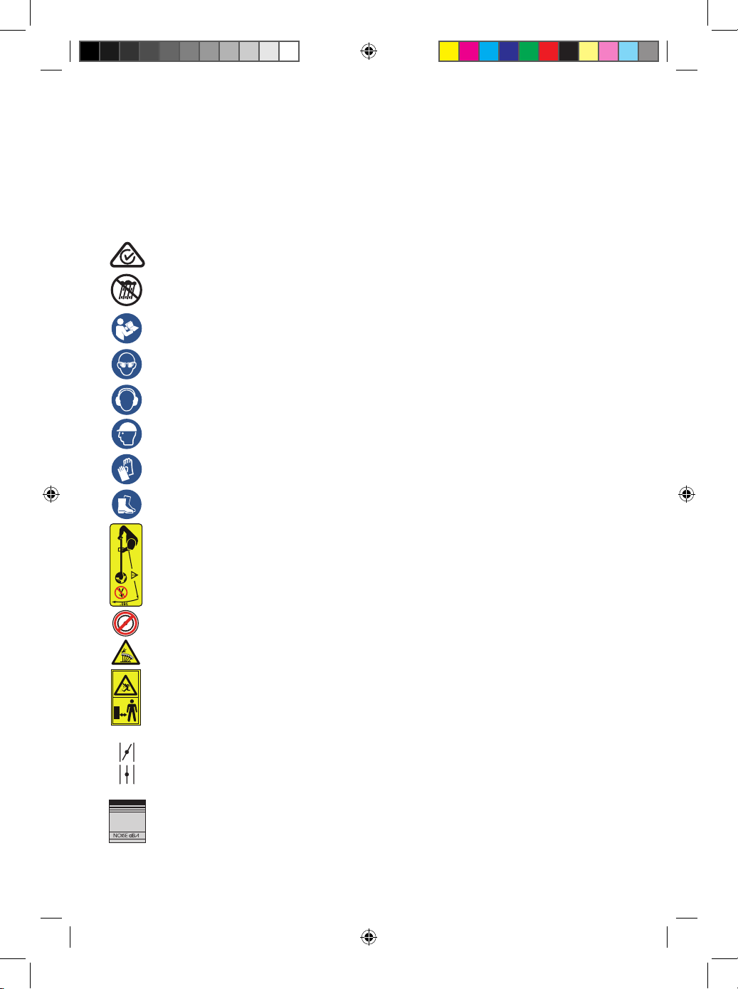
Description of symbols
The instruction manual or rating plate on your product may show symbols.
These represent important information about the product or instructions
on its use.
Conforms to relevant standards for electromagnetic compatibility.
Do not put in water.
Read these instructions for use carefully.
Wear eye protection.
Wear hearing protection.
Wear headwear protection.
-
Wear safety gloves.
Wear safety footwear.
Keep children and bystanders away while operating
Sharp blade; Risk of hand and feet injuries.
Thrown objects and rotating line can cause severe injury.
Do not operate the unit without the safety guard in place.
Keep away from rotating cutter.
Use at a distance of at least 15m from other people.
Choke control
Start position (choke closed).
Run position (choke open).
Noise label rating 80dBA (taken at 7.5 metres)
80
you must wear ear protection at all times.
3
49290 909 BC/LT IM ED2.indd 5 8/02/2017 11:00 AM
Page 6

General safety warnings
b. Avoid body contact with grounded surfaces such as pipes, radiators,
ranges and refrigerators. There is increased risk of electric shock if your
body is grounded.
c. Do not expose power tools to rain or wet conditions. Water entering
a power tool will increase the risk of electric shock.
d. Do not abuse the cord. Never use the cord for carrying, pulling or
unplugging the power tool. Keep cord away from heat, oil, sharp edges or
moving parts. Replace damaged cords immediately.
Damaged or entangled cords increase the risk of electric shock.
e. When operating a power tool outdoors, use an extension cord suitable
for outdoor use. Use of a cord suitable for outdoor reduces the risk
of electric shock.
f. To reduce the risk of electric shock, the manufacturer recommends the
use of a residual current of 30mA or less at all times.
3. Personal safety
a. Stay alert, watch what you are doing and use common sense when
operating a power tool. Do not use a power tool while you are tired or
under the inuence of drugs, alcohol or medication. A moment of
inattention while operating power tools may result in serious
personal injury.
a. Use personal protective equipment. Always wear eye protection.
Protective equipment such as dust mask, non-skid safety shoes, hard hat,
or hearing protection will reduce personal injures.
a. Prevent unintentional starting. Ensure the switch is in the “o”
position before connecting to power source and/or battery pack,
picking up or carrying the tool. Carrying power tools with your nger on
the switch or energising power tools that have the switch on
invites accidents.
a. Remove any adjusting key or wrench before turning the power tool on.
A wrench or key left attached to a rotating part of the power tool may result
in personal injury.
a. Do not overreach. Keep proper footing and balance at all times.
This enables better control of the power tool in unexpected situations.
a. Dress properly. Do not wear loose clothing or jewellery. Keep your hair,
clothing and gloves away from moving parts. Loose clothes, jewellery or
long hair can be caught in moving parts.
a. If devices are provided for the connection of dust extraction and
collection facilities, ensure these are connected and properly used.
Use of dust collection can reduce dust-related hazards.
Intended use of the 31cc 4 Stroke Brushcutter / Line Trimmer
NOTE: This product is for private domestic DIY use only.
It is not suitable for commercial or trade use.
This Line Trimmer has been designed for trimming lawn edges and
grass around shrubs and trees.
The Brushcutter has been designed for cutting and clearing grass,
thick weeds, vegetation and shrubs.
WARNING! Read all safety warnings and all instructions.
Failure to follow the warnings and instructions may result
in electric shock, re and/or serious injury.
The word power tool used in the following warnings and
throughout this manual refers to BOTH electrical power tools
and ALSO petrol driven power tools.
This unit may not be used by people (including children) with reduced
physical, sensory or mental capacities, with a lack of experience and without
the appropriate knowledge, unless they are supervised by someone who is
responsible for their safety or have been instructed by such a person with
regard to how the unit is to be operated. Children should be supervised to
ensure that they do not play with the device.
Save all warnings and instructions for future reference
1. Work area safety
a. Keep work area clean and well lit. Cluttered or dark areas invite
accidents. Rags, cloths, cord, string and similar items should never be left
around the work area.
b. Do not operate power tools in explosive environments, such as in the
presence of ammable liquids, gases, or dust. Power tools
create sparks, which may ignite the dust or fumes.
c. Keep children and bystanders away while operating a power tool.
Distractions can cause the operator to lose control.
2. Electrical safety
a. Power tool plugs must match the outlet. Never modify the plug in any
way. Do not use any adapter plugs with grounded power tools.
Unmodied plugs and matching outlets will reduce risk of electric shock.
4
49290 909 BC/LT IM ED2.indd 6 8/02/2017 11:00 AM
Page 7

b. Avoid body contact with grounded surfaces such as pipes, radiators,
ranges and refrigerators. There is increased risk of electric shock if your
body is grounded.
c. Do not expose power tools to rain or wet conditions. Water entering
a power tool will increase the risk of electric shock.
d. Do not abuse the cord. Never use the cord for carrying, pulling or
unplugging the power tool. Keep cord away from heat, oil, sharp edges or
moving parts. Replace damaged cords immediately.
Damaged or entangled cords increase the risk of electric shock.
e. When operating a power tool outdoors, use an extension cord suitable
for outdoor use. Use of a cord suitable for outdoor reduces the risk
of electric shock.
f. To reduce the risk of electric shock, the manufacturer recommends the
use of a residual current of 30mA or less at all times.
3. Personal safety
a. Stay alert, watch what you are doing and use common sense when
operating a power tool. Do not use a power tool while you are tired or
under the inuence of drugs, alcohol or medication. A moment of
inattention while operating power tools may result in serious
personal injury.
a. Use personal protective equipment. Always wear eye protection.
Protective equipment such as dust mask, non-skid safety shoes, hard hat,
or hearing protection will reduce personal injures.
a. Prevent unintentional starting. Ensure the switch is in the “o”
position before connecting to power source and/or battery pack,
picking up or carrying the tool. Carrying power tools with your nger on
the switch or energising power tools that have the switch on
invites accidents.
a. Remove any adjusting key or wrench before turning the power tool on.
A wrench or key left attached to a rotating part of the power tool may result
in personal injury.
a. Do not overreach. Keep proper footing and balance at all times.
This enables better control of the power tool in unexpected situations.
a. Dress properly. Do not wear loose clothing or jewellery. Keep your hair,
clothing and gloves away from moving parts. Loose clothes, jewellery or
long hair can be caught in moving parts.
a. If devices are provided for the connection of dust extraction and
collection facilities, ensure these are connected and properly used.
Use of dust collection can reduce dust-related hazards.
5
49290 909 BC/LT IM ED2.indd 7 8/02/2017 11:00 AM
Page 8

General safety warnings
• Do not operate in a hazardous location. Such areas include where
there is a risk of explosion of petrol fumes, leaking gas or
explosive dust.
• Do not operate in a conned area. Exhaust gases, smoke or fumes
could reach dangerous concentrations.
• Protect your product. This Brushcutter / Line Trimmer is
NOT WEATHERPROOF and should not be exposed to direct sunlight,
high ambient temperature and damp, wet or high humidity
conditions.
• Do not smoke while refuelling. This is potentially dangerous as it may
ignite the fuel and cause an explosion.
• Take care not to spill fuel or oil. When refuelling the Brushcutter / Line
Trimmer ensure that the motor has been switched o. Prevent the
spilling of fuel as this may also ignite with the hot motor.
Never refuel whilst the engine running.
• Check for fuel leaks. Do not operate if a fuel leak is detected. Where a
fuel leak is detected, drain the tank of fuel and have the leak repaired.
• Be careful where you store the Brushcutter / Line Trimmer. Store the
Brushcutter / Line Trimmer in a dry area away from ammable liquids.
• Keep your distance. The Brushcutter / Line Trimmer emits exhaust
fumes. Ensure bystanders keep a safe distance.
• Never ll fuel tank indoors. Never ll fuel tank when engine is running
or hot. Do not smoke when lling fuel tank.
Wear eye protection.
Wear hearing protection.
Wear headwear protection.
Wear safety gloves.
Wear safety footwear.
4. Power tool use and care
a. Do not force the power tools. Use the correct power tool for your
application. The correct power tool will do the job better and safer at
the rate for which it was designed.
a. Do not use the power tool if the switch does not turn it “on” and
“o”. Any power tool that cannot be controlled with the switch is
dangerous and must be repaired.
a. Disconnect the plug from the power source and/or the battery
pack from the power tool before making any adjustments,
changing accessories, or storing power tools. Such preventive
safety measures reduce the risk of starting the power tool accidentally.
a. Store idle power tools out of the reach of children and do not
allow persons unfamiliar with the power tool or these instructions
to operate the power tool. Power tools are dangerous in the hands of
untrained users.
a. Maintain power tools with care. Check for misalignment or binding
of moving parts, breakage of parts and any other condition that may
aect the power tool’s operation. If damaged, have the power tool
repaired before use. Many accidents are caused by poorly maintained
power tools.
a. Keep cutting tools sharp and clean. Properly maintained cutting
tools with sharp cutting edges are less likely to bind and are easier
to control.
a. Use the power tool, accessories and tool bits etc. in accordance
with these instructions, taking into account the working
conditions and the work to be performed. Use of the power tool for
operations dierent from those intended could result in a hazardous
situation.
6
49290 909 BC/LT IM ED2.indd 8 8/02/2017 11:00 AM
Page 9

Additional Safety Rules for Petrol Products
• Do not operate in a hazardous location. Such areas include where
there is a risk of explosion of petrol fumes, leaking gas or
explosive dust.
• Do not operate in a conned area. Exhaust gases, smoke or fumes
could reach dangerous concentrations.
• Protect your product. This Brushcutter / Line Trimmer is
NOT WEATHERPROOF and should not be exposed to direct sunlight,
high ambient temperature and damp, wet or high humidity
conditions.
• Do not smoke while refuelling. This is potentially dangerous as it may
ignite the fuel and cause an explosion.
• Take care not to spill fuel or oil. When refuelling the Brushcutter / Line
Trimmer ensure that the motor has been switched o. Prevent the
spilling of fuel as this may also ignite with the hot motor.
Never refuel whilst the engine running.
• Check for fuel leaks. Do not operate if a fuel leak is detected. Where a
fuel leak is detected, drain the tank of fuel and have the leak repaired.
• Be careful where you store the Brushcutter / Line Trimmer. Store the
Brushcutter / Line Trimmer in a dry area away from ammable liquids.
• Keep your distance. The Brushcutter / Line Trimmer emits exhaust
fumes. Ensure bystanders keep a safe distance.
• Never ll fuel tank indoors. Never ll fuel tank when engine is running
or hot. Do not smoke when lling fuel tank.
Wear eye protection.
Wear hearing protection.
Wear headwear protection.
Wear safety gloves.
Wear safety footwear.
7
49290 909 BC/LT IM ED2.indd 9 8/02/2017 11:00 AM
Page 10

Additional Safety Rules for Petrol Line Trimmers.
• Never use blades near footpaths, fencing, posts, buildings or other
immovable objects.
• Never use a blade after hitting a hard object without rst inspecting
it for damage. Do not use if any damage is detected.
• The unit is used as a scythe, cutting from the right to the left in a
broad sweeping action from side to side.
• Always wear goggles, earmus and a dusk mask when using the
Brushcutter.
• Only use blades with a cutting diameter of 255mm and a bore size
of 25.4 mm.
• Only use the Brushcutter with the correctly supplied and tted
Brushcutter guard.
• Keep bystanders a minimum of 15 metres from the operation of the
Brushcutter.
• Prior to operation, ensure the assembled Brushcutter is checked for
loose components and the operating controls of the Brushcutter.
Do not use the Brushcutter if the controls are not in perfect working
order. Ensure all nuts, bolts and clamps are all tight.
• Check the blade is correctly seated and the blade nut is tight.
• DO NOT substitute the blade with any other types of blade other than
that is detailed in this manual. DO NOT t a saw blade to this product.
• This brushcutter is tted with a centrifugal clutch. At idle, the blade
must not be rotating. Make a practice to always check the clutch is
correctly operating and at idle the blade does not rotate, and rotation
of the blade only occurs as the speed of the motor is increase from
manually operating the speed trigger.
Do NOT use the brushcutter if the blade at idle speed is rotating and
take it to an authorised service centre.
• Exercise extreme caution when using the 3T brushcutter blade with
this unit. Blade thrust is the reaction which may occur when the
spinning 3T brushcutter blade contacts anything it cannot cut.
This contact may cause the 3T brushcutter blade to stop for an instant,
and suddenly “thrust” the unit away from the object that was hit.
This reaction can be violent enough to cause the operator to lose
control of the unit. Blade thrust may occur without warning if the
blade snags, stalls or binds. This is more then likely to occur in areas
where it is dicult to see the material being cut.
• Follow all sections of the Additional Safety Rules for Petrol Products.
• Always wear goggles, earmus and a dusk mask when using the Line
Trimmer.
• Only use the length and diameter of nylon cutting line as detailed in
this manual. Never use any other cutting material.
• Never use the Line Trimmer without the supplied and correctly
tted guard.
• Ensure the line trimming blade is in good order to ensure the correct
length of cutting line is maintained.
• Keep bystanders at least 5 metres away from the operating the Line
Trimmer.
• During operation, always hold the Line Trimmer with both hands,
and make use of the Double Shoulder Strap Harness.
• Maintain a rm footing. Wear suitable fully enclosed footwear.
• Always turn o the petrol motor when making adjustments to the
cutting head or line, when cleaning, or performing any maintenance
tasks.
• When operating the Line Trimmer, be aware of the ground where the
Line Trimmer is being operated. The cutting head and line is designed
to trim grass and similar undergrowth, and stones and foreign matter
should be avoided.
• Prior to operation, ensure the assembled line Line Trimmer is checked
for loose components and the operating controls of the trimmer.
Do not use the Line Trimmer if the controls are not in perfect working
order. Ensure all nuts, bolts and clamps are all tight.
Additional Safety rules for Petrol Brushcutters
WARNING: Extreme care must be taken when using blades to ensure
safe operation. Read the safety information for safe operation using
the blade.
• Follow all sections of the Additional Safety Rules for Petrol Products.
• Always hold Brushcutter with both hands when operating. Use a rm
grip on both handles.
• Maintain your grip and balance on both feet. Position yourself so that
you will not be drawn o balance by the kick-back reaction of the
cutting blade.
• Inspect and clear the area of any hidden objects such as glass, stones,
concrete, fencing, wire, wood, metal, etc.
8
49290 909 BC/LT IM ED2.indd 10 8/02/2017 11:00 AM
Page 11

• Never use blades near footpaths, fencing, posts, buildings or other
immovable objects.
• Never use a blade after hitting a hard object without rst inspecting
it for damage. Do not use if any damage is detected.
• The unit is used as a scythe, cutting from the right to the left in a
broad sweeping action from side to side.
• Always wear goggles, earmus and a dusk mask when using the
Brushcutter.
• Only use blades with a cutting diameter of 255mm and a bore size
of 25.4 mm.
• Only use the Brushcutter with the correctly supplied and tted
Brushcutter guard.
• Keep bystanders a minimum of 15 metres from the operation of the
Brushcutter.
• Prior to operation, ensure the assembled Brushcutter is checked for
loose components and the operating controls of the Brushcutter.
Do not use the Brushcutter if the controls are not in perfect working
order. Ensure all nuts, bolts and clamps are all tight.
• Check the blade is correctly seated and the blade nut is tight.
• DO NOT substitute the blade with any other types of blade other than
that is detailed in this manual. DO NOT t a saw blade to this product.
• This brushcutter is tted with a centrifugal clutch. At idle, the blade
must not be rotating. Make a practice to always check the clutch is
correctly operating and at idle the blade does not rotate, and rotation
of the blade only occurs as the speed of the motor is increase from
manually operating the speed trigger.
Do NOT use the brushcutter if the blade at idle speed is rotating and
take it to an authorised service centre.
• Exercise extreme caution when using the 3T brushcutter blade with
this unit. Blade thrust is the reaction which may occur when the
spinning 3T brushcutter blade contacts anything it cannot cut.
This contact may cause the 3T brushcutter blade to stop for an instant,
and suddenly “thrust” the unit away from the object that was hit.
This reaction can be violent enough to cause the operator to lose
control of the unit. Blade thrust may occur without warning if the
blade snags, stalls or binds. This is more then likely to occur in areas
where it is dicult to see the material being cut.
9
49290 909 BC/LT IM ED2.indd 11 8/02/2017 11:00 AM
Page 12
31cc Brushcutter / Line Trimmer
AFTER SALES SUPPORT
e-mail: [email protected]
1800 909 909
MODEL: №. BC35TS-2 • 49290
(toll free)
AFTER SALES SUPPORT
(toll free)
31cc Brushcutter / Line Trimmer
Parts List
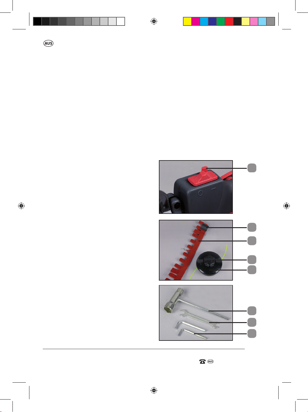
1. Spark plug
2. Recoil starter
3. Air lter cover
4. Motor housing
5. Fuel tank cap
6. Fuel tank
7. Start Trigger Lock button
8. Throttle trigger
9. Safety lever
10. On/O switch
11. Upper shaft
12. J Handle
13. Shaft locking lever
14. Shaft locking knob
15. Lower shaft
16. Guard attachment clamp
(+2 x screws & washers)
17. Brushcutter guard
18. Lower shaft gearbox
19. Spindle lock entry hole
20. Spindle
21. Inner bush with spindle hole
22. Choke lever (Red lever)
23. Priming bulb
24. Oil reservoir/ dipstick
25. Screw holes for Brushcutter guard
26. Blade nut
27. Protector
28. 3T Brushcutter blade
29. Outer ange
30. Inner ange
31. Double shoulder strap harness
32. Cut o knife
33. Clip-on Line trimmer
guard attachment
34. Bump knob
35. Spool & Line Assembly
36. Spark Plug Spanner /
Blade nut wrench /
Screwdriver combination
37. 2 x Allen key - 5mm & 4mm
38. Double shoulder strap
attachment point
39. Fuel tank bracket (not shown)
40. Air Filter
41. Air lter locking knob
42. Main Handle
43. J Handle clamp
44. 10mm Spanner
7
32
33
34
35
36
44
37
10
49290 909 BC/LT IM ED2.indd 10 8/02/2017 11:00 AM
Page 13

AFTER SALES SUPPORT
(toll free)
31cc Brushcutter / Line Trimmer
e-mail: [email protected]1800 909 909
MODEL: №. BC35TS-2 • 49290
1
2
5
4
3
6
23
24
19
20
21
13
22
42
10
43
15
2
7
9
8
11
38
12
14
25
25
30
29
28
27
26
17
3141
16
18
40
11
49290 909 BC/LT IM ED2.indd 11 8/02/2017 11:00 AM
Page 14

31cc Brushcutter / Line Trimmer
AFTER SALES SUPPORT
e-mail: [email protected]
1800 909 909
MODEL: №. BC35TS-2 • 49290
(toll free)
AFTER SALES SUPPORT
(toll free)
31cc Brushcutter / Line Trimmer
Operation of the Brushcutter / Line Trimmer
Adding and Checking the oil
IMPORTANT: The motor of this brushcutter / line trimmer is packed with NO
OIL in the motor. Prior to starting the motor, oil MUST be added to the oil
reservoir (24). Failure to add sucient oil will result in damage to the motor
which is NOT covered under the warranty of the unit.
NOTE: This is a 4 stroke brushcutter / line trimmer. The motor sump MUST
be lled with 70mL of SAE 10W/30 BEFORE starting. Fresh unleaded fuel
must be used in this unit. Do not use ethanol based fuels.
Do NOT mix oil with fuel. Oil must be separately poured into the sump of
the motor as follows, and also the oil level MUST be checked every time the
line trimmer / brushcutter is used.
NEVER attempt to remove the oil dipstick (24) while the motor is running.
ENSURE the motor is not running when the oil level is being checked.
On a new unit, the motor needs to be lled with 70mL of SAE 10W/30
engine oil.
To initially ll with oil or to check the oil level,
follow the process below.
1. Lay the unit down so that the fuel tank bracket
(39) is resting on a secure surface, or on the
ground. Clean the area directly around the oil
reservoir (24) (Fig. A).
2. Clean the area directly around the oil dipstick
(24), and then fully remove/unthread the oil
dipstick in an anti clockwise direction.
3. On a new unit which has not previously been
lled with oil, measure 70mL of SAE 10W/30 oil
and pour into the oil reservoir (24) where the
dipstick was removed.
4. Clean the dipstick portion of any oil residue and
then insert the dipstick fully into the reservoir,
however, DO NOT THREAD the dipstick into the
reservoir. Hold the dipstick in place for a few
second and then remove (Fig B).
A.
B.
12
49290 909 BC/LT IM ED2.indd 12 8/02/2017 11:00 AM
Page 15

AFTER SALES SUPPORT
(toll free)
31cc Brushcutter / Line Trimmer
e-mail: [email protected]1800 909 909
MODEL: №. BC35TS-2 • 49290
5. Check the oil mark on the dipstick (24). If the
oil level is near or below the lower limit mark
on the dipstick (Fig C), oil should be added in
small increments, into the oil reservoir, and
repeat steps 3,4 & 5 until it is up to the bottom
edge of the oil reservoir (Fig D). Be careful not to
overll or add oil past the bottom edge of the
oil reservoir.
6. IMPORTANT: The motor should NEVER be
started if the oil level is below the low oil mark.
Always check the oil level before starting
ensuring the brushcutter / line trimmer is
positioned as per step 1 for checking.
7. When the oil level is at the upper oil level mark;
the bottom edge of the oil reservoir (Fig D),
replace the dipstick and thread in the dipstick in
a clockwise direction until the dipstick is rmly
in place. The Sealing O ring on the shoulder of
the dipstick should be fully compressed when
the dipstick is rmly hand tightened.
C.
LOWER
MARK
D.
UPPER
MARK
13
49290 909 BC/LT IM ED2.indd 13 8/02/2017 11:00 AM
Page 16
31cc Brushcutter / Line Trimmer
AFTER SALES SUPPORT
e-mail: [email protected]
1800 909 909
MODEL: №. BC35TS-2 • 49290
(toll free)
AFTER SALES SUPPORT
(toll free)
31cc Brushcutter / Line Trimmer
User Instructions
General Assembly for use as a
Line Trimmer or Brushcutter
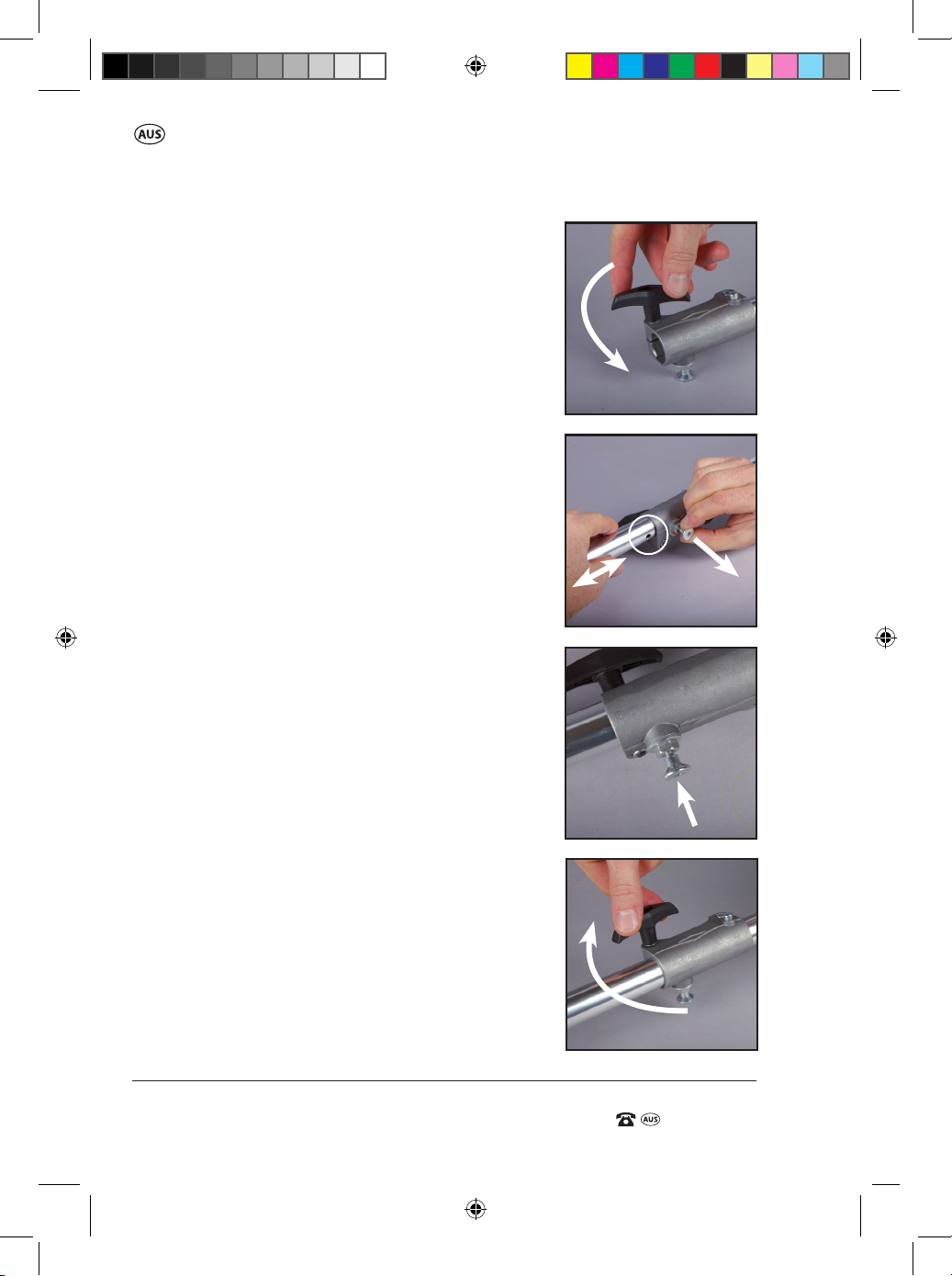
Connecting the Lower shaft
to the Upper shaft
1. Lay the unit down so that the fuel tank bracket
(39) is resting on a secure surface, or on the
ground.
2. Loosen the shaft locking lever (13) in an anti
clockwise direction (Fig. E).
3. Whilst pulling out the shaft locking knob (14)
away from the shaft, insert the lower shaft into
the upper shaft, and when the shaft has entered
approx. 3cm, release the shaft locking knob
(14).
4. Rotate the shaft up and down slightly (Fig F)
until the hole in the lower shaft engages with
the shaft locking knob (14). You will hear a click
when it locks into place (Fig. G).
NOTE: Ensure you check that the lower shaft
cannot be pulled outwards when the lock is
correctly engaged.
4. When the shaft is located, tighten the shaft
locking lever (13) to secure both shafts in place
(Fig. H).
E.
F.
G.
Click
H.
14
49290 909 BC/LT IM ED2.indd 14 8/02/2017 11:00 AM
Page 17
AFTER SALES SUPPORT
(toll free)
31cc Brushcutter / Line Trimmer
e-mail: [email protected]1800 909 909
MODEL: №. BC35TS-2 • 49290
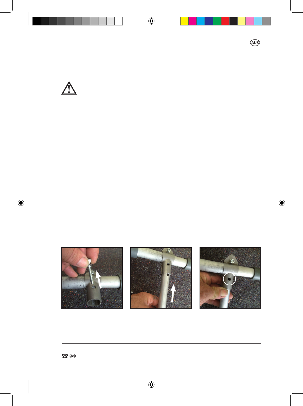
Connecting the J handle to the Upper shaft
WARNING. The J handle must be tted before use of this product.
This includes both combinations of the Brushcutter or the
Line Trimmer. Ensure the motor is NOT operating when tting
or adjusting the J handle.
NOTE:
Always ensure the engine is turned o before undertaking this task.
The J handle assembly consists of the J handle, an upper and a lower clamp,
and 2 screws, nuts & washers. The J handle clamp assembly is already tted to
the upper shaft of the brushcutter / line trimmer, in between the tted foam
sections on the upper shaft.
The gap between the two sections of foam on the upper shaft is the range up
and down the shaft that the J handle (12) can be tted.
NOTE: The J handle (12) should not be tted on any section of the main shaft.
1. Lay the unit down so the fuel tank bracket (39) is resting on a secure /
stable surface.
2. Locate the J Handle clamp (43) on the main shaft and remove the outer
longer screw in the clamp (Fig I) so the J handle (12) can fully insert into the
clamp. Do not release the screw on the opposite side.
3. Insert the J handle (12) into the J handle clamp (43) and align the hole in the
clamp with the hole through the J handle (Fig J/K).
I. J. K.
ALIGN
HOLES
15
49290 909 BC/LT IM ED2.indd 15 8/02/2017 11:00 AM
Page 18
31cc Brushcutter / Line Trimmer
AFTER SALES SUPPORT
e-mail: [email protected]
1800 909 909
MODEL: №. BC35TS-2 • 49290
(toll free)
AFTER SALES SUPPORT
(toll free)
31cc Brushcutter / Line Trimmer
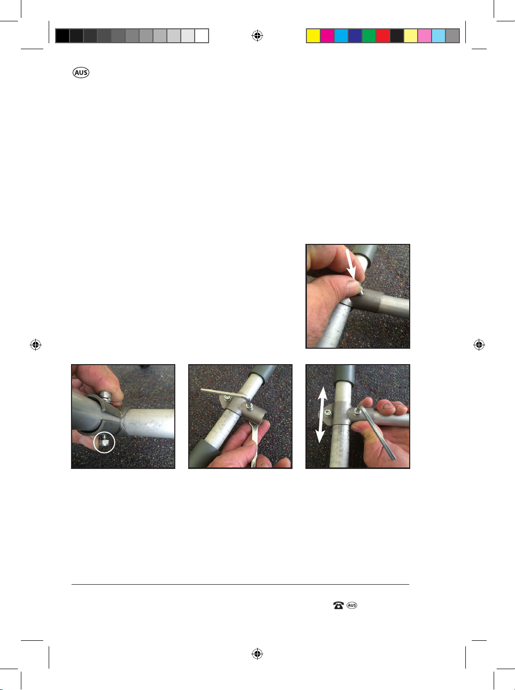
4. Replace the long screw and washers through the hole in the upper clamp,
through the J handle and through the hole in the bottom clamp (Fig L).
5. Fit the nyloc nut on the screw and tighten the nut using the supplied 10mm
spanner (44) and 5mm allen key (37). Tighten to the point where the clamp
“JUST” starts to grip the J handle (12) (Fig M/N).
6. Slide the J handle clamp (43) to the required position on the upper shaft
between the two sections of foam (Fig O).
7. Tighten fully the screw and nut which passes though the J handle (12).
The screw and nut should be tightened to the
point where the clamp fully closes around the
L.
J handle tube.
8. Check the J handle (12) is rm on the upper
shaft and does not slide or rotate.
9. If the handle does move around the upper shaft,
then proceed to tighten the smaller screw and
nut on the opposite side of the clamp to the
point where the J handle is secure.
M. N. O.
16
49290 909 BC/LT IM ED2.indd 16 8/02/2017 11:00 AM
Page 19
AFTER SALES SUPPORT
(toll free)
31cc Brushcutter / Line Trimmer
e-mail: [email protected]1800 909 909
MODEL: №. BC35TS-2 • 49290
Changing direction of the J Handle.
If the J handle clamp (43) is mounted on the opposite side to what you require
you need to reverse the J handle clamp (43) on the upper shaft (11) before
attempting to t the J handle (12).
1. Lay the unit down so the fuel tank bracket (39) is resting on a secure / stable
surface.
2. Locate the J handle clamp (43) on the main shaft and remove the outer
longer screw in the clamp (Fig I).
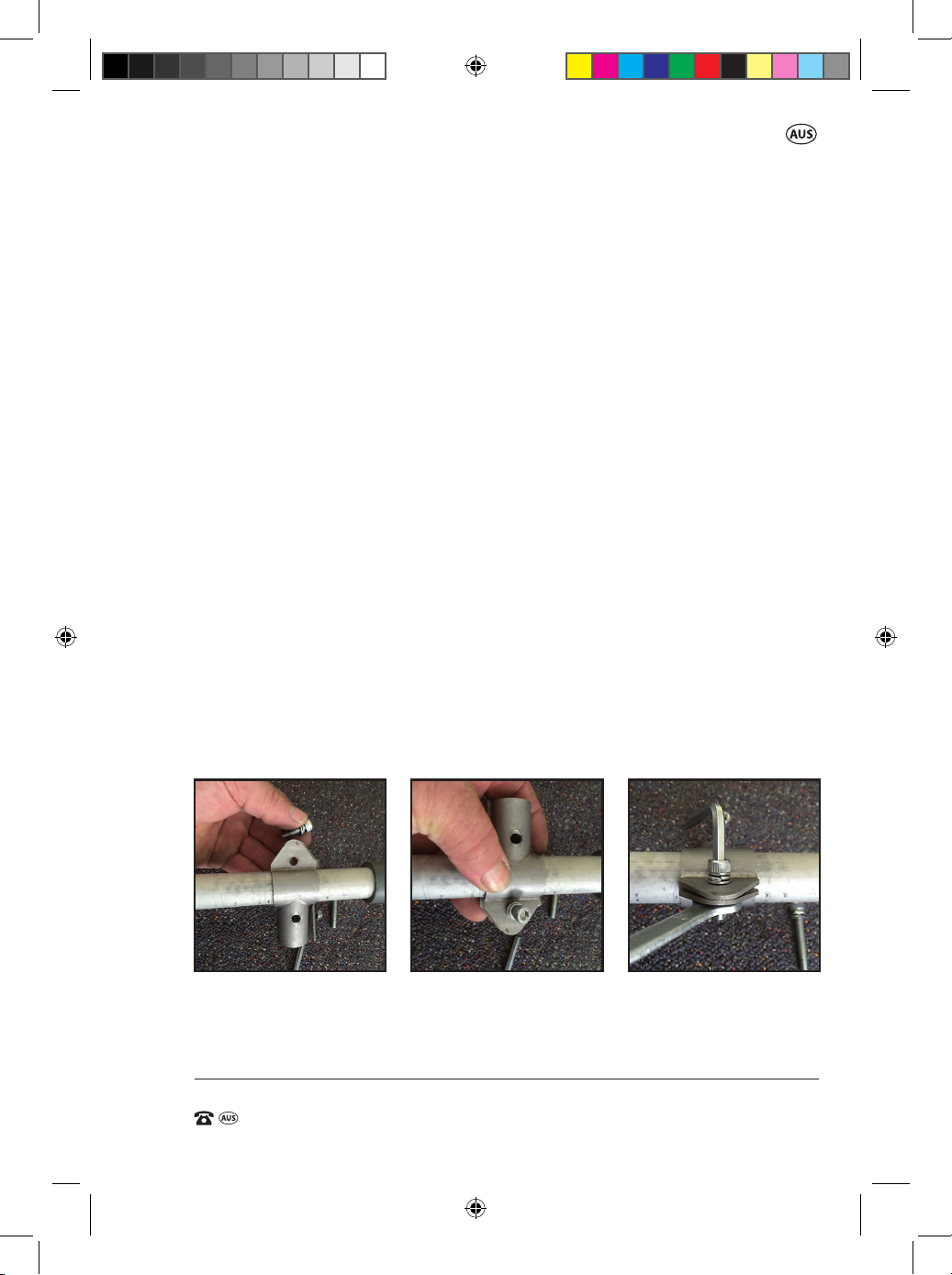
3. Remove the smaller screw and nut on the opposite side of the clamp (Fig P)
and then remove from the upper shaft the upper and lower J handle clamp
halves. Reverse the direction of the clamp halves so the J handle will mount
on the opposite side.
NOTE: Both the upper and the lower halves of the J handle clamp are the
same.
4. With the two halves of the clamp positioned around the upper shaft but
now with the entry for the J handle in the opposite direction, t the small
screw and washers through the clamp on the opposite side to where the J
handle (12) will be located (Fig Q).
5. Secure the screw with the nut and tighten until the clamp just starts to
touch each other (Fig R). Then proceed to follow the instructions from point
3 in the previous section “Connecting the J handle to the Upper shaft”.
P. Q. R.
17
49290 909 BC/LT IM ED2.indd 17 8/02/2017 11:00 AM
Page 20
31cc Brushcutter / Line Trimmer
AFTER SALES SUPPORT
e-mail: [email protected]
1800 909 909
MODEL: №. BC35TS-2 • 49290
(toll free)
AFTER SALES SUPPORT
(toll free)
31cc Brushcutter / Line Trimmer
Adjusting the J handle
The J handle (12) can be adjusted up and down the main upper shaft between
the foam tubes. The handle can also be rotated around the main shaft to suit
various operating conditions and comfort.
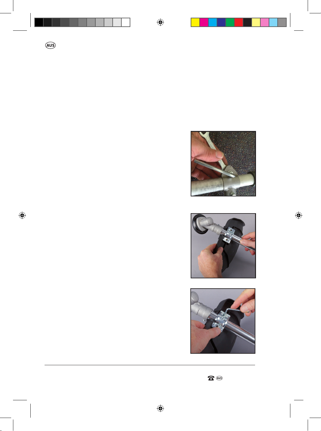
1. Loosen the small screw and nut on the J handle clamp using the supplied
5mm allen key (37) and 10mm spanner (44) (Fig S). Do not loosen the screw
and nut passing through the J handle (12).
2. Slide / rotate the J handle (12) and clamp (43)
S.
around or up or down the upper shaft. When the
desired position is achieved, tighten the smaller
screw and nut rmly to lock the clamp into
position.
3. Check the handle and clamp is rmly clamped
in position.
Fitting the Brushcutter /
Line Trimmer Guard
Before using either the Brushcutter or Line
Trimmer, the Brushcutter Guard needs to be
assembled.
1. Lay the unit down so that the fuel tank bracket
(39) is resting on a secure surface, or on the
ground.
2. Place the brushcutter guard (17) on the
underside of the lower shaft (15) so that the
2 holes on the guard line up with the 2 screw
holes on the brushcutter bracket (Fig T).
3. Once the 2 screw holes are aligned, insert the
2 screws; one on each side of the guard clamp,
and using the supplied 5mm allen key (37)
tighten in a clockwise direction until secure
(Fig. U).
T
U.
18
49290 909 BC/LT IM ED2.indd 18 8/02/2017 11:00 AM
Page 21

AFTER SALES SUPPORT
(toll free)
31cc Brushcutter / Line Trimmer
e-mail: [email protected]1800 909 909
MODEL: №. BC35TS-2 • 49290
Re shoot Image
If proceeding to use as the brushcutter, the 3T brushcutter blade (28)
needs to be assembled.
Refer to the “Fitting the Brushcutter Blade instructions” (on page 20).
If proceeding to use the line trimmer, the clip-on line trimmer guard
attachment (33) and spool and line assembly (35) requires assembly.
Refer to the “Fitting the Clip-on Guard Attachment to the Line Trimmer”
on pages 23/24 and “Fitting the Spool and Line assembly on the Line
Trimmer” on pages 24/25 for these instructions.
Fitting & Adjusting the Double Strap Shoulder Harness
WARNING. The Double strap shoulder harness (31) must be tted
before use of the product (Fig V). This includes both combinations of
the brushcutter or the line trimmer.
1. Place the shoulder straps over each shoulder so that the 2 padded shoul-
der straps are located on your front side (Fig. W), with the square black
plastic support where the straps interweave, located on your back. (Fig. X)
V.
W.
X.
19
49290 909 BC/LT IM ED2.indd 19 8/02/2017 11:00 AM
Page 22
31cc Brushcutter / Line Trimmer
AFTER SALES SUPPORT
e-mail: [email protected]
1800 909 909
MODEL: №. BC35TS-2 • 49290
(toll free)
AFTER SALES SUPPORT
(toll free)
31cc Brushcutter / Line Trimmer
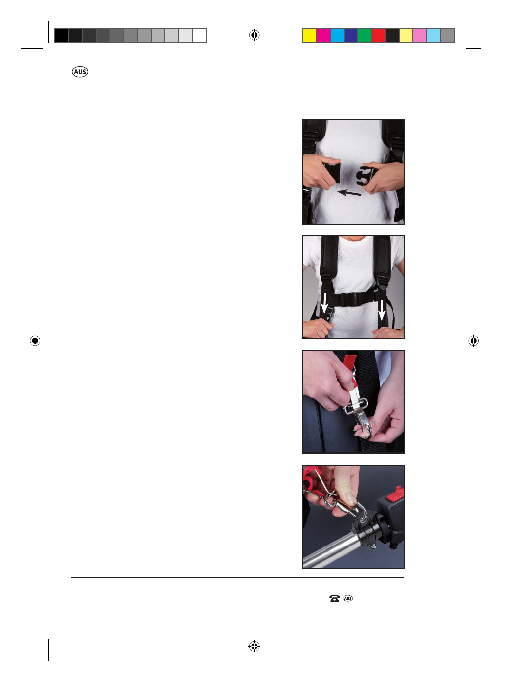
2. Connect the clip at the front to secure the double
strap shoulder harness (31) into position on your
body. (Fig. Y) NOTE: The side pad guard will be
located on your right hand side.
3. To adjust the double shoulder strap harness (31)
on your body, tighten or loosen the front straps
adjusters. (Fig. Z)
4. Ensure the metal connector clip is attached onto
the side pad guard correctly. When in the correct
position, the long metal tab (as shown in
Fig. AA with the arrow on it) needs to be holding
the metal connector clip in place.
5. To attach to the unit, insert the clip on the side
pad guard through the double strap shoulder
harness attachment point (37) (Fig. AB)
The location of the side pad guard can also be
changed by tightening or loosening the adjuster
on the side pad guard.
The double shoulder strap harness (31) is tted
with a quick release clip which allows rapid
removal of the appliance from the harness.
To activate the quick release clip so as to remove
the appliance, “Pull the red tab thus withdrawing the metal tab”. The attaching clip will then
release from the harness.
Y.
Z.
AA.
Fitting the Brushcutter Blade
NOTE: Always ensure the engine is turned o
before undertaking this task.
NOTE: Before tting, check the diameter of the
cutter is 255mm, and the Bore size is 25.4mm.
Do NOT
proceed if the cutter is dierent to these
specications.
20
49290 909 BC/LT IM ED2.indd 20 8/02/2017 11:00 AM
AB.
Page 23

AFTER SALES SUPPORT
(toll free)
31cc Brushcutter / Line Trimmer
e-mail: [email protected]1800 909 909
MODEL: №. BC35TS-2 • 49290
1. Lay the unit down so that the fuel tank bracket (39)
is on the ground or on a secure surface. Lift the
AC.
gearbox end of the lower shaft (15) to gain access
to the spindle (20).
2. Place the inner ange (30) over the spindle (20)
ensuring the spline on the spindle (20) aligns with
the spline in the inner ange (30). Fully seat the inner
ange (Fig AC).
3. Place the 3T brushcutter blade (28) over the spindle
AD.
(20) and locate on the raised centre of the inner
ange (30. (Fig AD) . Ensure the direction of rotation
of the blade as indicated by an arrow on the blade
corresponds with the arrow direction on the top of
the guard.
4. Place the outer ange (29) over the spindle (20) on
top of the 3T brushcutter blade (28) (Fig. AE),
followed by the protector (27).
5. Place the blade nut (26) on to the spindle (20) and thread the nut in an anti
clockwise direction all the way down to the protector (27) (Fig. AG).
6. To fully tighten the 3T brushcutter blade (28) onto the spindle (20) ensure the
3T brushcutter blade (28) is still correctly located on the inner ange (30).
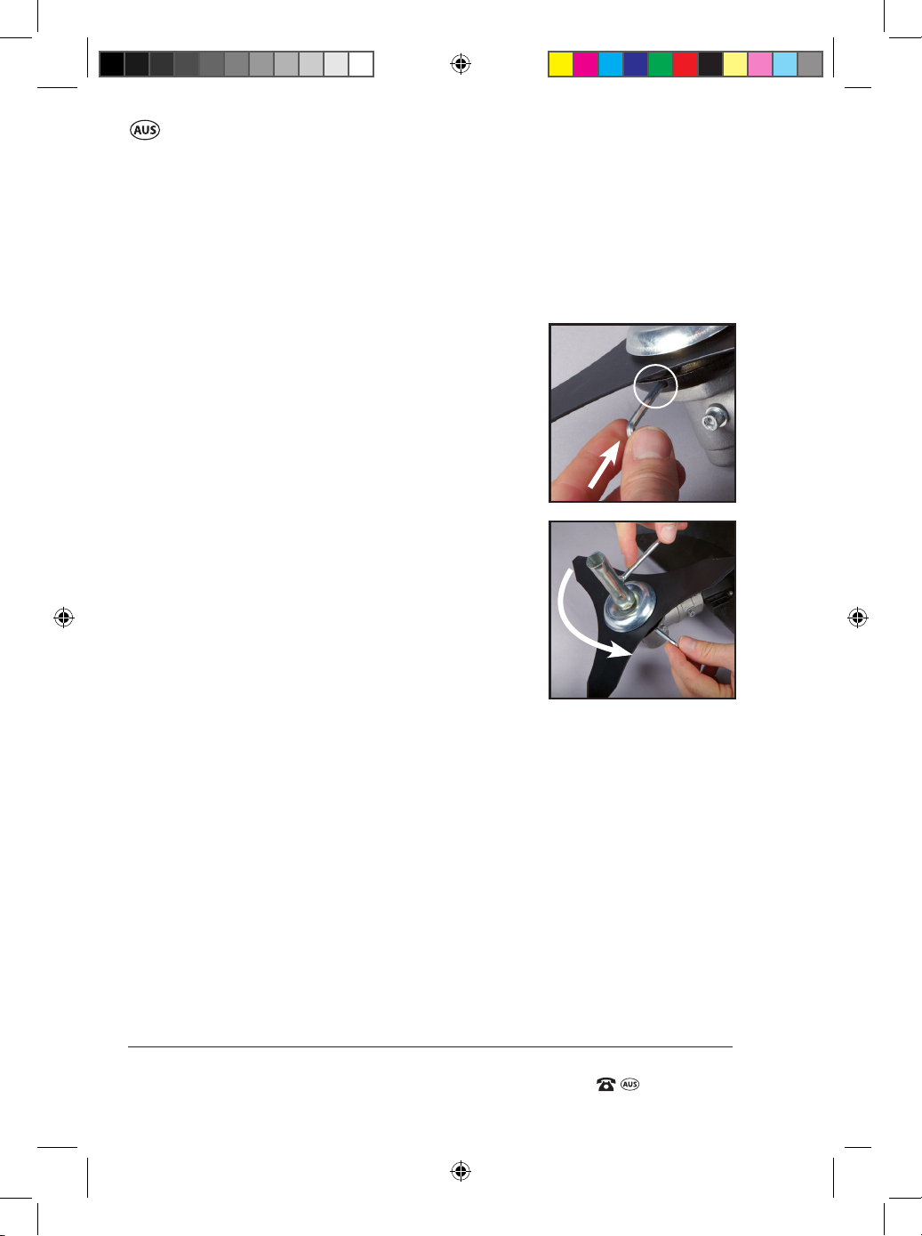
7. Insert the long end of the supplied 4mm allen key (37) through the spindle lock
hole (19) and into the hole on the inner ange (30). (This locks the spindle
allowing the blade bolt to be secured) (Fig. AH).
8. Whilst holding the supplied allen key (37) in position to lock the spindle, use the
supplied spark plug spanner / blade nut wrench / screwdriver combination (36)
AE. AF. AG.
21
49290 909 BC/LT IM ED2.indd 21 8/02/2017 11:01 AM
Page 24
31cc Brushcutter / Line Trimmer
AFTER SALES SUPPORT
e-mail: [email protected]
1800 909 909
MODEL: №. BC35TS-2 • 49290
(toll free)
AFTER SALES SUPPORT
(toll free)
31cc Brushcutter / Line Trimmer
in an anti clockwise direction to fully tighten the blade nut (26) and secure the
3T brushcutter blade (28) into position. Ensure the 3T brushcutter blade (28) is
secured tight before removing the allen key (37) from the spindle hole (Fig AI).
Changing/Removing the Brushcutter Blade
NOTE: Always ensure the engine is turned o
before undertaking this task.
1. Lay the unit down so that the fuel tank bracket
(39) is on the ground or on a secure surface. Lift
the gearbox end of the lower shaft (15) to gain
access to the output spindle (20).
2. Insert the long end of the supplied 4mm allen
key (37) through the spindle lock entry hole (19)
and into the hole on the inner ange (30).
(This locks the spindle allowing the blade bolt to
be secured) (Fig. AH).
3. Using the supplied spark plug spanner / blade
nut wrench / screwdriver combination (36),
loosen the blade nut (26) by turning in a
clockwise direction (Fig. AI).
4. Remove the blade nut (26), protector (27), outer
ange (29), and 3T brushcutter blade (28) in this
order.
NOTE: If you are removing your brushcutter blade to use the unit as a line
trimmer, refer to page 24/25 for instructions on “Fitting the Spool and Line
Assembly on the Line Trimmer”.
5. Replace with the new blade and follow steps 3-8 in the “Fitting the
Brushcutter blade” section.
AH.
AI.
Operation of the Brushcutter
To commence with operation of the brushcutter, refer to the instructions
on page 33 .
NOTE: Ensure you have lled the unit with the correct fuel and oil before
proceeding to start the unit.
NOTE: This is a 4 stroke brushcutter / line trimmer.
The motor MUST be lled with 70mL of SAE 10W/30 BEFORE starting.
Fresh unleaded fuel must be used in this unit.
Do NOT use ethanol based fuels. Do NOT mix oil with fuel.
22
49290 909 BC/LT IM ED2.indd 22 8/02/2017 11:01 AM
Page 25

AFTER SALES SUPPORT
(toll free)
31cc Brushcutter / Line Trimmer
e-mail: [email protected]1800 909 909
MODEL: №. BC35TS-2 • 49290
Tips for Operation
Always use the double shoulder strap harness (31) when using the
brushcutter to avoid serious personal injury.
Hold the brushcutter with one hand on the trigger handle and the other
hand on the J handle (12). Keep a rm grip with both hands while in
operation. The brushcutter should be held at a comfortable position with
the double shoulder strap attachment point (38) about hip height.
Maintain your grip and balance on both feet. Position yourself so that you
will not be drawn o balance by the kick-back reaction of the 3T brushcutter
blade (28).
Exercise extreme caution when using the 3T brushcutter blade (28) with
this unit. Blade thrust is the reaction which may occur when the spinning
3T brushcutter blade (28) contacts anything it cannot cut. This contact may
cause the 3T brushcutter blade (28) to stop for an instant, and suddenly
“thrust” the unit away from the object that was hit.
This reaction can be violent enough to cause the operator to lose control of
the unit. Blade thrust may occur without warning if the blade snags, stalls or
binds. This is more then likely to occur in areas where it is dicult to see the
material being cut.
For cutting ease and safety, approach the weeds being cut from the right to
the left. In the event that an unexpected object or woody stock is
encountered, this could cause the blade thrust reaction.
Specic Assembly for use as a Line Trimmer
Fitting the Clip-on Guard Attachment to the Line trimmer
NOTE: Always ensure the engine is turned o before undertaking this task.
Always use the double shoulder strap harness (31) when using the line
trimmer to avoid serious personal injury.
NOTE: the clip-on line trimmer guard attachment (33) must be secured to
the brushcutter guard (17) before ANY line trimming work is undertaken.
NOTE: Always ensure the engine is turned o before undertaking
this assembly.
WARNING: There is a cut o knife (32) on the clip-on line trimmer
guard attachment (33). Use gloves to t the clip-on line trimmer
guard attachment (33) to avoid injury.
23
49290 909 BC/LT IM ED2.indd 23 8/02/2017 11:01 AM
Page 26

31cc Brushcutter / Line Trimmer
AFTER SALES SUPPORT
e-mail: [email protected]
1800 909 909
MODEL: №. BC35TS-2 • 49290
(toll free)
AFTER SALES SUPPORT
(toll free)
31cc Brushcutter / Line Trimmer
1. Lay the unit down so that the fuel tank bracket
(39) is on the ground or on a secure surface.
Lift the gearbox end of the lower shaft (15) to
gain access to the output spindle (20).
2. Line up the tabs on the clip-on line trimmer
guard attachment (33) with the large slots on the
brushcutter guard (17). There are 2 main release
clips; one on each end of the clip-on line
trimmer guard attachment (33). This needs to
line up with the large slots on the brushcutter
guard (17) (Fig AJ).
3. When all tabs are lined up in position, push the
tabs on the clip-on line trimmer guard
attachment (33) into the slots, and the release
clips into the large slots. You will hear clicks
when the release clips are secure. (Fig. AK)
NOTE: Before using the line trimmer, remove the
cut o blade protector. After using the line
trimmer, it is recommended to replace the
blade protector.
4. To fully secure the clip-on line trimmer guard
attachment (33) to the brushcutter guard (17),
insert and secure the screw using the supplied
spark plug spanner / blade nut wrench /
screwdriver combination (36), using the
screwdriver end of the tool. Secure until tight (Fig AL).
AJ.
AK.
AL.
Fitting the Spool and Line Assembly on the Line Trimmer
NOTE: If the unit has been used as a brushcutter rst, the brushcutter blade
will need to be removed before tting the spool and line assembly.
Refer to “Changing/Removing the Brushcutter Blade” for instructions on how
to remove the blade on page 22.
NOTE: Always ensure the engine is turned o before undertaking this assembly.
1. Lay the unit down so that the fuel tank bracket (39) is on the ground or on
a secure surface. Lift the gearbox end of the lower shaft (15) to gain access
to the spindle (20).
24
49290 909 BC/LT IM ED2.indd 24 8/02/2017 11:01 AM
Page 27
AFTER SALES SUPPORT
(toll free)
31cc Brushcutter / Line Trimmer
e-mail: [email protected]1800 909 909
MODEL: №. BC35TS-2 • 49290
IMPORTANT: Ensure the inner ange is mounted on the spindle of the line
trimmer. The outer ange (29), the protector (27), the 3T brushcutter blade
(28) and the blade nut (26) are NOT required when the line trimmer spool
& line assembly (35) is being tted.
Keep these components in a safe place. The 3T
AM.
brushcutter blade (28) should be placed back in
the cardboard packaging/envelope.
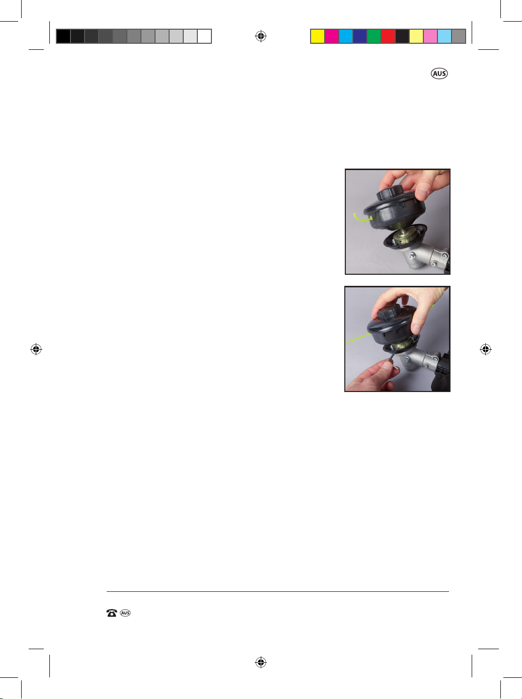
2. Place the spool and line assembly (35) on the
spindle (20) and thread on to the spindle nger
tight in an anti clockwise direction all the way
down until the back of the spool makes contact
with the inner ange (30) (Fig AM),
3. Insert the long end of the supplied 4mm allen
key (37) through the spindle lock entry hole (19)
and into the hole on the inner ange (30).
AN.
(This locks the spindle allowing the spool and
line assembly (35) to be secured). Further tighten
the spool and line assembly (35) ensuring the
assembly is tight on the spindle (20) and inner
ange (30) before removing the 4mm allen key
from the spindle hole to release the spindle
being locked (Fig. AN).
Removing the Spool and Line Assembly
NOTE: Always ensure the engine is turned o before undertaking this assembly.
1. Lay the unit down so that the fuel tank bracket (39) is on the ground or
on a secure surface. Lift the gearbox end of the lower shaft (15) to gain
access to the output spindle (20).
2. Insert the long end of the supplied 4mm allen key (37) through the
spindle lock entry hole (19) and into the hole on the inner ange (30).
(This locks the spindle allowing the spool and line assembly to be
removed). (Fig. AN)
3. Loosen the spool and line assembly (35) in a clockwise direction until it
can be removed from the spindle (20). Remove the allen key (37) locking
the spindle (20) once the spool and line assembly (35) has been removed.
25
49290 909 BC/LT IM ED2.indd 25 8/02/2017 11:01 AM
Page 28

31cc Brushcutter / Line Trimmer
AFTER SALES SUPPORT
e-mail: [email protected]
1800 909 909
MODEL: №. BC35TS-2 • 49290
(toll free)
AFTER SALES SUPPORT
(toll free)
31cc Brushcutter / Line Trimmer
NOTE: If replacing the spool and line assembly (35) with the supplied
additional spool and line assembly, follow the “Fitting the Spool and Line Assembly on the Line Trimmer” instructions on the previous page.
If replacing just the spool line on the supplied spool and line assembly,
refer to the instructions following this section.
Changing the line only on the Spool and Line Assembly
NOTE: Always ensure the engine is turned o before undertaking this
assembly.
NOTE: The spool provided on this product is a rapid or easy wind type spool.
There is no disassembly of the spool components. The following steps will
guide you through the process.
NOTE: The spool & line assembly (35) does not need to be removed from the
lower shaft (15) of the line trimmer, however, if it is easier, it can be removed
from the lower shaft (15), especially for the rst time you re-load / re-wind
the line & become familiar with the process.
The line to suit this type of spool assembly is 2.4mm diameter line, with a
length not exceeding 2.6m.
1. Remove any existing line protruding from either eyelets in the spool
assembly (35). If there is no line left inside the spool, the line can easily
be pulled outwards from the eyelets. If the line will not pull out and is
jammed, the spool will need to be opened and the jammed line released.
Refer to the section on “Clearing a Jammed Spool” following this section.
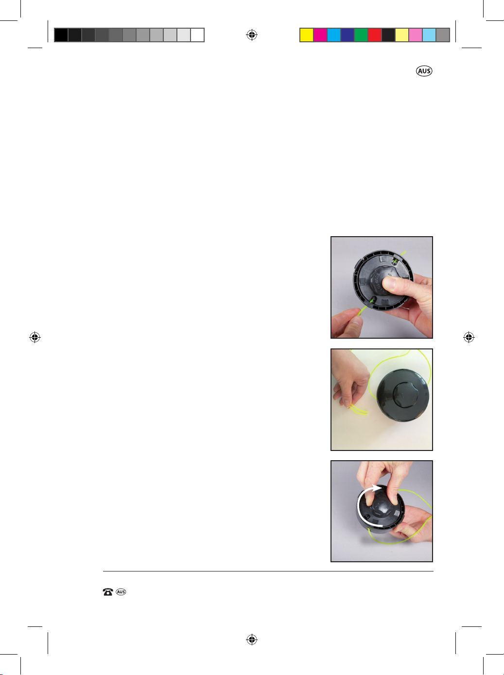
2. When looking at the top cover of the spool, there is an arrow on the
bump knob (34) pointing outward, and an arrow on the spool cover
pointing inwards, with the word “LINE” above the
arrow. Whilst holding the spool housing, rotate
the bump knob (34) in a clockwise direction (as
shown by the rotating arrow on the bump knob)
until the two outer arrows line up together (Fig
AO). Depressing the bump knob (34) slightly
while rotating can assist in rotating the bump
knob (34).
AO.
26
49290 909 BC/LT IM ED2.indd 26 8/02/2017 11:01 AM
Page 29
AFTER SALES SUPPORT
(toll free)
31cc Brushcutter / Line Trimmer
e-mail: [email protected]1800 909 909
MODEL: №. BC35TS-2 • 49290
3. Cut a length of 2.4mm diameter nylon line to a length of 2.6m, ensuring
the line is cut cleanly. If the rst 150mm of line is curved, try and
straighten the line as much as possible for entry into the spool.
4. Following the arrow direction on the spool cover, pass one end of the
nylon line through the eyelet until it passes through the spool and out
through the opposite side (Fig AP). The line should pass through the
spool with the rst 150mm of line. If it does not pass through the other
side within this line length, check the arrows align on the spool cover
and the bump knob (34). Also check if there is
a curve in the line. A straight section of line is
always better than a curved section. Remove
A P.
the line from the eyelet and retry and change
the angle of entry. Slight pressure on the bump
knob (34) my also assist, depending on the
curve on the line.
5. Pull the line through the spool so both lengths
of line extending from each eyelet are the same
length (Fig AQ).
6. Rotate the bump knob in a clockwise direction;
AQ.
also the direction of the rotation arrow on the
bump knob (34). As the bump knob (34) is
rotated, the line will be evenly be drawn into
the spool and evenly wind the line in place.
Continue to wind the line into the spool until
approx. 100mm of line extends out from the
eyelets (Fig AR).
NOTE: Slight downward pressure on the spool
will assist in the rotating action.
AR.
7. The spool and line is now ready for use. If the
spool & line assembly (35) was removed from
the lower shaft (15) for this process, ensure it is
correctly tted as per the instructions on
page 24.
CLOCKWISE
27
49290 909 BC/LT IM ED2.indd 27 8/02/2017 11:01 AM
Page 30
31cc Brushcutter / Line Trimmer
AFTER SALES SUPPORT
e-mail: [email protected]
1800 909 909
MODEL: №. BC35TS-2 • 49290
(toll free)
AFTER SALES SUPPORT
(toll free)
31cc Brushcutter / Line Trimmer
Clearing a Jammed Spool
NOTE: Always ensure the engine is turned o
before undertaking this assembly.
The spool & line assembly (35) does not need to
be removed from the lower shaft (15) of the line
trimmer, however, if it is easier, it can be removed
from the lower shaft (15) for this process.
In the case where the spool will not feed out
line when the bump knob (34) is bumped on
the ground at high speed, or the line will not
pull through when the line needs replacing, the
following process should be followed to open the
spool & line assembly (35) to check the lay of the
line on the inner spool.
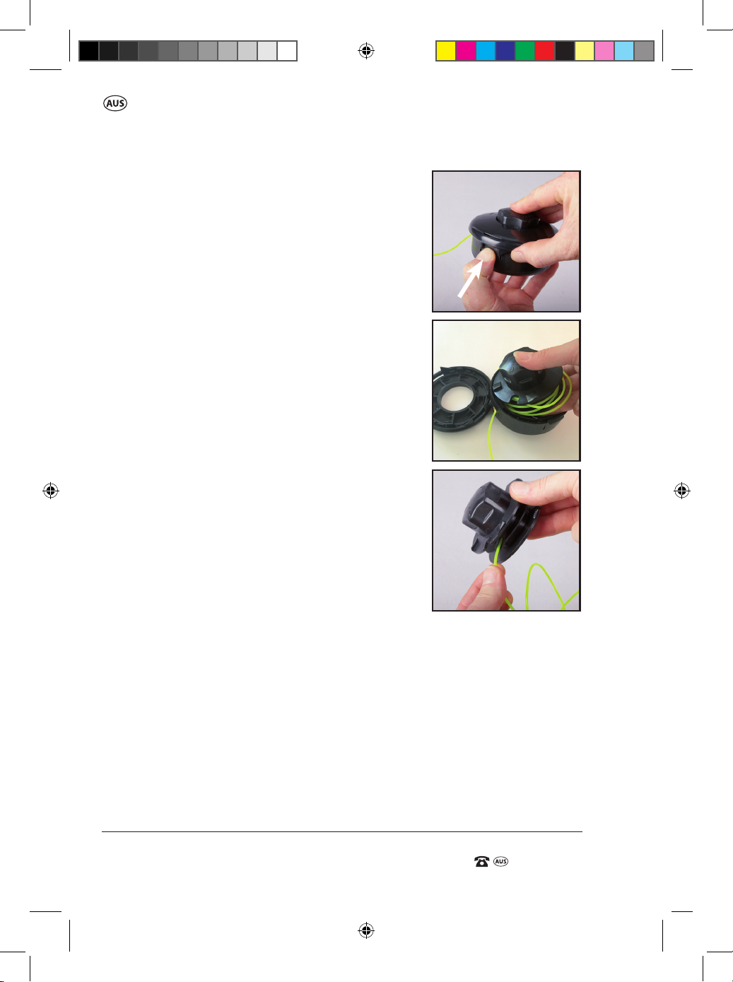
1. To open the spool & line assembly (35), press
rmly in the centre of the two securing tabs on
each side of the spool assembly (35), one at a
time (Fig AS). When pressed rmly, the spool
cover can be lifted when released. Remove the
top spool cover.
2. Remove the internal spool itself with the
jammed line, fully from the spool housing
(Fig AT).
3. Remove all the existing line from the spool
completely (Fig AU).
AS.
AT.
AU.
28
49290 909 BC/LT IM ED2.indd 28 8/02/2017 11:01 AM
Page 31
AFTER SALES SUPPORT
(toll free)
31cc Brushcutter / Line Trimmer
e-mail: [email protected]1800 909 909
MODEL: №. BC35TS-2 • 49290
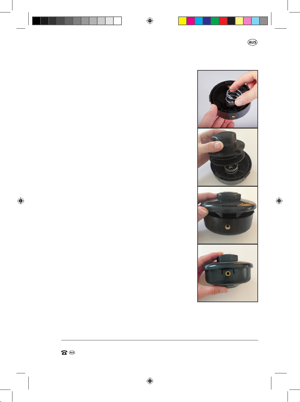
4. Reassemble the spool assembly by rstly
centralising the compression spring in the base
of the spool housing, then replacing the spool
on top of the spring followed by replacing the
spool cover on the spool (Fig AV).
NOTE: When replacing the spool cover, ensure
the clips of the spool housing align with the
spool cover. When the spool cover is located
on the spool housing, push down rmly on the
cover to ensure the clips have engaged on the
cover and the cover cannot pull o.
5. Check the removed line for damages, or use new
line. Reload new line onto the spool as per the
previous section “Changing the line only on the
Spool and Line Assembly”.
Prior to operating the line trimmer after line has
been added, it is suggested to trim the lines so
they are even and just short of the cutting blade
on the guard. This prevents a possible large
section of line being trimmed at high speed.
When you start the line trimmer, bump the head
of the spool on the ground to enable the cut o
knife on the guard to cut the line to the
required length for use.
AV.
29
49290 909 BC/LT IM ED2.indd 29 8/02/2017 11:01 AM
Page 32
31cc Brushcutter / Line Trimmer
AFTER SALES SUPPORT
e-mail: [email protected]
1800 909 909
MODEL: №. BC35TS-2 • 49290
(toll free)
AFTER SALES SUPPORT
(toll free)
31cc Brushcutter / Line Trimmer
Operation of the Line Trimmer
To start the line trimmer, refer to the instructions on page 33.
NOTE: This is a 4 stroke brushcutter / line trimmer.
The motor MUST be lled with 70mL of SAE 10W/30 BEFORE starting.
Fresh unleaded fuel must be used in this unit.
Do NOT use ethanol based fuels. Do NOT mix oil with fuel.
Use of the Line trimmer
This petrol line trimmer is only made to cut grass.
• Always use the double shoulder strap harness (31)
when using the line trimmer to avoid serious personal injury.
• Perform a few accelerations of the motor without reaching maximum
speed and without working to make sure that everything is in good
working order.
• Start the engine only when you are close to the working area.
• Place yourself in a well balanced position, stable on both feet.
Advancing the line manually
NOTE: Always ensure the engine is turned o
before undertaking this task.
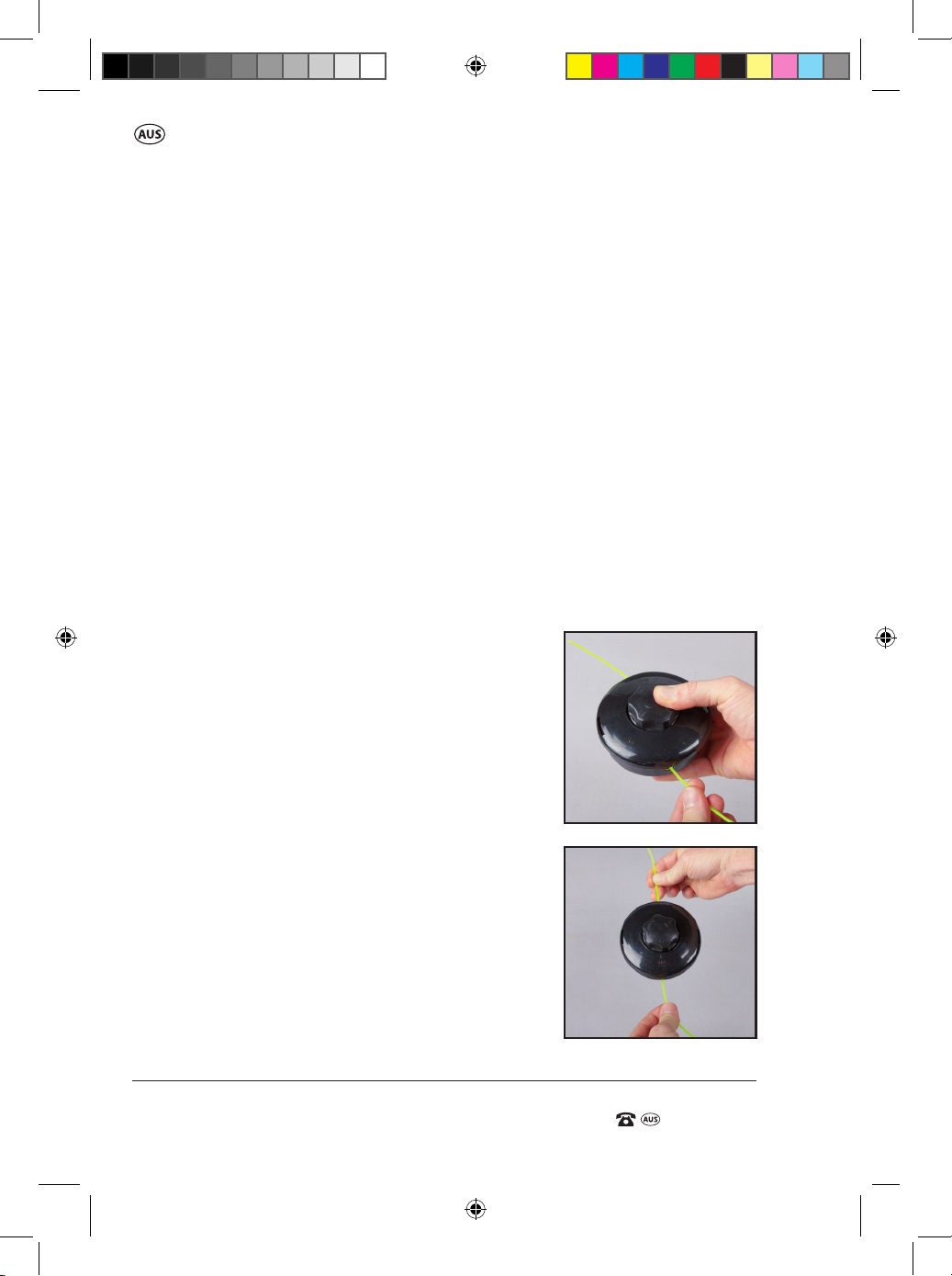
1. Push the bump knob (34) in while pulling on
both lines to manually advance the
line (Fig. AW).
2. Release the bump knob and again pull on both
lines to advance the line further (Fig. AX).
3. If the line still does not advance remove the
spool and check the lay of the line. It may be
twisted or trapped under over laying line.
AW.
AX.
30
49290 909 BC/LT IM ED2.indd 30 8/02/2017 11:01 AM
Page 33

AFTER SALES SUPPORT
(toll free)
31cc Brushcutter / Line Trimmer
e-mail: [email protected]1800 909 909
MODEL: №. BC35TS-2 • 49290
Tips for operating the Line Trimmer
IMPORTANT. Petrol line trimmers transmit vibrations to the operator during
use. These vibrations can generate increased fatigue. For this reason, we
recommend taking regular breaks during work. We also recommend taking
a break after a few hours of work to rest the engine. If abnormal noise or
vibration occurs during operation, turn the line trimmer o immediately and
have the problem corrected.
Keep a rm grip on the trimmer with both hands while in operation.
The trimmer should be held at a comfortable position with the rear handle
about hip height.
Always operate the trimmer at full throttle. Cut tall grass from the top down
to prevent grass from wrapping around the spool which may cause the
trimmer to overheat.
NOTE: If grass becomes wrapped around the spool, stop the engine,
disconnect the spark plug wire, and remove the grass.
Tips for cutting
WARNING.
Beware of bystanders at all times
• Cut the grass like you are in a corridor about 1.5m wide.
Move step by step, moving the machine from left to right and vice-versa.
Make sure at each step that you are still well balanced on your feet
• Keep the line trimmer tilted towards the area being cut
• Let the tip of the line do the cutting. Never force the spool into
uncut grass.
• Running the line into fences, stone and brick walls, curbs, and wood
causes extra line wear, even breakage.
• Do NOT run the bump knob (34) on the ground during the cutting
process. The bump knob (34) should only touch the ground when the
bump knob (34) is tapped on the ground to extend the cutting line.
31
49290 909 BC/LT IM ED2.indd 31 8/02/2017 11:01 AM
Page 34

31cc Brushcutter / Line Trimmer
AFTER SALES SUPPORT
e-mail: [email protected]
1800 909 909
MODEL: №. BC35TS-2 • 49290
(toll free)
AFTER SALES SUPPORT
(toll free)
31cc Brushcutter / Line Trimmer
Feeding the line
The line trimmer has a bump feed mechanism which releases the line
without having to stop the engine.
1. To release additional line increase the speed of the motor to no less than
half speed, then, lightly tap the bump knob (34) on the ground while
operating the unit at high speed.
NOTE: Always keep the line fully extended for optimum cutting
performance. Line release becomes more dicult as the cutting line
becomes shorter. Cutting eciency also decreases as the line
becomes shorter.
The line will not extend if the speed of the spool is not operating at least
half speed. If the line does not extend, increase the speed to full speed
while tapping the bump knob on the ground. If the line still does not
extend, stop the motor and check the line inside the spool has not tangled
and also ensure there is sucient line in the spool.
2. Each time the head is bumped it releases approximately 2cm of line.
Release the line until it strikes the cut o knife (32). This may require
several taps.
NOTE: The cut o knife (32) on the clip-on line trimmer guard attachment
(33) will automatically cut o any excess line. For best results tap the head on
hard soil or bare ground. Never bump the spool head on concrete as it may
crack the spool housing. Make sure the cut o knife (32) protector has been
removed. It is recommended to replace the protector when the line trimmer
is not in use.
IMPORTANT. Do not hit stones (even small ones), piles of earth, and small
pieces of wood or anything else that could be hidden or poorly visible in
the grass. If you hit a large object by accident, or if you jam the cutting tool
due to overloading or having the cutter jammed with grass, you must stop
the engine.
NOTE: All protective devices of the machine as well as protective equip-
ment must be maintained in good operation condition during the period
of use.
NOTE: If the line is too short you may not be able to advance the line by
tapping it on the ground. If this is the case, stop the engine and manually
advance the line.
32
49290 909 BC/LT IM ED2.indd 32 8/02/2017 11:01 AM
Page 35
AFTER SALES SUPPORT
(toll free)
31cc Brushcutter / Line Trimmer
e-mail: [email protected]1800 909 909
MODEL: №. BC35TS-2 • 49290
Operation of the Brushcutter / Line Trimmer
Fuelling
IMPORTANT: Fuel goes o after about 3-4 months. If you nd your unit does
not start, rst change the fuel in the tank with newly purchased fuel.
WARNING: Do not rell fuel tank while engine is running or is hot.
Move at least 10m away from the refuelling site before starting engine.
NOTE. Do not use fuel that contains ethanol. Use fresh unleaded fuel.
Do not smoke when refuelling or operating the product.
• Be careful not to admit dust, dirt, water or other foreign objects into
the fuel.
• Wipe o spilt fuel thoroughly before starting engine.
• Ensure you DO NOT fuel the unit in close
proximity to any open ames, lit cigarettes,
or hot objects.
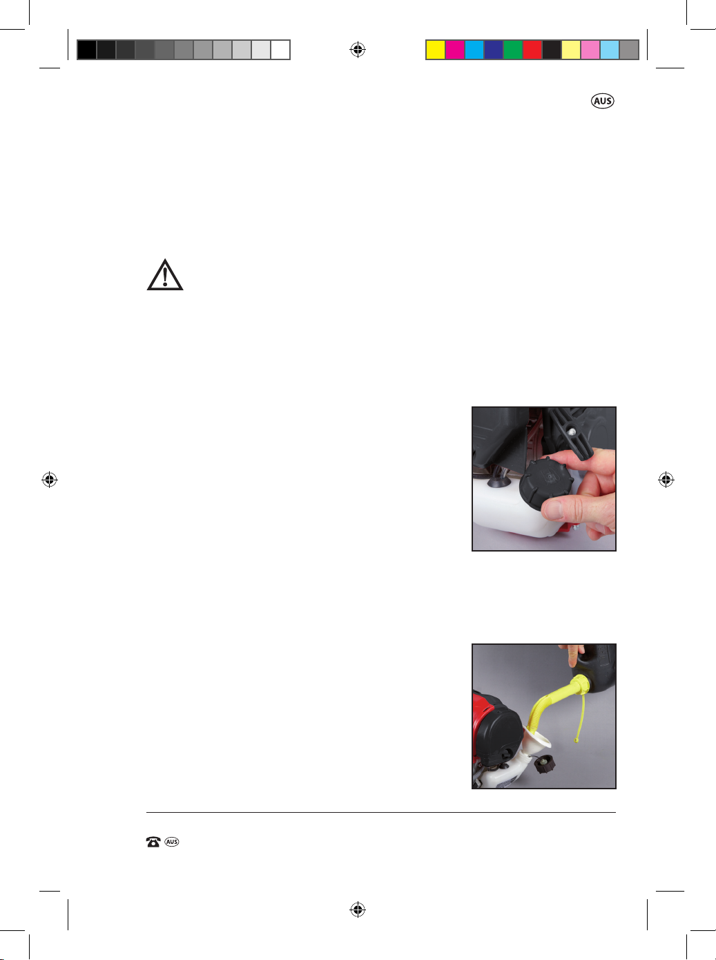
1. Unscrew the fuel tank cap (5) (Fig AY) and pour
fresh unleaded fuel into the tank with the aid
of a funnel. (Fig. AZ)
NOTE: The fuel tank capacity is 650mL.
Be careful not to spill any mixture. If this
happens, wipe the spill with a clean rag.
2. Replace the fuel cap (5) taking care NOT to cross thread the cap on the
fuel tank (6). Tighten the cap rmly in a clockwise direction.
3. When starting the engine ensure it is at least 10m away from the area
where the fuel tank has been lled up in order to avoid any risk of re.
• Always use extreme care when handling fuel!
Fuel is highly ammable.
• Never attempt to fuel the product if the fuel
system components are damaged or are
leaking.
• Never attempt to refuel the engine while it is
running or still warm, allow it to cool before
fuelling.
AY.
AZ.
33
49290 909 BC/LT IM ED2.indd 33 8/02/2017 11:01 AM
Page 36

31cc Brushcutter / Line Trimmer
AFTER SALES SUPPORT
e-mail: [email protected]
1800 909 909
MODEL: №. BC35TS-2 • 49290
(toll free)
AFTER SALES SUPPORT
(toll free)
31cc Brushcutter / Line Trimmer
• Never smoke or light any res near the product or fuels.
• Always transport and store fuels in an approved container.
• Never place ammable material close to the engine muer.
• Never operate the product without a properly functioning muer and
spark plug cover installed.
• Never operate the product unless it is properly assembled and in good
working condition.
• Do not use fuel which contains ethanol or methanol as it may damage
the fuel lines and other engine parts.
Use fresh unleaded fuel.
BA.
Starting the Brushcutter / Line Trimmer
Choke control
Start position (choke closed)
Run position (choke open)
1. Slide the on/o switch (10) to the ‘ON’ position
(towards the engine) as marked with a “I” below
the switch on the side of the handle housing
(Fig BA).
2. Move the choke (red lever) (22) (which is
located behind the air lter cover (3) housing,
and just above the fuel tank cap (5)) upwards to
the full choke or cold start position (Fig. BB).
NOTE. This is not required if the engine is
already warm.
3. Push the priming bulb (23)(which is located
above the choke lever) 6-10 times, until the
priming bulb lls with fuel mixture and excess
fuel is pumped down the bypass tube when the
bulb is pressed (Fig BC).
NOTE. For cold starting this is an important
step.
BB.
BC.
O
-
34
49290 909 BC/LT IM ED2.indd 34 8/02/2017 11:01 AM
Page 37

AFTER SALES SUPPORT
(toll free)
31cc Brushcutter / Line Trimmer
e-mail: [email protected]1800 909 909
MODEL: №. BC35TS-2 • 49290
4. Engage the start trigger lock button (7) to assist
in the motor starting. To engage the start trigger
lock button (7), depress the safety lever (9) and
then the throttle trigger (8) fully.
While these two parts are depressed, push
downward and forward and hold on the throttle
start lock button (7) (Fig BD).
Slowly release the throttle trigger (8) and the
safety lever (9) until released. The throttle start
trigger lock button (7) will be locked down and
can also be released.
5. Check the ignition on/o switch (10) is ‘ON’.
Pull the recoil starter (2) lightly until you feel
resistance then pull quickly until the engine
starts (Fig. AE) (Under full choke it may only
run for 1 or 2 seconds).
6. Push the choke (red lever) (22) half way down
and allow the motor to warm up. Restart if the
motor stops.
Do not pull the cord with a jerk or release it until
fully rewound. Provided the previous steps have
been performed, the motor should start.
As soon as the motor starts and is running,
depress the safety lever (9) and pull the throttle
trigger (8) on and then immediately release the
throttle trigger (8). This will disengage the start trigger lock button (7) and
the motor will reduce to Idle speed.
BD.
BE.
35
49290 909 BC/LT IM ED2.indd 35 8/02/2017 11:01 AM
Page 38

31cc Brushcutter / Line Trimmer
AFTER SALES SUPPORT
e-mail: [email protected]
1800 909 909
MODEL: №. BC35TS-2 • 49290
(toll free)
AFTER SALES SUPPORT
(toll free)
31cc Brushcutter / Line Trimmer
WARNING: On start up, the output spindle may rotate under load when the
start trigger lock button (7) is used so ensure the cutting device is positioned
away from other persons, animals or debris. The start trigger lock button (7)
is for assistance in starting only and must not be used during operation. On
release of the throttle trigger (8), the motor must return to the idle speed and
the blade or line must NOT be turning under drive from the motor.
7. Once the engine is fully warm ensure the choke (red lever) (22) is down fully
to the run position (warm start).
Warm Start
When re starting the unit after it has been used and the motor is hot, there is
no need to engage the choke (red lever) (22) or the start trigger lock button
(7). Follow steps 4, 5, 6 & 7 on the previous page.
A Flooded Engine
If the choke (red lever) (22) has been left in the full choke position and the
engine will not start, it is possible the engine has been ooded
(Too much fuel).
To assist to clear a ooded engine:
1. Move the choke (red lever) (22) to the run or warm start position.
2. Squeeze the safety lever (9), and pull on fully the throttle trigger (8).
3. Check the on/o switch (10) is in the “on” position as indicated by an “I”.
4. Pull the recoil starter (2) a number of times to clear the fuel and start
the motor.
WARNING. Be aware that if starting occurs with the throttle pressed,
the motor will accelerate and thus engaging the clutch, which will then
rotate the cutting head.
As soon as the motor starts release the throttle so the motor runs at
idle speed and disengages the clutch.
36
49290 909 BC/LT IM ED2.indd 36 8/02/2017 11:01 AM
Page 39
AFTER SALES SUPPORT
(toll free)
31cc Brushcutter / Line Trimmer
e-mail: [email protected]1800 909 909
MODEL: №. BC35TS-2 • 49290
Adjusting the speed on the Brushcutter / Line Trimmer
NOTE: The cutting head (spool and line) will not rotate at the idle speed.
The cutting head (spool and line) will engage and rotate when the speed of
the motor is increased.
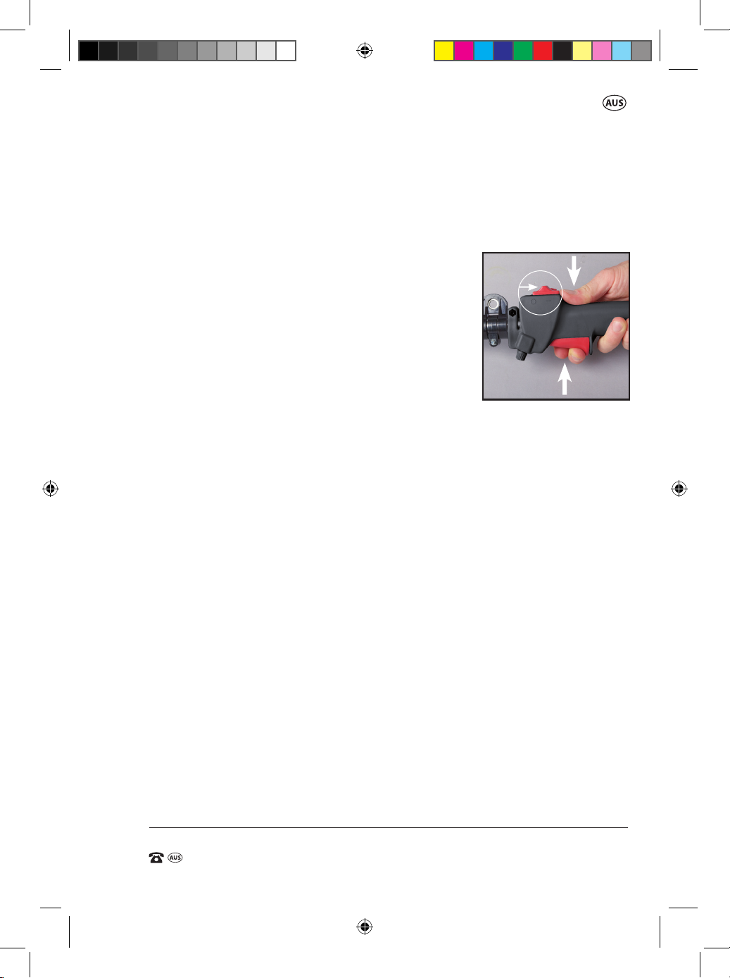
1. To increase speed and engage the cutting head,
squeeze the safety lever (9) and then throttle
trigger (8) (Fig. BF).
BF.
O
-
2. To decrease the speed, slowly release the throttle
trigger (8) to the desired speed.
3. To disengage the cutter head (spool and line),
release all pressure on the throttle trigger (8)
and allow the motor to return to idle. The cutter
head (spool and line) will disengage at idle.
NOTE: Be aware that when using the 3T brushcutter blade (28), it will take a
few seconds to run down.
IMPORTANT: If the cutting head (spool and line) does not disengage and stop
when the throttle is in the idle position, TURN OFF the petrol motor and have
the unit checked at a service centre. This should be checked EVERY time the
motor is started.
Stopping the Brushcutter/ Line Trimmer
1. Release the throttle trigger (8) and allow the engine to idle for a
few moments.
2. Slide the on/o switch (10) to the ‘OFF’ position (towards to the lower
shaft) as marked with “STOP” and a directional arrow. Also indicated on
the side of the handle housing by an “O”.
3. The engine will now stop.
37
49290 909 BC/LT IM ED2.indd 37 8/02/2017 11:01 AM
Page 40

31cc Brushcutter / Line Trimmer
AFTER SALES SUPPORT
e-mail: [email protected]
1800 909 909
MODEL: №. BC35TS-2 • 49290
(toll free)
AFTER SALES SUPPORT
(toll free)
31cc Brushcutter / Line Trimmer
Running in the engine
1. During the rst 2–3 hours of work, run the engine at a moderate RPM.
2. We advise you in any case not to maintain your engine at a high speed as
the dierent components must settle with each other during the process
of running in the engine.
3. It is at the end of the running in period that the engine will reach its
maximum power.
4. After the rst two hours of work, stop and make sure that all nuts and
screws are securely fastened, and tighten them if necessary.
Maintenance & Cleaning
WARNING. The engine of the petrol brushcutter / line trimmer must
be at a complete stop during assembling, repair and cleaning
operations that could be necessary.
General inspection
Regularly check that all the xing screws are tight. They may vibrate loose
over time.
Always check when rst starting the motor for each use that the cutting
head is not rotating under the power of the motor when the motor is at idle.
Do not perform any maintenance procedures with the motor in operation.
Ensure the motor has stopped, and the on/ o switch is in the STOP position.
The spark plug lead should be removed from the spark plug.
Only use original 909 replacement parts when component parts require
replacement.
Repairs
Repairs beyond those described above, should only be undertaken by
trained personal. Should a malfunction occur do not use the unit any further
and do not attempt to repair it yourself. Contact Customer Service or have
the unit repaired by an approved Service Agent.
38
49290 909 BC/LT IM ED2.indd 38 8/02/2017 11:01 AM
Page 41
AFTER SALES SUPPORT
(toll free)
31cc Brushcutter / Line Trimmer
e-mail: [email protected]1800 909 909
MODEL: №. BC35TS-2 • 49290
Maintenance
Air lter
Accumulated dust in the air lter will reduce engine eciency, increase fuel
consumption and allow abrasive particles to pass into the engine.
Remove the air lter as often as necessary to maintain a clean condition.
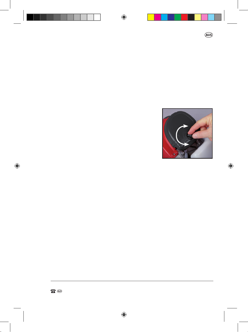
1. Remove the air lter cover (3) by completely loosening the air lter cover
locking knob (41) in an anti clockwise direction.
When the locking knob is loose enough, the air
lter cover can be removed (Fig BG).
2. Light surface dust can readily be removed by
tapping the lter. Heavy deposits should be
washed out in suitable detergent. Do not use
petrol or other chemical cleaners/solvent.
3. Squeeze out the remaining water and allow the
lter to completely dry, and replace it.
4. Replace the air lter (40) rst ensuring the 2 tabs on the top of the
surrounding housing engage with the 2 holes at the top of the air lter
cover (3). When tted back in place, secure the air lter locking knob (41)
by rotating the knob in a clockwise direction.
The air lter should be changed after approximately every 50 hours or
sooner when used in high dust environments.
Replacement air lters are available for purchase from our website
www.extrabattery.com.au. or by calling our Customer Service line
on 1800 909 909.
BG.
TIGHTEN
LOOSEN
39
49290 909 BC/LT IM ED2.indd 39 8/02/2017 11:01 AM
Page 42
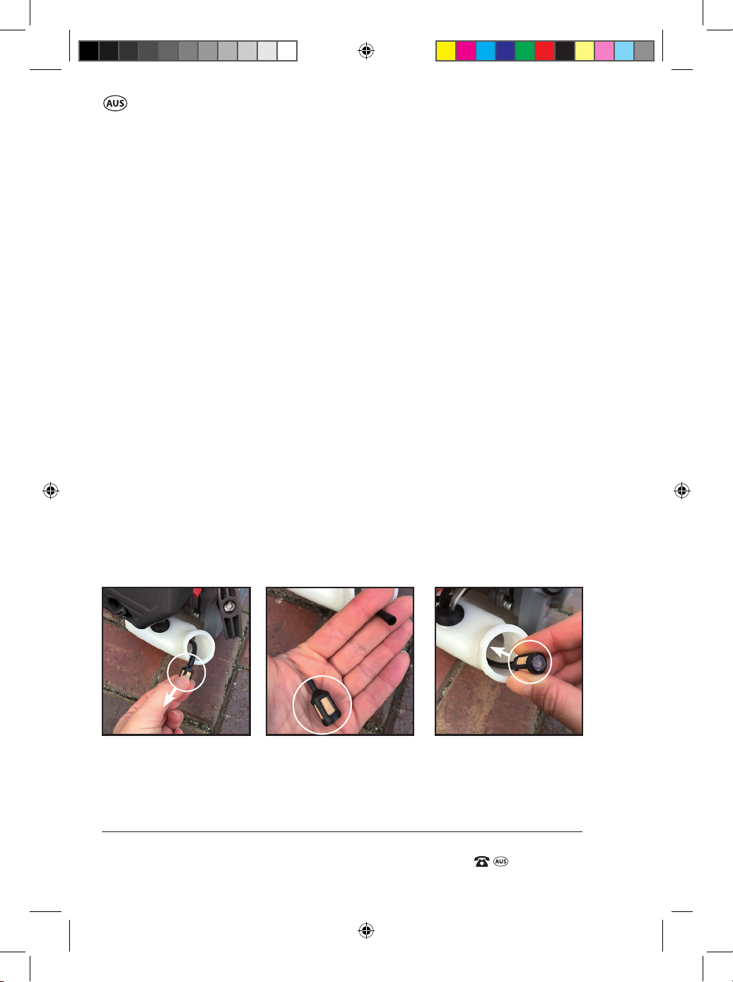
31cc Brushcutter / Line Trimmer
AFTER SALES SUPPORT
e-mail: [email protected]
1800 909 909
MODEL: №. BC35TS-2 • 49290
(toll free)
AFTER SALES SUPPORT
(toll free)
31cc Brushcutter / Line Trimmer
Fuel Filter
• The fuel tank is tted with a lter.
• Filter is situated at the free end of fuel pipe and can be picked out
through fuel port with a piece of hooked wire or the like. Once the fuel
lter is picked out from the fuel tank, pull the fuel lter o the fuel line
(Fig BH / BI).
Replace the new fuel lter by pushing it onto the fuel line until it is secure,
and then inserting the fuel lter and fuel line back into the fuel tank
(Fig BJ).
• Check the fuel lter periodically. Do not allow dust to enter the fuel tank.
Clogged lter will cause diculty when starting engine or abnormalities
in engine performance.
• When the lter is dirty, replace the lter.
• When the inside of the fuel tank is dirty, it can be cleaned by rinsing the
tank out with petrol.
• The fuel lter should be changed only when it is showing signs of
blockage or there is insucient fuel being supplied to the motor.
Replacement fuel lters are available for purchase by from our
website www.extrabattery.com.au or by calling our Customer Service
on 1800 909 909.
BJ.BI.BH.
40
49290 909 BC/LT IM ED2.indd 40 8/02/2017 11:01 AM
Page 43

AFTER SALES SUPPORT
(toll free)
31cc Brushcutter / Line Trimmer
e-mail: [email protected]1800 909 909
MODEL: №. BC35TS-2 • 49290
Checking the spark plug
Check the spark plug every 10–15 hours of use.
1. The spark plug is accessible from the top of the engine (Fig BK).
Remove the spark plug arrestor cover.
3. Using the supplied spark plug spanner / blade nut wrench / screwdriver
combination (36) remove the spark plug, by turning in an
anti-clockwise direction.
3. Clean and adjust the spark plug gap to 0.6 – 0.7mm.
Replace any damaged or visibly worn plug with a Torch CMR5H spark
plug, as listed in the specications table.
4. Install the spark plug nger tight in the cylinder
BK.
head, then tighten it rmly with the supplied
spark plug spanner / blade nut wrench /
screwdriver combination (36) .
Replacement spark plugs can be purchased
from your local Lawnmower or small engine
store or by calling our Customer Service on
1800 909 909.
Servicing
• It is recommended once you rst use your product to get it serviced after
15 hours of use.
• From thereafter, service the product every 2 years.
41
49290 909 BC/LT IM ED2.indd 41 8/02/2017 11:01 AM
Page 44

31cc Brushcutter / Line Trimmer
AFTER SALES SUPPORT
e-mail: [email protected]
1800 909 909
MODEL: №. BC35TS-2 • 49290
(toll free)
AFTER SALES SUPPORT
(toll free)
31cc Brushcutter / Line Trimmer
Storage and maintenance after use
• When you nish working, clean the unit completely, making sure there
is no grass or dirt wrapped in the cutting tools, and put it back into its
package in order to avoid its hurting you or other people during
transport.
• Be aware to not hit or cut the fuel tank while you put it onto the ground.
Do not let the unit fall down to the oor or it may damage the machine.
• Store the unit away from direct sunlight.
• Do not store in a nylon bag as this can encourage the formation of mould.
• At the end of the season, give the unit an overall cleaning and a
thorough check.
• Do not leave the unit resting on the oor for extended periods as it could
cause the shape of the guard to alter, posing a safety risk. Hang it o the
oor by the top handgrip.
Whenever the machine is not used for a long period of time,
proceed as follows:
• Empty the fuel and oil tank completely.
NOTE: If you remove the oil from the oil reservoir (24), ensure to apply a
label on the product to remind you the oil has been drained from the motor. Failure to rell the oil reservoir (24) will result in damage to the motor
if the unit is operated. Damage to the motor under these conditions is not
covered under warranty.
• Protect all metal engine parts from corrosion by coating them with oil.
• Remove the spark plug, put a few drops of oil into the cylinder and then
pull the recoil starter 2 to 3 times in order to distribute the oil evenly.
Replace the spark plug.
42
49290 909 BC/LT IM ED2.indd 42 8/02/2017 11:01 AM
Page 45

AFTER SALES SUPPORT
(toll free)
31cc Brushcutter / Line Trimmer
e-mail: [email protected]1800 909 909
MODEL: №. BC35TS-2 • 49290
Environmental protection
Recycle unwanted materials instead of disposing of them as waste.
All tools, hoses and packaging should be sorted, taken to the local
recycling centre and disposed of in an environmentally safe way.
Dispose of used motor oil in a manner that is compatible with the
environment. We suggest you take it in a sealed container to your local
service station for reclamation. Do not throw it in the trash or pour it into
the earth.
Service Support
If you are having diculty in using your product, you can nd instructional
Know How videos on our website, www.powertoolsupport.com, by clicking
on the Product Assistance tab > How To product Videos.
If you have any issues with the operation of your product, please take it with
a copy of your receipt to one of our National Service Agents for repair or call
us 1800 909 909 for advice.
You can also nd our most updated listing on our website
www.powertoolsupport.com, by clicking on the Service Agent link.
43
49290 909 BC/LT IM ED2.indd 43 8/02/2017 11:01 AM
Page 46

31cc Brushcutter / Line Trimmer
AFTER SALES SUPPORT
e-mail: [email protected]
1800 909 909
MODEL: №. BC35TS-2 • 49290
(toll free)
AFTER SALES SUPPORT
(toll free)
31cc Brushcutter / Line Trimmer
Accessories and After Sales Parts
The following accessories are available for purchase by visiting
www.extrabattery.com.au or calling our customer service hotline
on: 1800 909 909
1. Replacement Spool
and Line Assembly
(49290-16-SPL)
4. Replacement
Fuel Filter
(49290-16-FF)
2. Replacement 3T
Brushcutter Blade
(49290-16-3TB)
5. Replacement
Recoil Starter
(49290-16-RS)
3. Replacement
Air Filter
(49290-16-AF)
6. Replacement
Spark plug
(TORCH CMR5H)
44
49290 909 BC/LT IM ED2.indd 44 8/02/2017 11:01 AM
Page 47

AFTER SALES SUPPORT
(toll free)
31cc Brushcutter / Line Trimmer
e-mail: [email protected]1800 909 909
MODEL: №. BC35TS-2 • 49290
Troubleshooting
Problem
Power loss or
sudden stopping
of the engine
Bad quality cut
from the line
trimmer
Engine does not
reach full speed
3T Brushcutter
Blade (28) rotates
at idle speed.
Possible Cause Solution
Fuel Tank (6) is empty
The mixture does not reach the
carburettor.
There is water in the mixture.
The air filter (40) is dirty.
There are carbon deposits in the
cylinder exhaust pipe or the muffler.
Flooded engine.
Choke lever (22) has been moved.
Overloaded cutting due to too high
grass or too thick for engine power.
Wrapped vegetal material on the
cutting tool.
Line will not advance.
Line welded to itself.
Not enough line on the spool.
Line worn too short.
Line tangled on spool.
Check choke lever (22) position.
Check the fuel.
Check oil reservoir (24) level.
Check spark plug (1).
The Blade is not securely fitted.
The blade only rotates on run
down of the motor. i.e 5 seconds.
At idle the 3T brushcutter blade
(28) is rotating under power from
the motor.
Check whether the fuel tank (6) is empty
and refuel if required.
NOTE: If the trimmer is being used a lot on
its side, the tank may require a minimum of
1/4 tank of fuel.
Clean the fuel lter in the fuel tank (6).
Drain and rinse the fuel system.
Rell the fuel tank (6) with new
uncontaminated fuel.
Clean the air lter (40).
Clean or change the muer.
Take the product to a Service Agent.
Move the choke to the run or Hot start
position and restart the unit.
Ensure the choke lever (22) is in the
run position.
Cut tall grass from the top down.
Ensure high speed on the throttle,
but slow down the swing operation.
Clean the material from the spool and line.
Manually advance the lines.
Open the spool and line assembly (35) and
ensure the lines have not crossed or tangled.
NOTE: Always ensure the engine is turned
o before undertaking this task.
Lubricate with silicone spray.
Manually advance the lines.
NOTE: Always ensure the engine is turned
o before undertaking this task.
Install more line.
NOTE: Always ensure the engine is turned
o before undertaking
this task.
Pull lines while alternately pressing down
on and releasing bump knob (34).
Remove line from the spool and rewind.
Must be in open or run position.
Use fresh fuel. Do not use ethanol based fuel.
Top up the oil if it is low.
Clean or replace if dirty or worn.
Ensure the blade nut is tightened (26)
This is normal but should not continue to
rotate under power from the motor at idle.
Immediately turn o the motor and take
the product to an authorized
Service Agent.
DO NOT continue to use the product.
For other issues not covered in this chart, please call Customer Service on 1800 909 909.
45
49290 909 BC/LT IM ED2.indd 45 8/02/2017 11:01 AM
Page 48

31cc Brushcutter / Line Trimmer
AFTER SALES SUPPORT
e-mail: [email protected]
1800 909 909
MODEL: №. BC35TS-2 • 49290
(toll free)
Specications
Engine: 31cc, 4 stroke
Rated Power: 0.8KW/6500r/min
Max. engine speed: 9500 minIdle speed: 2800 - 3200 minFuel tank capacity: 650 mL
Fuel: Unleaded Fuel
(Do not use fuel that contains ethanol.)
Oil Reservoir Capacity: 70mL
Oil: 4-Stroke Oil (SAE 10W/30 is recommended)
Spark Plug type: Torch CMR5H
Equivalent Spark Plug type: NGK CR5HSA, NGK CR5HSB
Line Trimmer
Cutting diameter: 420mm
Cutting line: 2.4mm
Spool type: Bump feed, twin line
Total length of line: 2.5m
Net weight: 7.3 kg
1
1
Brushcutter
Blade cutting width: 255mm
Blade type: Tri-Metal, 3T 255mm Diameter x 25.4mm Bore
Net Weight: 7.2 kg
Product Dimensions: 185cm X 39cm X 27cm (L x W x H)
Noise label rating; 80 dBA (taken at 7.5 metres).
You must wear ear protection at all times.
Vibration Level: Front handle (m/s2) Rear handle (m/s2)
Brushcutter: 5,548 5,569
Line Trimmer. 8,073 10,120
This product complies with: EN ISO 11806-1:2011
AfPS GS 2014:01
EN ISO 14982:2009
46
49290 909 BC/LT IM ED2.indd 46 8/02/2017 11:01 AM
Page 49

49290 909 BC/LT IM ED2.indd 47 8/02/2017 11:01 AM
Page 50

P: 1800 909 909 E: [email protected] W: www.909.com
49290 909 BC/LT IM ED2.indd 48 8/02/2017 11:01 AM
 Loading...