

Page 1

Threat Analysis Reporter
R
8e6
8e6
R
QUICK START
GUIDE
Model: TAR 1.0
TAR "S" (5K02-62), TAR "H" (5K02-66), TAR "MSA" (5K02-67)
Release 1.1.00 / Version No.: 06.18.07
Page 2

8e6 ThreaT analysis reporTer Quick sTarT Guide
© 2007 8e6 Technologies. All rights reserved.
This document may not, in whole or in part, be copied, photocopied, reproduced, translated, or reduced to any electronic medium or machine readable form without prior written consent from 8e6 Technologies.
Every effort has been made to ensure the accuracy of this document. However, 8e6 Technologies makes no war-
ranties with respect to this documentation and disclaims any implied warranties of merchantability and tness for a
particular purpose. 8e6 Technologies shall not be liable for any error or for incidental or consequential damages in
connection with the furnishing, performance, or use of this manual or the examples herein. The information in this
documentation is subject to change without notice.
Trademarks
Other product names mentioned in this manual may be trademarks or registered trademarks of their respective companies and are the sole property of their respective manufacturers.
Part# TAR-QSG-070618
ii 8e6 ThreaT analysis reporTer Quick sTarT Guide
Page 3

Contents
threat analysis reporter introduCtion ....................................................1
About this Document ....................................................................................................................2
Conventions Used in this Document ...........................................................................................2
serviCe information .................................................................................. 3
preliminary setup proCedures ................................................................. 4
Unpack the Unit from the Carton .................................................................................................4
Rack Mount the “S” or “MSA” Server .........................................................................................5
Install the “H” Server Bezel .......................................................................................................... 8
Rack Mount the “H” Server ........................................................................................................11
install the server ..................................................................................14
Step 1: Initial Setup Procedures ................................................................................................14
Step 2: Physically Connect the Unit to the Network ................................................................29
Step 3: Wizard Setup Procedures .............................................................................................. 30
ConClusion ............................................................................................. 42
speCifiCations ......................................................................................... 43
Physical Specications ............................................................................................................... 43
Internal Product Specications .................................................................................................. 43
Hardware Component Specications ........................................................................................44
“S” and “MSA” Front Panel LED Indicators, Buttons ..............................................................45
appendix: optional ethernet tap installation ........................................46
Preliminary Setup Procedures ...................................................................................................46
Install the Ethernet Tap Unit ....................................................................................................... 47
8e6 ThreaT analysis reporTer Quick sTarT Guide iii
Page 4

iv 8e6 ThreaT analysis reporTer Quick sTarT Guide
Page 5

threat analysis reporter introduCtion
Thank you for choosing to evaluate the 8e6 Technologies Threat Analysis Reporter. This
product addresses user-generated Web threats such as excessive use of bandwidth
and inappropriate Internet usage, and provides network administrators tools to monitor
such threats so management can enforce corporate Internet usage policies.
Working in conjunction with 8e6’s R3000 Enterprise Filter, the Threat Analysis Reporter
translates end user Internet activity from the R3000’s logs into dynamic graphical snap-
shots of network Internet trafc. Using remediation tools in the console, administrators
and management can then manage and control user-generated Web threats in real
time.
8e6 ThreaT analysis reporTer Quick sTarT Guide 1
Page 6
About this Document
This document is divided into the following sections:
Introduction - This section is comprised of an overview of the Threat Analysis Re-
•
porter product and how to use this document
Service Information - This section provides 8e6 Technologies contact information
•
Preliminary Setup Procedures - This section includes instructions on how to physi-
•
cally set up the Threat Analysis Reporter unit in your network environment
Install the Server - This section explains how to congure the Threat Analysis Re-
•
porter
Conclusion - This section indicates that the quick start steps have been completed
•
Specications - This section features hardware specications and descriptions of
•
front panel LED indicators
Appendix: Optional Ethernet Tap Installation - This appendix explains how to
•
install the optional Ethernet Tap device on your network for bandwidth monitoring if
you have a TAR “S” or TAR “H” server
Conventions Used in this Document
The following icons are used throughout this document to call attention to important
information pertaining to handling, operation, and maintenance of the server; safety and
preservation of the equipment, and personal safety:
NOTE: The “note” icon is followed by additional information to be consid-
ered.
WARNING: The “warning” icon is followed by information alerting you to a
potential situation that may cause damage to property or equipment.
2 8e6 ThreaT analysis reporTer Quick sTarT Guide
Page 7

serviCe information
The user should not attempt any maintenance or service on the unit beyond the procedures outlined in this document.
Any initial hardware setup problem that cannot be resolved at your internal organization should be referred to an 8e6 Technologies solutions engineer or technical support
representative.
8e6 Corporate Headquarters (USA)
Local : 714.282.6111
Domestic US : 1.888.786.7999
International : +1.714.282.6111
8e6 Taiwan
Taipei Local : 2501-5285
Domestic Taiwan : 02-2501-5285
International : 886-2-2501-5285
Procedures
When calling 8e6 Technologies regarding a problem, please provide the representative
the following information:
Your contact information.
•
Serial number or original order number.
•
Description of the problem.
•
Network environment in which the unit is used.
•
State of the unit before the problem occurred.
•
Frequency and repeatability of the problem.
•
Can the product continue to operate with this problem?
•
Can you identify anything that may have caused the problem?
•
8e6 ThreaT analysis reporTer Quick sTarT Guide 3
Page 8
preliminary setup proCedures
Unpack the Unit from the Carton
Inspect the packaging container for evidence of mishandling during transit. If the packaging container is damaged, photograph it for reference.
Carefully unpack the unit from the carton and verify that all accessories are included.
Save all packing materials in the event that the unit needs to be returned to 8e6 Technologies.
The carton should contain the following items:
1 Threat Analysis Reporter unit
•
1 AC Power Cord
•
1 Serial Port Cable
•
1 CAT-5E Crossover Cable
•
1 CAT-5E Coupler
•
Rack Mount Brackets (2)
•
1 End User License Agreement (EULA)
•
1 envelope containing a CD-ROM with a PDF of the Threat Analysis Reporter User
•
Guide. The latest version of the user guide can be obtained from our Web site at
http://www.8e6.com/docs/tar_ug.pdf.
NOTE: TAR “S” and “H” units come with a NetOptics 10/100BaseT Ethernet
Tap kit to be installed at your option. TAR “H” units also come with a separate bezel
to be installed on the front of the chassis, and an additional AC power cord.
Inspect the server and accessories for damage. If the contents appear damaged, le a
damage claim with the carrier immediately.
For “S” and “MSA” units, proceed to the instructions for Rack Mount the “S” or “MSA”
Server.
For “H” units, proceed to the instructions for Install the “H” Server Bezel, followed by
Rack Mount the “H” Server.
4 8e6 ThreaT analysis reporTer Quick sTarT Guide
Page 9

Rack Mount the “S” or “MSA” Server
Rack Mount Instructions
Rack Setup Suggestions
Determine the placement of each component in the rack before you install the rails.
•
Install the heaviest server components on the bottom of the rack rst, and then work
•
up.
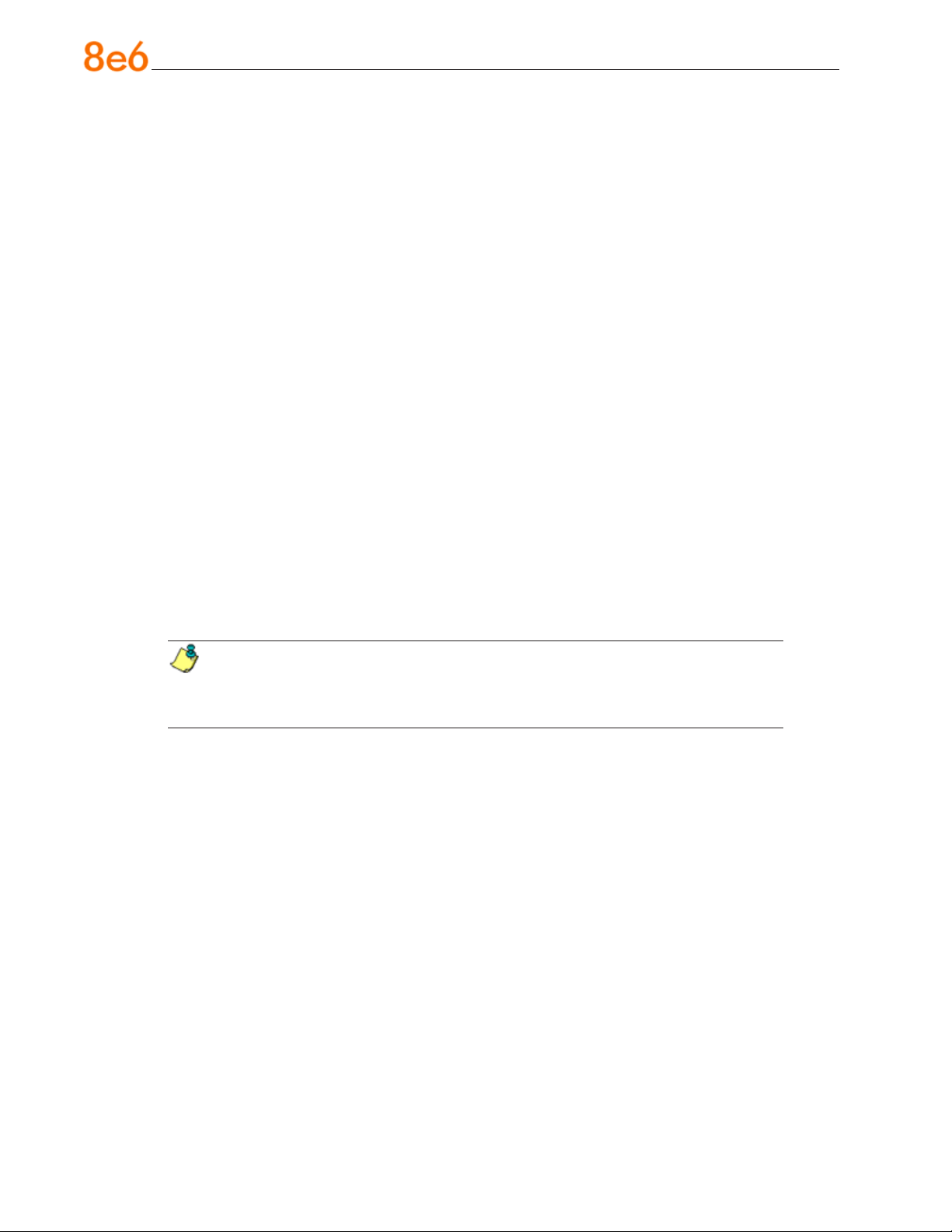
Identify the Sections of the Rack Rails
You should have received two rack rail assemblies with the 8e6 server unit. Each of
these assemblies consists of two sections: An inner xed chassis rail that secures to the
unit (A), and an outer xed rack rail that secures directly to the rack itself (B). A sliding
rail guide sandwiched between the two should remain attached to the xed rack rail. The
A and B rails must be detached from each other in order to install.
To remove the xed chassis rail (A), pull it out as far as possible. You should hear a
“click” sound as a locking tab emerges from inside the rail assembly and locks the inner
rail. Then depress the locking tab to pull the inner rail completely out. Do this for both the
left and right side rack rail.
Install the Chassis Rails
Position the xed chassis rail sections you just removed along the side of the server
chassis making sure the ve screw holes line up. Note that these two rails are left/right
specic. Screw the rail securely to the side of the chassis. Repeat this procedure for the
other rail on the other side of the chassis. You will also need to attach the rail brackets
when installing into a Telco rack.
Locking Tabs: As you have seen, both chassis rails have a locking tab, which serves
two functions. The rst is to lock the server into place when installed and pushed fully
into the rack, which is its normal position. Secondly, these tabs also lock the server in
place when fully extended from the rack. This prevents the server from coming completely out of the rack when you pull it out for servicing.
8e6 ThreaT analysis reporTer Quick sTarT Guide 5
Page 10
Install the Rack Rails
Determine where you want to place the server unit in the rack. Position the xed rack
rail/sliding rail guide assemblies at the desired location in the rack, keeping the sliding
rail guide facing the inside of the rack. Screw the assembly securely to the rack using
the brackets provided. Attach the other assembly to the other side of the rack, making
sure that both are at the exact same height and with the rail guides facing inward.
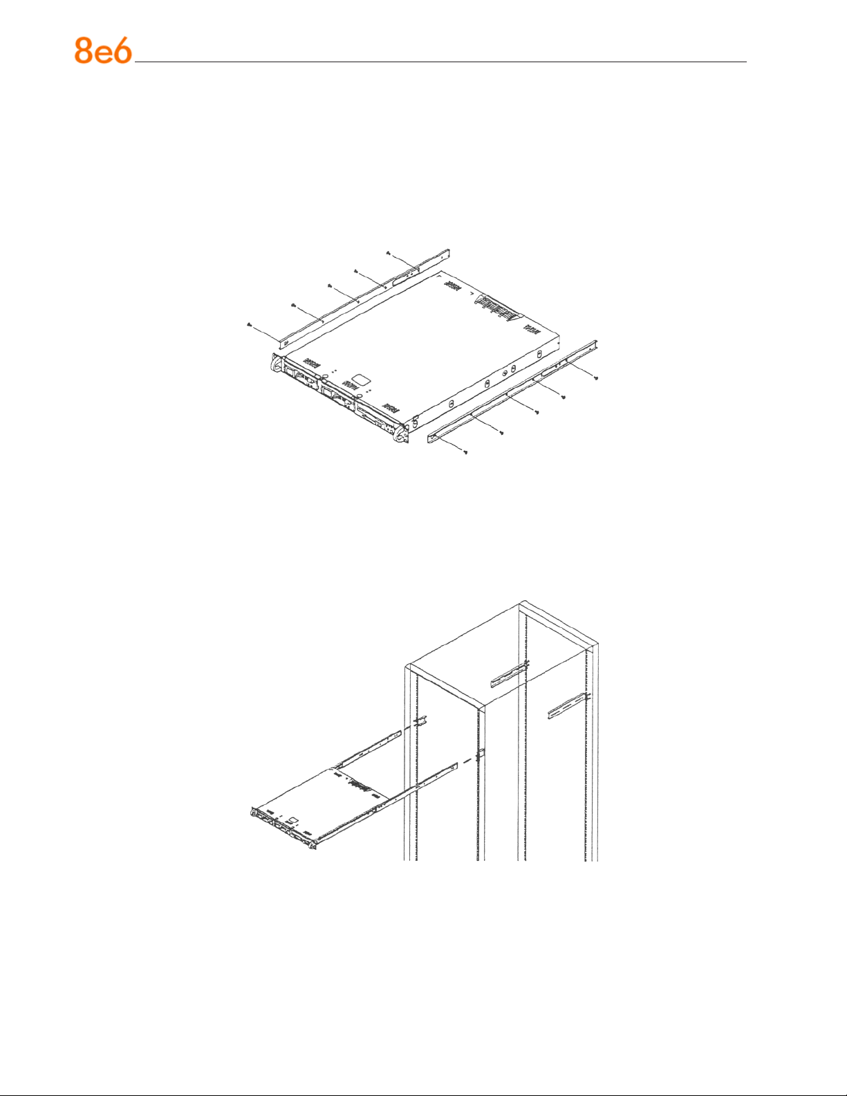
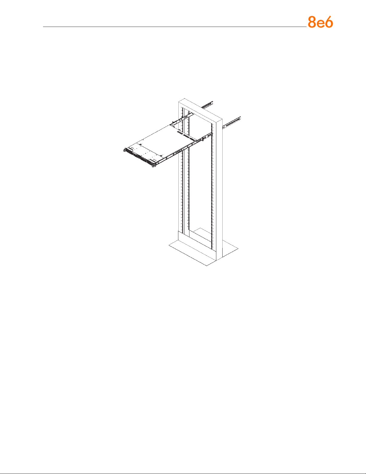
Install the Server into the Rack
You should now have rails attached to both the chassis and the rack unit. The next step
is to install the server chassis into the rack. Do this by lining up the rear of the chassis
rails with the front of the rack rails. Slide the chassis rails into the rack rails, keeping the
pressure even on both sides (you may have to depress the locking tabs when inserting).
6 8e6 ThreaT analysis reporTer Quick sTarT Guide
Page 11
Installing the Server into a Telco Rack
If you are installing the 8e6 server unit into a Telco type rack, follow the directions given
on the previous pages for rack installation. The only difference in the installation procedure will be the positioning of the rack brackets to the rack. They should be spaced
apart just enough to accommodate the width of the Telco rack.
8e6 ThreaT analysis reporTer Quick sTarT Guide 7
Page 12
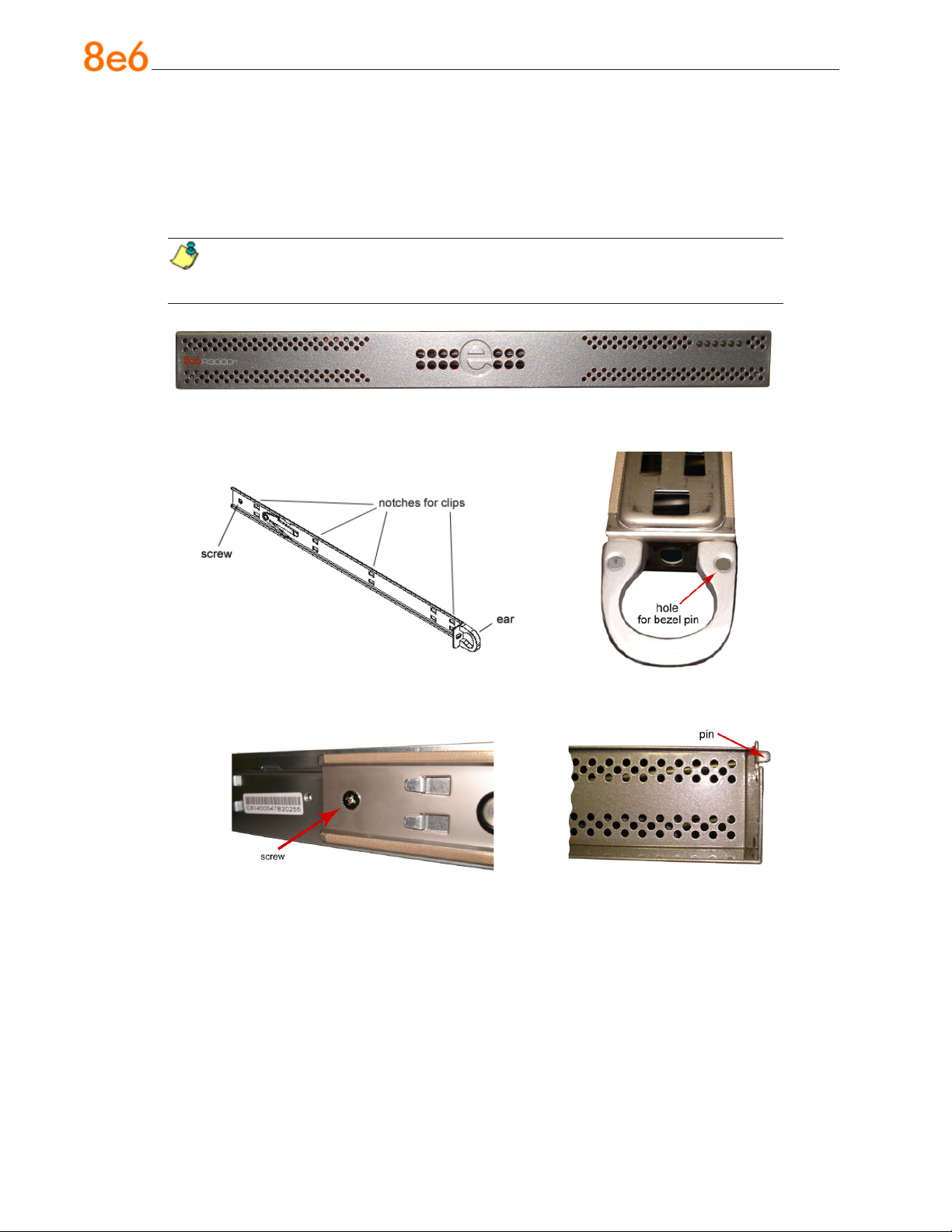
Install the “H” Server Bezel
Before rack mounting the “H” unit, the bezel should be installed on the front end of the
chassis. This portion of the installation process requires you to unpack the unit and bezel.
NOTE: The bezel has been packaged separately from the unit to prevent damage during shipping.
Front of bezel
Outside of left inner rail Inside front end of left inner
rail
Inner left rail attached to chassis Pin on right side of bezel
8 8e6 ThreaT analysis reporTer Quick sTarT Guide
Page 13
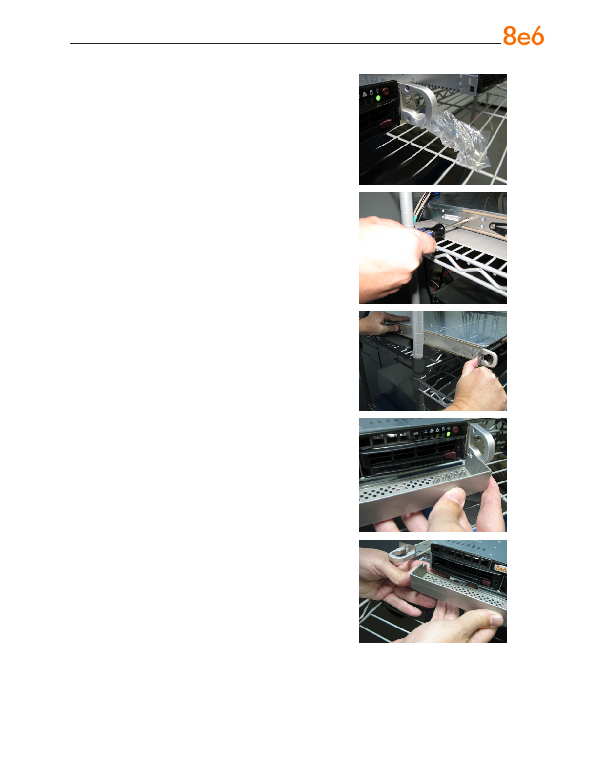
A. Remove the plastic wrapping from the left and
right ears.
B. On one side of the chassis (left or right), un-
screw the inner rail from the chassis.
C. Slide the loosened inner rail slightly backwards
to release it from the clips at the side of the
chassis, and then lay it down beside the chas-
sis, with the inside of the rail facing up.
D. On the inner rail that is still attached to the
chassis, insert the bezel pin into the bottom
hole of the ear. Be sure the pin is pushed all
the way in so that it is ush against the ear.
E. Take up the free end of the bezel and also the
loosened inner rail.
8e6 ThreaT analysis reporTer Quick sTarT Guide 9
Page 14
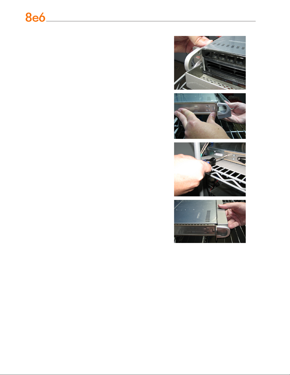
F. Return the loosened inner rail to its upright po-
sition and insert the bezel pin into the bottom
hole of the ear.
G. Slide the inner rail forward beneath the clips to
lock it in place.
H. Screw the inner rail back on the chassis.
I. After it is installed, the bezel should drop down
when it is gently tugged forward and down-
ward. The bezel should remain upright when
raised up and closed.
10 8e6 ThreaT analysis reporTer Quick sTarT Guide
Page 15

Rack Mount the “H” Server
Rack Mount Instructions
Identify the Sections of the Rack Rails
You should have received two rack rail assemblies with the 8e6 server unit. Each of
these assemblies consists of two sections: An inner xed chassis rail that secures to the
unit (A), and an outer xed rack rail that secures directly to the rack itself (B). Two pairs
of short brackets to be used on the front side of the outer rails are also included.
Install the Inner Rails
Both the left and right side inner rails have been pre-attached to the chassis. Proceed to
the next step.
Install the Outer Rails
Begin by measuring the distance from the front rail to the rear rail of the rack. Attach a
short bracket to the front side of the right outer rail and a long bracket to the rear side of
the right outer rail. Adjust both the short and long brackets to the proper distance so that
the rail can t snugly into the rack. Secure the short bracket to the front side of the outer
rail with two M4 screws and the long bracket to the rear side of the outer rail with three
M4 screws. Repeat these steps for the left outer rail.
Locking Tabs: Both chassis rails have a locking tab, which serves two functions. The
rst is to lock the server into place when installed and pushed fully into the rack, which is
its normal position. Secondly, these tabs also lock the server in place when fully extended from the rack. This prevents the server from coming completely out of the rack when
you pull it out for servicing.
8e6 ThreaT analysis reporTer Quick sTarT Guide 11
Page 16
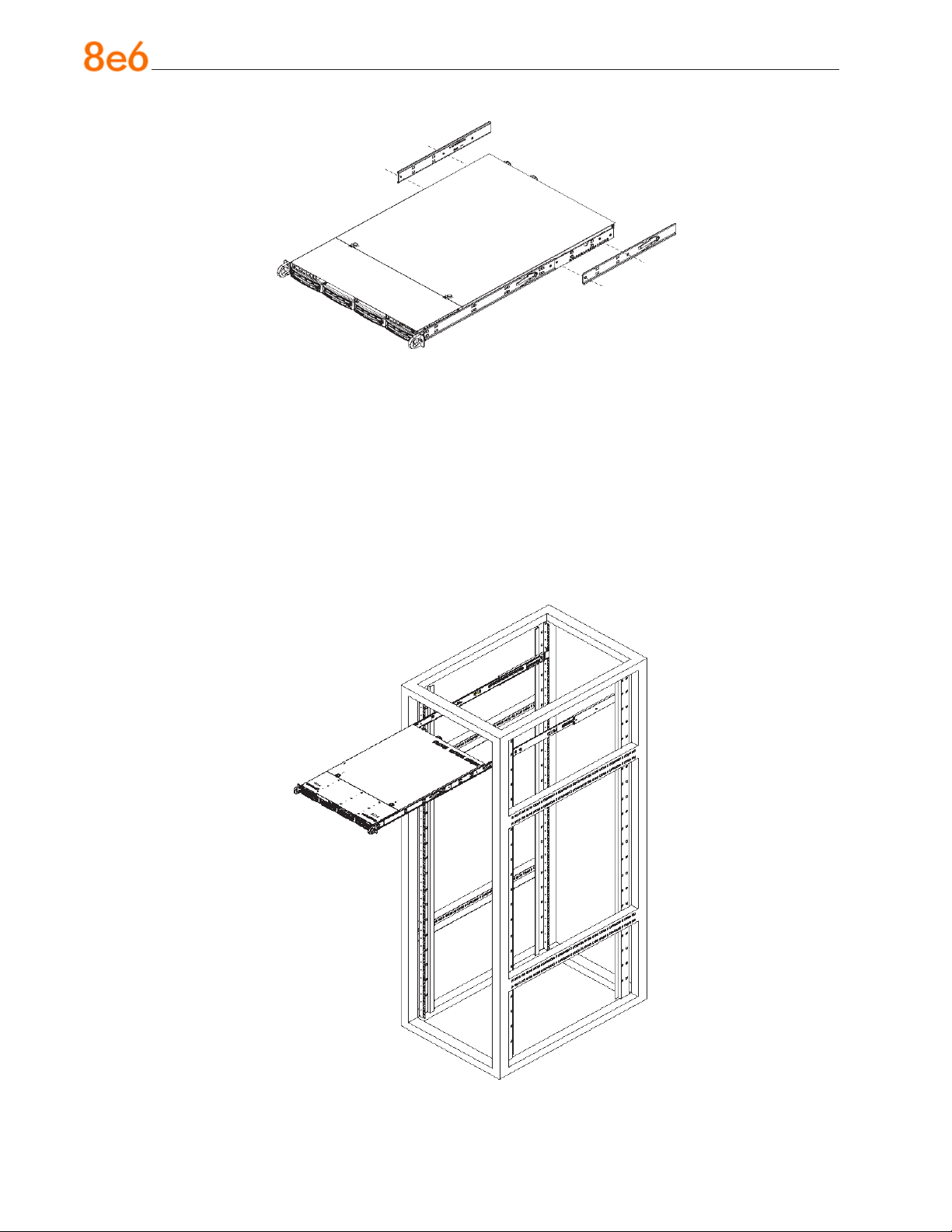
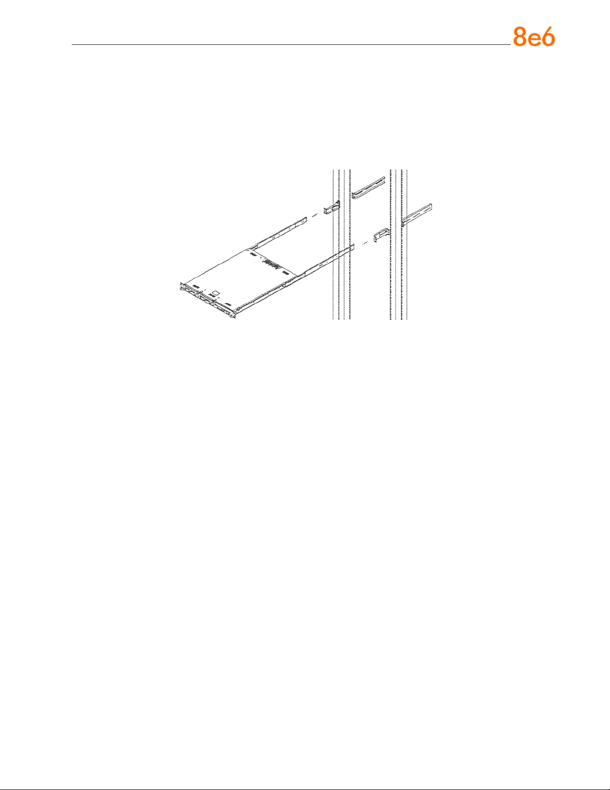
Install the Server into the Rack
You should now have rails attached to both the chassis and the rack unit. The next step
is to install the server chassis into the rack. Do this by lining up the rear of the chassis
rails with the front of the rack rails. Slide the chassis rails into the rack rails, keeping the
pressure even on both sides (you may have to depress the locking tabs when inserting).
When the server has been pushed completely into the rack, you should hear the locking
tabs “click.” Finish by inserting and tightening the thumbscrews that hold the front of the
server to the rack.
12 8e6 ThreaT analysis reporTer Quick sTarT Guide
Page 17
Installing the Server into a Telco Rack
If you are installing the 8e6 server unit into a Telco type rack, follow the directions given
on the previous page for rack installation. The only difference in the installation procedure will be the positioning of the rack brackets to the rack. They should be spaced apart
just enough to accommodate the width of the Telco rack.
8e6 ThreaT analysis reporTer Quick sTarT Guide 13
Page 18

install the server
Step 1: Initial Setup Procedures
This step requires you to link the workstation to the Threat Analysis Reporter. The following hardware can be used for the initial setup procedures:
Threat Analysis Reporter unit with AC power cord
•
either one of two options:
•
PC monitor with AC power cord and keyboard, or
•
PC laptop computer with HyperTerminal and serial port cable (and USB DB9 se-
•
rial adapter, if there is no serial port on your laptop)
NOTE: Before installing the Threat Analysis Reporter server, the R3000 server
to be used with this server must already be installed and running software version
1.10.15 or higher.
14 8e6 ThreaT analysis reporTer Quick sTarT Guide
Page 19

Link the Workstation to the Threat Analysis Reporter
Monitor and Keyboard Setup
A. Connect the PC monitor and keyboard cables to the rear of the chassis.
B. Turn on the PC monitor.
C. Power on the Threat Analysis Reporter unit by dropping down the face plate and
pressing the large button at the right of the front panel (see image below).
Front of the chassis
Once the Threat Analysis Reporter is powered up, proceed to the Step-by-Step Initial
Setup Procedures.
Serial Console Setup
A. Using the serial port cable (and USB DB9 serial adapter, if necessary), connect the
laptop to the rear of the chassis (see images below).
Rear of the “S” or “MSA” chassis
Rear of the “H” chassis
B. Power on the laptop.
C. Power on the Threat Analysis Reporter by dropping down the face plate and pressing
the large button at the right of the front panel (see top image on this page).
Once the Threat Analysis Reporter is powered up, proceed to the instructions for HyperTerminal Setup Procedures.
8e6 ThreaT analysis reporTer Quick sTarT Guide 15
Page 20

HyperTerminal Setup Procedures
If using a serial console, follow these procedures to create a HyperTerminal session.
A. Launch HyperTerminal by going to Start > Programs > Accessories > Communica-
tions > HyperTerminal:
B. In the Connection Description dialog box, enter any session Name, and then click
OK to open the Connect To dialog box:
16 8e6 ThreaT analysis reporTer Quick sTarT Guide
Page 21

C. At the Connect using eld, select the COM port assigned to the serial port on the
laptop (probably “COM1”), and then click OK to open the Properties dialog box, displaying the Port Settings tab:
D. Specify the following session settings:
Bits per second: 9600
•
Data bits: 8
•
Parity: None
•
Stop bits: 1
•
Flow control: Hardware
•
E. Click OK to connect to the HyperTerminal session:
8e6 ThreaT analysis reporTer Quick sTarT Guide 17
Page 22

F. In the HyperTerminal session window, go to File > Properties to open the Properties
dialog box, displaying the Connect To and Settings tabs:
G. Click the Settings tab, and at the Emulation menu select “VT100”.
H. Click OK to close the dialog box, and to go to the login screen.
NOTE: If using a HyperTerminal session, the login screen will display with black
text on a white background.
18 8e6 ThreaT analysis reporTer Quick sTarT Guide
Page 23

Step-by-Step Initial Setup Procedures
For these step-by-step procedures, you will need your network administrator to provide
you the LAN 1 (Ethernet 0) and LAN 2 (Ethernet 1) IP address and subnet mask, gateway IP address, DNS server IP address(es), host name of the server, and IP address for
the Web interface (if using a NAT device).
Login screen, password prompts
The login screen displays after powering on the Threat Analysis Reporter unit using a
monitor and keyboard, or after creating a HyperTerminal session.
NOTE: If the screensaver currently displays on your screen, press the Enter
key to display the login screen.
A. At the login prompt, type in menu.
B. Press the Enter key to display the Password prompt.
C. At the Password prompt, type in the following: #s3tup#r3k
D. Press Enter to display the System Conguration screen:
8e6 ThreaT analysis reporTer Quick sTarT Guide 19
Page 24

E. At the Press the number of your selection prompt, press 2 to display the Adminis-
trator Password Entry screen:
F. At the Enter the administrator password prompt, re-enter your password:
#s3tup#r3k
G. Press Enter to display the Administration menu where you can begin the step-by-
step initial setup process using the conguration screens:
H. At the Press the number of your selection prompt, press 2 to select the “Initial
Setup step-by-step” process. This process takes you to the Congure Network Interface screen.
20 8e6 ThreaT analysis reporTer Quick sTarT Guide
Page 25

Congure Network Interface screen
A. At the Enter interface LAN1 (eth0) IP address eld, enter the IP address for the
LAN 1 (Ethernet 0) interface, and then press Enter to go to the next screen.
B. At the Enter interface LAN1 (eth0) netmask eld, enter the subnet mask for the
LAN 1 (Ethernet 0) interface using the dotted decimals notation format. Press Enter
to display the conrmation prompt.
8e6 ThreaT analysis reporTer Quick sTarT Guide 21
Page 26

C. Press Y for “Yes” to conrm and save your entries for the LAN1 (eth0) interface, and
to go to the next screen.
D. At the Enter interface LAN2 (eth1) IP address eld, enter the IP address for the
LAN 2 (Ethernet 1) interface, and then press Enter to go to the next screen.
E. At the Enter interface LAN2 (eth1) netmask eld, using the dotted decimals nota-
tion format, enter the subnet mask for the LAN 2 (Ethernet 1) interface. Press Enter
to display the conrmation prompt.
F. Press Y for “Yes” to conrm and save your entries for the eth1 interface, and to go to
the Congure default gateway screen.
22 8e6 ThreaT analysis reporTer Quick sTarT Guide
Page 27

Congure default gateway screen
A. At the Enter default gateway IP eld, enter the IP address for the default gateway.
Press Enter to display the conrmation prompt.
B. Press Y for “Yes” to conrm and save your entry for the gateway IP address, and to
go to the Congure Domain Name Servers screen.
Congure Domain Name Servers screen
8e6 ThreaT analysis reporTer Quick sTarT Guide 23
Page 28

A. At the Enter rst DNS server IP eld, enter the IP address for the primary Domain
Name Server. Press Enter to go to the next screen.
B. At the Enter (optional) second DNS server IP eld, if you have a secondary Do-
main Name Server you wish to use, enter the IP address for that server. Press Enter
to display the conrmation prompt.
C. Press Y for “Yes” to conrm and save your entries for the domain name servers, and
to go to the Congure Host Name screen.
Congure Host Name screen
24 8e6 ThreaT analysis reporTer Quick sTarT Guide
Page 29

A. At the Enter host name eld, enter the host name of the server. Press Enter to dis-
play the conrmation prompt.
B. Press Y for “Yes” to conrm and save your entry for the host name, and to go to the
Time zone regional conguration screen.
Time zone regional conguration screen
A. Use the up and down arrows in your keyboard to select your region. After selecting
your locality, press Y for “Yes” to conrm and save your regional selection, and to go
to the next screen:
8e6 ThreaT analysis reporTer Quick sTarT Guide 25
Page 30

B. Use the up and down arrows in your keyboard to select your region. After selecting
your locality, press Y for “Yes” to conrm and save your regional selection, and to go
to the Congure Wizard user screen.
Congure Wizard user screen
A. At the Enter wizard user name eld, enter the username that will be used to access
the setup wizard in the Threat Analysis Reporter interface. Press Enter to display the
conrmation prompt.
B. Press Y for “Yes” to conrm and save your entry and to go to the next screen.
26 8e6 ThreaT analysis reporTer Quick sTarT Guide
Page 31

C. At the Enter wizard password eld, enter the password that will be used to access
the setup wizard in the Threat Analysis Reporter interface. Press Y for “Yes” to con-
rm and save your entry and to go to the Setup Wizard Conrmation screen.
Setup Wizard Conrmation screen
Press Y for “Yes” to save all your wizard entries and to return to the Administration
menu.
NOTE: When saving your entries, there may be a 4-10 second delay before
the Administration menu displays.
Administration menu
After making all entries using the step-by-step initial setup process, you will return to the
Administration menu. Press X to return to the System Conguration screen. Or, to verify
the status of the Threat Analysis Reporter and review the entries you made using the
wizard, press 1 to view the System Status screen.
NOTE: Changing your password using option C, “Change administration password”, will change the password for the console menu but not the Threat Analysis
Reporter console login screen.
8e6 ThreaT analysis reporTer Quick sTarT Guide 27
Page 32

System Status Screen
The System Status screen contains the following information:
LAN1 (eth0) interface for web access and R3000 communications: LAN1 (eth0)
•
IP address and netmask specied in screen 3 (Congure Network Interface), and
current status (“Active” or “Inactive”)
LAN2 (eth1) interface for bandwidth monitoring: LAN2 (eth1) IP address and
•
netmask specied in screen 4 (Congure Network Interface), and current status
(“Active” or “Inactive”)
Default gateway IP address specied in screen 5 (Congure default gateway)
•
Congure host name specied in screen 7 (Congure Host Name)
•
DNS server IP address(es) specied in screen 6 (Congure Domain Name Servers)
•
Current status of the Threat Analysis Reporter
•
Current Version of the Threat Analysis Reporter software
•
NOTE: Modications can be made at any time by returning to the specic
screen of the wizard.
Log Off, Disconnect the Peripherals
A. After completing the wizard setup procedures, return to the System Conguration
screen and press 9 to log out.
B. Disconnect the peripherals from the Threat Analysis Reporter.
28 8e6 ThreaT analysis reporTer Quick sTarT Guide
Page 33

Step 2: Physically Connect the Unit to the Network
After performing initial setup procedures for the Threat Analysis Reporter, the unit should
be physically connected to the network. This step requires a standard CAT-5E cable to
connect the unit to the network. An additional CAT-5E cable is required if the Ethernet
Tap unit will be installed for bandwidth monitoring.
A. Plug one end of a standard CAT-5E cable into the Threat Analysis Reporter’s LAN 1
port, the port on the left.
Rear of the “S” and “MSA” chassis
Rear of the “H” chassis
B. Plug the other end of the CAT-5E cable into an open port on the network switch.
Bandwidth Management
If you choose to install the Ethernet Tap for bandwidth monitoring, you will need to connect it to the Threat Analysis Reporter at this point. Refer to Appendix A at the end of this
document for instructions on how to connect the Ethernet Tap unit.
8e6 ThreaT analysis reporTer Quick sTarT Guide 29
Page 34

Step 3: Wizard Setup Procedures
For this step, you will need your network administrator to provide you the following information:
IP range and netmask of machines on the network the Threat Analysis Reporter
•
server will be monitoring
R3000 IP address, port number to be used between the R3000 and Threat Analysis
•
Reporter, and type of authentication method to be used (IP group or LDAP)
8e6 Enterprise Reporter server IP address and server name, if an ER unit is con-
•
nected to the R3000
Access the Threat Analysis Reporter Administrator Console
A. Launch Internet Explorer.
B. In the address eld, type in http://x.x.x.x:8080/8e6tar/wizard.html (in which “x.x.x.x”
represents the eth0 IP address entered in the Connect Network Interface screen
of the Step-by-Step Initial Setup Procedures). In our example, this entry would be:
http://200.100.10.10:8080/8e6tar/wizard.html.
C. Click Go to open the Threat Analysis Reporter interface and the EULA Agreement
dialog box:
30 8e6 ThreaT analysis reporTer Quick sTarT Guide
Page 35

D. After reading the End User License Agreement, you have the option to do either of
the following:
Click No to close both the EULA Agreement dialog box and the Threat Analysis
•
Reporter interface. You will not be able to enable the Threat Analysis Reporter for
use in your environment.
Click Yes to close the EULA Agreement dialog box and to open the Login dialog
•
box:
Proceed to the next sub-section: Log in to the Threat Analysis Reporter Adminis-
trator Console.
Log in to the Threat Analysis Reporter Administrator Console
A. In the Username eld of the Login dialog box, type in the username specied in the
Congure Wizard user screen of the Step-by-Step Initial Setup Procedures. In our
example, this entry would be: taruser.
B. In the Password eld, type in the password specied in the Congure Wizard user
screen of the Step-by-Step Initial Setup Procedures.
C. Click LOGIN to close the login dialog box and to go to Step 1 of wizard setup pro-
cedures in the Threat Analysis Reporter Administrator console (see Step 1: Register
administrator).
8e6 ThreaT analysis reporTer Quick sTarT Guide 31
Page 36

Step 1: Register administrator
Step 1 is performed in the left side of the rst screen of the wizard:
A. Enter the username the global administrator will use when logging into the Threat
Analysis Reporter Administrator console. The global administrator has the highest
level of permissions in the Threat Analysis Reporter interface.
B. Enter the password to be used with that username, and enter the same password
again in the conrm password eld.
C. Enter the email address of the global administrator, who will be notied via email
when gauges reach their specied upper threshold limits.
32 8e6 ThreaT analysis reporTer Quick sTarT Guide
Page 37

D. Click the [+] Add tab beow to open the IP Range Information dialog box:
E. Enter the IP address range for the bandwidth the Threat Analysis Reporter will moni-
tor.
F. Enter the Netmask for the IP range to be monitored, using the dotted decimals nota-
tion format.
G. Click OK to close the dialog box and to display your entries in the list box:
8e6 ThreaT analysis reporTer Quick sTarT Guide 33
Page 38

NOTE: Additional IP address ranges can be included by clicking the [+] Add
tab again and making the entries described in steps E through G above.
To modify an IP address range, double-click the entry in the list box to highlight it and
to display the [-] Remove tab to the left of the [+] Add tab:
To modify the entries made for the IP address range, click the [+] Add tab to re-
•
open the IP Range Information dialog box and edit information, as necessary.
Click OK to close the dialog box and to display the modied information in the list
box.
To remove the entry for the IP address range from the list box, click the [-] Re-
•
move tab. Click the [+] Add tab to open the IP Range Information dialog box and
make new entries for the IP address range.
34 8e6 ThreaT analysis reporTer Quick sTarT Guide
Page 39

Step 2: Register R3000 & ER
Step 2 is performed in the right side of the rst screen of the wizard.
R3000:
Specify information for the R3000 to be used with the Threat Analysis Reporter:
A. Click the [+] Add tab above the R3000 list box to open the R3000 Information dialog
box:
B. Enter the IP address of the R3000 server to be used with the Threat Analysis Re-
porter. In our example, this is: 200.100.160.74, which is the Ethernet 1 IP address of
the R3000 server.
C. Enter the Server Name of the R3000 to be used with the Threat Analysis Reporter,
which is any name you wish to associate with that R3000. In our example, this is:
R3000LOGO.
D. Respond to the question “Is this your Master R3000?” by clicking the “Yes” checkbox,
if this R3000 will be designated the master R3000 to be associated with the Threat
Analysis Reporter. Otherwise, leave the checkbox blank.
8e6 ThreaT analysis reporTer Quick sTarT Guide 35
Page 40

E. Click OK to close the dialog box and to display your entries in the list box:
NOTE: Additional R3000 servers can be included by clicking the [+] Add tab
again and making the entries described in steps A through E above.
To modify an R3000 entry, double-click the R3000 entry in the list box to highlight it
and to display the Set as Master tab and the [-] Remove tab to the left of the [+] Add
tab:
36 8e6 ThreaT analysis reporTer Quick sTarT Guide
Page 41

To modify the IP address and Server Name for the R3000 server, click the [+]
•
Add tab to re-open the R3000 Information dialog box, and edit information as
necessary. Click OK to close the dialog box and to display the modied information in the list box.
To designate an R3000 as the Master R3000 server, click the entry for the R3000
•
server in the list box to highlight it, and then click the Set as Master tab to display
“Master” in the Master column for that entry in the list box.
To remove the entry for the R3000 server from the list box, click the [-] Remove
•
tab.
F. Specify the User Authentication method to be used for monitoring activity on the
Threat Analysis Reporter server: “LDAP” or “IP group”:
ER:
Respond to the question “Do you have an Enterprise Reporter?” by clicking the radio
button corresponding to either “Yes” or “No”.
If “No” was selected, click NEXT > at the bottom right of the screen to go to Step 3.
•
If “Yes” was selected, the IP address and Server Name elds display in place of the
•
radio buttons. The < Back button displays above the Server Name eld.
8e6 ThreaT analysis reporTer Quick sTarT Guide 37
Page 42

NOTE: To change your answer from “Yes” to “No,” click the < Back button to
re-display the question “Do you have an Enterprise Reporter?”
A. Enter the IP address of the ER server to be used with the Threat Analysis Re-
porter. In our example, this is: 200.10.101.76.
B. Enter the Server Name of the ER server to be used with the Threat Analysis
Reporter. In our example, this is: er4logo.
C. Click NEXT > at the bottom right of the screen to go to Step 3.
NOTE: Upon clicking NEXT > the wizard will verify whether the settings made
in Step 1 and Step 2 are correct. If there is an error in any entry made, an orange
asterisk ashes beside the eld in which the error was made. Correct the error and
click NEXT > again to go to Step 3.
38 8e6 ThreaT analysis reporTer Quick sTarT Guide
Page 43

Step 3: Register Gauges
Step 3 requires you to specify settings for default gauges to be monitored by the Threat
Analysis Reporter. These gauges will display in the Threat Analysis Reporter interface
upon logging into the Administrator console.
NOTE: Return to Step 1 or Step 2 by clicking the < BACK button in the lower
left corner of this wizard screen.
Specify Gauge Groups to be Monitored
By default, all Gauges displayed in this wizard screen (Adult Content, Security, Shopping, Bandwidth, Illegal) are selected for monitoring. To deselect a gauge from the
Gauge Groups list, remove the checkmark by clicking the checkbox in the Selected
column corresponding to that gauge.
8e6 ThreaT analysis reporTer Quick sTarT Guide 39
Page 44

View, Edit Gauge Components
To view gauge components for a specied gauge, highlight and double-click the gauge
name to populate the the elds to the right of the Gauge Groups list box.
The following gauge criteria can be edited:
Name: The displayed gauge name to be used in the interface can be modied by
•
making an entry in this eld.
Lower Limit: The default amount (“0” or zero) that will represent the lower end of the
•
gauge can be adjusted to accommodate the type of activity to be monitored on your
network.
Higher Limit: The default amount (“200”) that will represent the higher end of the
•
gauge can be adjusted to accommodate the type of activity to be monitored on your
network.
Gauge Components: To remove a gauge component, go to the Selected column
•
and click the checkmark in the checkbox corresponding to the component to be
removed.
NOTE: The settings saved in this step can be modied later in the interface.
Click NEXT > at the bottom right of the screen to go to Step 4.
iv 8e6 ThreaT analysis reporTer Quick sTarT Guide
Page 45

Step 4: Server Settings
In Step 4, the following R3000 server information displays: Active Directory Settings,
SMTP Server Settings, Patch Server Settings, PROXY Server Settings, NTP Server Settings:
NOTE: Return to Step 3 by clicking the < BACK button in the lower left corner
of this wizard screen.
After reviewing the information in this screen, the following actions can now be performed:
To print this information, click the Print button.
•
To save all settings entered during the wizard process, click Save. After your infor-
•
mation is saved, the login dialog box of the Threat Analysis Reporter interface displays, and you can begin using the application.
NOTE: To shut down the Threat Analysis Reporter server, press the power
button on the front of the unit to turn off the machine.
8e6 ThreaT analysis reporTer Quick sTarT Guide 41
Page 46

ConClusion
Congratulations; you have completed the Threat Analysis Reporter quick start procedures. Now that the Threat Analysis Reporter is running on your network, the next step
is to set up user groups or administrator groups. You will set up and congure gauges
thereafter.
Obtain the latest Threat Analysis Reporter User Guide from our Web site at http://
www.8e6.com/docs/tar_ug.pdf.
iv 8e6 ThreaT analysis reporTer Quick sTarT Guide
Page 47

speCifiCations
Physical Specications
Specication “S” Value “H” Value “MSA” Value
Height 1.7” (43mm) 1.7” (43mm) 1.7” (43mm)
Width 16.8” (426mm) 17.2” (438mm) 16.8” (426mm)
Depth 22.6” (574mm) 26.8” (681mm) 14.0” (356mm)
Front clearance 2 inches (76mm) 2 inches (76mm) 2 inches (76mm)
Side clearance 1 inch (25mm) 1 inch (25mm) 1 inch (25mm)
Rear clearance 3.6 inches (92mm) 3.6 inches (92mm) 3.6 inches (92mm)
Weight 19.5 lbs (8.85 kg) 43.0 lbs (19.5 kg) 11 lbs, 5 oz (5.13 kg)
Internal Product Specications
Specication “S” Value “H” Value “MSA” Value
CPU
Memory
Hard drive capacity
Connectivity
8e6 ThreaT analysis reporTer Quick sTarT Guide 43
2.0GHz P4 CPU 2x3.6GHz Xeon CPU 2.0GHz Celeron
CPU
3GB PC4200 /
DDR2-533 Dual
Channel ECC RAM
1x250GB HDD 2x250GB HDD 1x250GB HDD
10/100/1000 10/100/1000 10/100/1000
3GB PC2700 / DDR-
333 ECC SDRAM
3GB PC2700 / DDR-
333 Dual Channel
RAM
10/100/1000
Page 48

Hardware Component Specications
Specication “S” Value “H” Value “MSA” Value
Operating temperature
range
Storage temperature range -40° C ~ +60° C (-
Operating humidity range 8 ~ 90% non-con-
Storage humidity range 5 ~ 95% non-con-
Power supply 260W AC power
Rated AC input voltage 100 ~ 240V,
Rated input frequency 50 ~ 60 Hz 50 ~ 60 Hz 50 ~ 60 Hz
Rated input current 5A MAX 10A (115V) to 5A
Rated output power 260W 560W 260W
Maximum rated BTU 1370 BTUs/Hr N/A (see specs
Nominal DC output: +3.3V 15.0A 21.0A 15.0A
Nominal DC output: +5V 25.0A 30.0A 25.0A
Nominal DC output: +12V 18.0A 42.0A 18.0A
Nominal DC output: -12V 1.0A 1.0A 1.0A
Nominal DC output: +5V
standby
Regulatory (power supply) Power Supply Safety
10° C ~ 35° C (50° F
~ 95° F)
40° F ~ 158° F)
densing
densing
supply [24-pin, (4-pin
= 12V)]
50/60Hz, 5-3 Amp
2.0A 4.0A 2.0A
/ EMC USA - UL
listed, FCC Canada
- CUL listed
Germany - TUV
Certied
Europe/CE Mark
EN 60950/IEC
60950-Compliant
10° C ~ 35° C (50°
F ~ 95° F)
-40° C ~ +60° C (40° F ~ 158° F)
8 ~ 90% non-condensing
5 ~ 95% non-condensing
560W Hot-swap
redundant AC
power supply with
PFC [ 24-pin, (8-pin
= 12V) ]
100 ~ 240V, 6050Hz, 10-5 Amp
per power supply
module (two modules included in the
chassis)
(230V)
below)
EN 60950/IEC
60950-Compliant
UL Listed (USA)
CUL Listed (Can-
ada)
TUV Certied (Germany)
10° C ~ 35° C (50° F
~ 95° F)
-40° C ~ +70° C (40° F ~ 158° F)
8 ~ 90% non-condensing
5 ~ 95% non-condensing
Thermal control
260W AC power
supply with PFC
[ 24-pin, (4-pin =
12V) ]
100 ~ 240V, 6050Hz, 5-3 Amp
5A MAX
N/A (see specs
below)
USA - UL listed,
FCC
Canada - CUL listed
Germany - TUV
Certied
Europe/CE Mark
EN 60950/IEC
60950-Compliant
iv 8e6 ThreaT analysis reporTer Quick sTarT Guide
Page 49

“S” and “MSA” Front Panel LED Indicators, Buttons
Diagrams and Descriptions
On “S” and “MSA” units, LED indicators and buttons display on the front panel to the
right:
E D C B A
F G
LED indicators alert you to the status of a feature on the unit while buttons let you perform a function on the unit.
LED Indicators and Buttons
LED Indicator Key Button Key
A. Power F. Reset
B. HDD Activity G. Power
C. LAN 1
D. LAN 2
E. Overheat
LED Indicator Color Condition Description
Power Green On System On
Off System Off
HDD Amber Blinking HDD Activity
Off No HDD Activity
LAN 1 & LAN 2 Green On Link Connected
Blinking LAN Activity
Off Disconnected
Overheat Red On System Overheated
Off System Normal
8e6 ThreaT analysis reporTer Quick sTarT Guide 45
Page 50

Tap insTallaTion
appendix: optional ethernet tap installation
This appendix pertains to the optional installation of the Ethernet Tap unit for bandwidth
monitoring.
Preliminary Setup Procedures
Unpack the Ethernet Tap Unit from the Box
Open the NetOptics Ethernet Tap box and verify that all accessories are included. Save
all packing materials in the event that the unit needs to be returned to 8e6 Technologies.
The NetOptics box should contain the following items:
1 NetOptics 10/100BaseT Tap
•
2 Power Supply units
•
2 AC Power cords
•
2 Crossover cables
•
2 Straight through cables
•
1 Installation Guide
•
Other Required Installation Items
In addition to the contents of the NetOptics box, you will need the following item to install
the Ethernet Tap unit:
1 Standard CAT-5E cable
•
Inspect the box for damage. If the contents appear damaged, le a damage claim with
the carrier immediately.
46 8e6 ThreaT analysis reporTer Quick sTarT Guide46 8e6 ThreaT analysis reporTer Quick sTarT Guide
Page 51

Install the Ethernet Tap Unit
Tap insTallaTion
Diagram showing TAR Ethernet Tap installation on the network
This step is a continuation from Step 2: Physically Connect the Unit to the Network. The
procedures outlined in this step require the use of a CAT-5E cable.
A. Provide power to the Ethernet Tap by connecting both power cords from the unit to
the power source.
AC power in rear panel of NetOptics 10/100BaseT Tap
B. If a designated master R3000 (to be used with the Threat Analysis Reporter) is al-
ready installed on the network, disconnect the cable that connects this R3000 to the
switch.
If the designated R3000 has not yet been installed, disregard this sub-step and pro-
ceed to sub-step C.
8e6 ThreaT analysis reporTer Quick sTarT Guide 47 8e6 ThreaT analysis reporTer Quick sTarT Guide 47
Page 52

Tap insTallaTion
C. Using a crossover cable, connect one end to the Switch’s port congured to be the
destination port of the Port Mirror.
If adding a Threat Analysis Reporter to an existing installation, this port would be the
port that was originally occupied by the listening interface of the R3000.
D. Connect the other end of the crossover cable to the Ethernet Tap’s Network A port.
Ports in front panel of NetOptics 10/100BaseT Tap
E. Using a straight through cable, connect one end to the Ethernet Tap’s Network B
port.
F. Connect the other end of the straight through cable to the R3000’s listening interface.
G. Using the second straight through cable, connect one end to the Ethernet Tap’s
Monitor A port.
H. Connect the other end of the second straight through cable to the Threat Analysis
Reporter’s listening interface.
Proceed to Step 3: Wizard Setup Procedures of the Threat Analysis Reporter installation
instructions.
48 8e6 ThreaT analysis reporTer Quick sTarT Guide48 8e6 ThreaT analysis reporTer Quick sTarT Guide
Page 53

Tap insTallaTion
8e6 ThreaT analysis reporTer Quick sTarT Guide 49 8e6 ThreaT analysis reporTer Quick sTarT Guide 49
Page 54

8e6 Corporate Headquarters (USA):
828 West Taft Avenue Orange, CA 92865-4232 • Tel: 714.282.6111 or 888.786.7999
Fax: 714.282.6116 (Sales/Technical Support) • 714.282.6117 (General Ofce)
Satellite Ofce:
8e6 Taiwan: RM B2, 13F, No. 49, Sec. 3, Minsheng E. Rd., Taipei 104, Taiwan, R.O.C.
Tel: 886-2-2501-5285 • Fax: 886-2-2501-5316
 Loading...