

8e6 ER HL-002-002, ER HL-022-002, ER SL-002-002 Quick Start Manual
Enterprise Reporter
®
QUICK START
GUIDE
Model: ER
HL-022-002, HL-002-002, SL-002-002
Release: 4.1.20 / Updated: 09.19.08

8e6 enterprise reporter Quick start Guide
© 2008 8e6 Technologies. All rights reserved.
This document may not, in whole or in part, be copied, photocopied, reproduced, translated, or reduced to any electronic medium or machine readable form without prior written consent from 8e6 Technologies.
Every effort has been made to ensure the accuracy of this document. However, 8e6 Technologies makes no war-
ranties with respect to this documentation and disclaims any implied warranties of merchantability and tness for a
particular purpose. 8e6 Technologies shall not be liable for any error or for incidental or consequential damages in
connection with the furnishing, performance, or use of this manual or the examples herein. The information in this
documentation is subject to change without notice.
The ER products have been tested and found to comply with the limits for a Class A digital device, pursuant to part 15
of the FCC Rules. These limits are designed to provide reasonable protection against harmful interference when the
equipment is operated in a commercial environment. This equipment generates, uses, and can radiate radio frequency energy and, if not installed and used in accordance with the instruction manual, may cause harmful interference
to radio communications. Operation of this equipment in a residential area is likely to cause harmful interference in
which case the user will be required to correct the interference at his own expense.
Trademarks
Other product names mentioned in this manual may be trademarks or registered trademarks of their respective companies and are the sole property of their respective manufacturers.
Part# ERul-QSG-080919
ii 8e6 enterprise reporter Quick start Guide

Contents
eR enteRpRise RepoRteR intRoduCtion ......................................................1
About this Document ....................................................................................................................2
Conventions Used in this Document ........................................................................................... 2
seRviCe infoRmation ..................................................................................3
pReliminaRy setup pRoCeduRes .................................................................4
Unpack the Unit from the Carton .................................................................................................4
Select a Site for the Server ...........................................................................................................5
Rack Mount the Server ..................................................................................................................6
Check the Power Supply .............................................................................................................15
General Safety Information .........................................................................................................16
install the seRveR ..................................................................................19
Step 1: Setup Procedures ........................................................................................................... 19
Step 1A: Quick Start Setup Procedures ....................................................................................20
Step 1B: Console Setup Procedures .........................................................................................28
Step 1C: LCD Panel Setup Procedures ..................................................................................... 37
Step 2: Change User Name and Password, Set Self-Monitoring ............................................ 43
Step 3: R3000 Conguration ......................................................................................................46
Step 4: Client Workstation Conguration ................................................................................. 47
Step 5: Launch the ER Client .....................................................................................................48
ConClusion .............................................................................................50
impoRtant infoRmation about using the eR in the evaluation mode ......... 51
Administrator Console, Expiration Screen ............................................................................... 51
ER Client, ER Server Statistics Window ....................................................................................52
led indiCatoRs and buttons ...................................................................53
SL Unit ..........................................................................................................................................53
HL Unit ......................................................................................................................................... 54
HL and SL Units ........................................................................................................................... 56
8e6 enterprise reporter Quick start Guide iii

RegulatoRy speCifiCations and disClaimeRs ............................................. 57
Declaration of the Manufacturer or Importer ............................................................................ 57
appendix: sCsi ConneCted stoRage deviCe ............................................ 60
Preliminary Setup Procedures ................................................................................................... 60
Install the Unit .............................................................................................................................. 65
Physical Components .................................................................................................................67
index .......................................................................................................70
iv 8e6 enterprise reporter Quick start Guide

eR enteRpRise RepoRteR intRoduCtion
Thank you for choosing to evaluate the 8e6 Technologies ER Enterprise Reporter.
The ER is designed to readily obtain information about end users’ Internet activity via
log les (text les containing Web access data) from a source device such as the 8e6
R3000 Enterprise Filter.
Both SL and HL server models include RAID technology for fault tolerance and high
performance.
The ER is comprised of the ER server and client application. Once the ER server is congured and log les have populated the database, an administrator can use the ER client reporting application to virtually generate an unlimited number of queries and reports
from data in the database. This data shows which end user is accessing which site, the
duration of each site visit, and the frequency of these visits, and can help administrators
identify Internet usage abusers, develop policies, and target sites to be ltered, in order
to maximize bandwidth utilization and productivity. The client gives the administrator the
ability to interrogate massive datasets through exible drill-down technology, until the
desired view is obtained, and then memorize and save the view to a user-dened report
menu for repetitive, scheduled execution and distribution.
8e6 enterprise reporter Quick start Guide 1
About this Document
This document is divided into the following sections:
Introduction - This section is comprised of an overview of the ER product and how
•
to use this document
Service Information - This section provides 8e6 Technologies contact information
•
Preliminary Setup Procedures - This section includes instructions on how to physi-
•
cally set up the ER in your network environment
Install the Server - This section explains how to congure the ER for reporting
•
Conclusion - This section indicates that the quick start steps have been completed
•
Evaluation Mode - This section gives information on using the ER in the evaluation
•
mode
LED Indicators and Buttons - This section explains how to read LED indicators
•
and use LED buttons for troubleshooting the unit
Regulatory Specications and Disclaimers - This section cites safety and emis-
•
sions compliance information for the ER models referenced in this document
Appendix - The appendix explains how to set up the optional NAS (SCSI Connect-
•
ed Storage Device or “SAN”) unit
Index - An alphabetized list of some topics included in this document
•
Conventions Used in this Document
The following icons are used throughout this document to call attention to important
information pertaining to handling, operation, and maintenance of the server; safety and
preservation of the equipment, and personal safety:
NOTE: The “note” icon is followed by additional information to be consid-
ered.
WARNING: The “warning” icon is followed by information alerting you to a
potential situation that may cause damage to property or equipment.
CAUTION: The “caution” icon is followed by information warning you that a
situation has the potential to cause bodily harm or death.
2 8e6 enterprise reporter Quick start Guide

seRviCe infoRmation
The user should not attempt any maintenance or service on the unit beyond the procedures outlined in this document.
Any initial hardware setup problem that cannot be resolved at your internal organization should be referred to an 8e6 Technologies solutions engineer or technical support
representative.
8e6 Corporate Headquarters (USA)
Local : 714.282.6111
Domestic US : 1.888.786.7999
International : +1.714.282.6111
8e6 Taiwan
Taipei Local : 2397-0300
Domestic Taiwan : 02-2397-0300
International : 886-2-2397-0300
Procedures
When calling 8e6 Technologies regarding a problem, please provide the representative
the following information:
Your contact information.
•
Serial number or original order number.
•
Description of the problem.
•
Network environment in which the unit is used.
•
State of the unit before the problem occurred.
•
Frequency and repeatability of the problem.
•
Can the product continue to operate with this problem?
•
Can you identify anything that may have caused the problem?
•
8e6 enterprise reporter Quick start Guide 3

pReliminaRy setup pRoCeduRes
Unpack the Unit from the Carton
Inspect the packaging container for evidence of mishandling during transit. If the packaging container is damaged, photograph it for reference.
Carefully unpack the unit from the carton and verify that all accessories are included.
Save all packing materials in the event that the unit needs to be returned to 8e6 Technologies.
The carton should contain the following items:
1 Enterprise Reporter (ER)
•
1 Bezel to be installed on the front of the chassis
•
1 AC Power Cord, 2 AC Power Cords for HL servers
•
Serial Port Cable
•
1 CAT-5E Crossover Cable
•
Rack Mount Brackets (2)
•
1 End User License Agreement (EULA)
•
1 envelope containing a CD-ROM with PDFs of the ER user guides. The latest ver-
•
sions of our user guides can be obtained at http://www.8e6.com/docs/er4server.
pdf (administrator), http://www.8e6.com/docs/er4_wclient.pdf (Web client).
NOTES: A coupler is included in the carton if a three-foot CAT-5E crossover
cable is packaged with your unit instead of a 14-foot CAT-5E crossover cable. An
additional ve-foot CAT-5E crossover cable also is included in the carton if you
have purchased the optional NAS (SCSI Connected Storage Device or “SAN”) unit.
For HL and SL servers, 1 bezel to be installed on the front of the chassis also is
included, as well as 1 spare parts kit. For HL servers, this kit contains a hard drive
and power supply. For SL servers, this kit contains a hard drive.
Inspect the server and accessories for damage. If the contents appear damaged, le a
damage claim with the carrier immediately.
WARNING: To avoid danger of suffocation, do not leave plastic bags used for
packaging the server or any of its components in places where children or infants
may play with them.
4 8e6 enterprise reporter Quick start Guide

Select a Site for the Server
The server operates reliably within normal ofce environmental limits. Select a site that
meets the following criteria:
Clean and relatively free of excess dust.
•
Well-ventilated and away from sources of heat, with the ventilating openings on the
•
server kept free of obstructions.
Away from sources of vibration or physical shock.
•
Isolated from strong electromagnetic elds and noise caused by electrical devices
•
such as elevators, copy machines, air conditioners, large fans, large electric motors,
radio and TV transmitters, and high-frequency security devices.
Access space provided so the server power cord can be unplugged from the power
•
supply or the wall outlet—this is the only way to remove the AC power cord from the
server.
Clearance provided for cooling and airow: Approximately 30 inches (76.2 cm) in the
•
back and 25 inches (63.5 cm) in the front.
Located near a properly earthed, grounded, power outlet.
•
8e6 enterprise reporter Quick start Guide 5
Rack Mount the Server
Rack Setup Precautions
Warning:
Before rack mounting the server, the physical environment should be set up to safely accommodate the server. Be sure that:
The weight of all units in the rack is evenly distributed. Mounting of the equipment in
•
the rack should be such that a hazardous condition is not achieved due to uneven
mechanical loading.
The rack will not tip over when the server is mounted, even when the unit is fully
•
extended from the rack.
For a single rack installation, stabilizers are attached to the rack.
•
For multiple rack installations, racks are coupled together.
•
Reliable earthing of rack-mounted equipment is maintained at all times. Particular
•
attention should be given to supply connections other than direct connections to the
branch circuit (e.g. use of power strips).
A power cord will be long enough to t into the server when properly mounted in the
•
rack and will be able to supply power to the unit.
The connection of the server to the power supply will not overload any circuits. Con-
•
sideration should be given to the connection of the equipment to the supply circuit
and the effect that overloading of the circuits might have on overcurrent protection
and supply wiring. Appropriate consideration of equipment nameplate ratings should
be used when addressing this concern.
The server is only connected to a properly rated supply circuit. Reliable earthing
•
(grounding) of rack-mounted equipment should be maintained.
The air ow through the server’s fan or vents is not restricted. Installation of the
•
equipment in a rack should be such that the amount of air ow required for safe operation of the equipment is not compromised.
The maximum operating ambient temperature does not exceed 104°F (40°C). If
•
installed in a closed or multi-unit rack assembly, the operating ambient temperature
of the rack environment may be greater than room ambient. Therefore, consideration
should be given to installing the equipment in an environment compatible with the
maximum ambient temperature (Tma) specied by the manufacturer.
WARNING: Extend only one component at a time. Extending two or more
components simultaneously may cause the rack to become unstable.
6 8e6 enterprise reporter Quick start Guide
Rack Mount Instructions for HL Servers
Rack Setup Suggestions
Determine the placement of each component in the rack before you install the rails.
•
Install the heaviest server components on the bottom of the rack rst, and then work
•
up.
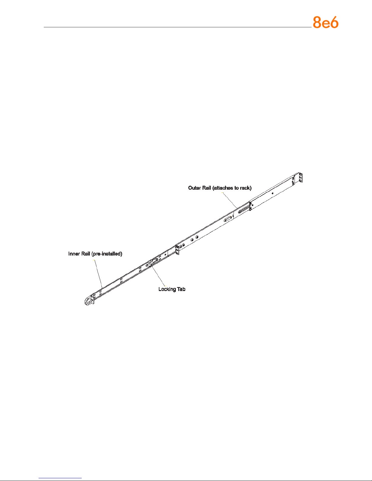
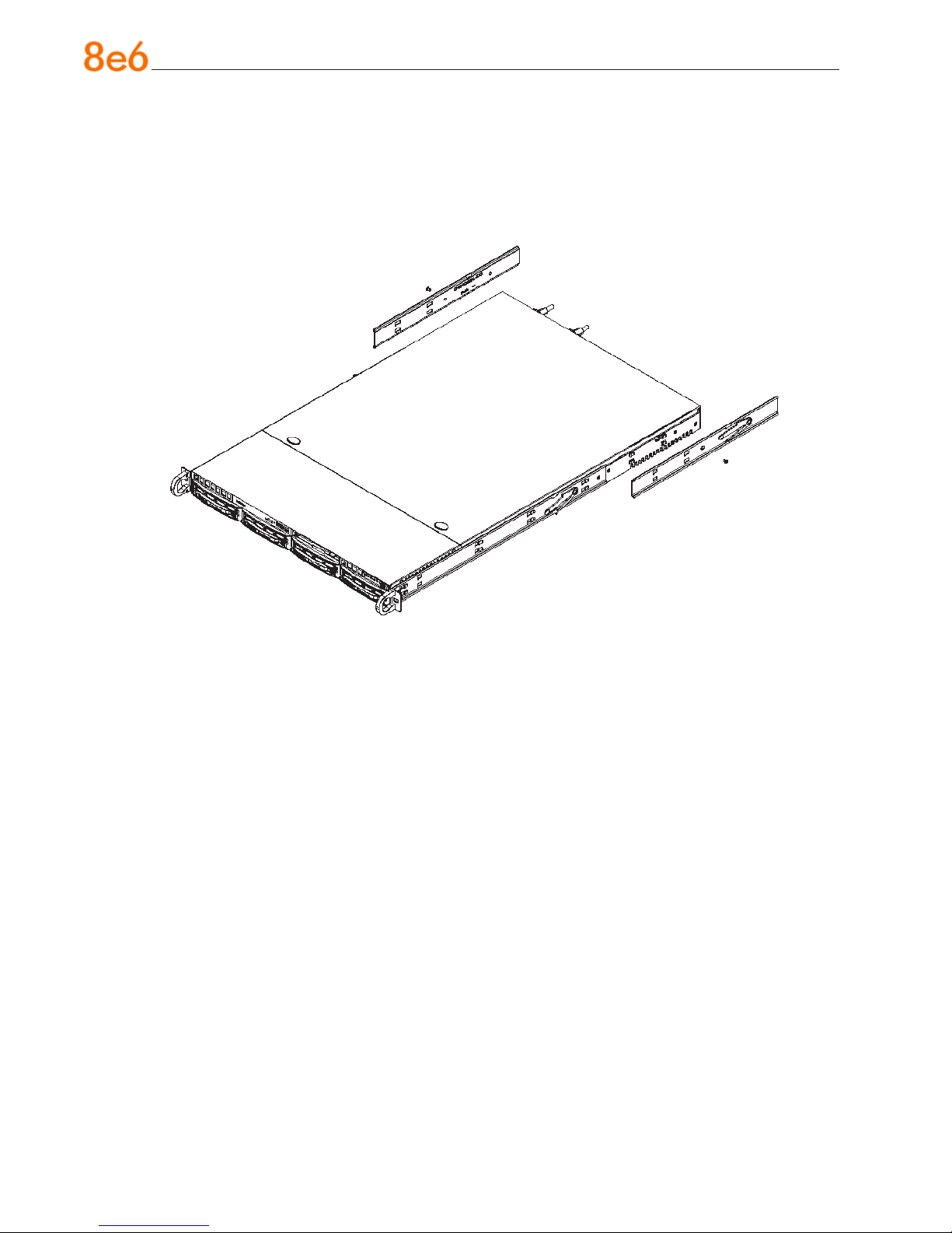
Identify the Sections of the Rack Rails
You should have received two rack rail assemblies with the 8e6 server unit. Each of
these assemblies consists of two sections: An inner xed chassis rail that secures to the
unit (A), and an outer xed rack rail that secures directly to the rack itself (B). Two pairs
of short brackets to be used on the front side of the outer rails are also included.
Install the Inner Rails
Both the left and right side inner rails have been pre-attached to the chassis. Proceed to
the next step.
Install the Outer Rails
Begin by measuring the distance from the front rail to the rear rail of the rack. Attach a
short bracket to the front side of the right outer rail and a long bracket to the rear side of
the right outer rail. Adjust both the short and long brackets to the proper distance so that
the rail can t snugly into the rack. Secure the short bracket to the front side of the outer
rail with two M4 screws and the long bracket to the rear side of the outer rail with three
M4 screws. Repeat these steps for the left outer rail.
8e6 enterprise reporter Quick start Guide 7
Locking Tabs: Both chassis rails have a locking tab, which serves two functions. The
rst is to lock the server into place when installed and pushed fully into the rack, which is
its normal position. Secondly, these tabs also lock the server in place when fully extended from the rack. This prevents the server from coming completely out of the rack when
you pull it out for servicing.
8 8e6 enterprise reporter Quick start Guide
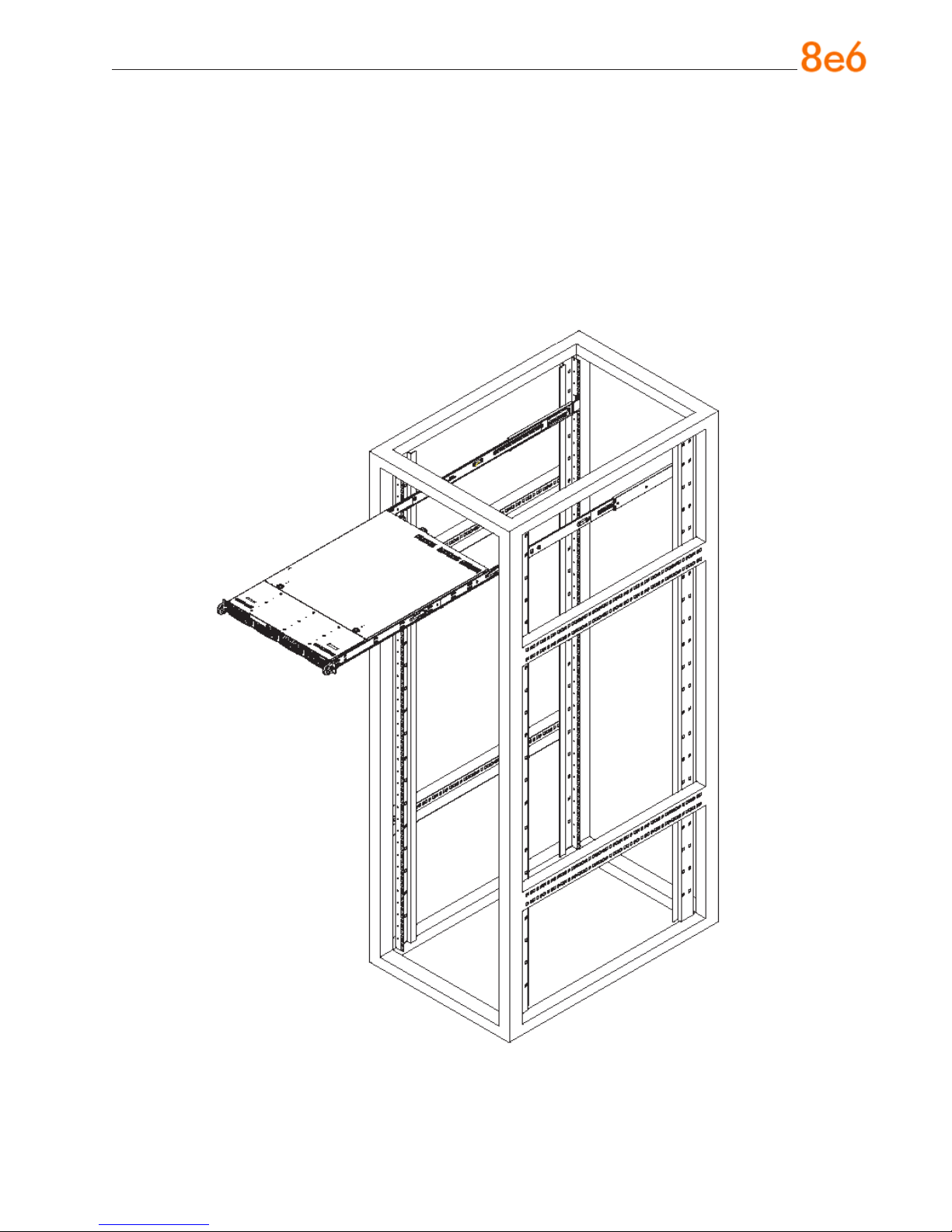
Install the Server into the Rack
You should now have rails attached to both the chassis and the rack unit. The next step
is to install the server chassis into the rack. Do this by lining up the rear of the chassis
rails with the front of the rack rails. Slide the chassis rails into the rack rails, keeping the
pressure even on both sides (you may have to depress the locking tabs when inserting).
When the server has been pushed completely into the rack, you should hear the locking
tabs “click.”
8e6 enterprise reporter Quick start Guide 9
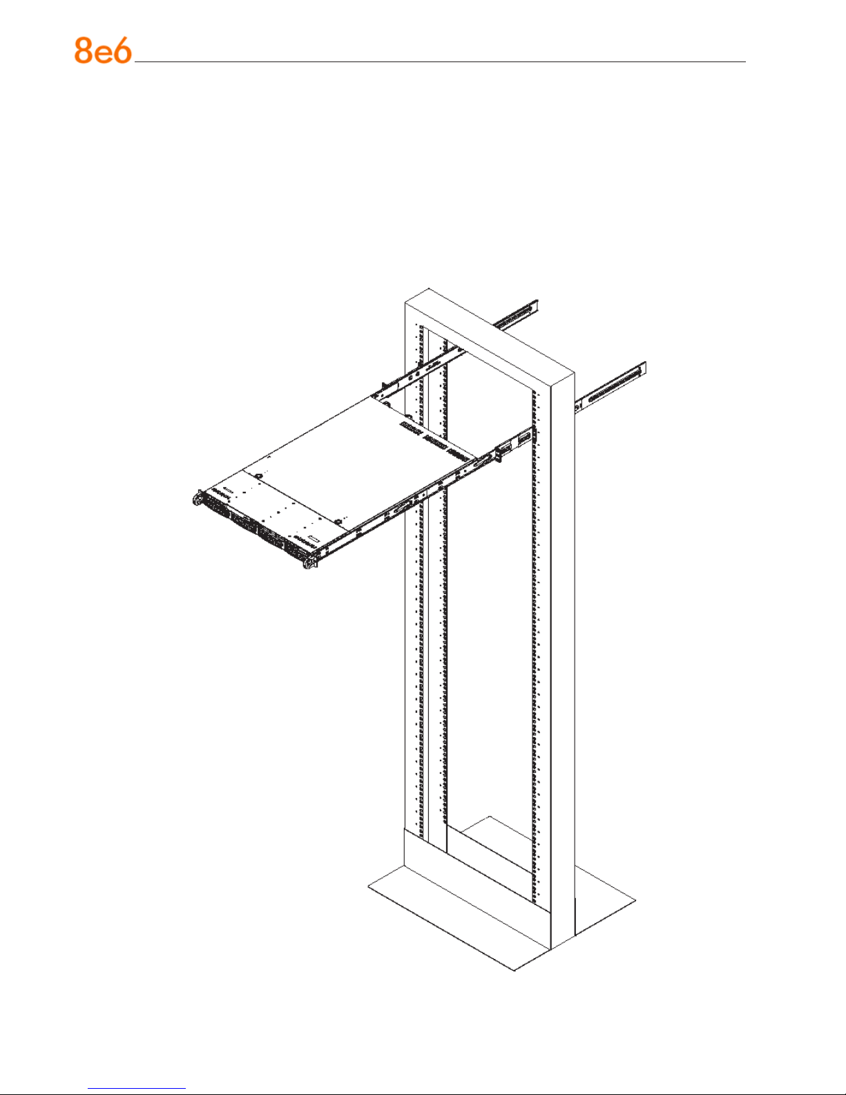
Install the Server into a Telco Rack
If you are installing the 8e6 server unit into a Telco type rack, use two L-shaped brackets
on either side of the chassis (four total). First, determine how far follow the server will extend out the front of the rack. A larger chassis should be positioned to balance the weight
between front and back. If a bezel is included on your server, remove it. Then attach
the two front brackets to each side of the chassis, then the two rear brackets positioned
with just enough space to accommodate the width of the telco rack. Finish by sliding the
chassis into the rack and tightening the brackets to the rack.
10 8e6 enterprise reporter Quick start Guide
Rack Mount Instructions for SL Servers
Rack Setup Suggestions
Determine the placement of each component in the rack before you install the rails.
•
Install the heaviest server components on the bottom of the rack rst, and then work
•
up.
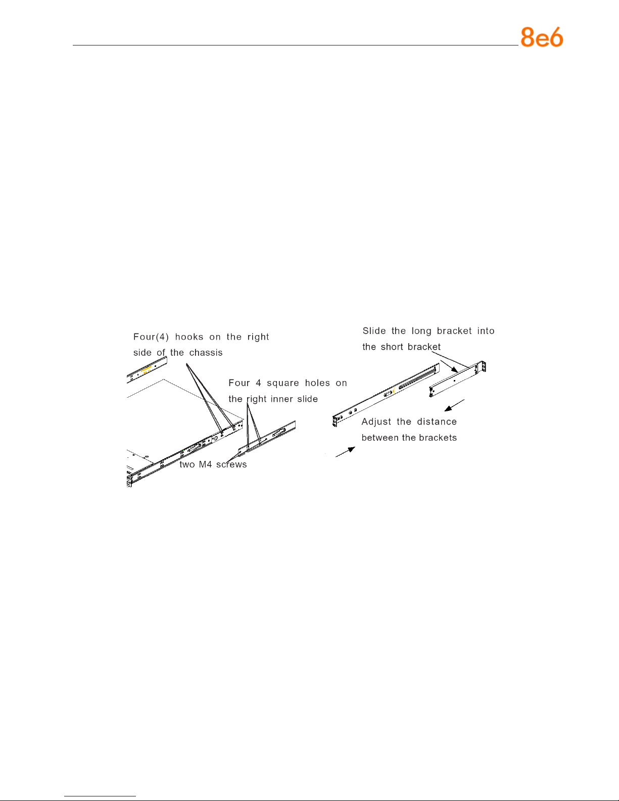
Install the Inner Slides
1. Locate the right inner slide, (the slide that will be used on the right side of chassis
when facing the front panel of the chassis).
2. Align the four (4) square holes on the right inner slide against the hooks on the right
side of the chassis as show below on the left.
3. Securely attach the slide to the chassis with two M4 at head screws and repeat the
steps 1-3 to install the left inner slide to the left side of the chassis.
Install the Outer Slides
1. Measure the distance from the front rail of the rack to the rear rail of the rack.
2. Attach a short bracket to the rear side of the right outer slide, and a long bracket to
the front side of the right outer slide as shown above on the right.
3. Adjust the short and long brackets to the proper distance so that the chassis can
snugly t into the rack.
4. Secure the slides to the cabinet with screws.
5. Repeat steps 1-4 for the left outer slide.
8e6 enterprise reporter Quick start Guide 11
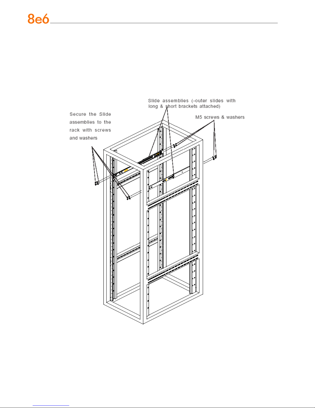
Install the Slide Assemblies to the Rack
1. After you have installed the short and long brackets to the outer slides, you are ready
to install the whole slide assemblies (outer slides with short and long brackets attached) to the rack. (See the previous page.)
2. Use M5 screws and washers to secure the slide assemblies into the rack as shown
below:
12 8e6 enterprise reporter Quick start Guide
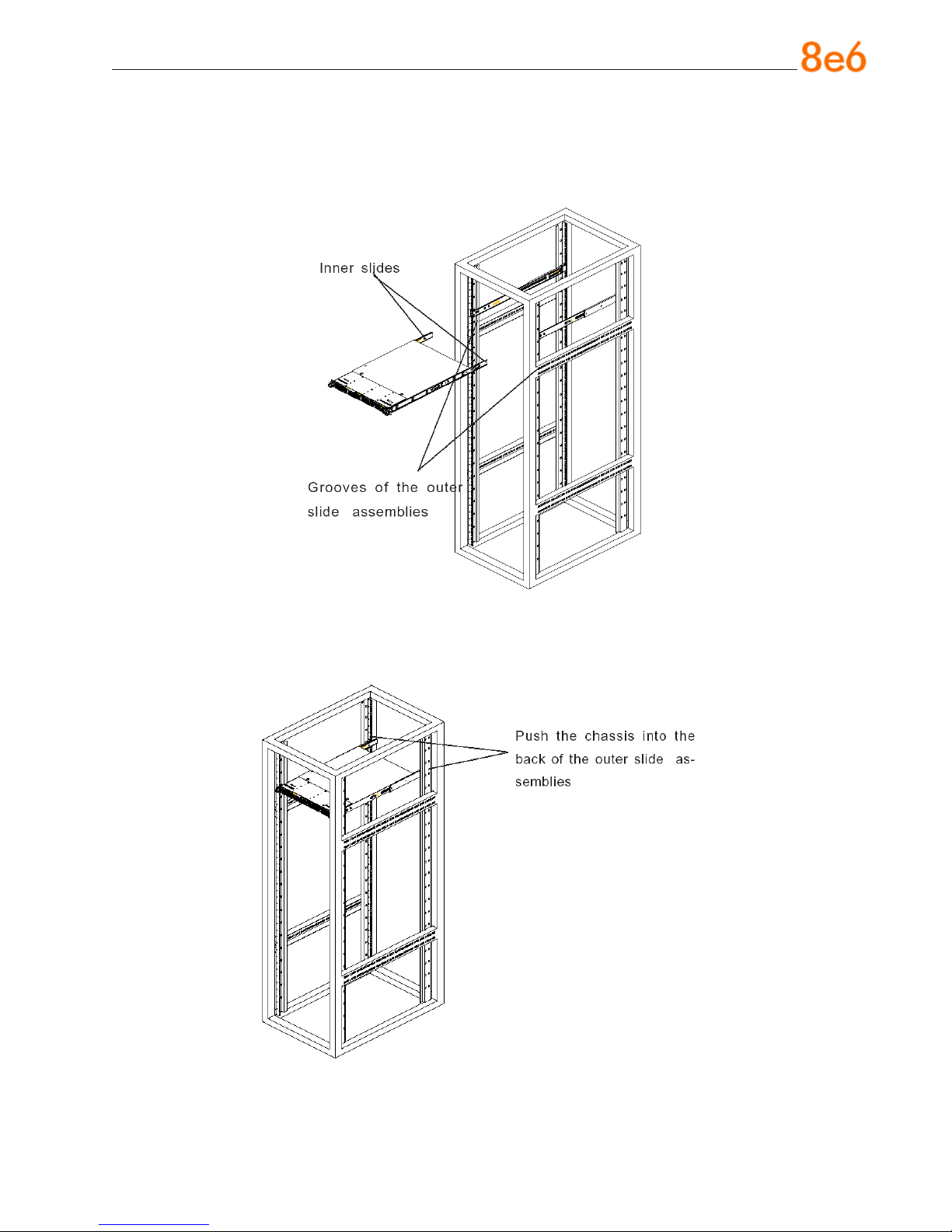
Install the Chassis into the Rack
1. Push the inner slides, which are attached to the chassis, into the grooves of the outer
slide assemblies that are installed in the rack as shown below:
2. Push the chassis all the way to the back of the outer slide assemblies as shown below:
8e6 enterprise reporter Quick start Guide 13
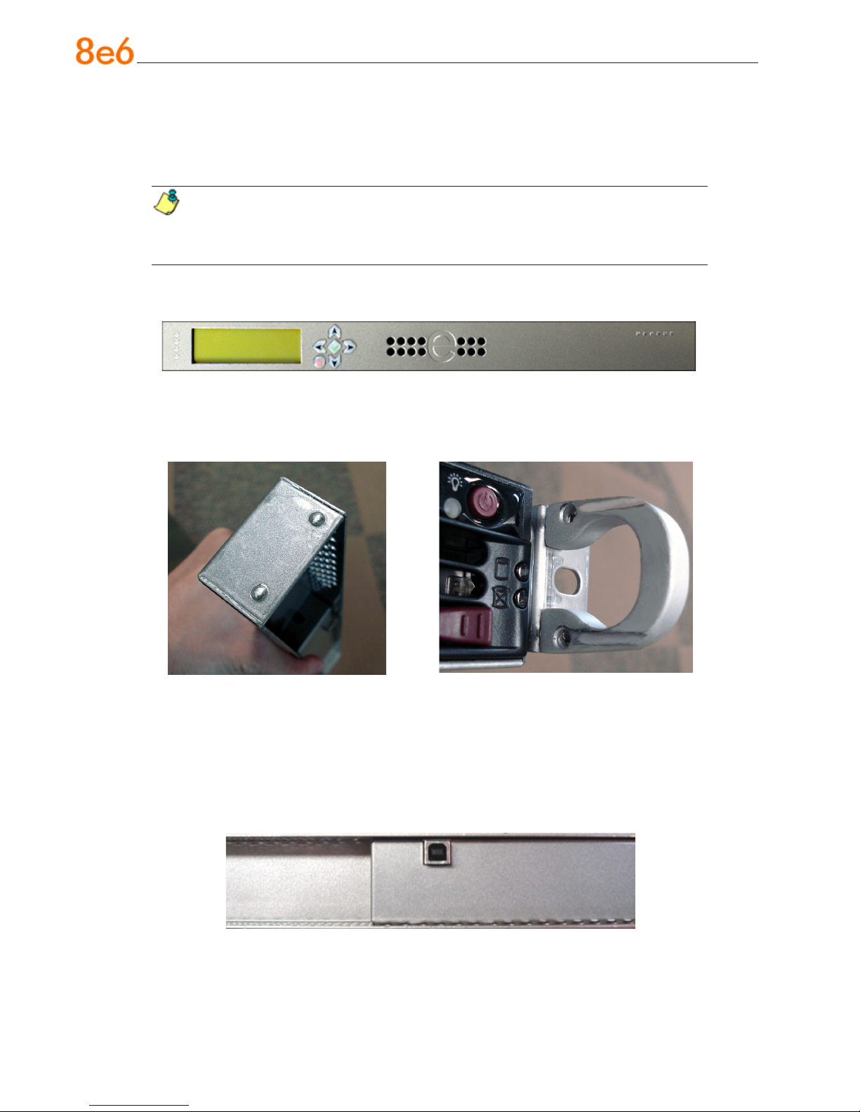
Install the SL or HL Server Bezel
After rack mounting an SL or HL server, the bezel should be installed on the front end of
the chassis.
NOTE: This portion of the installation process requires you to unpack the bezel.
The bezel has been packaged separately from the unit to prevent damage during
shipping.
A. Hold the bezel upright and facing towards you (Fig. 1).
Fig. 1 - Front of bezel
B. Note that each end of the bezel contains two raised bumps (Fig. 2).
Fig. 2 - Bumps on right end of bezel Fig. 3 - Grooves in right U-shaped handle
C. Align these bumps along the two parallel grooves inside each U-shaped aluminum
chassis handle afxed to the front end of the chassis rail (Fig. 3).
D. Push the bezel towards the front of the chassis, inserting the USB B-type plug on the
back of the bezel (Fig. 4) into the USB port on the chassis.
Fig. 4 - Section of back of bezel with USB B-type plug
14 8e6 enterprise reporter Quick start Guide
Check the Power Supply
This server is equipped with a universal power supply that handles 100-240 V, 50/60 Hz.
A standard power cord interface (IEC 950) facilitates power plugs that are suitable for
most European, North American, and Pacic Rim countries.
Power Supply Precautions
Warning:
Use a regulating uninterruptible power supply (UPS) to protect the server from power
•
surges, voltage spikes and to keep the server operating in case of a power failure.
In geographic regions that are susceptible to electrical storms, 8e6 highly recom-
•
mends plugging the AC power cord for the server into a surge suppressor.
Use appropriately rated extension cords or power strips only.
•
Allow power supply units to cool before touching them.
•
8e6 enterprise reporter Quick start Guide 15

General Safety Information
Server Operation and Maintenance Precautions
Warning:
Observe the following safety precautions during server operation and maintenance:
WARNING: If the server is used in a manner not specied by the manufacturer,
the protection provided by the server may be impaired.
WARNING: 8e6 Technologies is not responsible for regulatory compliance
of any server that has been modied. Altering the server’s enclosure in any way
other than the installation operations specied in this document may invalidate the
server’s safety certications.
CAUTION: Never pile books, papers, or other objects on the chassis, drop it,
or subject it to pressure in any other way. The internal circuits can be damaged,
and the battery may be crushed or punctured. Besides irreparable damage to the
unit, the result could be dangerous heat and even re.
CAUTION: There are no user-serviceable components inside the chassis. The
chassis should only be opened by qualied service personnel. Never disassemble,
tamper with, or attempt to repair the server. Doing so may cause smoke, re, electri-
cal shock, serious physical injury, or death.
WARNING: In HL servers, multiple sources of supply exist. Be sure to discon-
nect all sources before servicing.
Do not insert objects through openings in the chassis. Doing so could result in a
•
short circuit that might cause a re or an electrical shock.
Do not operate the server in an explosive atmosphere, in the presence of ammable
•
gases.
To ensure proper cooling, always operate the server with its covers in place. Do not
•
block any openings on the chassis. Do not place the server near a heater.
Always exit the software application properly before turning off the server to ensure
•
data integrity.
16 8e6 enterprise reporter Quick start Guide
Do not expose the server to rain or use near water. If liquids of any kind should leak
•
into the chassis, power down the server, unplug it, and contact 8e6 Technologies
technical support.
Disconnect power from the server before cleaning the unit. Do not use liquid or aero-
•
sol cleaners.
AC Power Cord and Cable Precautions
Warning:
The AC power cord for the server must be plugged into a grounded, power outlet.
•
Do not modify or use a supplied AC power cord if it is not the exact type required in
•
the region where the server will be installed and used. Replace the cord with the correct type.
Route the AC power cord and cables away from moving parts and foot trafc.
•
Do not allow anything to rest on the AC power cord and cables.
•
Never use the server if the AC power cord has been damaged.
•
Always unplug the AC power cord before removing the unit for servicing.
•
Electrical Safety Precautions
Warning:
Heed the following safety precautions to protect yourself from harm and the server from
damage:
CAUTION: Dangerous voltages associated with the 100-240 V AC power supply
are present inside the unit. To avoid injury or electrical shock, do not touch exposed
connections or components while the power is on.
To prevent damage to the server, read the information in this document for selection
•
of the proper input voltage.
Do not wear rings or wristwatches when troubleshooting electrical circuits.
•
To avoid re hazard, use only the specied fuse(s) with the correct type number, volt-
•
age, and current ratings. Only qualied service personnel should replace fuses.
Qualied service personnel should be properly grounded when servicing the unit.
•
Qualied service personnel should perform a safety check after any service is per-
•
formed.
8e6 enterprise reporter Quick start Guide 17
Motherboard Battery Precautions
Caution:
The battery on the motherboard should not be replaced without following instructions
provided by the manufacturer. Only qualied service personnel should replace batteries.
The battery contains energy and, as with all batteries, a malfunction can cause heat,
smoke, or re, release toxic materials, or cause burns. Do not disassemble, puncture,
drop, crush, bend, deform, submerge or modify the battery. Do not incinerate or expose
to heat above 140°F (60°C).
There is a danger of explosion if the battery on the motherboard is installed upside
down, which will reverse its polarities.
CAUTION: DANGER OF EXPLOSION IF BATTERY IS INCORRECTLY REPLACED.
REPLACE ONLY WITH THE SAME OR EQUIVALENT TYPE RECOMMENDED BY
THE MANUFACTURER. DISPOSE OF THE USED BATTERIES ACCORDING TO THE
MANUFACTURER’S INSTRUCTIONS.
ATTENTION: IL Y A DANGER D’EXPLOSION S’IL Y A REPLACEMENT INCORRECT
DE LA BATTERIE, REMPLACER UNIQUEMENT AVEC UNE BATTERIE DU MÊME
TYPE OU D’UN TYPE ÉQUIVALENT RECOMMANDÉ PAR LE CONSTRUCTEUR.
METTRE AU REBUT LES BATTERIES USAGÉES CONFORMÊMENT AUX INSTRUCTIONS DU FABRICANT.
WARNING: Users in Member States should consult Article 20 of Directive
2006/66/EC of the European Parliament and of the Council before disposing the
motherboard battery.
18 8e6 enterprise reporter Quick start Guide

install the seRveR
Step 1: Setup Procedures
This step requires you to link the workstation to the ER. You have the option of using the
text-based Quick Start setup procedures described in Step 1A, the Administrator console
setup procedures described in Step 1B, or the LCD panel setup procedures described in
Step 1C.
Quick Start Setup Requirements
The following hardware can be used for the Quick Start setup procedures:
ER with AC power cord
•
either one of two options:
•
PC monitor with AC power cord and keyboard, or
•
PC laptop computer with HyperTerminal and serial port cable (and USB DB9 se-
•
rial adapter, if there is no serial port on your laptop)
Go to Step 1A to execute Quick Start Setup Procedures.
Administrator Console Setup Requirements
The following hardware is required for the Administrator console setup procedures:
ER with AC power cord
•
CAT-5E crossover cable
•
PC laptop computer, or PC monitor with AC power cord and keyboard
•
Go to Step 1B to execute Console Setup Procedures.
LCD Panel Setup Requirements
The following hardware is required for LCD panel setup procedures:
ER with AC power cord(s)
•
Bezel with LCD panel mounted on chassis front
•
Go to Step 1C to execute LCD Panel Setup Procedures.
8e6 enterprise reporter Quick start Guide 19
 Loading...