

Page 1

GWS5000 Deployment Guide Version 1.0 19 July 2019 Copyright 6Harmonics Inc
GWS5000 SERIES
USER GUIDE
19th July 2019
Page 2

GWS5000 Deployment Guide Version 1.0 19 July 2019 Copyright 6Harmonics
Contents
Copyright Notice .......................................................................................................................................... 5
FCC Regulatory Notice ................................................................................................................................. 6
Part 15 TV Band Device Notice ................................................................................................................. 6
Safety Notice ................................................................................................................................................ 8
Deployment Guide Summary ...................................................................................................................... 9
GWS5000 Series Product Description....................................................................................................... 10
Applications ............................................................................................................................................ 10
Key Features ............................................................................................................................................ 11
Standards and Regulatory Compliance ................................................................................................. 12
Power Specifications .............................................................................................................................. 12
Mechanical .............................................................................................................................................. 13
Environmental ......................................................................................................................................... 13
Deployment Planning for GWS5000 Radios ............................................................................................. 14
Point-to-Point Links................................................................................................................................. 15
Point-to-Multipoint Links ........................................................................................................................ 15
Coverage ................................................................................................................................................ 16
Coverage and Propagation Estimation ............................................................................................. 16
Outdoor Propagation Considerations............................................................................................... 16
Link Margin and Expected Throughput Performance ...................................................................... 17
GWS5000 Installation ................................................................................................................................ 22
Antenna Installation .............................................................................................................................. 22
GWS Radio Unit Installation: Grounding ............................................................................................... 23
GWS Radio Unit Installation: Lightning Surge Protection ................................................................... 23
GWS Radio Unit Installation: Ethernet Cable Requirements ............................................................... 23
GWS Radio Unit Installation: Ethernet Surge Protection .................................................................... 24
Base Station Installation Schematic ...................................................................................................... 25
Base Station Installation Example..................................................................................................... 26
Client Station Installation Schematic .................................................................................................... 27
Page 3

GWS5000 Deployment Guide Version 1.0 19 July 2019 Copyright 6Harmonics
Client Station Installation Examples ................................................................................................. 28
Power over Ethernet (POE) Units ......................................................................................................... 29
Network Configuration of GWS5000 Radios ............................................................................................ 30
Preparation ............................................................................................................................................. 30
Hardware ............................................................................................................................................ 30
Software .............................................................................................................................................. 31
Other .................................................................................................................................................... 31
Configuring the GWS Radios .................................................................................................................. 31
GWS Radio GUI Login.......................................................................................................................... 31
Network Configuration Parameters ................................................................................................. 32
Setting Network Configuration Parameters .................................................................................... 33
Using the Djinni Tool to Configure the GWS Radios ........................................................................ 35
Roll-back Feature ............................................................................................................................... 40
Setting up a Radio Link .......................................................................................................................... 42
Establishing a Wireless Link between Two GWS Radios .................................................................. 42
Radio Link Performance Optimization .............................................................................................. 53
Nominet Database Settings: FCC Operation ........................................................................................ 55
Device Characteristics ........................................................................................................................ 55
Location .............................................................................................................................................. 55
Database Parameters ........................................................................................................................ 56
Owner Information ............................................................................................................................ 56
Operator Information ........................................................................................................................ 56
Database Operation: Base Station .................................................................................................... 58
Database Operation: Client Station .................................................................................................. 60
Nominet Database Settings: OFCOM Operation .................................................................................. 61
Understanding MOP, GOP & SOP Values from the Nominet Database .......................................... 63
GPS Operation .................................................................................................................................... 68
Database Tab: Nominet-OFCOM Operation ..................................................................................... 70
Database Operation: Base Station .................................................................................................... 73
Database Operation: Client Station .................................................................................................. 76
Page 4

GWS5000 Deployment Guide Version 1.0 19 July 2019 Copyright 6Harmonics
GUI Details .................................................................................................................................................. 79
Monitor Tab ............................................................................................................................................ 79
Radio Status ....................................................................................................................................... 79
Map ..................................................................................................................................................... 83
Database Agent Status ...................................................................................................................... 87
Connection Status: Base Station ....................................................................................................... 87
Connection Status: Client Station ..................................................................................................... 88
About Tab ............................................................................................................................................... 89
System Tab ............................................................................................................................................. 90
Network Tab ....................................................................................................................................... 94
Tools Tab ............................................................................................................................................ 96
Features Tab ....................................................................................................................................... 99
Database Tab .................................................................................................................................... 100
Testing Radio Database Connectivity Using Internet Connection Sharing (ICS) .................................. 101
Introduction .......................................................................................................................................... 101
Set up ICS.............................................................................................................................................. 103
Configuring the Base Station .............................................................................................................. 106
Connecting a Client Station to the Base Station ................................................................................ 109
Using a MiFi Hotspot to Configure a Client Radio with a Tablet ............................................................ 112
MiFi Unit ................................................................................................................................................ 112
Configuring the MiFi ............................................................................................................................. 113
Connecting to the GWS Radio via the WiFi Access Point of the MiFi Unit ......................................... 116
Features ..................................................................................................................................................... 120
Automatic Gain Control (AGC) ......................................................................................................... 120
ATF ..................................................................................................................................................... 122
Client RTS........................................................................................................................................... 122
Security (PSK) .................................................................................................................................... 122
TDMA ................................................................................................................................................. 122
SNMP ................................................................................................................................................. 122
Link Watchdog .................................................................................................................................. 123
Page 5

GWS5000 Deployment Guide Version 1.0 19 July 2019 Copyright 6Harmonics
QOS .................................................................................................................................................... 124
VLAN .................................................................................................................................................. 124
Troubleshooting ........................................................................................................................................ 125
Other .......................................................................................................................................................... 129
Security .................................................................................................................................................. 129
Warranty ................................................................................................................................................ 129
Terms and Conditions of Sale ............................................................................................................... 129
Database Tokens ............................................................................................................................... 129
Service and Support ............................................................................................................................. 130
Training ................................................................................................................................................. 130
Appendix ................................................................................................................................................... 131
Regulatory ............................................................................................................................................. 131
Database Parameters ....................................................................................................................... 132
Regulatory Notice USA ......................................................................................................................... 133
Regulatory Notice Canada .................................................................................................................... 134
Declaration of RF Exposure Compliance for Exemption from Routine Evaluation Limits ............ 134
Technical Brief RF Exposure Limits .................................................................................................. 135
Regulatory Notice UK .......................................................................................................................... 136
Manufacturers Declaration ............................................................................................................. 136
Product Information and Operational Parameters ............................................................................. 141
Master ................................................................................................................................................ 141
Slave ................................................................................................................................................... 142
Channel Plan .......................................................................................................................................... 143
Channel Plan 0 ................................................................................................................................... 143
Channel Plan 1 ................................................................................................................................... 146
Antennas .............................................................................................................................................. 148
Glossary of Terms................................................................................................................................. 150
Page 6

GWS5000 Deployment Guide Version 1.0 19 July 2019 Copyright 6Harmonics
Revision History
Revisions
Author
Date
Status
Notes
1.0
Mike Davies
14th January 2019
Draft
Initial release for internal review
1.1
Mike Davies
15th February 2019
Draft
Changes to Nominet Database
Settings: OFCOM Operation
following database testing.
1.2
Mike Davies
7th May 2019
Draft
Changes after RED and EMC
testing to define normal
performance and operating
specifications. P21, 51 & 123.
1.3
Mike Davies
7th June 2019
Draft
Updated FCC AGL limit,
compliance standards, max
antenna gain in manufacturers
declaration for UK.
1.4
Mike Davies
9th July 2019
Draft
Added antenna and power supply
approved components for FCC
1.5
Mike Davies
16th July 2019
Added MPE Technical Brief and RF
Exposure Compliance Declaration
for Canada.
2.0
Mike Davies
First
release
Copyright Notice
This document is protected by US and International copyright laws.
Reproduction, distribution or commercial exploitation of the content without express written
permission of 6Harmonics Inc is prohibited.
© 2019 6Harmonics Inc. Author Michael Davies
ALL RIGHTS RESERVED
Page 7

6
FCC Regulatory Notice
This device complies with part 15 of the FCC Rules. Operation is subject to the following two
conditions: (1) This device may not cause harmful interference, and (2) this device must accept any
interference received, including interference that may cause undesired operation. Any changes or
modifications not expressly approved by the party responsible for compliance could void the user’s
authority to operate the equipment.
Part 15 TV Band Device Notice
This equipment has been tested and found to comply with the rules for TV bands devices, pursuant
to CFR 47 Part 15 Sub-part H of the FCC rules1. These rules are designed to provide reasonable
protection against harmful interference. This equipment generates, uses and can radiate radio
frequency energy and, if not installed and used in accordance with the instructions, may cause
harmful interference to radio communications. If this equipment does cause harmful interference to
radio or television reception, which can be determined by turning the equipment off and on, the user
is encouraged to try to correct the interference by one or more of the following measures:
• Reorient or relocate the receiving antenna.
• Increase the separation between the equipment and receiver.
• Connect the equipment into an outlet on a circuit different from that to which the receiver is
connected.
• Consult the manufacturer, dealer or an experienced technician for help.
Caution: Exposure to Radio Frequency Radiation
To comply with FCC RF exposure compliance requirements, for fixed configurations, a separation
distance of at least 75 cm must be maintained between the antenna of this device and all persons.
This device must not be co-located or operating in conjunction with any other antenna or
transmitter.
Expert Installer
To comply with FCC interference protection requirements for TV Band Devices this equipment should
only be installed by an expert installer.
1
https://docs.fcc.gov/public/attachments/FCC-15-99A1.pdf
Page 8

7
Approved Components:
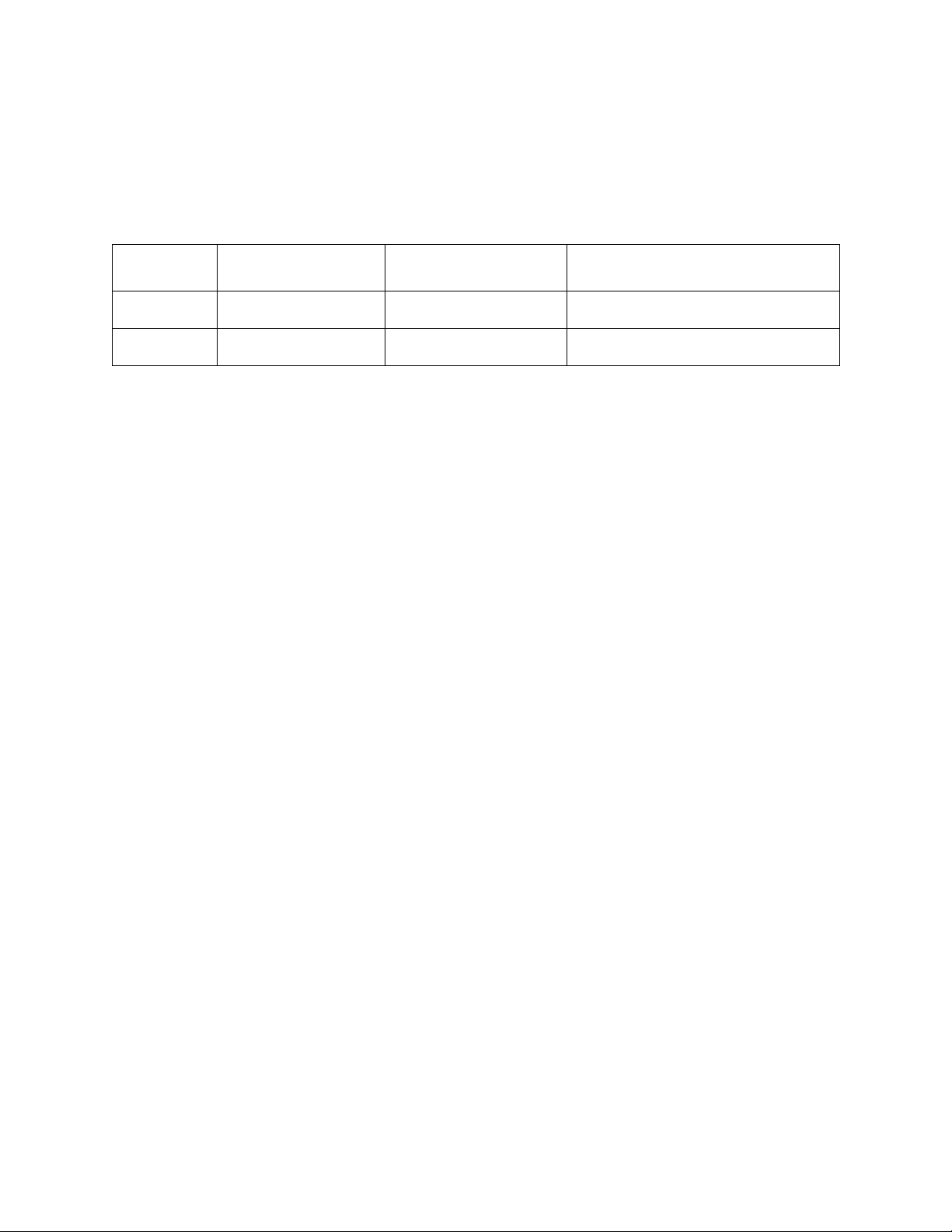
Only the following components in the table below are approved for use.
2
FCC allows the use of other power supplies to FCC certified radios as a Class 1 Permissive Change (no filing
required) under the permissive change policy ( https://apps.fcc.gov/oetcf/kdb/forms/FTSSearchResultPage.cfm?id=33013&switch=P ) so
long (i) as they are electrically equivalent and (ii) there is no degradation in emissions.
4
FCC 15.204.(c).(4) Any antenna that is of the same type and of equal or less directional gain as an antenna
that is authorized with the intentional radiator may be marketed with, and used with, that intentional radiator.
No retesting of this system configuration is required. The marketing or use of a system configuration that
employs an antenna of a different type, or that operates at a higher gain, than the antenna authorized with the
intentional radiator is not permitted unless the procedures specified in §2.1043 of this chapter are followed.
GWS
Radio
FCC
Certificate
Number
Also
approved
for:
Approved Components / Supplier
Power Supplies2
GWS-5002
GWS-5002E
Microsemi 9501 POE3
GWS-5002
GWS-5002E
Ubiquiti POE-54-80W
GWS-5002
GWS-5002E
Netonix POE switch configured to 48VH 1.5A
GWS-5002
GWS-5002E
Ubiquiti POE-50-60W
Antennas
4
GWS-5002
GWS-5002E
9dBi Dual Polarized LPDA KP Antennas PN: KP-TWDPLP9
GWS-5002
GWS-5002E
9dBi Dual Polarized LPDA Wireless Instruments PN: WiLPDA M0406-65-9X
GWS-5002
GWS-5002E
9dBi Dual Polarized LPDA Wireless Instruments PN: WiLPDA M0608-65-9X
GWS-5002
GWS-5002E
8dBi Single Polarized LPDA 6Harmonics PN: GWS-SL14174A
GWS-5002
GWS-5002E
12dBi Panel Dual Polarized Wireless Instruments SA MO4706-65-12
(Non-congested areas only)
GWS-5002
GWS-5002E
12dBi Panel Dual Polarized KP Antennas PN: KP-TWDP65S-12
(Non-congested areas only)
GWS-5002
GWS-5002E
12dBi Panel Single Polarized KP Antennas PN: KP-TWVP65S-12
(Non-congested areas only)
GWS-5002
GWS-5002E
12dBi Panel Single Polarized 6Harmonics PN: GWS-SL12948B
(Non-congested areas only)
GWS-5002
GWS-5002E
11dBi Panel Dual Polarized MTI PN: MT006D11VH
(Non-congested areas only)
GWS-5002
GWS-5002E
8dBi Panel Dual Polarized Wireless Instruments PN: WiBOX PA M0407-8X
GWS-5002
GWS-5002E
9dBi Panel Dual Polarized KP Antennas PN: KP-TWDPFP9
GWS-5002
GWS-5002E
8dBi Panel Dual Polarized Lanbowan PN: ANT0407D8Z-DP
GWS-5002
GWS-5002E
7.5dBi Panel Dual Polarized MTI PN:MT006D07VH
GWS-5002
GWS-5002E
7dBi Panel Single Polarized 6Harmonics PN: GWS-SL12948A
GWS-5002E
NA
6dBi Omni Vertical Polarization 6Harmonics PN: GWS-SL13304A
GWS-5002E
NA
2dBi Omni Vertical Polarization 6Harmonics PN: GWS-SL13319A
Page 9
8
Safety Notice
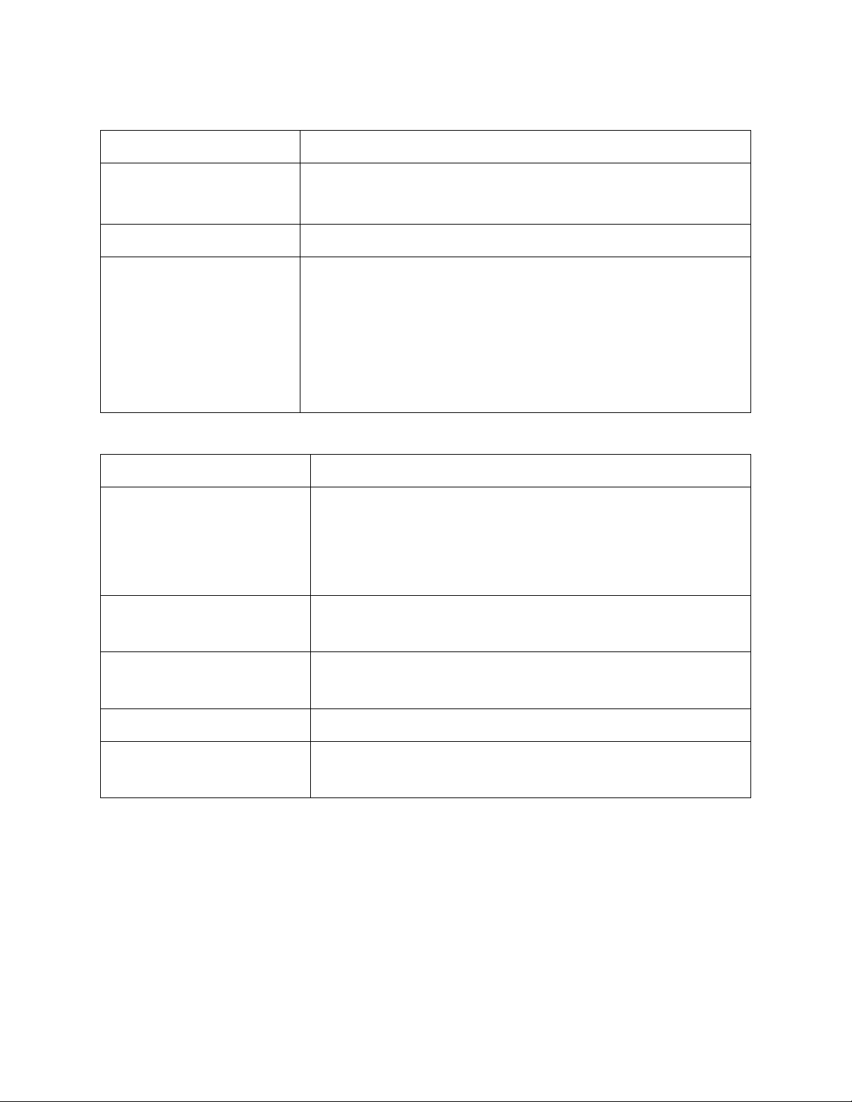
In order to avoid RF Exposure risk installers and operators must be aware of the following minimum
distances.
Mode
Max Antenna Gain
Power per RF Port
Minimum distance to avoid
exposure
MIMO
12dBi
29dBm
75cm
SISO
12dBi
29dBm
75cm
Page 10

9
Deployment Guide Summary
This deployment guide provides an overview of the 6Harmonics GWS5000 product portfolio
and how specific units can be employed to establish a wireless radio network with the
intended performance. The guide is intended to allow installers, applications engineers and
technical sales to understand all aspects of the 6Harmonics TVWS solution. This document
contains information to specify, install and set-up basic operation of a GWS series base
station with a client station for point-to-point or point-to-multipoint networks.
The guide covers:
• A description of the GWS series radio units, associated antennas and mounting hardware
• An overview of deployment considerations when using 6Harmonics products for a TV
Whitespace based wireless network. Understanding Coverage and Capacity are essential
for a successful wireless network deployment
• Installing and initiating the GWS radio units including (i) operating mode, (ii) channel
selection and (iii) establishing a reliable link between a base station and a client station
• Basic trouble shooting and best practices.
Advanced operation, such as mobility or mesh networking mode, is covered in separate
documentation and should only be performed by technicians that are trained and approved
by 6Harmonics. For advanced configuration information for GWS deployments please
contact 6Harmonics.
Page 11

10
GWS5000 Series Product Description
Best in class TV Whitespace wireless solution with industry leading throughput and range to
meet the most demanding of deployment challenges. The GWS5000 series is the most
advanced TV whitespace solution available and is the 5th generation of TV Whitespace radio
developed by 6Harmonics. Throughput with a 24MHz and a single spatial stream can achieve
72Mbps UDP and 50Mbps TCP/IP. Conducted transmit power up to 39dBm per spatial
stream (8W) is available (regulatory permitting).
Based upon the globally accepted robust WiFi protocol, the GWS5000 series radios are able
to maintain NLOS data links in the most challenging of TVWS deployments when faced with
in-band noise & interference, multipath fade, trees or other obstructions.
With a Mobility software option, the GWS5000 is unique amongst TVWS radios. Mobility
software option allows fast soft hand-over between base stations and enables mobile mesh
operation. The mobility option can be used in UK on an unlicensed basis if the CPE is
restricted to GOP mode. Mobility and MESH operation are covered in a separate document.
The SOP Direct proprietary database query process ensures that CPE can utilize SOP
operation directly without the GOP intermediate step, which enhances spectrum availability
from a TVWS database (UK only).
In the USA & Canada: the base station model number is GWS-5002 and has two transmit /
receive chains; the client station model number is GWS-5002E has a single transmit chain and
receive diversity.
In countries that require CE Mark; the base station model number is GWS-5002 and has
single transmit chain and receive diversity; the client station model number is GWS-5002 has
a single transmit chain and receive diversity.
Applications
• Rural broadband internet for residences and businesses
• NLOS backhaul to community, educational or retail WiFi hotspots
• Maritime networks
• Video surveillance & security
• Public safety communications in remote locations
• Rural IoT & Precision Agriculture
• In-building networks
Page 12

11
Key Features
• Operates on TV channels from 14 to 51 inclusive (470MHz-698MHz) in Channel Plan 0 (USA, Canada,
etc.)
• Operates on TV channels from 21 to 58 inclusive (470MHz-774MHz) in Channel Plan 1 (UK, EU, Africa,
etc.)
• Base stations: single or dual spatial stream in transmit, dual spatial stream in receive
• Client station: single spatial stream in transmit, dual spatial stream in receive
• Dual spatial stream in receive provides MIMO or receive diversity with STBC to enhance link stability
and SNR.
• LDPC forward error correction code ensures link stability even in noisy environments
• Point-to-Point, Point-to-Multipoint or Mesh
• Suitable for both access and backhaul links
• L2 connectivity enables management of residential access points directly from an edge-router behind
the base station.
• Internal GPS geolocation
• Software defined channel width from 1MHz to 32MHz, typically 6-12-18-24MHz or 8-16-24MHz.
• All stations dynamically optimize throughput based upon minimizing packet retries
• Low latentcy, typically <5mS round trip delay
• Client station scan and auto-connect
• Intuitive GUI minimizes user training and simplifies operation
• Client station beacon reading allows quick determination of base station signal strength and SSID
• Link by link throughput status including RSSI, noise, SNR, MCS, station geolocation
• Remote transmit power control of client stations from base station GUI
• Djinni tool ensures rapid login and network configuration, even if IP address lost
• Auto roll-back of IP address if not confirmed after reconfiguration, prevents loss of access
• Remote firmware upgrade via GUI
• Firmware image backup to onboard memory or save to external memory
• Map feature in combination with GPS geolocation simplifies visualization of actual network layout
• Spectrum noise scan enables optimal choice of operating channel
• Nominet database for USA & UK unlicensed operation
• LAN/WAN diagnosis tool to ensure internet access and database access are valid
• Radius client for network access validation
• Powered by readily available low-cost POE switches or single POE midspans, simple to integrate onto
existing hybrid networks using either 5GHz or 3.5GHz radios
• DC powered options available
• IP67 enclosure operates over wide temperature range and withstands moisture and precipitation
• Custom enclosures available
• Depending on the deployment scenario, links in excess of 20km can be established
Page 13
12
Standards and Regulatory Compliance
Canada
RS-222; RSS-GEN
Europe
EN 301 598 V1.1.1, EN 301 598 V2.1.1(partial);
EN 301.489-1
USA
FCC CFR 47 Part 15 Sub-part H
CE Mark
• Electromagnetic Compatibility Directive
(2014/30/EU)
• Radio Equipment Directive 2014/53/EU
• Restriction of Hazardous Substances in Electrical
and Electronic Equipment (RoHS)
• General Product Safety Directive 2001/95/EC
Power Specifications
Power supply
50-56V Passive POE++ 1/2, 4/5 (+); 3/6, 7/8 (-)
Power consumption
33dBm maximum transmit power: 35W boot, 30W
on transmit, 15W receive.
Average power consumption 25W, traffic pattern
dependent.
Recommended power
supplies
CPE: Ubiquiti POE-50-60W
BTS: Ubiquiti POE-54-80W or Netonix POE switch
configured to 48VH 1.5A
BTS (DC): Ubiquiti EdgePower EP-54V-150W
Surge suppression
Ethernet surge suppression at both client and base
stations is required.
Other custom radio configurations may require DC power. Contact 6Harmonics for details.
Page 14
13
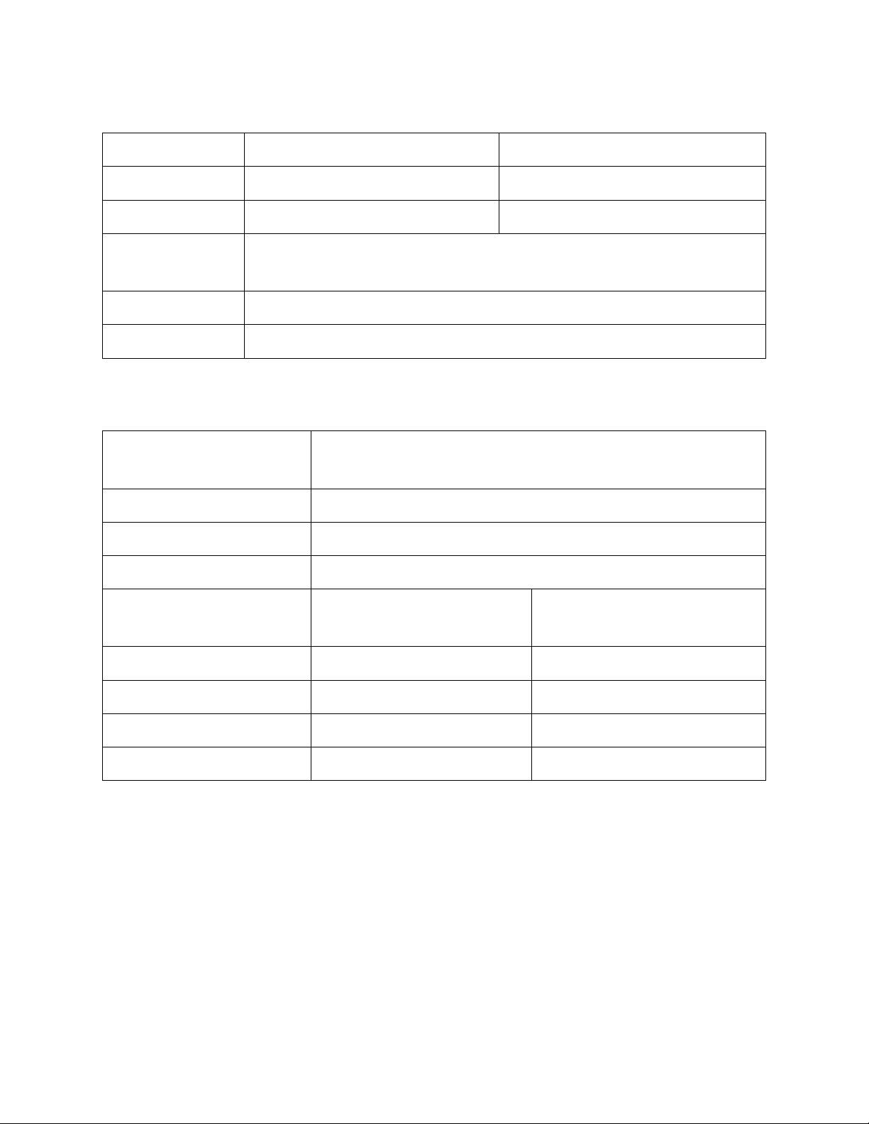
Mechanical
Dimensions
Base Station
Client Station
Weight
Housing
Mounting
1 Female RJ45 IP67 RJ45 connector. Auto-sensing 10/100-T
Ethernet.
Antenna
2 Female IP67 N-type connector
Other
Pressure equalization vent
Custom enclosures available for 8W, vehicular or maritime applications.
Environmental
Operating
Temperature
-40C to +50C (external); -40C to +85C (internal)
Storage Temperature
-50C to +90C (non-condensing)
Humidity
5%-100%
Electrostatic Discharge
15kV air, 10kV contact (power cycle may be required)
Altitude Temperature
De-rating
Altitude (m)
Temperature (C)
0 0 to +50.0
1500
0 to +47.3
3000
0 to +44.3
4500
0 to +41.1
Page 15

14
Deployment Planning for GWS5000 Radios
TV Whitespace or Super Wi-Fi are terms often used to describe wireless network solutions
that utilize VHF / UHF spectrum that has become available as TV broadcast signals have
moved from analog to digital. Because a digital TV signal uses less spectrum than an analog
TV channel these “TV Whitespaces” (TVWS) have become available for unlicensed use.
TVWS refers to unused & unlicensed blocks of frequency (channels) across the VHF and UHF
spectrum that fall between TV broadcast signals. The UHF spectrum is relatively ‘clean and
idle’ in many countries and is ideal for mobile & fixed broadband applications. Depending on
geo-location, each channel is 6-8MHz wide. Unlike unlicensed Wi-Fi spectrum, TVWS signals
propagate extraordinarily well with low loss. Non-line of sight (NLOS) penetration through
trees and around buildings is readily achievable.
From a technology perspective, key to the deployment of TVWS wireless solutions is that
the TVWS radios must be “cognitive”. This means they must; (a) know where they are
located, (b) they must know what channels are available at their location, and (c) they must
assess the channels available at their location & choose an available channel that maximizes
throughput and minimizes interference.
In USA, Canada, UK, Colombia & South Africa to ensure that a GWS radio is using a legally
available channel a GWS radio must know its longitude and latitude co-ordinates and present
these co-ordinates to an approved database for the region where the radio is deployed. This
requires that the GWS radios have access to the internet. In some regions the channel may
be set manually without access to a database (see regulatory section in Appendix).
WARNING: Any installer of GWS radios must ensure that regulatory compliance is strictly
adhered to for the region where the GWS radios are operating
Page 16
15
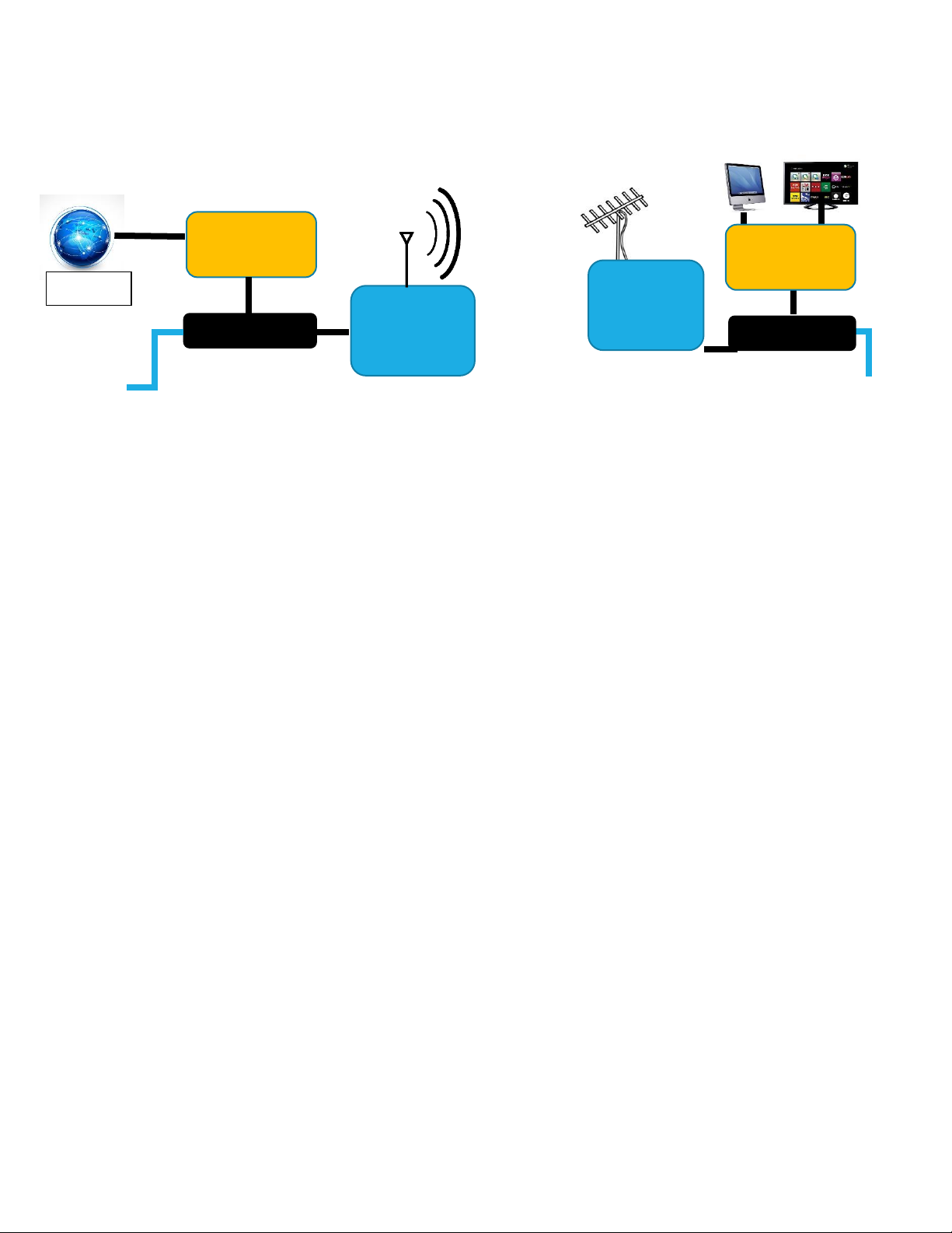
The basic deployment of a TVWS / Super Wi-Fi network using UHF is shown below:
Point-to-Point Links
In the preceding diagram if the link is between two stations only, it is a point-to-point link.
Point-to-point links are used for bridging / extending networks or as a network backhaul. In
this case we expect both to have the same configuration to ensure the link is reciprocal.
Both stations will likely have directive antennas-as the link is to connect two points only.
Directive antennas help avoid interference and maintain signal to noise ratio.
Point-to-Multipoint Links
In point-to-multipoint links a central base station is used to cover a wide area, typically with a
sectorized antenna. The client stations lying in the coverage zone then have directive
antennas pointing at the base station. Here, the client stations operate with the central base
station in a master-slave arrangement. The client stations do not connect to each other, they
only connect to the central base station.
For any deployment scenario three initial questions must be answered:
• What coverage is required?
• What capacity is required in the coverage area for the user applications at the client
stations?
• What is the RF environment?
Internet
UHF RF
AC power
GWS client
station
GWS base
station
PoE Midspan
Data network
(Router)
PoE Midspan
Router
AC power
Internet
Page 17

16
Coverage
Identify potential base station tower locations.
• Check the potential height of the antenna on the tower and the GPS co-ordinates.
• Consider the availability of TVWS spectrum from the database
• Consider the risk of noise or interference form TV or other signals.
Coverage and Propagation Estimation
There are numerous propagation models that can be used to estimate coverage5.
For a simple estimation choose:
• Transmit power: 23 dBm (0.2W conducted)
• Transmit line (co-ax) loss: 1 dB for every 5m of coax cable.
• Transmit antenna gain: 10 dBi
• Receive antenna gain: 10 dBi
• Receive line (co-ax) loss: 1dB for every 5m of coax cable.
• Receive line threshold (µV): 3µV (equivalent to noise of -98dBm)
The numbers chosen should consider regulatory restrictions for:
• Maximum antenna height above ground level. The higher the antenna, the more
expensive a tower install.
• Maximum energy in radiated power (EIRP).
Outdoor Propagation Considerations
The combined antenna gain and transmit power cannot exceed regulatory limits for a given
geolocation. Typically, a higher antenna gain has a narrower beam-which will in effect focus
the coverage area. This may, or may not, be desirable.
The model may, or may not, consider vegetation or high building coverage. These can have
significant impact on the received power. Understand what other elements are present in
the coverage area. Check Google Earth.
5
A simple and free online tool can be found at http://radiomobile.pe1mew.nl/ . This downloaded version tool
can use TVWS frequencies but a reasonable first order estimation can be performed by using the online tool
and selecting 902MHz or 450MHz as the operating frequency. Because TVWS has different propagation
characteristics than 902MHz/450MHz, the actual coverage / link budget will be different. 902MHz / 450MHz
can viewed as a min-max performance assessment for point-to point links or wide area coverage from a central
base station.
Page 18

17
Line of Sight (LOS) propagation from a client station towards a high tower may suggest that
a strong link can be established but if the link lies within the Fresnel zone problems may
occur.
Non-Line-of-Sight (NLOS) propagation is feasible at these frequencies, the RF can often have
sufficient power to penetrate buildings, woodland and propagate over hills. However, if
several steel and concrete buildings lie within the antenna sector, even high-power signals
will not be sufficient to establish a connection.
Link Margin and Expected Throughput Performance
Once an estimate of the received power coverage from a base station has been completed,
we can now estimate the link performance. In the coverage estimation we assumed an
antenna gain at the receiver.
Depending on the received signal strength at the client radio, the client radio will be able to
decode the data at varying data rates as expressed as a modulation coding scheme (MCS)
level. The higher the MCS the higher the data rate the channel can carry-known as spectrum
efficiency. This assumes a noise floor in the RF environment at the client radio receive
circuitry, typically this is -98dBm for a dual channel radio. If the received power is -88dBm
then the signal to noise ratio is 10dB.
If the receive power falls below -98dBm, received power the link will be lost. It is
unreasonable to assume that the link will be forever static. Trees grow, buildings are built,
road traffic may increase. For this reason, an additional link budget margin must be added
over the minimum target received power. 6Harmonics requires a minimum link budget fade
margin of 6dB. In other words, the design rule for received power at the client station
should be at least -72dBm to maintain MCS7.
Between -97dBm and -80dBm received power the throughput will vary as per the following
table:
Page 19

18
The GWS5000 series throughput performance:
6MHz DTT channel & SISO Operation
Connection
MCS level
Received
power (dBm)
Modulation
supported
Spectral
efficiency
(b/s/Hz)
Theoretical
PHY rate
(Mbps)
UDP
rate
(Mbps
est.)
TCP/IP
rate
(Mbps
est.)
MCS 7
>-78dBm
64 QAM 5/6
rate
56
25
16.5
12
MCS 6
-80 to 79dBm
64 QAM ¾ rate
4.5
22.5
14.7
10.9
MCS 5
-82 to -81dBm
64 QAM 2/3
rate
4
20
13.0
9.7
MCS 4
-84 to 83dBm
16 QAM ¾ rate
3
15
9.8
7.3
MCS 3
-89 to 85dBm
16 QAM ½ rate
2
10
6.5
4.8
MCS 2
-90 to 92dBm
QPSK ¾ rate
1.5
7.5
4.9
3.6
MCS 1
-93 to 95dBm
QPSK ½ rate
1 5 3.3
2.4
MCS 0
-96 to -
98dBm
BPSK ½ rate
0.5
2.5
1.6
1.2
No
connection
<-98dBm
NA
NA
NA
NA
NA
6
802.11n radios using a short guard interval of 400ns with a 20MHz channel at MCS 7 has a PHY rate of
72.2Mb/s which equates to a spectral efficiency of 3.61 b/s/Hz.
https://en.wikipedia.org/wiki/IEEE_802.11n-2009 and https://en.wikipedia.org/wiki/Spectral_efficiency
Page 20

19
24MHz DTT Channel & MIMO7 Operation
MCS
Index
Received Spatial
Streams
Modulation
Type
Coding
Rate
PHY Rate
UDP Rate
0 1 BPSK
1
2
⁄
1 1
QPSK
1
2
⁄
2 1 QPSK
3
4
⁄
3 1 16-QAM
1
2
⁄
4 1
16-QAM
3
4
⁄
5 1 64-QAM
2
3
⁄
6 1
64-QAM
3
4
⁄
7 1 64-QAM
5
6
⁄
8 2 BPSK
1
2
⁄
9 2
QPSK
1
2
⁄
10 2 QPSK
3
4
⁄
11 2 16-QAM
1
2
⁄
12 2 16-QAM
3
4
⁄
13 2 64-QAM
2
3
⁄
14 2 64-QAM
3
4
⁄
15 2 64-QAM
5
6
⁄
7
Even though the transmit may have two spatial streams the link may down grade from true MIMO to SISO
with receive diversity. The above table is a receiver perspective the transmitter could be MIMO or SISO with
transmit diversity.
Page 21

20
The previous tables are just guidelines. In reality, the “data throughput” depends on several
factors such as the application, the packet length etc etc. When deploying 6Harmonics
products, a wireless network design should include an estimate of the traffic patterns and
traffic type. Customers and installers must be aware of all aspects of their requirements to
ensure a successful deployment.
Based on the above the operator should determine:
• The ease of deployment of the base stations
• The signal levels at the proposed client stations
• The expected throughput at the proposed client stations, is it good enough for service?
MCS Level: Modulation Coding Scheme
The GWS radios use a WiFi protocol which itself uses a dynamic channel state algorithm to
set an MCS level that maximizes packet transport, specifically by minimizing the number of
packet retries needed to transport a packet over the wireless link.
If there is little traffic, the MCS level may drop, the reason is simple, only a low MCS level is
needed for minimal packet transport, so errors are minimized at a low MCS.
The links are constantly and dynamically adjusted in both uplink and downlink for all client
stations. This means a distant client with poorer SNR will receive data at a lower rate than a
client closer to the base station with a high SNR. This also means that any client with noise
or interference will not force the base station transmit to reduce the downlink transmit data
rate to that of the weakest client. All links are independently self-optimized for maximum
packet transport.
Making the Link Reciprocal
The preceding sections are focused with choosing the base station and associated antenna
to deliver sufficient EIRP to get sufficient coverage with an assumed receive sensitivity at
the client station. The link must also be designed to ensure sufficient EIRP at the client
station so that the base station has a similar receive power (RSSI) when in receive mode, as
does the client station. Generally speaking, the base station has a broader beam and higher
transmit power than the client station (more power over more area). The client station has a
lower transmit power but a more directive antenna (less power in a focused beam). In
combination this ensures the link budget between the uplink and the downlink is within 6dB.
If the uplink-downlink link budget is greater than 6dB then the link may not be able to
sustain MCS7 in both directions. If the MCS level is different in uplink and downlink then for
Page 22

21
an equivalent amount of data to be transmitted, the link with the lower MCS will require
more airtime (or access to the radio channel). The uplink and downlink will have asymmetric
throughput. If this happens poorer performing stations can degrade the overall network
throughput. This problem is mitigated by the proprietary 6Harmonics airtime fairness
algorithm, but it is preferable to ensure the link is as symmetrical as possible by considering
RF propagation, transmit power and antenna performance at the design stage.
6Harmonics recommends that before implementing a deployment an experienced wireless
networking professional be engaged by customers to ensure the RF propagation model is
realistic and the required received power and application related throughput for the target
client stations within the coverage area can be met.
Page 23

22
GWS5000 Installation
The GWS5000 radios are generally mounted on a pole or mast that shares the antenna. It is
recommended that the pole or mast be metal (galvanized steel or aluminum). When the
radio units are attached to the mast using the brackets supplied a good electrical connection
is made to the mast. Therefore, the mast or pole itself should also have a good earth as
ground for the RF. Any other radios at the same location should utilize the same ground.
If the mast/pole/bracket is not directly grounded to earth, say as a side bracket on a wall or a
roof-top tripod, then suitable conducting strapping should be employed. Typically, a ground
strap is always in place as a mitigation against lightning. If different combinations of metals
are used galvanic effects may lead to corrosion.
Plastic masts are not recommended. If plastic masts are used, separate grounds should be
used for both the antenna and the radio unit.
Antenna Installation
The antenna should be securely mounted to a pole / tower, or wall that can withstand the
wind loading associated with the surface area of the antenna at a wind speeds appropriate
to the weather conditions at the deployment location8. Certain locations may experience
high wind gusts. It is unlikely that mechanical brackets will be an issue, but the tower or pole
must be strong enough to sustain the worst expected weather conditions.
The co-axial RF cable that runs from the antenna to the GWS-radio unit should be tied to the
pole with cable ties or other suitable UV weather resistant fixtures. An installation will be
exposed to wide variations in temperature with extended UV exposure. Use good quality
materials at all times. The co-axial cable has a loss of approximately 0.5dB for a 4ft cable
with connectors. If longer cables are used the impact on the uplink-downlink link budgets
should be assessed before installation.
All co-axial connectors must be tightened but not overtightened. Problems will occur if
there are loose fittings in the RF section between the antenna and the radio. Remember
these fittings will reside outdoors for an extended period of time and will be subject to
thermal cycling daily and seasonally as well as rain, snow and ice build-up. The use of
waterproof tape is essential on all exposed connections. For USA, Canada and UK
installations a professional installer must provide the correct antenna gain and antenna
8
http://www.va3cco.com/towersheight.pdf
Page 24

23
height above ground to the radio to ensure regulatory compliance is met via the database
query.
GWS Radio Unit Installation: Grounding
When a GWS radio is installed outdoors, the enclosure must be properly grounded to allow a
discharge path in the case of a nearby lightning strike. In the event that the radio housing is
not grounded through the mounting bracket, the radio enclosure has a self-tapping screw
hole provided on the bottom of the rear facing side of the module for the attachment of a
separate ground wire. A ground wire with a Lug nut properly sized should be used to ground
to the housing. The ground wire must be at least 14 Gauge and be connected to a good
ground. If the GWS unit is mounted on a metal pole that is properly grounded this ground
wire is not required. For client station installations, it is often difficult to ground the radio
properly. In the event the radio enclosure is allowed to float, then strict attention should be
paid to the installation of ethernet surge protection (see below).
GWS Radio Unit Installation: Lightning Surge Protection
For a base station installation, a lightning suppressor (polyphaser) must installed on the coaxial cable on the GWS radio unit9. Such suppressors are not protection against a direct hit
but provide some mitigation against proximity / indirect lightning strikes. With the mast/pole
grounding approach previously described the suppressor will conduct lightning related
surges directly to ground via the mast/pole. The purpose is to protect the Tx /Rx circuitry of
the radio. A base station is typically mounted much higher AGL (above ground level) than a
client station and as such is much more at risk of lightning. A client station is typically
mounted much lower. For this reason, lightning surge suppressors are mandatory for base
stations but optional for client stations.
GWS Radio Unit Installation: Ethernet Cable Requirements
The ethernet cable running from the POE switch / POE injector should be good quality
outdoor Cat5e cable. The cable must have ground shield and be 24AWG. The outer sleeve
should be UV resistant. Good quality grounded (metal shield) RJ45 connectors should be
used. The GWS radio comes with an IP67 waterproof RJ45 connector. The waterproof gland
(5 pieces) is provided separately within the kit. The waterproof gland is designed to provide
a water tight interface for cables with an outer diameter between 5mm and 7mm. For
connections to the radio and outdoor ethernet surge suppressors the waterproof gland
9
For example: http://www.polyphaser.com/SiteMedia/SiteResources/EngineeringSpecDocuments/TUSX-
NFM.pdf
Page 25

24
must be tight and fitted properly. The connectors must be taped with good quality
waterproof tape. Care must be exercised to ensure none of the threads are crossed so the
waterproof seal is tight.
GWS Radio Unit Installation: Ethernet Surge Protection
Ethernet surge suppressors are essential to ensure protection of the data port on both the
radio and the data port of the POE unit.
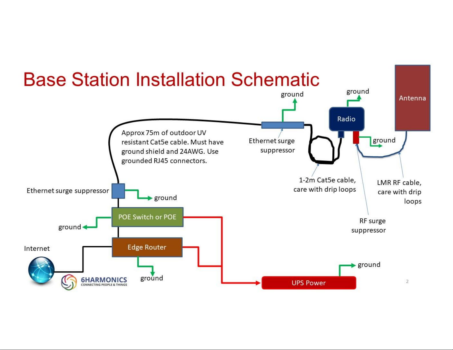
For a base station a high quality outdoor ethernet surge suppressor should be mounted
within 2m of the radio and must be properly grounded. The purpose of this surge suppressor
is to prevent spurious signals picked by the ethernet cable getting into the radio. This cable
can easily be 75m in length, and in effect can act as antenna to any RF. In addition, the POE
at the base of the tower should also have surge protection to ensure spurious signals do not
go into the switch or edge router that provides the data connection to the internet. Both
ends need protection on a base station.
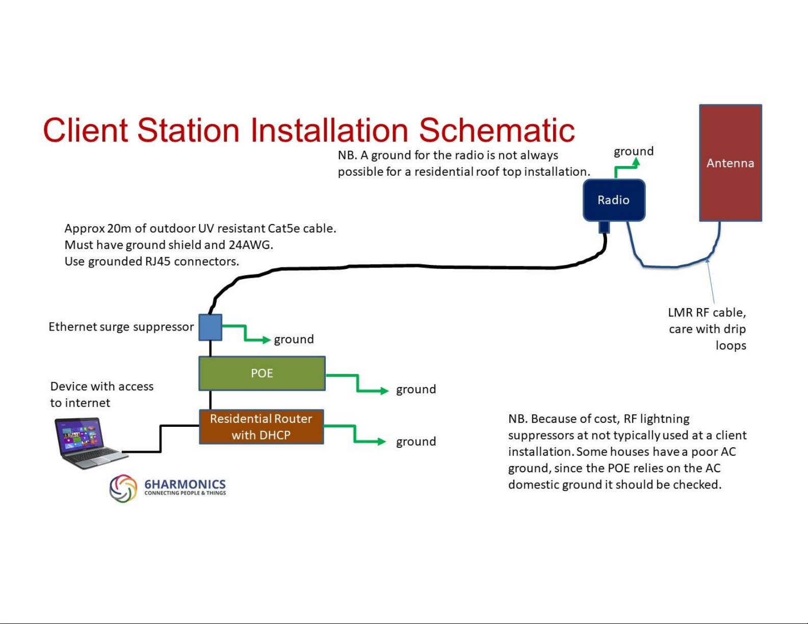
For a client station, an outdoor ethernet surge suppressor is required. This surge suppressor
maybe mounted indoors or outdoors. It must be grounded properly. Outdoors is preferred
as this allows access to the radio by a service technician without going inside the residence.
In this case the surge protector provides surge protection to the radio from the POE, and
equally provides protection to the residential router behind the client station radio POE. The
distance between the radio and the residential router is much less than in the case of the
base station, so only one surge suppressor is needed.
WARNING: In many rural locations power can be of poor quality and significant power
surges can occur when the power comes back on after a power cut. For this reason alone,
the client station installation should have a surge suppressor as described above. Installers
should also check, using a suitable GFCI tester, that the power outlet in the residence that
drives the GWS radio POE is grounded properly. Typically, in the event of a power surge a
client station will re-boot and automatically re-connect to the base station. In the event
that the radio (base station or client station) does not automatically reboot after a power
surge, remove the power cord from the POE unit, wait 1 minute. Re-insert the power cord
to the POE, and the radio should reboot within 1 minute and reconnect within 5 minutes.
This is the hard re-set procedure.
Page 26
25
Base Station Installation Schematic
Page 27
26
Base Station Installation Example
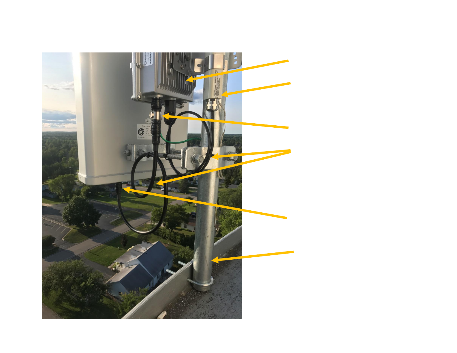
GWS radio
RF connector to antenna
Drip loops
Ethernet surge suppressor
(NB should be horizontal, and
connector taped).
RF surge suppressors
Grounded mounting pole
Page 28
27
Client Station Installation Schematic
Page 29
28
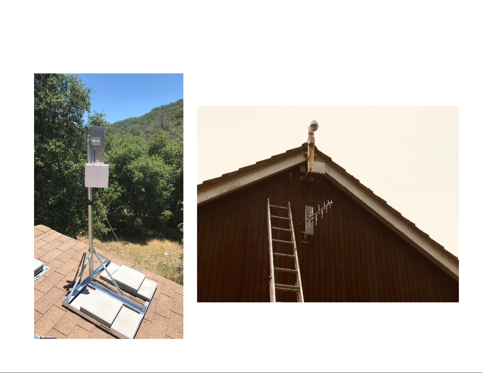
Client Station Installation Examples
Page 30

29
Power over Ethernet (POE) Units
6Harmonics has qualified the following Power-over-Ethernet (PoE) midspan units to power
the GWS radio units.
GWS Radio
POE Unit
Output
Max
Data rate
(Mbps)
Power
Notes
GWS5000 BTS
Ubiquiti POE-54-80W
54V,
1.5A
10/100/1000
80W
Use with cable
runs >30m
GWS5000 CPE
Ubiquiti POE-54-80W
54V,
1.5A
10/100/1000
80W
Use with cable
runs >30m
GWS5000 CPE
Ubiquiti POE-50-60W
50V,
1.2A
10/100/1000
60W
Use with cable runs
<30m
GWS5000 BTS
Netonix POE switch
configured to 48VH 1.5A
48V,
1.5A
10/100/1000
72W
Can be used to
power non-GWS
radios
GWS5000 BTS
Ubiquiti EdgePoint
EP-R8 / EP-S16
54V,
1.4A
10/100/1000
75W
Can be used to
power non-GWS
radios
The PoE midspans are typically located indoors to remotely power GWS radios that are
located outdoors. The GWS radios require 48-56V Passive POE++ 1/2, 4/5 (+); 3/6, 7/8 (-).
WARNING: Power is supplied over 4 pairs and as such it is critical to test any cables for
continuity before testing. A data connectivity test is insufficient. A continuity tester that
tests all pairs and the ground shield must be used.
In a base station install the length of Cat5e cable is typically much longer than in a CPE
install. In this case the POE midspan must account for the additional power losses in the
cable run. If other PoE midspan units than those listed above are used 6Harmonics reserves
the right to refuse warranty support the GWS radio units. Please contact 6Harmonics before
using any other POE midspan10.
Warning: Follow the connection procedure in the Network Configuration of GWS5000
Radios when connecting the GWS-radio unit, the PoE midspan and AC power. Do not hot
swap the RJ45 connectors on the POE midspan. To power down the radio remove the
power cord to the midspan. To power-up the radio check the midspan is not powered i.e.
power cord removed, connect the midspan to the radio and then power-up the midspan.
10
FCC allows the use of other power supplies to FCC certified radios as a Class 1 Permissive Change (no filing
required) under the permissive change policy ( https://apps.fcc.gov/oetcf/kdb/forms/FTSSearchResultPage.cfm?id=33013&switch=P ) so
long (i) as they are electrically equivalent and (ii) there is no degradation in emissions.
Page 31

30
Network Configuration of GWS5000 Radios
Preparation
Hardware
Use a Windows (version 7 or later preferred) or Linux PC, configure the ethernet adapter to
be on the same subnet as the default IP configuration of the GWS radios.
Default IP address for base station (CAR) and client station (EAR) is the same:
IP address 192.168.1.1
Network mask 255.255.255.0
Gateway 192.168.1.1
DNS 8.8.8.8
WARNING: The DNS setting default is 8.8.8.811 which is a public DNS. For most deployments
the default public DNS will be fine. However, if the GWS radios are behind firewalls or
other internet security solutions the network may need a private DNS that must be used in
order for the GWS radio to access the internet. If the GWS radio cannot make a successful
DNS query it will not be able to access the internet and, in the case of networks that
require a successful database query before the radio can turn on, the GWS radio will NOT
operate.
The ability to set a private DNS is provided to ensure the radios can always access the
database.
NOTE: a base station and a client station are not required to have the same DNS, both
radios must simply have a valid DNS.
11
An alternative public DNS to 8.8.8.8 is 8.8.4.4
Page 32

31
Software
OS: Windows 7 or later
Mac: OSx v10.10 or later
Web browser: Chrome Web Browser Version 52.0 or later
WARNING: Only Chrome is fully verified, some browsers such as Mozilla will NOT work.
TIP: If Chrome is slow to load, clear the cache.
Other
• Network with Internet access
• Ethernet cables that have been tested for continuity.
Configuring the GWS Radios
GWS Radio GUI Login
To access the configuration utility, open the Chrome web-browser and enter the default IP
address 192.168.1.1
If user is shown a warning that web certification or private network is not safe, please
proceed to the web page until login page appears.
In the login page, use the default “admin” as username and “6harmonics” as password to
login.
If username and password are correct, the Monitor page will appear and the status of the
GWS radio will be displayed.
Page 33

32
Network Configuration Parameters
To allow database access, the GWS radio must have internet access.
User must ensure that network parameters such as IP, network mask and gateway are
correct.
The user must also ensure that firewalls or other network security features do not inhibit
network access for the radio.
Below is an example for network configuration.
Assume we intend to assign network parameters to the base station which can access the
internet:
IP address 192.168.0.22
Network mask 255.255.255.0
Gateway 192.168.0.1
DNS 8.8.8.8
The IP address of client station must be within the same subnet of the base station:
For example:
IP address 192.168.0.100
Network mask 255.255.255.0
Gateway 192.168.0.1
DNS 8.8.8.8
Page 34
33
Setting Network Configuration Parameters
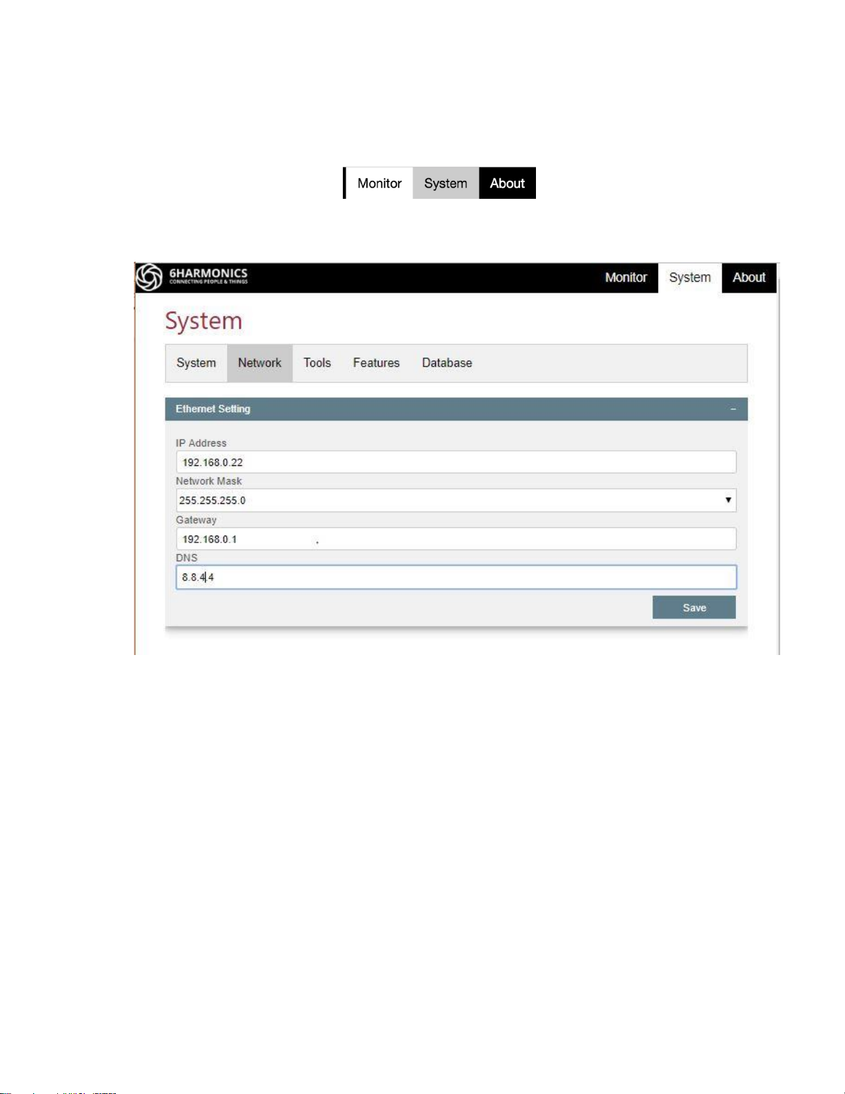
In the Monitor page, click “System” tab to access the “System” page.
Click “Network” tab.
Input the required network parameters and click “Save” button to apply the settings.
Page 35
34
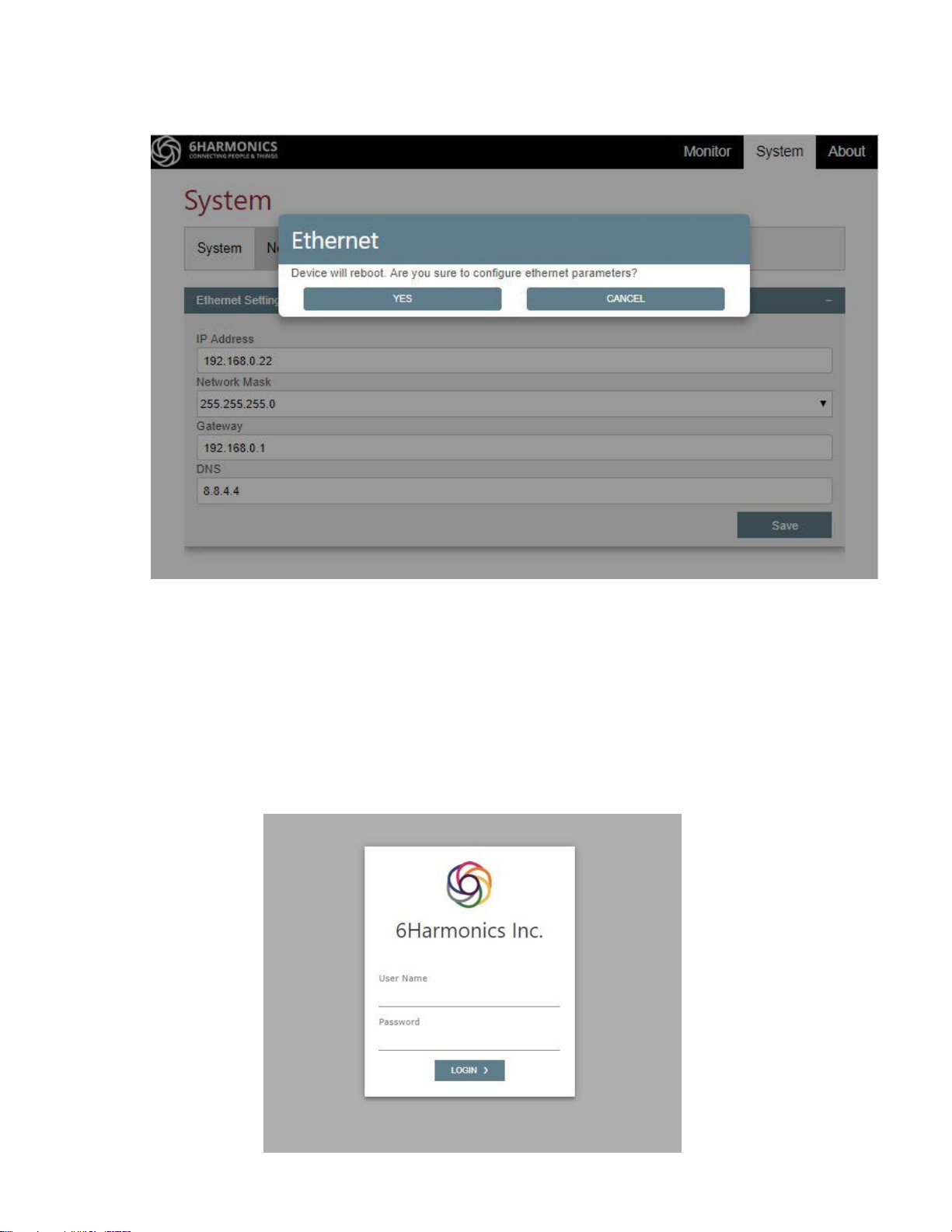
Confirm “Yes” to reboot device and apply changes.
The Chrome browser will automatically return to the login page after reboot. Make sure
your PC is on the same subnet as the GWS radio.
WARNING: The GWS radios have a Roll-back Feature which ensures that the IP
configuration cannot be erroneously entered. Unless the user successfully logs back into
the GWS radio within 10minutes of changing the IP configuration the GWS radio will rollback to the previous IP configuration.
Login and confirm the new IP setting to confirm the successful implementation of a new IP
configuration.
Page 36

35
Using the Djinni Tool to Configure the GWS Radios
What is the purpose of this tool?
Frequently installers may have difficulty finding the IP address of the radio, and as a
consequence they are unable to login to the radio. This is particularly frustrating at a CPE
install which ends up taking much longer than it should.
When a GWS radio, either a BTS or a CPE, is powered up Djinni program will run on the radio
for 10 minutes. The Djinni tool should be used within 10 minutes of power up or the radio
must be power cycled by powering down the POE midspan. Do not power cycle the GWS
radio by hot-swapping the Cate5e cable / RJ45 connector to the radio.
Installation
The computer used must have a standard RJ45 ethernet port and preferably NOT a firewire
or USB to ethernet emulator/adapter.
WARNING: some USB-Ethernet emulators do not work.
For the Djinni tool to work you must install WinPCap first.
https://www.winpcap.org/install/default.htm
Computer should be Windows 7 to 10 and support the WinPcap version used.
Please note that the later versions of Windows may take longer to authenticate an ethernet
port on a network so be aware of this.
Enabling a WiFi connection allows for simultaneous access to the internet as well as the GWS
radio.
Page 37
36
Preparation
Set the Ethernet port to DHCP or to a known fixed IP configuration.
Disable then Enable the ethernet adapter to ensure it is on the correct IP domain.
Connect the computer to the data port of POE midpsan that is powering the radio.
Check the POE lights are on = radio is powered up. If the radio has been powered up for
more than 10 minutes the tool will not work. Generally, it is best to first power cycle the
radio by removing-inserting the AC power cable12 to ensure you have 10 minutes of Djinni
time.
Using the Djinni Tool
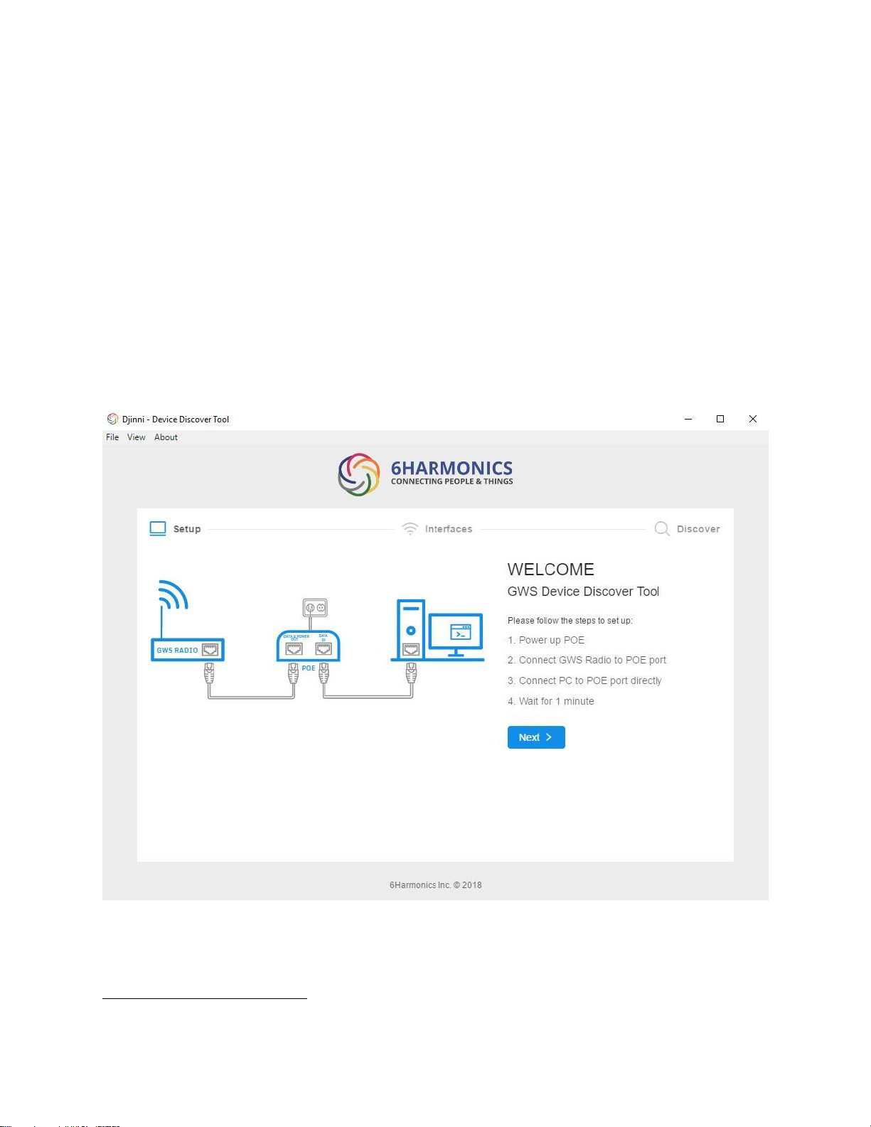
Run the Djinni tool.
Click on Next
12
Do not power cycle by hot swapping the RJ45 to the radio.
Page 38
37
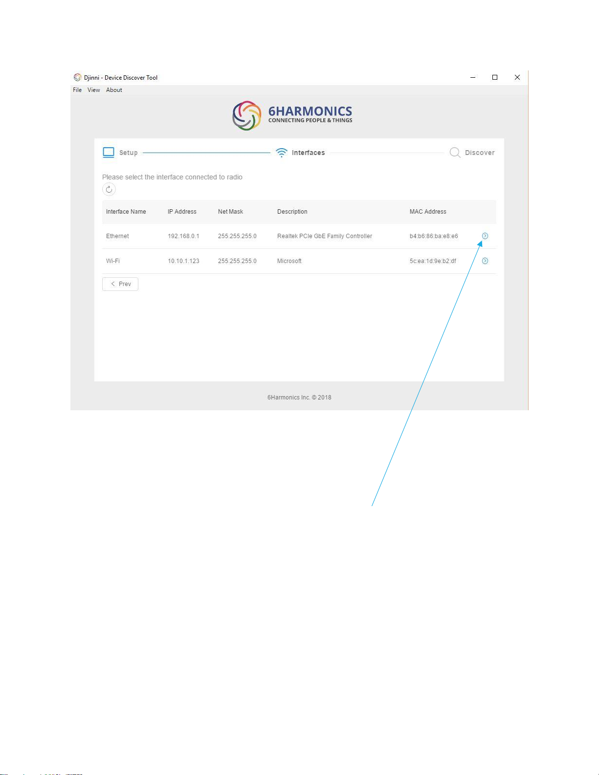
The IP address is the IP address of the ethernet adapter on the PC. The MAC address of the
ethernet adapter of the PC is also displayed. If the ethernet adapter is set to DHCP then you
may have to change the IP network configuration of the PC after the GWS radio is
configured so that both the PC and the GWS radio are on the same subnet.
Choose the adapter (ethernet) by clicking on the blue arrow.
Page 39
38
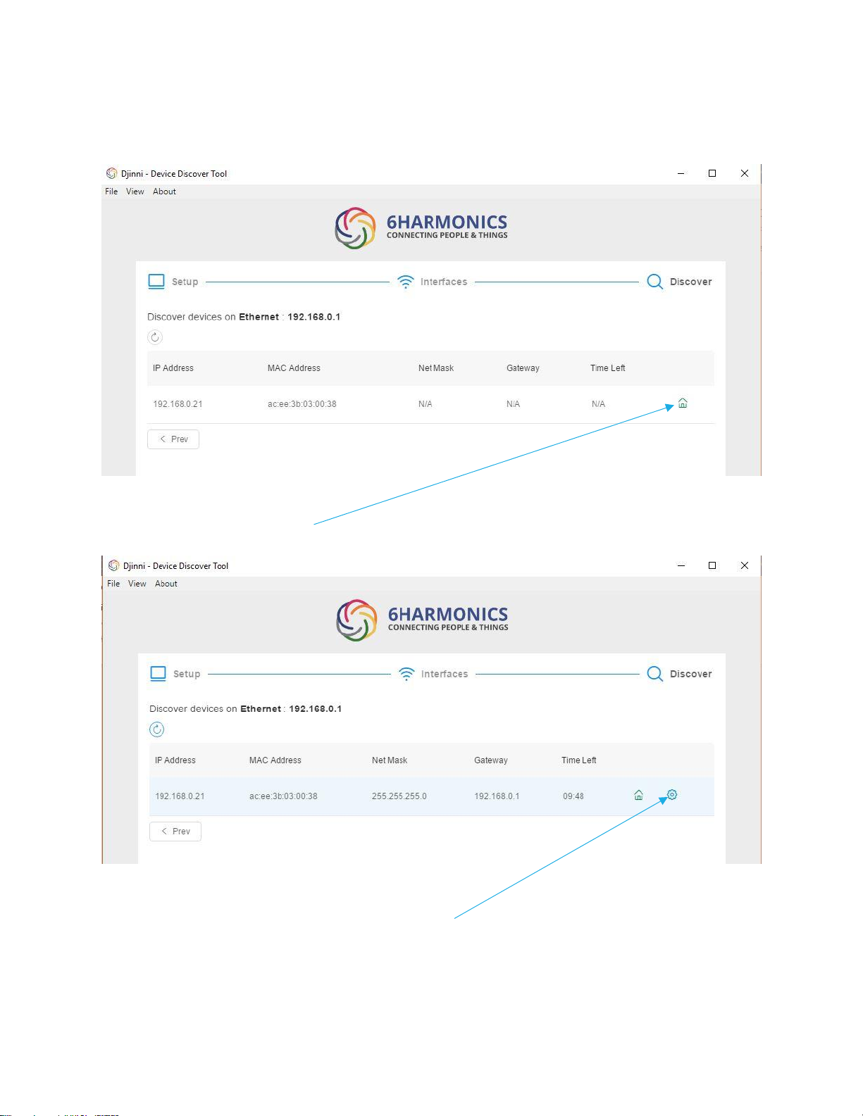
The radio IP will be displayed. In the case displayed below the Djinni time on the radio has
expired.
If the laptop and the radio are on the same subnet (as above) you can click on the GUI icon
and it will open the radio GUI. (GUI icon only appears if on same subnet as PC).
If the laptop is not on the same subnet you must reboot the GWS radio.
Repeat and the configuration icon should appear.
Page 40
39
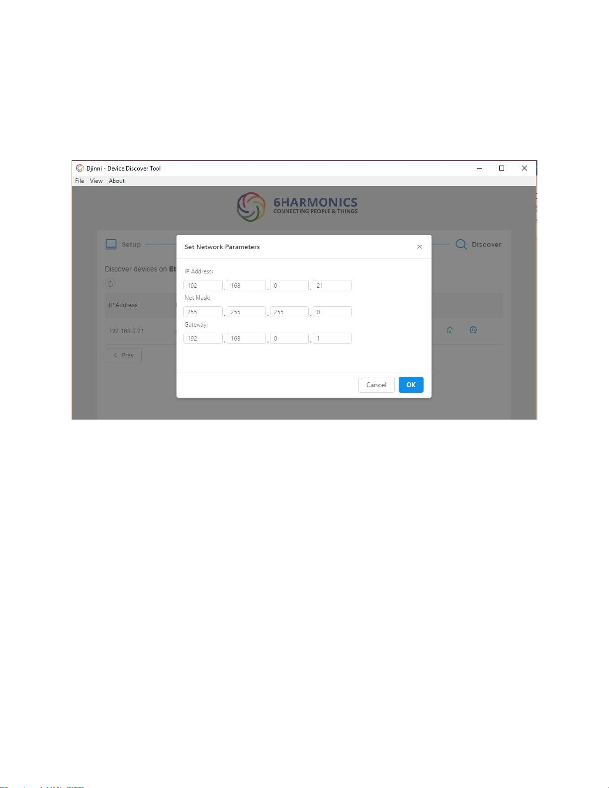
Note “Time left” refers to the amount of time that remains for the Djinni tool to run on the
GWS radio. Even if the laptop and the GWS radio are on completely separate subnets you
will still be able to login into the GWS radio. Click the configuration icon.
The window below appears:
Set the IP address, the network mask and gateway to the required values.
Please note that you know from the earlier Djinni pages what the configuration settings of
the ethernet adapter are. Therefore, you have confirmed both the GWS radio and PC will be
on the same subnet. Click on OK.
Page 41
40
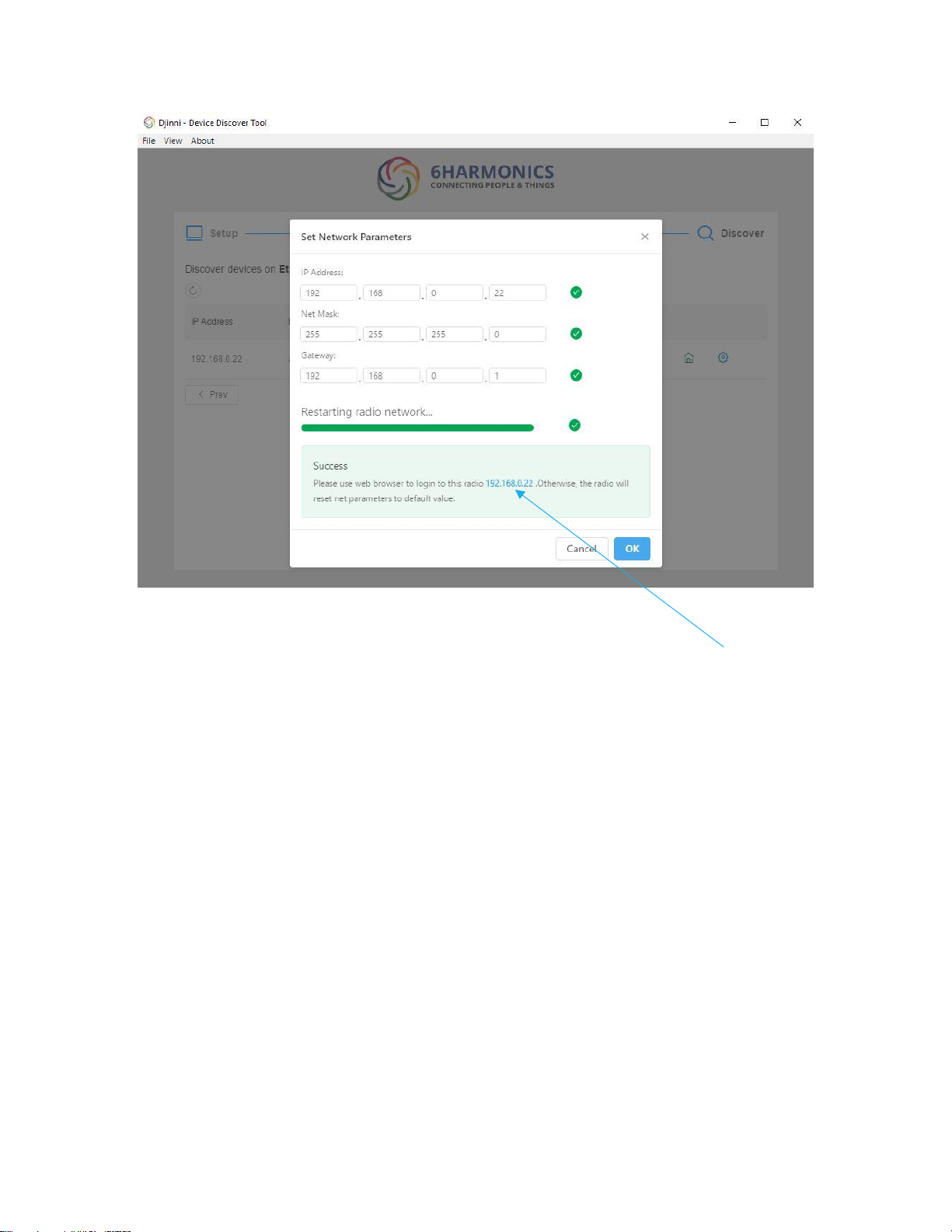
The radio will restart and overwrite the Network Parameters.
In this example the IP address has been changed from 192.168.0.20 to 192.168.0.22
Roll-back Feature
IMPORTANT: Once you save the IP configuration YOU MUST RELOG BACK INTO THE RADIO
TO CONFIRM THE IP CONFIGURATION WILL BECOME PERMANENT.
If you simply save the IP configuration and the CPE makes a link to the BTS, then data will
flow giving the impression all the IP settings are good. But after 10minutes the roll-back
feature will become enabled. In this case the IP configuration will roll-back to whatever it
was previously-and the data connection to the internet will be lost.
This roll-back feature is to ensure that in the event of a change in IP address and a mistake
being made, a user will still be able to access the radio if the Djinni tool is not available.
For example, if you are setting the IP configuration from the default to a specific setting but
a typo error is made the radio will roll back to the default and you can login.
If users do not have access to a Windows based PC the GUI method must be used rather
than the Djinni method. In this case the roll-back feature is essential in case of an input error.
Page 42
41
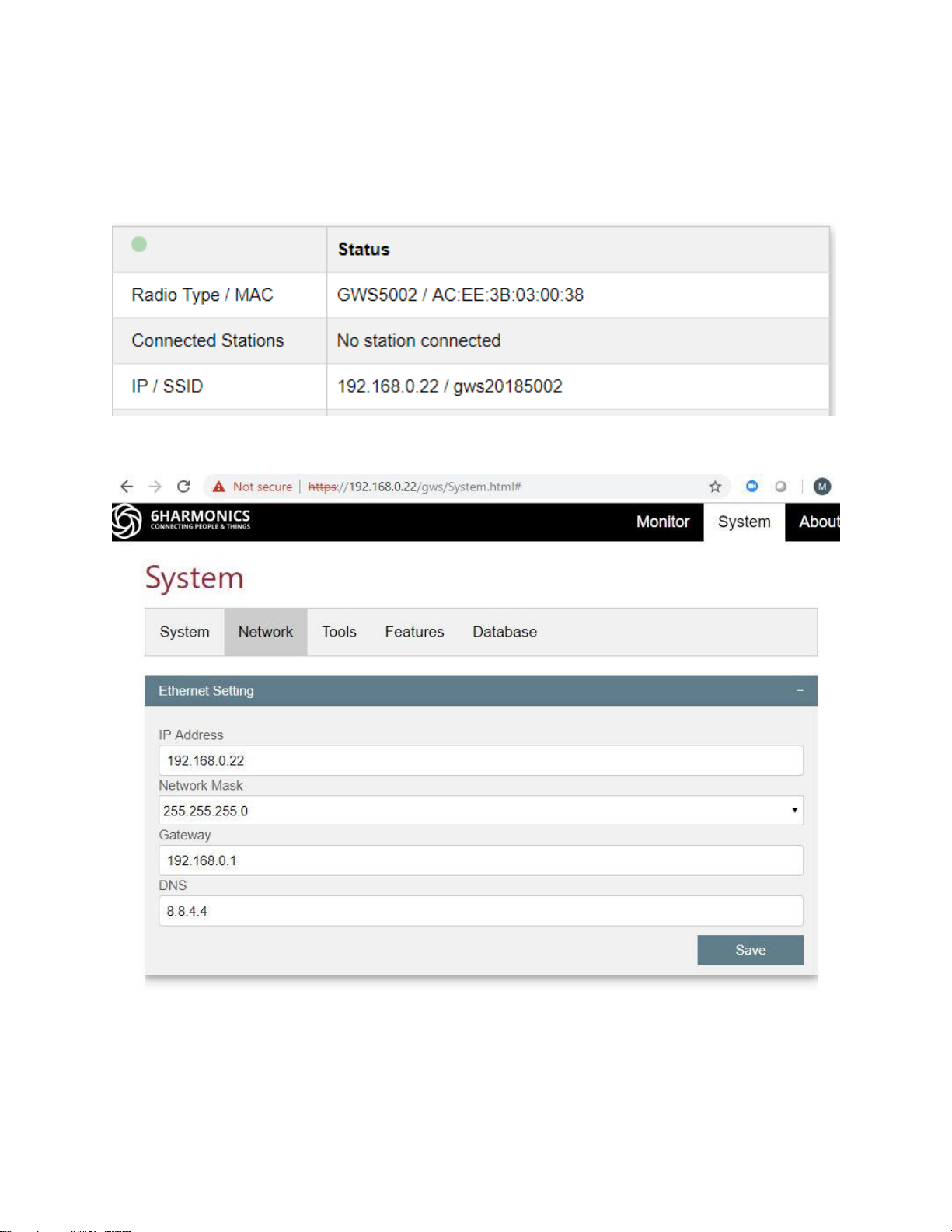
Login to the radio as normal and check the IP configuration on both the Monitor Tab and the
Network Tab.
Monitor Tab, note the IP address.
Network Tab, validate the mask, gateway and DNS are correct.
This completes using the Djinni Tool to set the Network Parameters of the GWS radios.
Page 43

42
Setting up a Radio Link
All GWS radio units share the same GWS host software. It is essential to ensure that all GWS
radios are correctly configured for the deployment scenario.
Establishing a Wireless Link between Two GWS Radios
For the purposes of this section we assume that the GWS radio is in manual mode and a
database is not used to determine the allowable operational channels.
From the proceeding section we have successfully set the IP configuration of the radios.
As the radios establish Layer 2 connections over the wireless link it is possible to have the
GWS radios on a separate VLAN for management from the service VLAN.
Typically, the service VLAN will have a DHCP server on network edge router behind the base
station to provide IP addresses to the residential routers.
The edge router port will therefore typically support:
• A management VLAN with static (fixed) IP configurations for the GWS radios
• A service VLAN with DHCP for the residential routers that provide internet
connectivity on the client side.
The residential routers will be configured with DHCP of non-routing IP addresses as normal.
Therefore, the IP configuration of the GWS radios is for two reasons only:
• Management
• Internet access to obtain channel availability from a database.
Bench Testing
If the user wishes to become familiar with the operation of the GWS radios prior to a full
installation, then a simple bench test set up is as follows:
Cable Test:
1) Connect the antenna ports of the client station and the base station radio using LMR
cables. At least 60dB of isolation should be inserted in the link to simulate the losses of an
over the air link.
2) Do not connect power to the POE midspans.
3) Connect each radio to the POE midspans using pre-tested Cat5e cables. Insertion of
ethernet surge suppressors are strongly recommended.
Page 44
43
4) Connect a PC or laptop to the data port of each midspan using pre-tested Cat5e cables.
5) Power up each midspan by inserting the AC power cord into the POE midspan.
WARNING: Do not hot swap the Cat5e cables between the radio and the POE midspan. The
radios use 4 pair POE++ and can be damaged.
6) Login and configure the radios as explained previously. Follow the steps in the following
section to establish a radio link. If the radios require database operation use the internet
connection sharing method to get access to the database.
If the radio is GPS enabled, it must be placed near a window so as to access GPS satellite
signals.
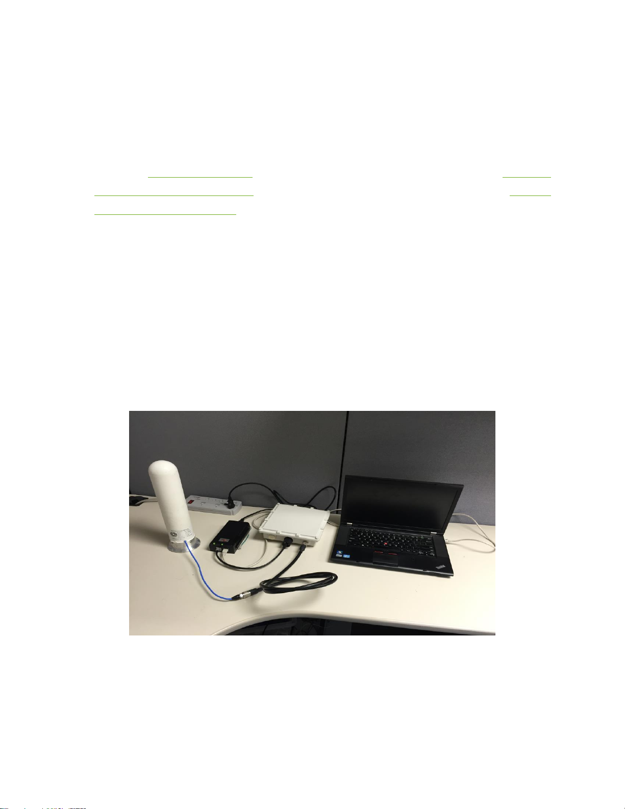
Over the Air Test:
The GWS radio should be connected to an antenna with 50 Ohm impedance.
Ensure there is sufficient space between the two radio antennas so that the receive chains of
the GWS radios cannot saturate. Placing the client station radio and the base station radio in
adjacent rooms can work well. Do not use high gain antennas that are in close proximity to
each other and simultaneously pointing directly at each other.
Over the air bench set up example using a low gain omni antenna.
Follow the same steps as the Cable Test.
6Harmonics recommends either cable or over the air benchtop testing as practice prior to
field install and set-up.
Page 45
44
GWS Radio RF Parameters to Establish Radio Link: Base Station
We assume that a base station has been carefully installed and that the PC and GWS radio IP
addresses are set to a predetermined configuration, then we need to set:
(a) the channel number (we assume a dual channel bandwidth of 12MHz)
(b) the transmit (T
X
) power
(c) the receive gain
Settings chosen should be consistent with the modelling that was performed previously.
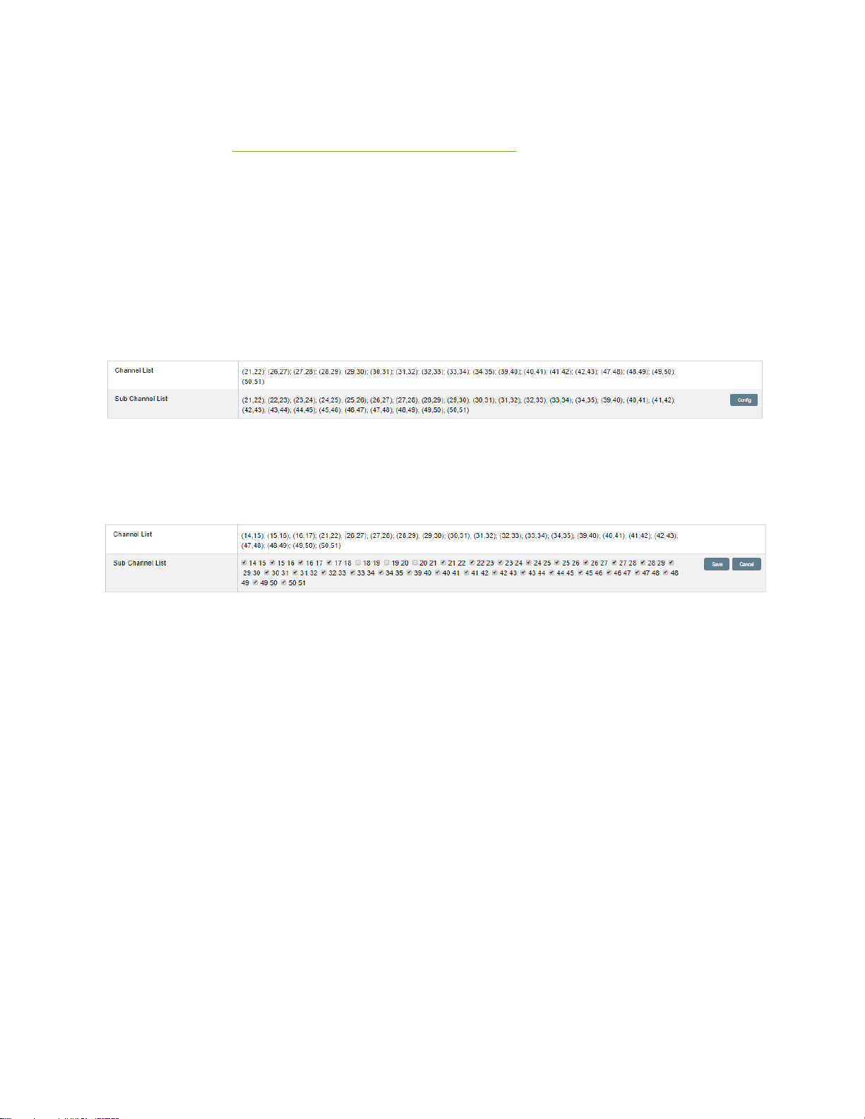
On the base station System tab, check the channel list:
The sub channel list is the list the radio can physically operate at. If you access the list using
the Config button, the list can be edited by clicking each channel to remove certain
channels.
In this case, the channel list has been manually edited to eliminate 18,19; 19,20 & 20,21 as
available options in the channel list. If the channel list is edited in this manner the channels
will not appear in the pull-down menu in the Radio Status section of the Monitor tab.
Why would you do this?
(a) To stop this particular base station roaming onto a particular channel in the event of the
database making the preferred channel unavailable.
(b) To stop this base station operating on a channel that is known to suffer high levels of
noise or interference.
Having checked that the appropriate channel list is available we now set the channel on the
Monitor tab.
However, before we choose an available channel, we need to check the channel quality.
Page 46
45
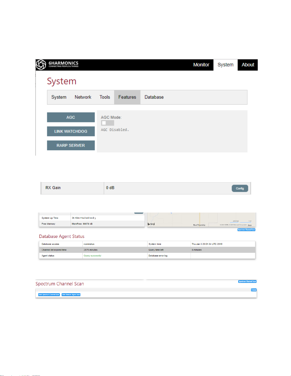
Go to the Features sub-tab from the System tab.
Disable AGC.
On the Radio Status section of the monitor tab, use the Config button to set the Rx gain to
zero and Save. The RX Gain should display zero as below.
Click on the Spectrum Channel Scan button on the Monitor tab:
The Spectrum Channel Scan window appears:
Click on the Start Spectrum Channel Scan.
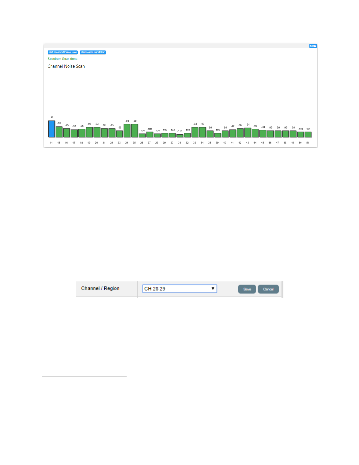
The radio will then check the noise in all channels, even though the database or the subchannel list may not allow use of some channels.
Page 47
46
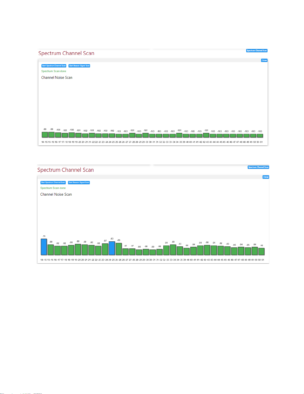
A very clean scan example (12MHz channel width):
A scan with some other signals (12MHz channel width):
The scan suggests TV signals on channels 14 and 24, maybe 23 or 25, that impact the noise
floor in 14,15 and 24,25. Because TV signals are very strong, and their emissions mask is not
perfect we also see bleed in to 15,16 as well as 23,24 & 25,26.
We can check this further by reducing the channel bandwidth to 6MHz and repeating the
scan.
Page 48
47
Now we can see the TV signals on 14, 24 and 25. Maybe 33 and 34 also.
TIP: Always save these scans for a base station and a client station at time of install. If
noise or interference arises at a later date it will be obvious if any changes in RF
environment have impaired the link. Secondly, the TV signal acts as a marker to show the
antenna and associate receive circuitry of the radio are fully functional. If, for example,
water gets into one of the RF connectors because of poor waterproof taping, you will see
a loss of receive signal strength of the TV channel transmission13. TV channel transmissions
tend to be very stable14 and so can be used as receive signal markers.
Based on these scans channel 28,29 looks a good choice for 12MHz transmission bandwidth.
We set the channel to 28,29 and click on Save.
13
If, for example, there is water in the RF chain of a base station, the values of the TV signals markers on the
channel scan at the base station will diminish. The RSSI at the client station will also diminish. But the TV signal
markers at the client station will not change. This procedure allows identification of which end of the link has a
problem in the RF chain-but this is only feasible if a baseline status of the RX signals is recorded at install.
14
This assumes direct propagation as opposed to tropospheric propagation which can vary widely during the
day or with weather conditions.
Page 49
48
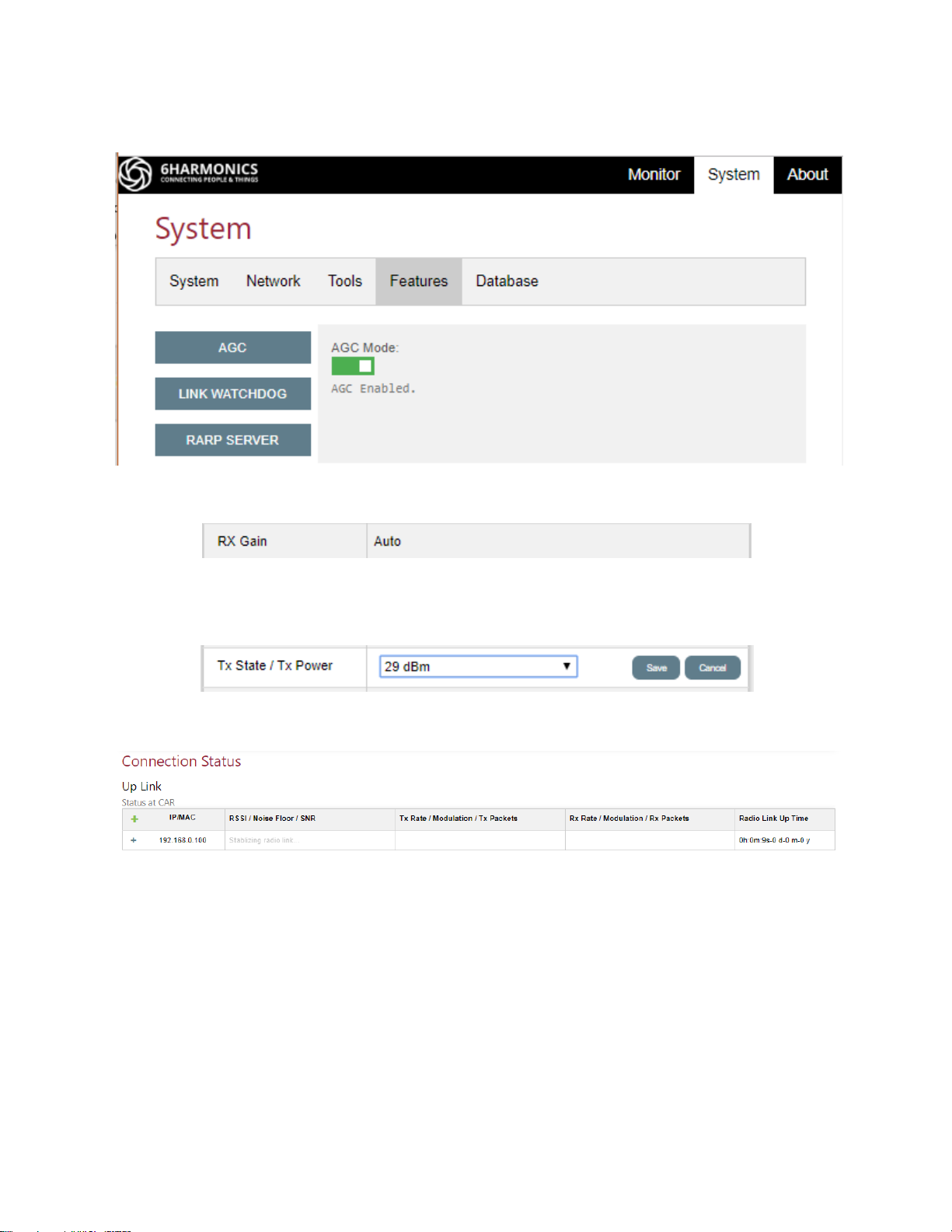
We re-enable the AGC on the Features sub-tab of the System tab.
Radio Status section on the Monitor tab will now show Rx Gain setting as Auto.
We set the transmit conducted power to a high value, say 29dBm (assuming the database
allows this conducted power / EIRP value). Click on Save.
If the client station scans onto this 12MHz transmission, the link will appear as below:
The status will display “stabilizing radio link” for approximately 2 minutes. This is because
the channel state algorithm has to run for a sufficient period of time so that the data
displayed is valid. Any data displayed immediately after connection is erroneous.
Page 50
49
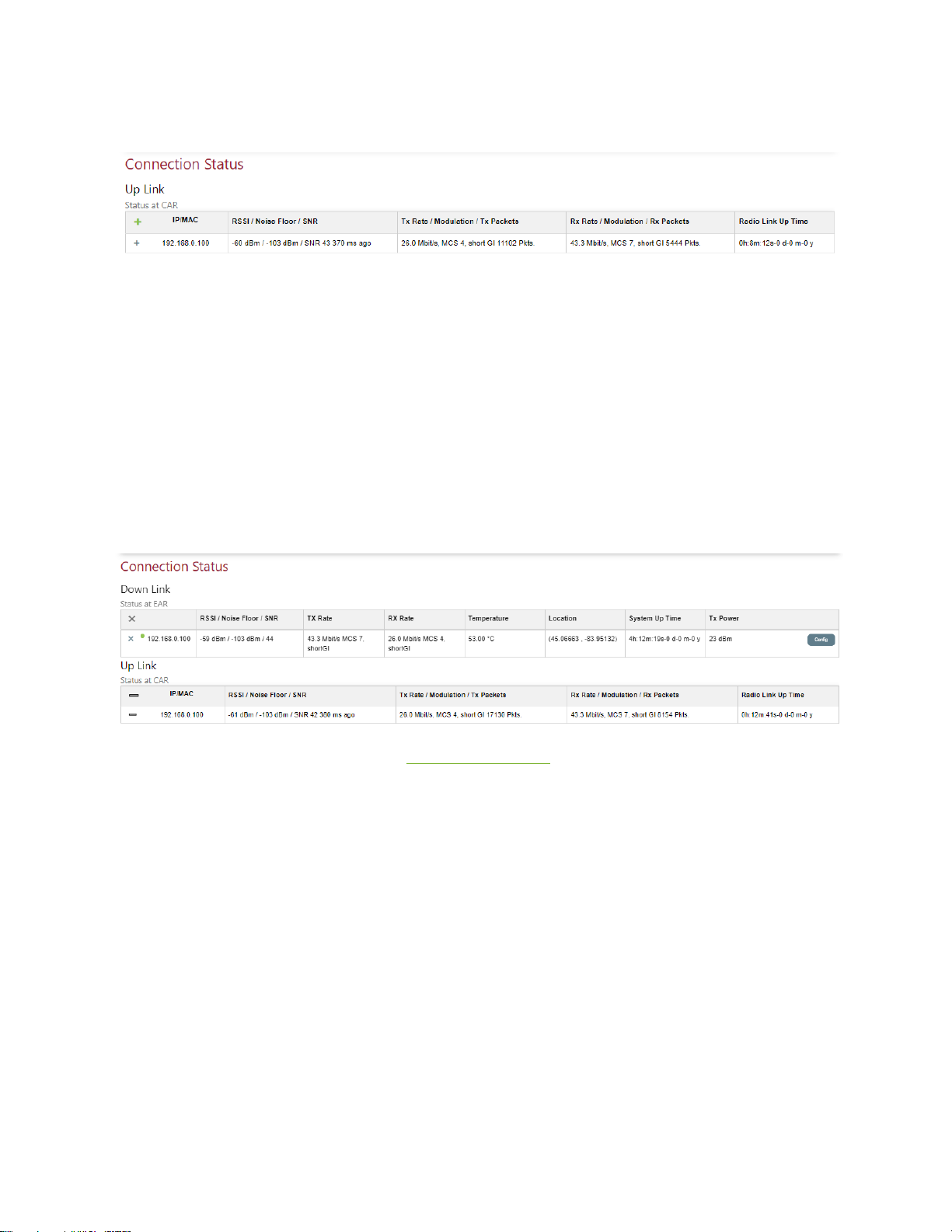
After two minutes we see:
This says we have:
-61dBm receive signal strength, -103dBm noise; SNR 43 dB
In downlink (the base station transmission) MCS 4
In uplink (the base station receive) MCS 7
The link has been connected for 8 minutes and 12 seconds
If we click on the green cross we can also see the data at the client station displayed on the
base station Monitor tab:
For further details on the display see Connection Status section of the Monitor tab
Page 51

50
GWS Radio RF Parameters to Establish Radio Link: Client Station
We have now manually configured GWS radios base station channel, transmit power and
receive gain.
In this test set up we can see the link has been successfully established.
However, in a real deployment the base station will be pre-configured based on:
• Channel availability
• Channel quality
• Simulations to determine the required coverage/range
The simulations will include the antenna gain of both the base station and the client station
and the antenna height above ground level (AGL).
Assuming the simulation shows that sufficient signal can be obtained at a prospective client
location a truck roll is initiated, and the client station radio and antenna installation will be
performed.
The following procedure explains how to connect to the base station when logged into a
client station.
Login to the GWS radio and configure the IP as described previously.
Page 52
51
Base station towers typically have multiple base station radios on a sector type architecture.
As the client station radio has a scan function, we need to pick the correct base station by
looking for the beacon signal from the preferred base station.
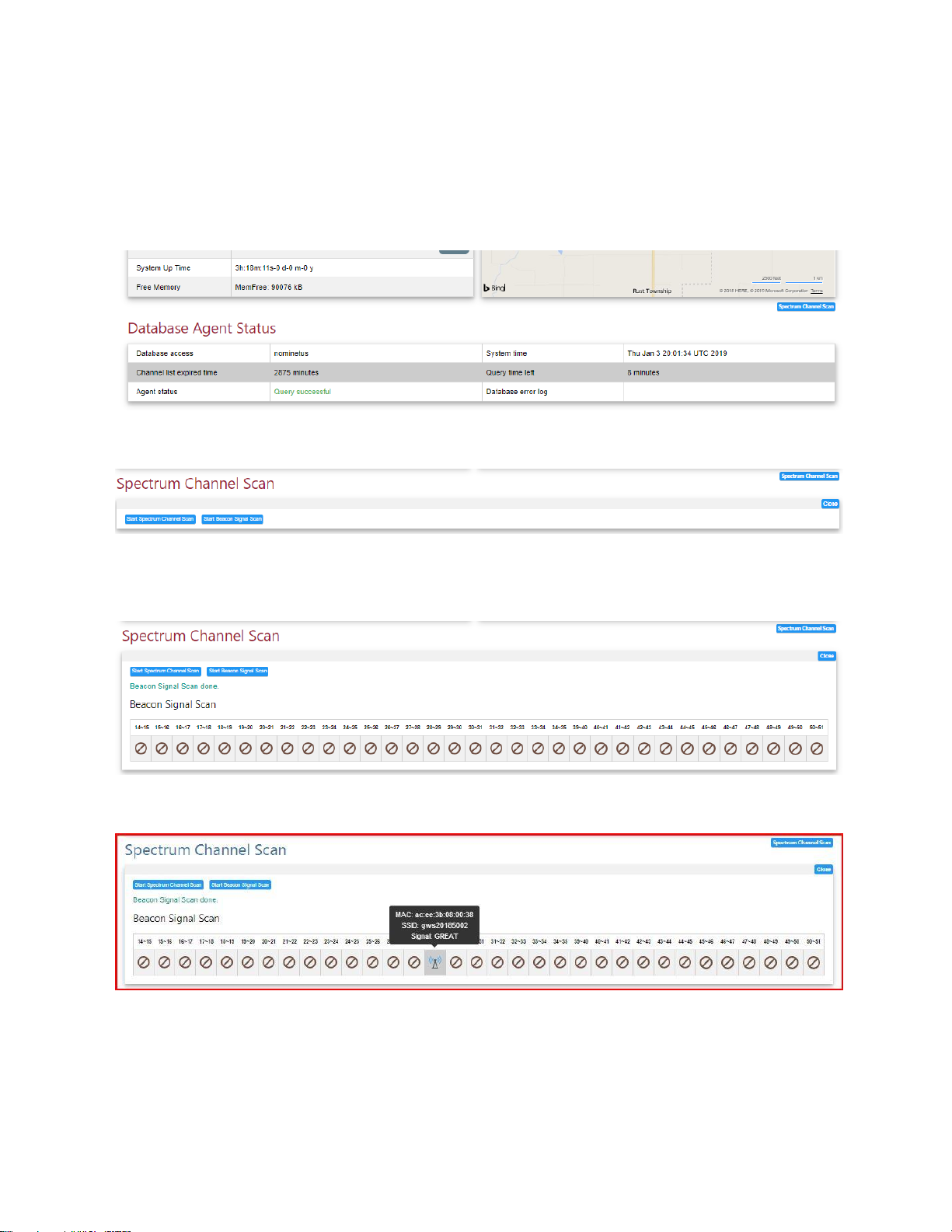
Click on the Spectrum Channel Scan button on the Monitor tab:
The Spectrum Channel Scan window appears:
Click on the Start Beacon Signal Scan.
Below, a scan with no visible beacon:
Below, scan with a beacon on Ch 28,29:
The client station radio beacon scan will show all the beacons it can see, displaying the
relative signal strength, the MAC address and the SSID of each base station.
Page 53
52
Place the cursor on the signal strength icon to display the MAC address, the SSID and the
signal strength from the base station on given channel.
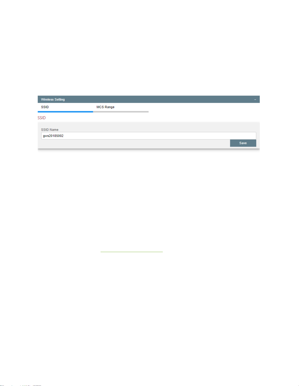
Once you have determined which base station you want to connect to, set the SSID on the
Network sub-tab of the System tab.
Click on Wireless Setting to display the wireless settings window.
Enter the SSID of the base station you wish to connect to and click on Save.
Return to the Radio Status section of the Monitor tab and set the channel as displayed from
the beacon scan. If you do not set the channel the client radio will automatically begin to
scan and will connect to the base station once the channels/SSID are the same.
The client station radio should connect and will undergo the 2minute stabilization before the
radio link parameters are displayed.
Repeat, if necessary, for alternative base stations.
The operator can then evaluate which base station this specific client station radio should
connect to on the basis of optimal link performance.
WARNING: When a client station scans and connects to the base station the SSID and other
network credentials must be validated before the connection will stabilize. This takes
approximately one second. If a client station scans onto a base station and connects very
briefly(~1second) this indicates a network authentication issue where the client radio isn’t
allowed to connect to the base station. Check the SSID settings on both the base station
and the client station. Check IP configuration for the base station and the client station to
see that they are on the same subnet.
Page 54

53
Radio Link Performance Optimization
After the link is established if the information from the monitor window shows that the
performance is not as expected by the simulation then we may need to tune the link to
ensure good performance.
Causes of link asymmetry may include:
• Transmit power settings
• Receive gain settings
• Noise at the client station
• Noise at the base station
• Asymmetric antenna gain
Reduction in MCS can be caused by:
• Interference even though the SNR value appears good. In this case the MCS value will
lower than expected as per the table of expected throughput performance.
• The transmit power is too strong, the signal may get saturated and the link will show
poor throughput performance.
• If the link signal is too weak, for example if the RSSI is below -80dBm, then the T
X
power should be increased until the RSSI is above -80dBm.
A RSSI of -50dBm to -80dBm and an SNR>25 are considered optimal.
Wider channels will, of course, have higher noise floor, and also the probability increases of
picking up an interfering signal.
As explained previously if the link is not reciprocal i.e. where one receive RSSI is too high,
and the other receive RSSI is too weak, then the TX power at both GWS radios may need to
be adjusted to balance both RSSIs to get a good overall performance in both uplink and
downlink. In some cases an assymmetry of 6dB or two MCS levels is acceptable. However, it
depends upon the relative uplink/downlink traffic patterns and the aggregate load of the
base station.
Page 55
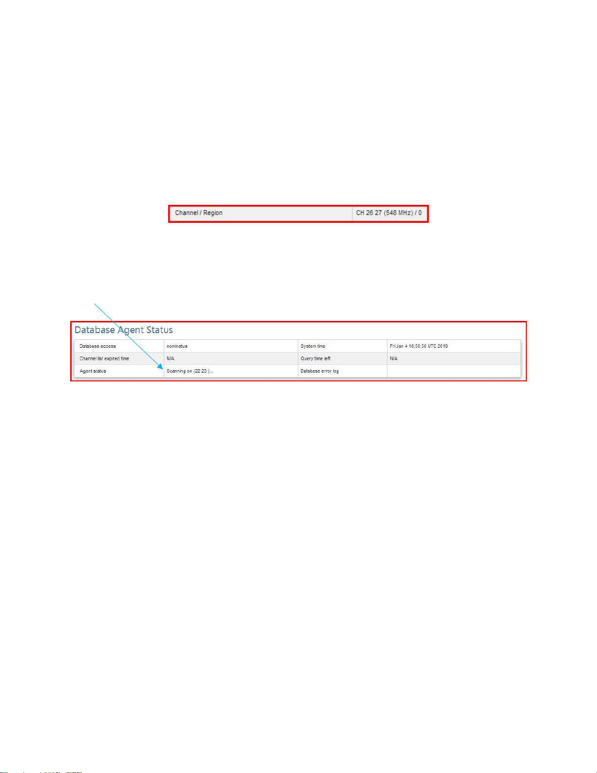
54
Scan Function
As mentioned previously, the GWS client radios have an automatic scan function.
On start up the client radio will automatically try the last valid configuration to estblish a link
and if no link established, the CPE will go into scan mode and look for a base station to
connect to.
The Radio Status display is as follows:
The user will see the channel number change every few seconds.
If the radio uses a database, the user will also see that the channel scan function is
operational in the Agent Status part of the Database Agent Status section on the Monitor
tab.
TIP: If the radio link is broken for more than 5 minutes, for example due to a power outage
at the base station location, the client station will automatically go into scan mode.
The client radio will continue to scan channels until it finds a base station with the same SSID
and a sufficient signal strength provide enough data throughput to undergo a database
query.
If there is more than one base station with the same SSID within range of the client station,
then a client could possibly roam onto a different base station than the original connection.
This arrangement can be used as a back up in case a base station fails. Conversely, in the
event of a power outage or power cycle at the client station this may result in too many
clients attaching to a single base station and will create a load balancing issue.
NOTE: In the event of a power outage the client radio will reboot to the last operational
configuration, it will attempt to re-connect to a base station using the same SSID and
channel prior to power down. If the attempt to connect to the base station using the last
good configuration fails it will go into scan mode only after 5 minutes. This feature
minimises the probability a client radio will connect to the wrong base station, even if
multiple base stations have the same SSID.
Page 56
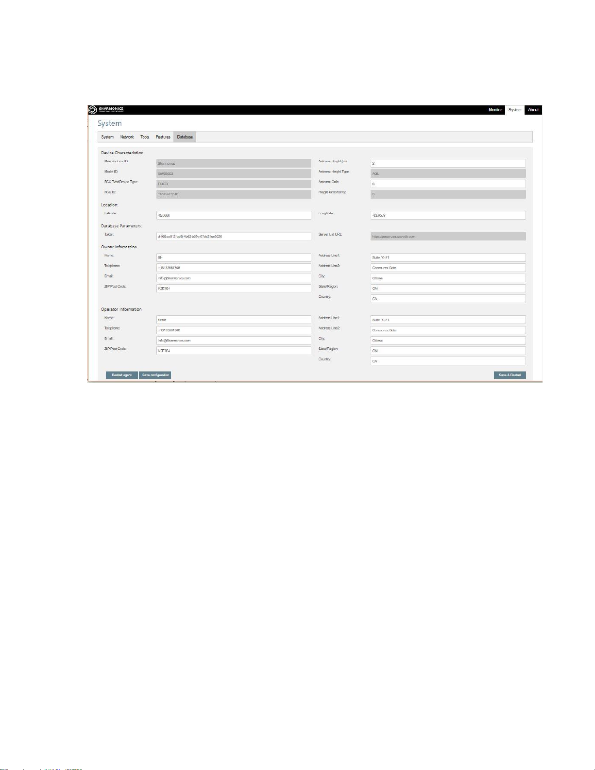
55
Nominet Database Settings: FCC Operation
In “System” page, click “Database” to configure database agent.
Device Characteristics
The antenna height above ground level (AGL) in meters is required. The maximum legal
height AGL is 30m (approximately 100ft).
The antenna gain, is the NET antenna gain and includes losses due to cables etc. The antenna
gain is used to calculate the maximum EIRP allowed for the GWS radio at this specific
location. If the gain of the antenna plus the conducted power exceeds the maximum
allowed EIRP at this location the radio will not turn on.
Location
The longitude and latitude are entered as decimal degrees. Location should be specified to 6
decimal points. The location can be checked on the map on the Monitor tab. For locations
west of the Greenwich meridian a minus sign is required. Please ensure no spaces or bad
characters.
Page 57
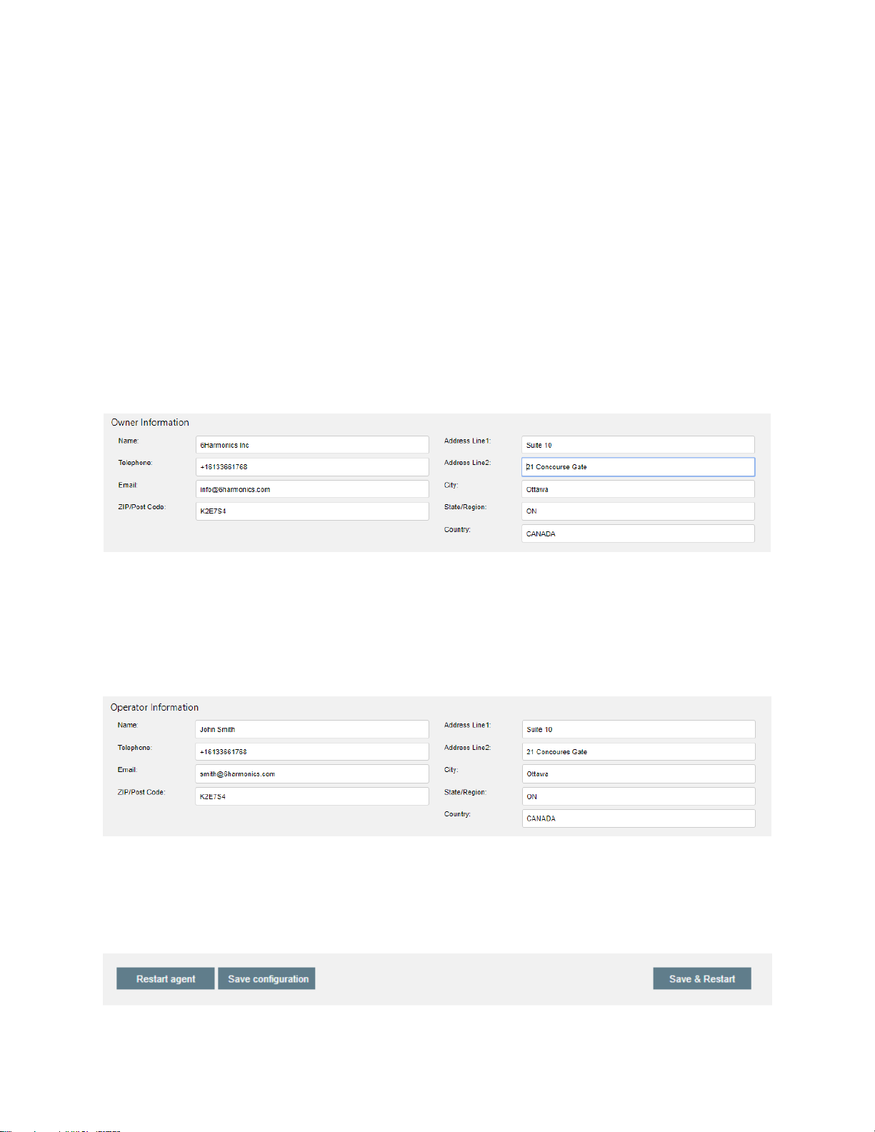
56
Database Parameters
The database token is inputted during manufacture and the token lifetime is activated after
a number of database queries as determined by the database provider. The lifetime of the
token is determined at equipment ordering and is typically 3 or 5 years.
WARNING: Changing parameters in this field may cause the radio to discontinue operation.
Owner Information
The owner information relates to the legal owner of the equipment, typically this is a
company.
Be careful with the correct information as it is an FCC requirement to provide accurate
information.
WARNING: Ensure the format is correct.
Operator Information
The operator refers to the person who is responsible for the actual operation of the radios.
Typically, this is an employee of the company that owns the radios.
Ensure format is correct. The telephone number requires the international format of + and
country code. (USA is +1 before the area code/local number)
There are three options to save & implement changes.
Page 58
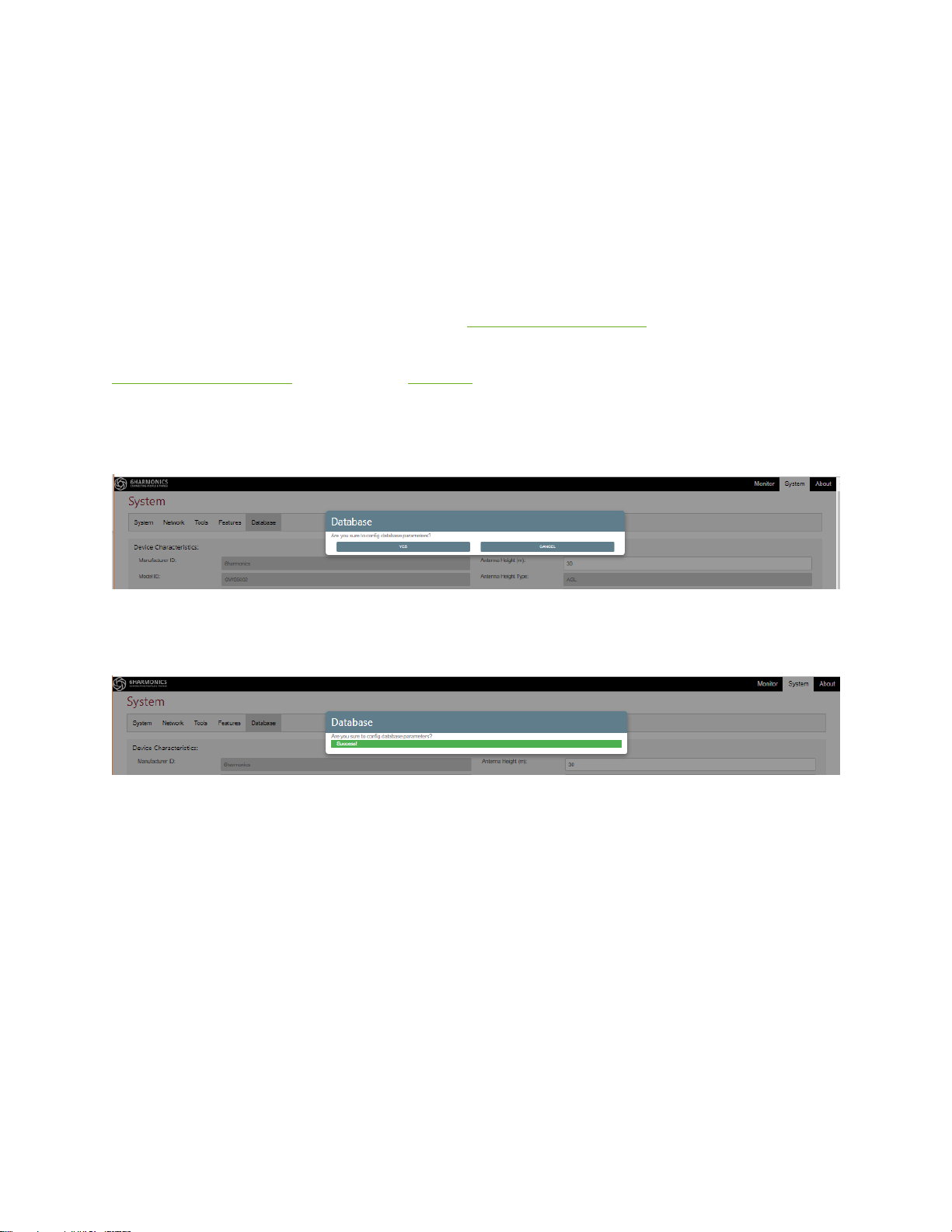
57
Restart Agent: Use this button if you are trying to check that the radio is able to reach the
database.
Save Configuration: This button will save changes to the database parameters but will not
initiate a new database query. The radio will wait until the current channel list has expired
and will then query the database.
Save & Restart: Saves all the changes and initiates a new database query, and if successful
will restart the “Query time left” timer in the Database Agent Status section of the Monitor
tab. If there are errors in the database parameter error messages will appear on the
Database Agent Status section of the Monitor tab.
WARNING: It is preferable to always use the Save & Restart button to ensure that both
changes are saved AND that the next database query will be successful.
Click on YES, and then wait for confirmation that the changes have been successfully
implemented.
Finally, go to the Monitor tab and check the database query was successful.
Page 59
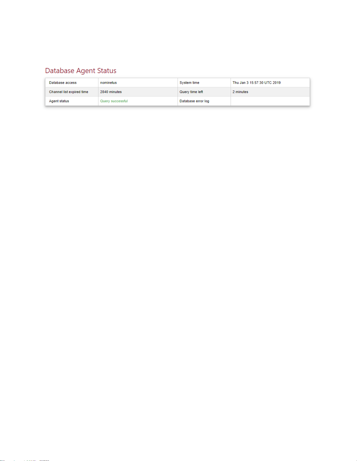
58
Database Operation: Base Station
Click “Monitor” tab to access the Monitor page.
• Agent status shows “Query successful” which means the radio has successfully accessed
the database and completed the query process.
• Query time left is the time to the next database query.
• Channel list expired time is a count down timer on the validity of the channel list on the
database. The channel list availability is periodically updated (say 24 or 48 hours) at the
database, typically the database pulls data from broadcasters or other regulator
databases to ensure the database itself is valid. This value is a parameter that is returned
form the database and is displayed as part of the database query process. It is regulatory
domain specific.
Page 60
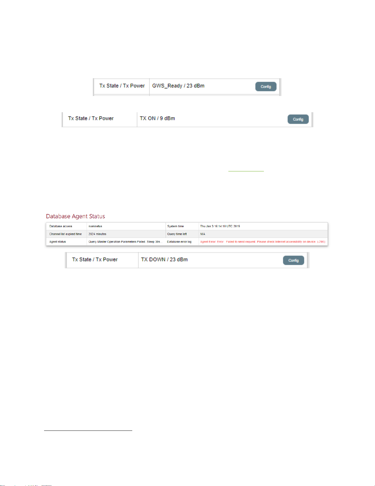
59
The operator should observe the following:
TX of the base station will not be turned on until the valid channel list is returned from the
database. This is indicated by the Tx state indicating GWS_Ready or TX ON15.
OR
If the current channel is within the channel list, the base station will start to transmit on
current channel.
If current channel is not within the channel list, the base station will choose the next
available channel to operate. Check the Channel List on the System Tab. Please note the
base station has a channel list and a sub-channel list.
If an error is returned from database, the TX status of the base station will be immediately
changed to Tx Down.
The operator must then determine the root cause of the failed database query.
15
Earlier versions of software say “GWS_Ready”, later versions say “TX ON”
Page 61
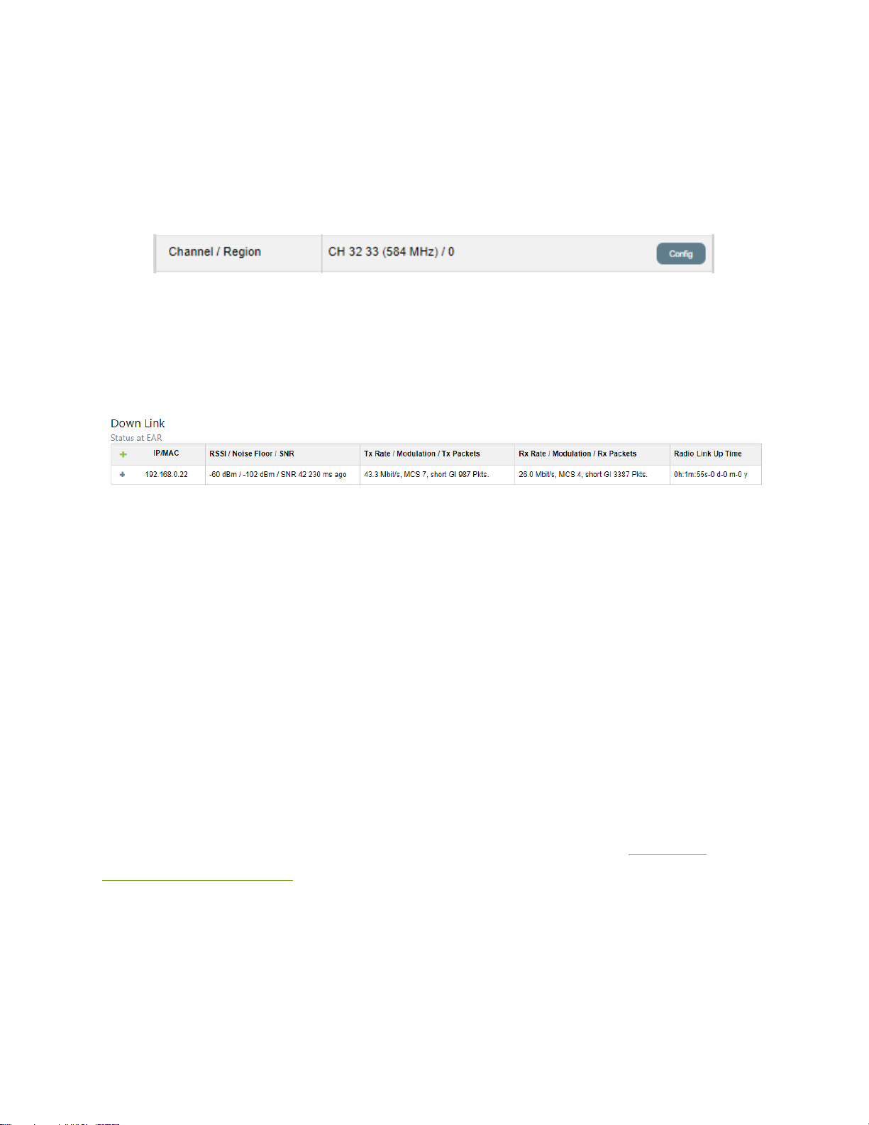
60
Database Operation: Client Station
Follow the same steps as the base station to configure the database agent for the client
station.
The operator should be able to observe on the Monitor Tab that the client station has
started to scan the full channel list.
The user will see the channel number change every few seconds.
Once the client station is on the same channel as the base station, and assuming there is
sufficient signal to make a connection, you will see the link details in the Connection Status
section of the Monitor Tab of the client station.
Immediately, the client station will attempt to query the database through the radio link to
the base station.
If the query is successful, the client station radio will operate on the valid channel (Tx state
will become TX ON or GWS_Ready ). If it is not successful after approximately 30-40 seconds
the client radio will continue to scan for another base station.
WARNING: It is possible for a client station to implement a successful database query, but
the client station may not be allowed to operate on the same channel as the base station.
This base station-client station allowed channel mismatch is rare but does happen. Before
deployment it is important to check that the proposed client station location can operate
on the same channel as the base station using the Nominet Database Tool.
Check the Channel List on the client station radio System tab.
Please note on a client station radio only the channel list is displayed. See Radio Link
Performance Optimization.
Page 62

61
Nominet Database Settings: OFCOM Operation
Although most of the software for a GWS radio operating on an OFCOM database is the
same as a radio operating on a FCC database there are several key differences which need to
be understood.
• The channel plan is based on 8MHz channels not 6MHz channels.
• The maximum EIRP is always 36dBm per 8MHz channel, there is no allowance for
higher antenna gain to increase to 40dBm per 6MHz channel as permitted by FCC in
rural areas.
• The base station radio must be GPS enabled to comply with EN 301 598 V2.1.1
16
, the
White Space Devices (WSD) Harmonized Standard covering the essential
requirements of article 3.2 of Directive 2014/53/EU i.e. a GPS is required under the
applicable EN Standard under the Radio Equipment Directive 2014/53/EU.
• Under FCC the EIRP limit for an available channel depends only on antenna height
and geolocation. It does not depend upon if the radio is a client station or a base
station. Under OFCOM, channel availability depends upon if the radio is a base station
(which must be GPS located) or a client station (GPS location is optional). The base
station uses Master Operating Parameters (MOPs) from the database. If the client
radio is GPS enabled, it may use Specific Operating Parameters (SOPs) or General
Operating Parameters (GOPs). If the client station is not GPS enabled, it may only use
General Operating Parameters (GOPs). Generally speaking, GOPs are more limited
than SOPs17.
• For OFCOM / ETSI, the emissions mask is classified into 5 levels, Class 1 to Class 5, with
the most restrictive adjacent channel leakage ratio being achieved by a Class 1 device.
• For OFCOM / ETSI the device type also defines channel availability. A Type A TVWSD is
a device that is intended for fixed use only. This type of equipment can have integral,
dedicated or external antennas. A Type B TVWSD is a device that is not intended for
fixed use and which has an integral antenna or a dedicated antenna18.
16
See Section 4.2.10 https://www.etsi.org/deliver/etsi_en/301500_301599/301598/02.01.01_60/en_301598v020101p.pdf
17
Generally speaking, but in some locations client station GOPs have higher allowed EIRP than SOPs. Always
check the database.
18
See EN 301.598 V2.1.1 Section 4.2.2 “The equipment and the antenna shall be designed to ensure that no
antenna other than that furnished by the responsible party shall be used with the device”. This means for Type
B operation only antennas form 6Harmonics may be used.
Page 63

62
• The operating frequency range of the GWS radio is greater under OFCOM. 470-
698MHz for FCC (Channels 14-51 inclusive); 470-774MHz for OFCOM (Channels 21-58
inclusive).
GWS radios have an emissions mask that is software defined. Both the base station and
client station are GPS enabled. This ensures the maximum spectrum availability in the field.
Page 64
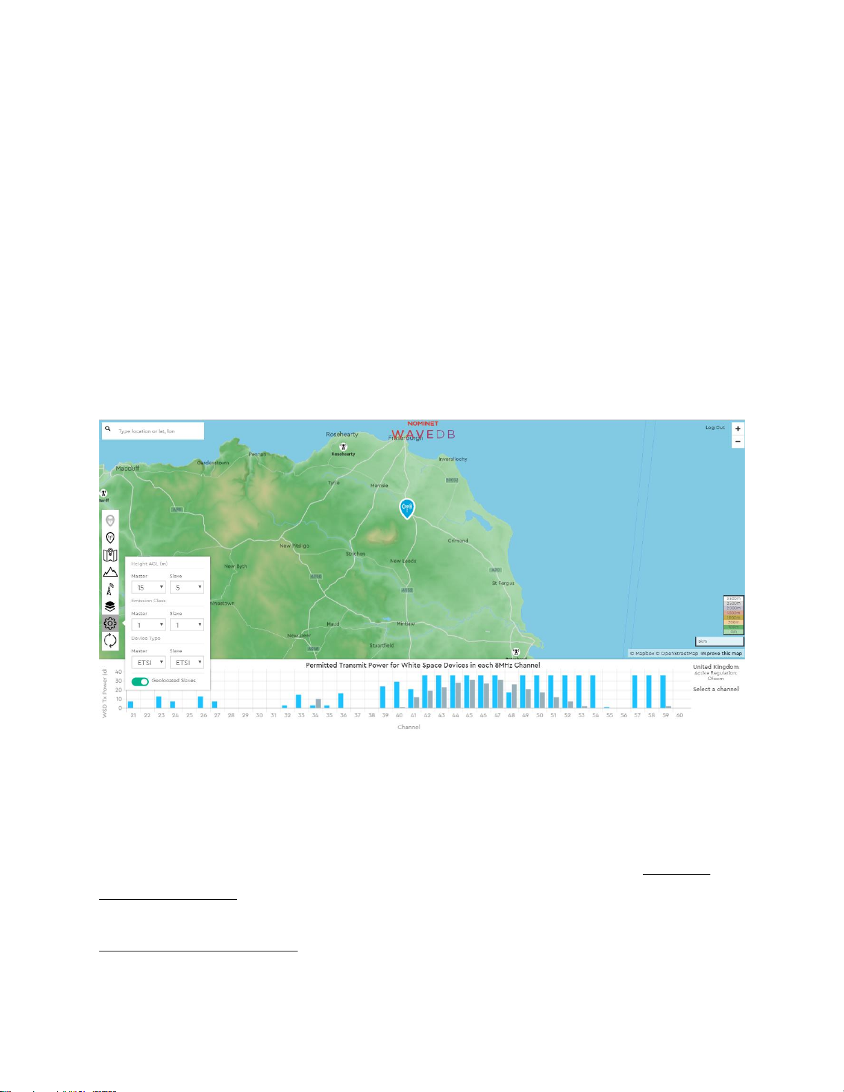
63
Understanding MOP, GOP & SOP Values from the Nominet Database
In order to fully comprehend how the MOP, GOP and SOP values determine network
operation we can explore some examples using the Nominet database planning tool19.
Understanding MOP, GOP and SOP is key to operating the radios.
Let us choose the following locations:
Base Station: Latitude 57.6198; Longitude -2.0026
Client station20 #1: Latitude 57.6486; Longitude -1.9208
Client station #2: Latitude 57.6600; Longitude -2.0080
We drop the base station pin on the map, and the tool generates the following spectrum
availability:
The blue bar chart shows the MOP channel availability, the EIRP per channel, with a 15m AGL
antenna height. These are the MOPs at the base station location.
Since the client radio obtains GOPs from the base station, the tool also displays the GOP
channel availability for the client stations. The grey bar chart is the EIRP transmit limit per
channel with a 5m AGL antenna height. These are the GOPs, and the GOPs are not client
location dependent.
19
Contact Nominet for further information.
20
The Nominet tool uses the terms Master and Slave for base station and client station respectively.
Page 65
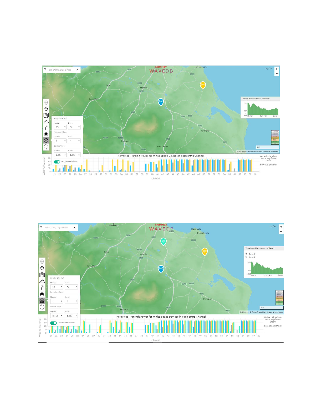
64
Consider Channel 43, the MOP transmit EIRP is 36dBm, the GOP transmit EIRP is 22dBm.
Now we add a potential client location at 57.6486, -1.9208 (yellow).
In addition to the MOP of the base station (blue), the GOP of any client station (grey), the
tool also displays the SOP for specific geolocation of client#1 (yellow).
On Channel 43, we now know the allowed SOP transmit EIRP for Client #1 is 36dBm.
If the operator chose Ch 43 there is a significant potential mismatch in SNR in UL from client
#1 depending on if client #1 uses GOPs or SOPs.
Page 66
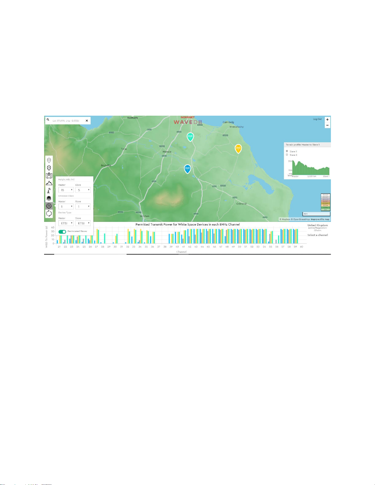
65
In summary;
• The base station can transmit at 36dBm on Channel 43
• The client station can transmit at 22dBm on Channel 43, if the client uses GOPs
• The client station can transmit at 36dBm on Channel 43, if the client uses SOPs.
Let us add another client location (pale green) at 57.6600, -2.0080.
Similarly, for Channel 43, at the location for client #2, the radio is allowed to transmit at
36dBm EIRP (pale green). If we select Channel 43 on the channel bar chart, the tool then
simulates the link performance.
Page 67
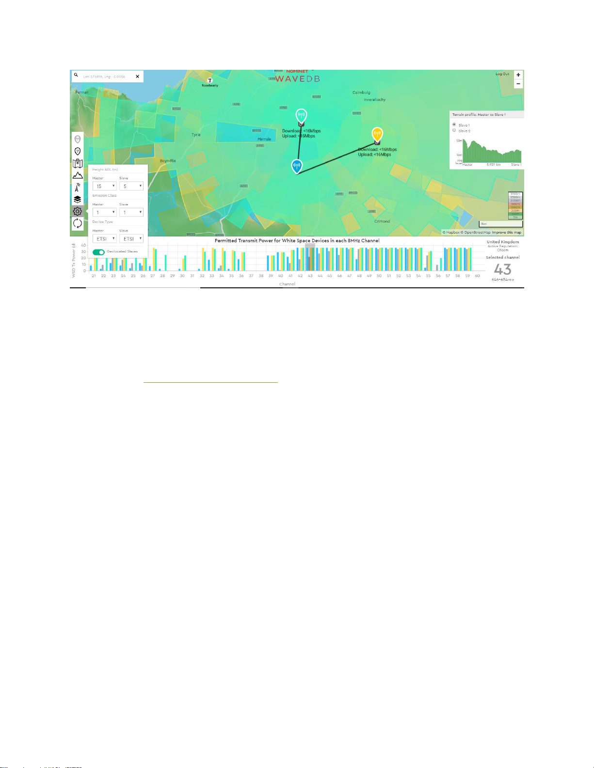
66
Each link is symmetrical (i.e. UL & DL) because the EIRP for both clients and the base station
is the same (36dBm). NB this does not mean both of the links will have the same
performance.
WARNING: Always independently simulate the link using a tool such as Radio Mobile to
determine the expected link performance.
Page 68

67
Now we choose a different channel where this is not the case, such as Ch 23. The tool then
calculates the link performance based on the best case of SOP or GOP for the client.
Now:
• The base station can only operate at 10dBm EIRP. Client #1 cannot hear the base
station as the power is too low.
• Client station #1 (yellow) can transmit at 20dBm EIRP using GOP or 36dBm EIRP using
SOP.
• Client station #1 (pale green) can transmit at 20dBm EIRP using GOP or 32dBm EIRP
using SOP.
We have shown how the choice of channel and client location in combination of MOP, GOP
and SOP can impact greatly how a network will perform. In this example:
• A link cannot be established to client #1 using Ch 23.
• The link from the base station to client station #2 is asymmetric using Ch23 and the
DL is <9.5Mbps, the UL is <16Mbps. This is because using Ch 23 the EIRP limit for the
base station is lower (20dBm) than the client station (32dBm).
• Links can be established to both clients using Ch 43, and each link is symmetric.
• There can be significant difference in EIRP between the allowed GOP and SOP for
client stations.
Finally, in this example we used a 15m antenna height AGL for the base station, and a 5m
antenna height for the client station. Changing these values will change the spectrum
Page 69

68
availability and EIRP limits for each channel. The operator should understand the impact of
these parameters before (i) installing the radios (ii) inputting these parameters on the
database tab of the radio.
GPS Operation
As we have shown network performance greatly depends on the channel availability and
associated EIRP limits per channel. For client stations, the best channel availability occurs
when the client radio is GPS enabled. The following is an explanation of how both base
station and client station GWS radios operate when enabled with GPS. Radios can be GPS
enabled even if no database is being used as this greatly helps understanding the physical
network architecture in real time. If clients are mobile such as a ferry for example, the
location of the client station is available in real time.
When a GPS enabled GWS radio is powered up, the internal GPS21 will geolocate and get a
“fix”. The time to achieve a fix depends on the number of satellites the radio can see; the
distance the radio has moved and / or the duration since the last good fix. This can be as long
as 15minutes, but typically is 2-3 minutes. As the radio is fixed the location accuracy increases
with time. After a day or so the horizontal accuracy can be less than 5m with a 95% confidence
level (CL). The radio must have a location accuracy of less than 50m with a 95% CL before it
can transmit. Therefore, when the radio has determined its’ location with an accuracy of less
than 50m with a 95% CL, the radio is considered to have a good “fix”. The location can then
be used as part of a database query.
The GPS provides location data to the radio once per second. The location on the GUI is
updated every 2 seconds. The location is overwritten to the database page every 3 seconds.
For a slave device a user may enter Longitude and Latitude values manually. If the GPS is
operational this manually written location will be overwritten within 60 seconds and the slave
radio will operate on SOP (assuming an SOP channel list is available). If the slave does not
have a GPS fix it will operate on GOP channels only, i.e using the manually entered location. If
the slave does not have a GPS fix it will not attempt to obtain a SOP channel list and so
operation will be restricted to GOP channels. Typically, this results in a reduction in transmit
EIRP.
21
A GWS radio can also operate with an external ethernet address enabled GPS unit. Contact 6Harmonics if
external GPS operation is needed. This is useful if the actual radio is in a GPS denied environment and
geolocation is still needed.
Page 70
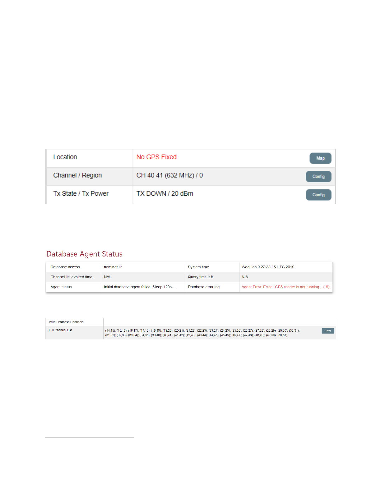
69
Under EN301.598 two types of TVWS device are defined, Type A which is fixed only, and
Type B which is not restricted to fixed operation only. Because the location used for the
database query is updated every 60 seconds the slave may be considered to operate as
either a Type A device (fixed only) or a Type B device (not restricted to fixed only)22.
Confirming GPS Fix
If the radio is GPS enabled, we can check if the radio has a location fix on the Location
section of the Radio Status window on the Monitor tab. For simplicity we use a base station
radio in this example.
In the situation above, the error message “No GPS Fixed” clearly shows the radio has not
achieved a location fix. In addition, since there is no location fix the database query will fail
and we will see the following error in the Database Agent Status window:
In addition there is no valid channel list on the System tab;
The database agent will try to restart every 2 minutes (120 seconds), but will continue to fail
as no GPS fix.
Since there is no successful query and vaild channel list the radio will not turn on and the Tx
State is “DOWN”.
The GPS updates the location displayed on the Monitor Tab every 2 seconds. The GPS
updates the location parameters used for the database query every 3 seconds.
22
See EN 301.598 v2.1.1. Section 4.2.10.1
Page 71
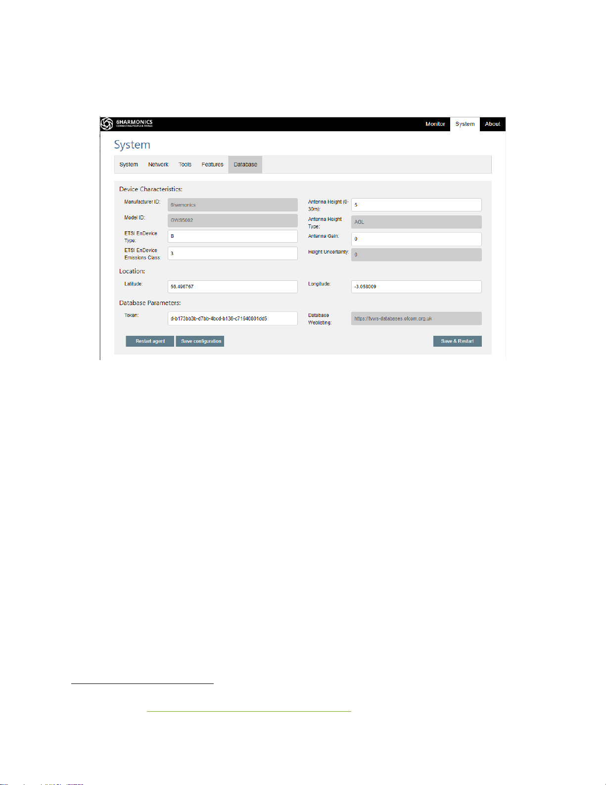
70
Database Tab: Nominet-OFCOM Operation
Below is the database tab for a base station when using the Nominet database for OFCOM:
The fields in dark grey cannot be set by the operator. Location values of Latitude and
Longitude are read every 3 seconds from the GPS. The location cannot be manually entered
on the database tab on the base station, even if the base station radio does not have a GPS
fix. This is because GPS geolocation is a mandatory requirement for a base station (master)
under EN 301.59823.
The Database Weblisting URL24 is the location where the radio will obtain the URL list of
valid databases. Once it has a valid database URL the radio will go to said database URL and
use the token to obtain a channel list. The radio is not permitted to use a database that is
not listed on the regulator Database Weblisting
Device Class is an operator defined parameter and can be 1, 2 or 3. The maximum conducted
power is higher for the radio as a Class 3 device than as a Class 1 device. But the channel
availability and maximum EIRP per channel form the database may be worse for Class 3 than
Class 1. The operator must decide what the optimum configuration should be.
Device Type is an operator defined parameter and can be A or B. A Type A device is for fixed
use only. A Type B device is intended for portable or mobile use. For operation as a Type B
23
See EN 301.598 v2.1.1 Section 4.2.10.2 “A master shall have a horizontal geo-location capability”
24
For OFCOM see https://tvws-databases.ofcom.org.uk/weblist.xml
Page 72

71
device only dedicated antennas specified by 6Harmonics may be used. The use of other
antennas is prohibited25. Operational parameters returned from the database depend upon
device type. A “TVWSD that has geo-location capability shall confirm its location at least
every 60 seconds except while in sleep mode” to be allowed to operate as Type B device26.
The GWS radios update their geo-location every 3 seconds so Type B operation is
permissible.
WARNING: It is the responsibility of the operator/installer to determine if the installation is
Type A or Type B.
Antenna Height (as AGL in metres) & Antenna Gain (in dBi) are also operator defined
parameters. The geolocation location of a client station may be manually entered on the
database tab . But if the GPS is active on the client station and a GPS fix obtained then the
location values will be automatically over written by the GPS every 60 seconds on the client
station database tab.
As explained previously, the database token is inputted during manufacture and the token
lifetime is activated after a number of database queries as determined by the database
provider. The lifetime of the token is determined at equipment ordering and is typically 3 or
5 years.
25
See EN 301.598 v2.1.1 Section 4.2.2 Equipment Types
26
See EN 301.598 v2.1.1 Section 4.2.10 Geo-Location Capability
Page 73

72
We have now explained the key parameters the radio needs to complete a database query:
• The antenna gain
• The antenna height above ground
• The Device Type (A or B)
• The Device Class (1,2 or 3)
• The confirmation that the radio has successfully determined its geolocation to a
sufficient accuracy to allow the database query to succeed.
For the purposes of clarity in the next two sections; Database Operation: Base Station and
Database Operation: Client Station we check the database to obtain the following
information:
• The base station is located at 57.619789, -2.002645
• The base station antenna height is 15m
• The base station transmission EIRP MOP limit for channel 43 is 27dBm
• The base station transmission EIRP MOP limit for channel 23 is 12dBm
Given this information from the database tab input parameters, in conjunction with the
Nominet database planning tool, we now consider the actual EIRP that the base station and
client station may actually transmit at.
Page 74
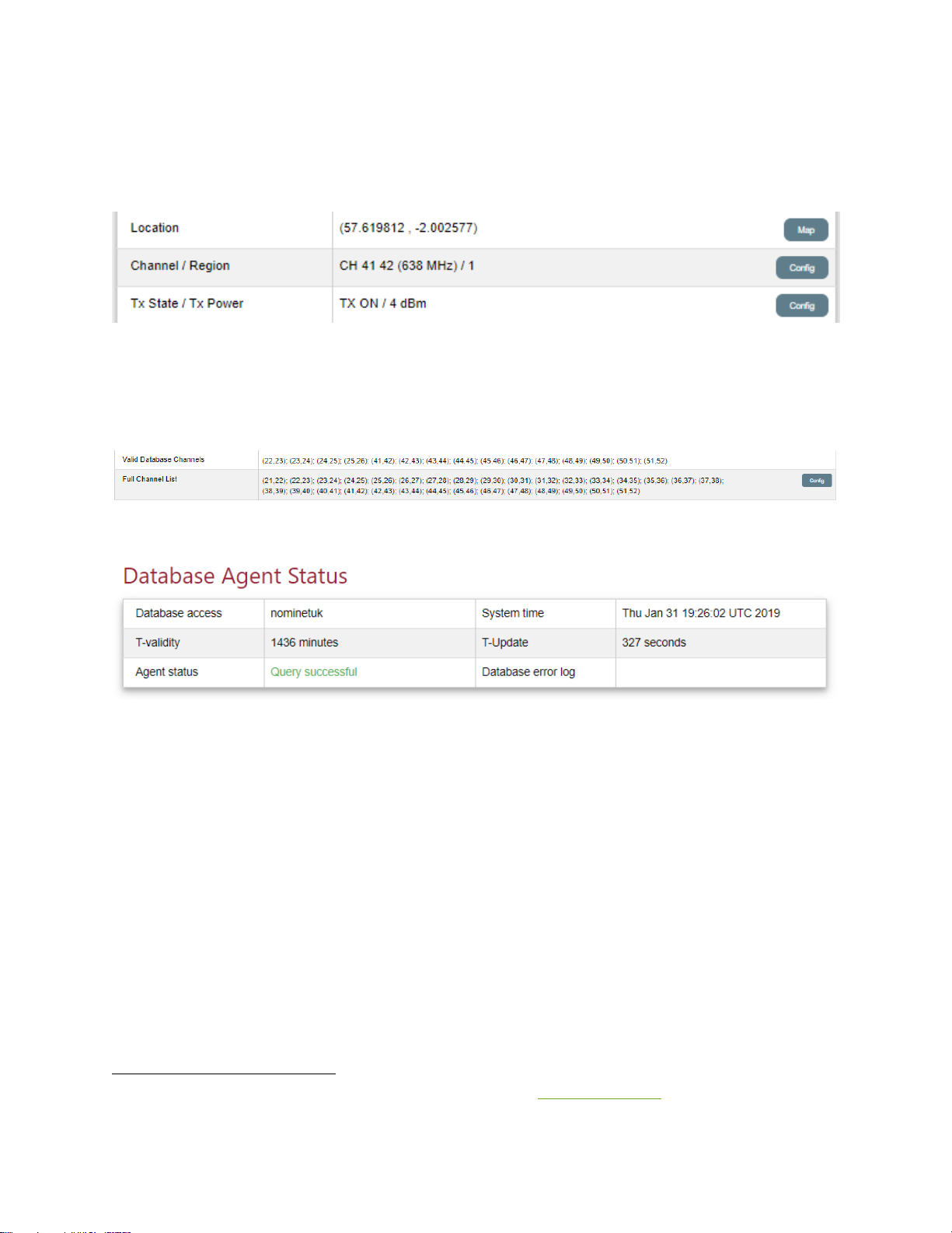
73
Database Operation: Base Station
Once the GPS is able to achieve a fix the Location display will display the actual Latitude and
Longitude values27:
The database agent has attempted a query which was successful. The radio has a valid
channel list and the radio has turned on.
The channel list can be viewed on the System tab:
In addition, we can see the Database Agent Status:
Here T-Validity is time to expiry of the database validity, the time the operational parameters
in the database are valid. The radio also communicates with the database every T-Update to
validate the operational parameters for this radio in this location i.e. the radio channel list
validity. T-Validity and T-Update are defined by the database server28. Different regulatory
domains may have different values for T-Validity and T-Update.
27
Note these are very close locations to the locations used in the preceding sections.
28
For OFCOM, T-Validity is 1440 minutes, T-Update is 15 minutes. N, the weblisting validity is also 1440minutes.
Page 75
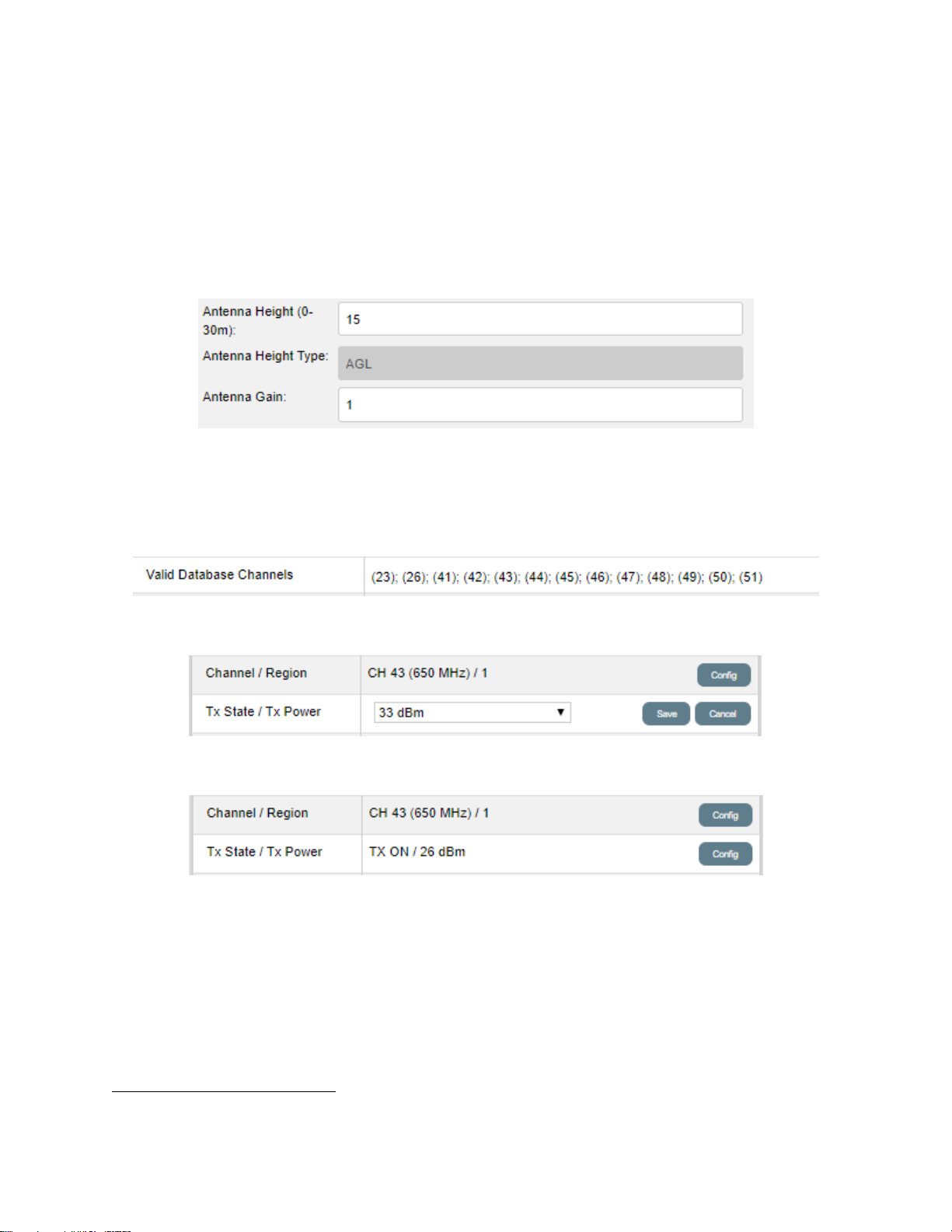
74
Base Station Radio EIRP
We know that the EIRP limit for the base station is 27dBm on Ch 43 and 12dBm on Ch 23.
To understand how the radio operates within regulatory limits for each channel, first set the
bandwidth to MHz and Save.
On the database tab, the antenna height is 15m and the antenna gain29 is 1dBi.
In this case the maximum conducted power for a channel should be 1dB less than the EIRP.
Since we know the EIRP limit for the base station location (MOP) on Channel 43 is 27dBm
then we select channel 43. Ch 43 is a valid channel:
We can test the response by setting the conducted power to 33dBm.
When we try to save the TX power setting of 33dBm we see the following response:
The radio has limited the conducted power to 26dBm and since we specified 1dBi of antenna
gain and the EIRP limit for channel 43 is 27dBm, then the EIRP maximum value specified by
the database.
Similarly, for channel 23 the EIRP maximum for the base station and with an 1dBi antenna
the conducted power maximum is 12dBm.
29
Antenna gain assumes inclusion of any cable losses between the radio and the antenna.
Page 76
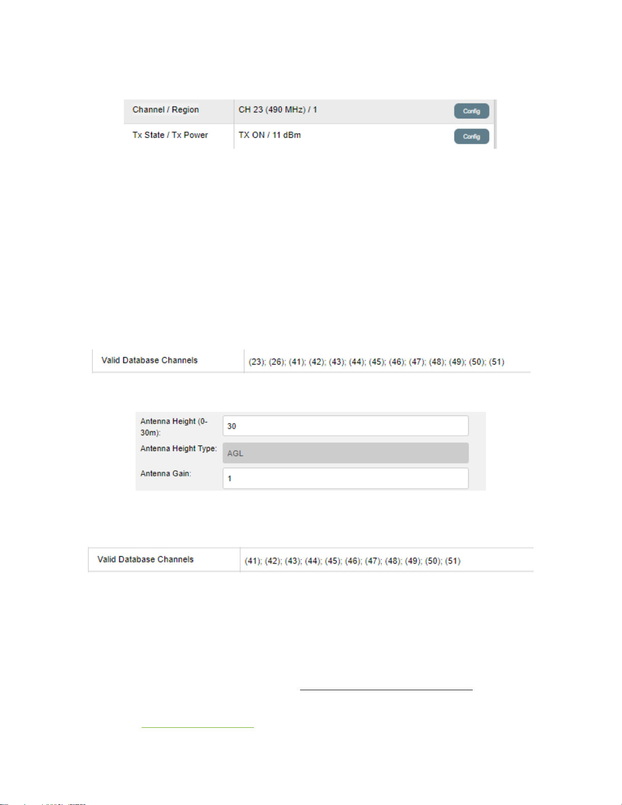
75
Again, we can test the radio response by setting the conducted power to 30dBm.
We can see that the radio software will not allow the base station radio to operate at an
EIRP value that exceeds the combined value of the conducted power and the antenna gain.
An incorrect entry of the antenna gain will impact the allowed conducted power.
Because the radio is GPS geolocated, the channel list and associated EIRP are set by the
database and cannot be overridden. In some locations, the EIRP limits can be quite sensitive
to location so the operator must validate the expected EIRP for a channel as above.
Finally, we consider the impact of changing the antenna height on the valid channel list:
With 15m antenna height we have the following channel list:
We change the antenna height on the database tab, Save & Restart.
Check the valid channel list on the System Tab and we see Channels 23 and 26 are no longer
available.
WARNING: The channel list on the base station (master) is restricted to channels that have
both a valid MOP and a valid GOP. This is because the client station must first connect to
the base station using a GOP channel. Unless a GOP channel is also available for a client
then the master cannot connect to a client. There is no point allowing the base station to
transmit if no client can transmit on a valid GOP. Consequently, usable channels on the
master are restricted to channels that have both a valid MOP and a valid GOP. Repeat: if
there is no GOP the channel will not appear in the base station channel list. This issue is
addressed in SOP Direct Operation.
Page 77
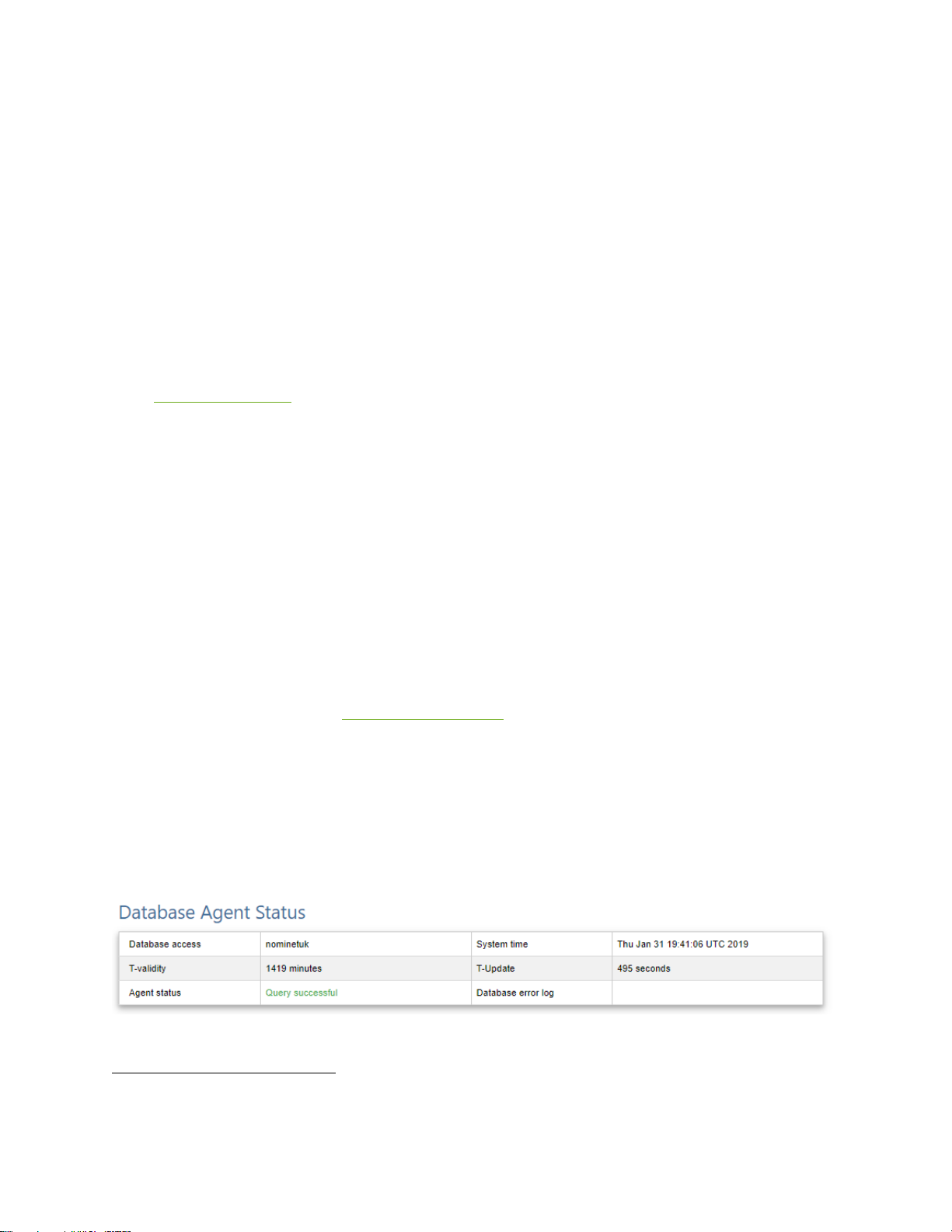
76
Database Operation: Client Station
Manual Geolocation
Similar to operation under FCC, the client station radio will scan until it sees a signal from a
base station radio, and then it will try to connect. Assuming the IP and SSID configuration
allow the client radio to connect to the base station and the client radio will query the base
station for GOPs and then the database for SOPs. However, for this two-step process to
successfully complete, the base station and a client station must use a channel that has valid
MOPs for the base station and GOPs for the client station first. The data exchange30 is not
allowed using a channel that is only valid as an SOP channel at the client. Importantly, as we
have shown previously the EIRP values for SOPs are usually higher than for GOPs. This
creates the possibility that a client radio cannot connect to a base station using GOPs, but it
could with SOPs. In that case, the client may only receive SOP data t using another GOP
channel.
Even if the client station radio has downloaded both GOP and SOP channel lists, operation is
further restricted depending on whether the client is GPS geolocation or not. If the location
of the client is manually defined then the client station can only use GOPs, i.e. the GOP
channel availability and the EIRP limits as described previously.
GPS Geolocation
If the client station does not have a GPS fix it may use a manually entered location and will
be restricted to GOP only. As explained previously, if the client station radio is able to
determine its’ location via a GPS it may also choose between the best of GOP or SOP channel
availability and associated EIRP limits.
Once a GOP based connection has been established to a base station, the client station will
then obtain the SOP channels. Depending on location, channels will appear in the client
station channel list31.
30
A data exchange requires the client station to transmit. Until it has downloaded the SOP channel
31
It is unlikely an operator will observe this process as it is too fast.
Page 78
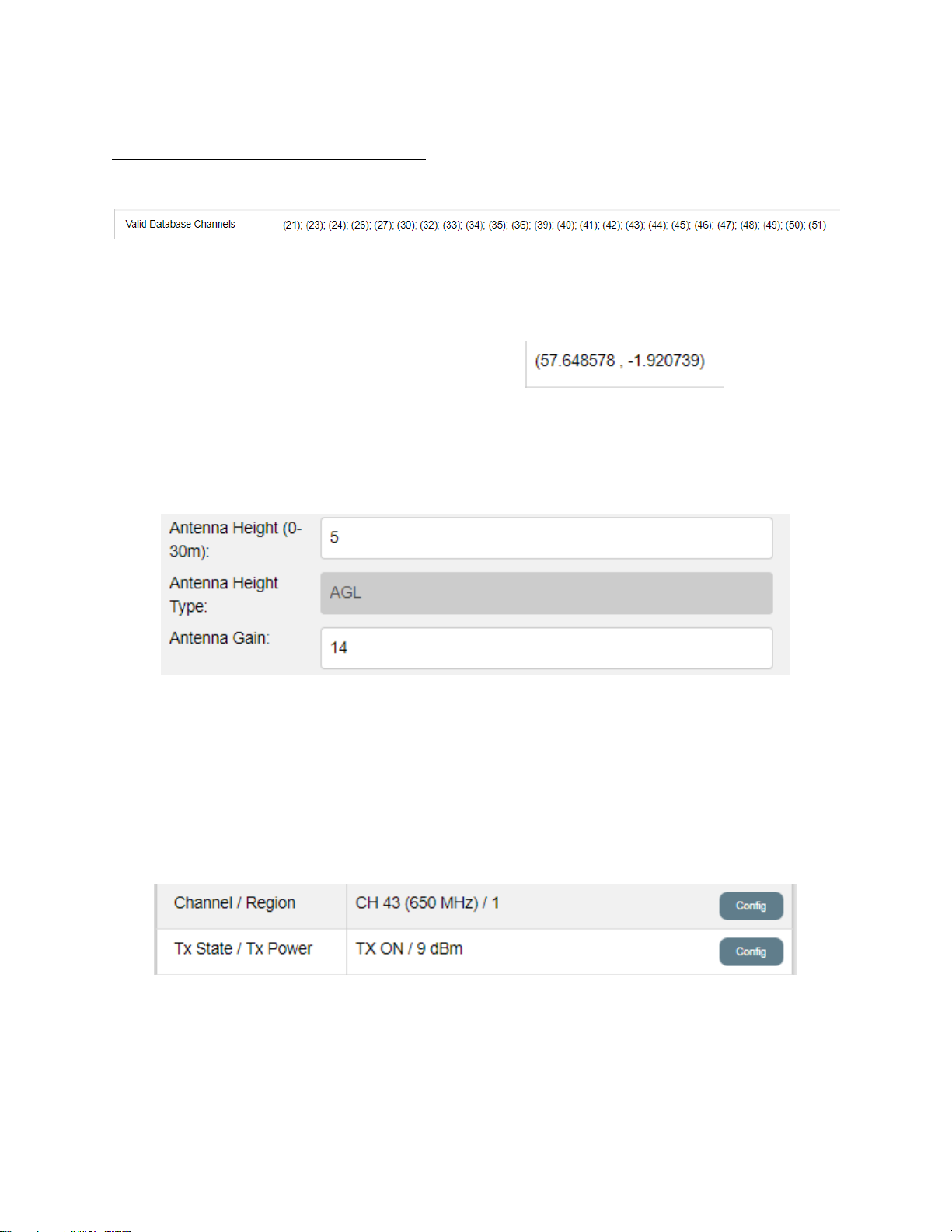
77
The client station radio now has an updated channel list, for each channel the radio may use
the higher EIRP limit of the GOP or SOP. In this case the client station channel list appears
as follows on the System Tab:
Client Station Radio EIRP
We can now check that the radio is operating within the EIRP limit per channel, either GOP
or SOP.
The client station is located at 56.648578, -1.920739
On the database tab of the client radio we set the antenna height to 5m and the antenna
gain to 14dBi.
We choose 14dBi antenna gain purely for purposes of explanation.
Click on Save & Restart.
The GOP EIRP limit for Channel 43 is 20dBm.
The SOP EIRP limit for Channel 43 is 35dBm.
Immediately after restarting the database agent we try to set the conducted to 30dBm and
the radio responds as follows:
The client radio is only able to use the GOP EIRP limit of 23dBm (9dBm conducted plus 14dBi
antenna gain).
The client radio has not yet had enough time to pull an SOP list from the database, so the
client station operation is limited to GOP EIRP limits. Wait 2 minutes.
Page 79
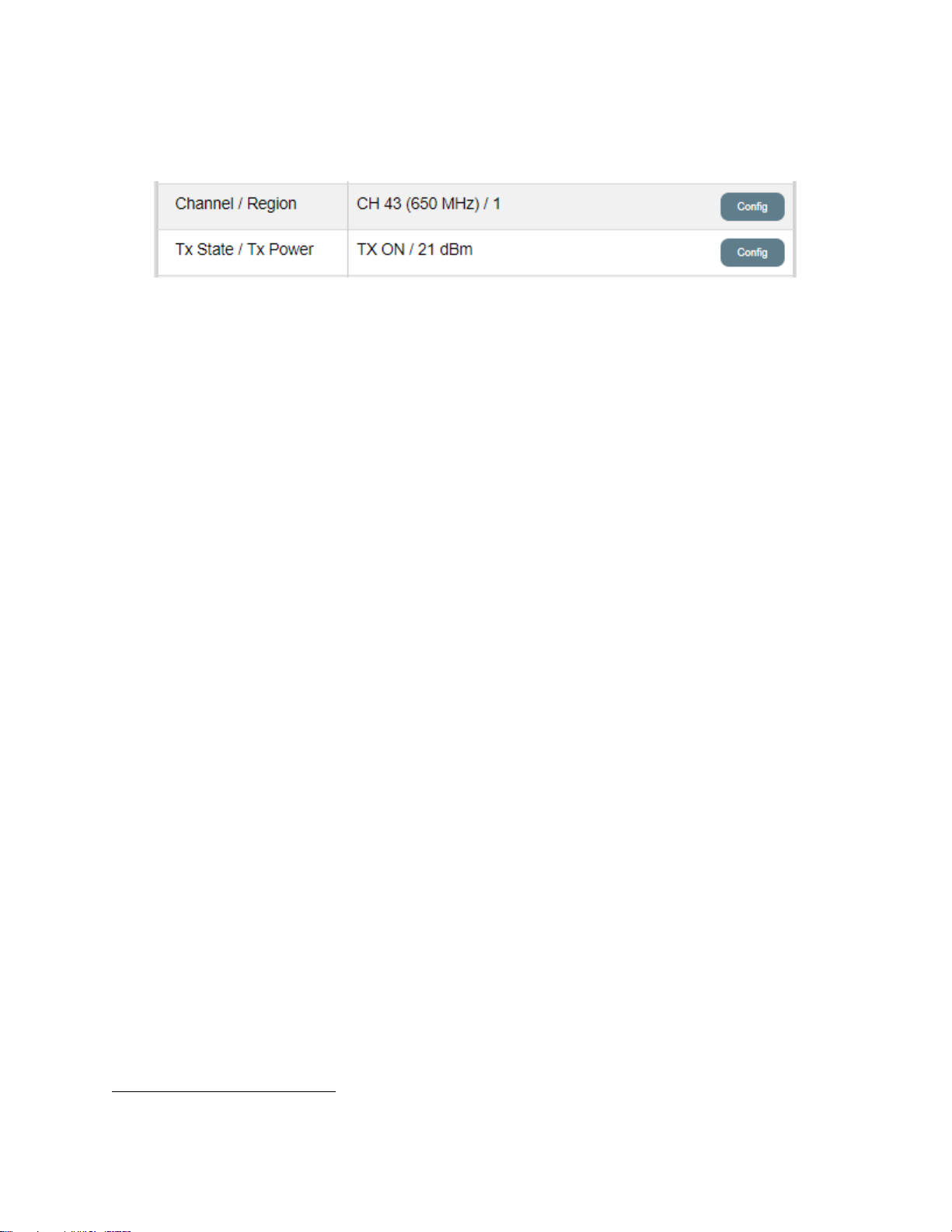
78
After >2 minutes the client radio should have pulled a new SOP list from the database32 and
we can try again to set the conducted power to 30dBm, the radio responds as follows:
The client radio is now able to use the SOP EIRP limit of 35dBm (21dBm conducted plus 14dBi
antenna gain) for channel 43.
In the event of a loss of power at the client radio, on reboot the radio must follow the initial
connection process using GOPs before it can use SOPs to be regulatory compliant. If the
client radio cannot connect using GOPs it will not download SOPs and will continue to scan.
If the GPS on the client station loses the location fix, the EIRP limit will be restricted to the
GOP limit.
SOP Direct Operation
RESERVED
32
Restarting the database agent means the client radio pulls a new SOP list that overwrites the previous list.
Page 80
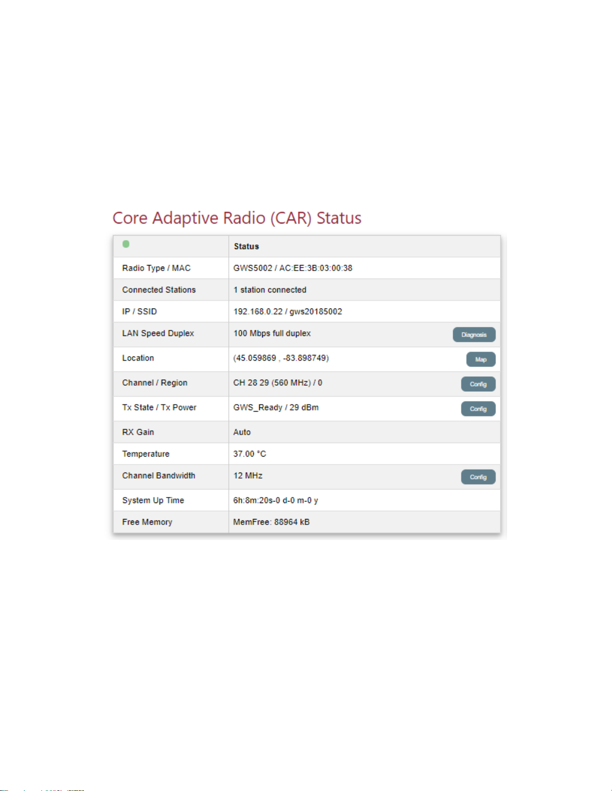
79
GUI Details
In this section we provide a detailed description of the various Tabs, Sections & Windows of
the GUI.
Monitor Tab
Radio Status
Core Adaptive Radio (CAR) means this radio is a base station. If the display shows Edge
Adaptive Radio (EAR), the radio is a client station.
Radio Type is the model number, in this case it is a GWS5002.
MAC Address is the MAC address of the radio. As mentioned previously, the radio needs
internet access to get to a database. Some networks have MAC address filtering, and if that
is the case, the operator needs the MAC address to ensure the radio can access the internet.
Connected Stations, as a base station multiple client stations can connect to this base
station in a point-to-multipoint architecture.
Page 81
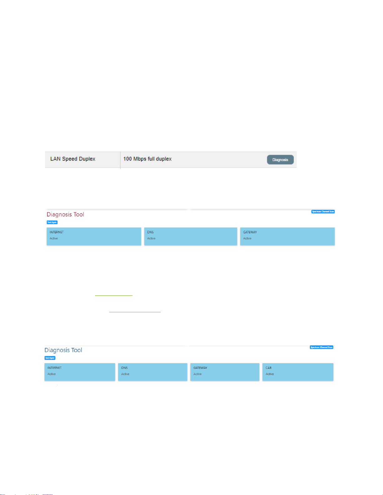
80
IP / SSID is the IP address and SSID of the radio.
LAN Speed Duplex shows the status of the LAN port on the GWs radio. If there is no data
connection to the data side of a client station it will show “Ethernet down”. This status
setting is useful to see if there are any issues with the data connection on the radio. If a port
on a switch that is connected to a base station has become faulty, say 100M half-duplex
versus 100M full-duplex the display will indicate this fault. The LAN port of the GWS radio is
always in Auto negotiation and displays whatever the status is.
LAN Diagnosis button.
This button is to the right of the LAN Speed Duplex display.
Base Station: Click on the diagnosis button. The LAN Diagnosis tool window appears.
Blue=success, yellow =failure.
Internet means a ping to an internet address, the default is Google.
DNS means the DNS setting is valid.
Gateway means the Gateway setting is valid.
Client Station: similarly click on the diagnosis button, and the LAN Diagnosis tool window
appears.
CAR active means that the client station is able to ping the base station successfully. Before
attempting to analyze any issues with throughput or database connectivity, the user should
check that the Diagnosis Tool shows all network requirements are active.
Page 82
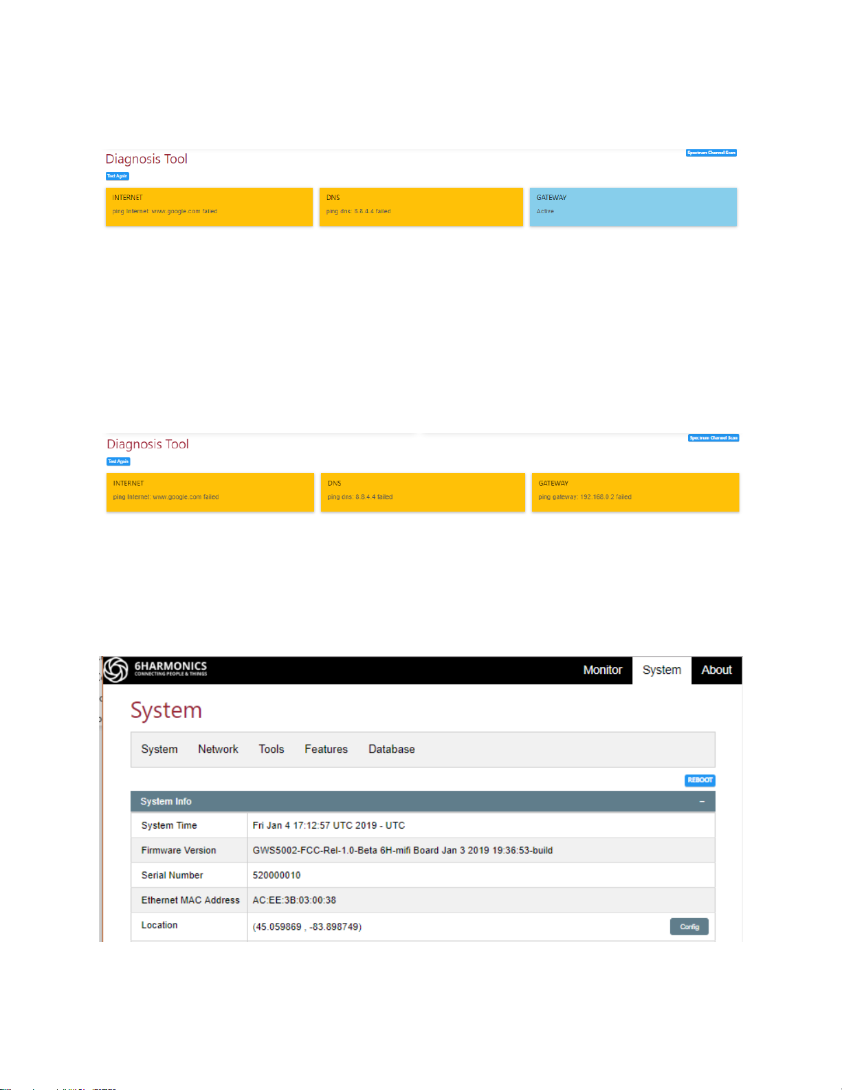
81
If for example, there is a break in internet backhaul to a base station then the INTERNET
display will go yellow.
Because the internet connection is lost, and this radio is using a public DNS then the DNS
display also goes yellow. If the DNS was private, it would stay blue.
The GATEWAY stays blue because the radio can still see the gateway to the internet but
there is no internet access behind the gateway.
If there was internet access, but the gateway setting on the radio was incorrect we would
see:
Here you can see that the radio attempted to use 192.168.0.2 as a gateway IP address, which
is incorrect.
Location is the latitude and longitude in decimal degrees. These values are used on the map.
Depending on the radio model, the location may be user defined on the System tab:
Page 83

82
Click on Config button to enter the radio latitude and longitude. Six decimals should be used
to ensure location accuracy.
WARNING: if the values are incorrect the map display will be erroneous. Check the location
using the Map feature.
If the radio is equipped with GPS geolocation, the latitude and longitude are determined by
the GPS and there is no user defined location input field.
Page 84
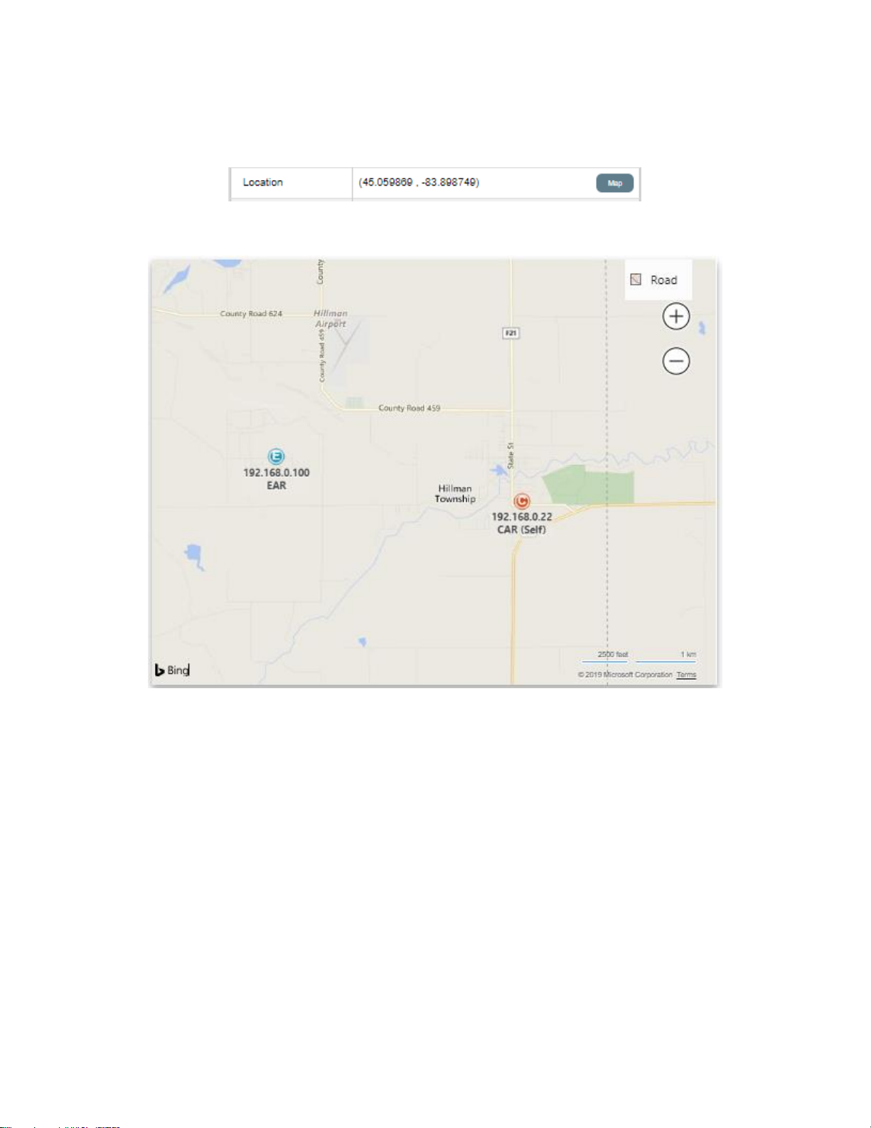
83
Map
To the right of the Location field is the Map button
Clicking on this button will toggle the display / non-display of the map.
The map is not on the radio, it is on the PC being used to access the radio. It will only appear
if the PC has access to the internet. The PC uses the Location values to display the radio
locations.
• Red is a base station.
• Blue is a client station.
The IP addresses are also displayed.
“Self” is the radio GUI that the PC is logged into.
The map format and zoom can be changed using the map tools in the top right of the
window.
Page 85
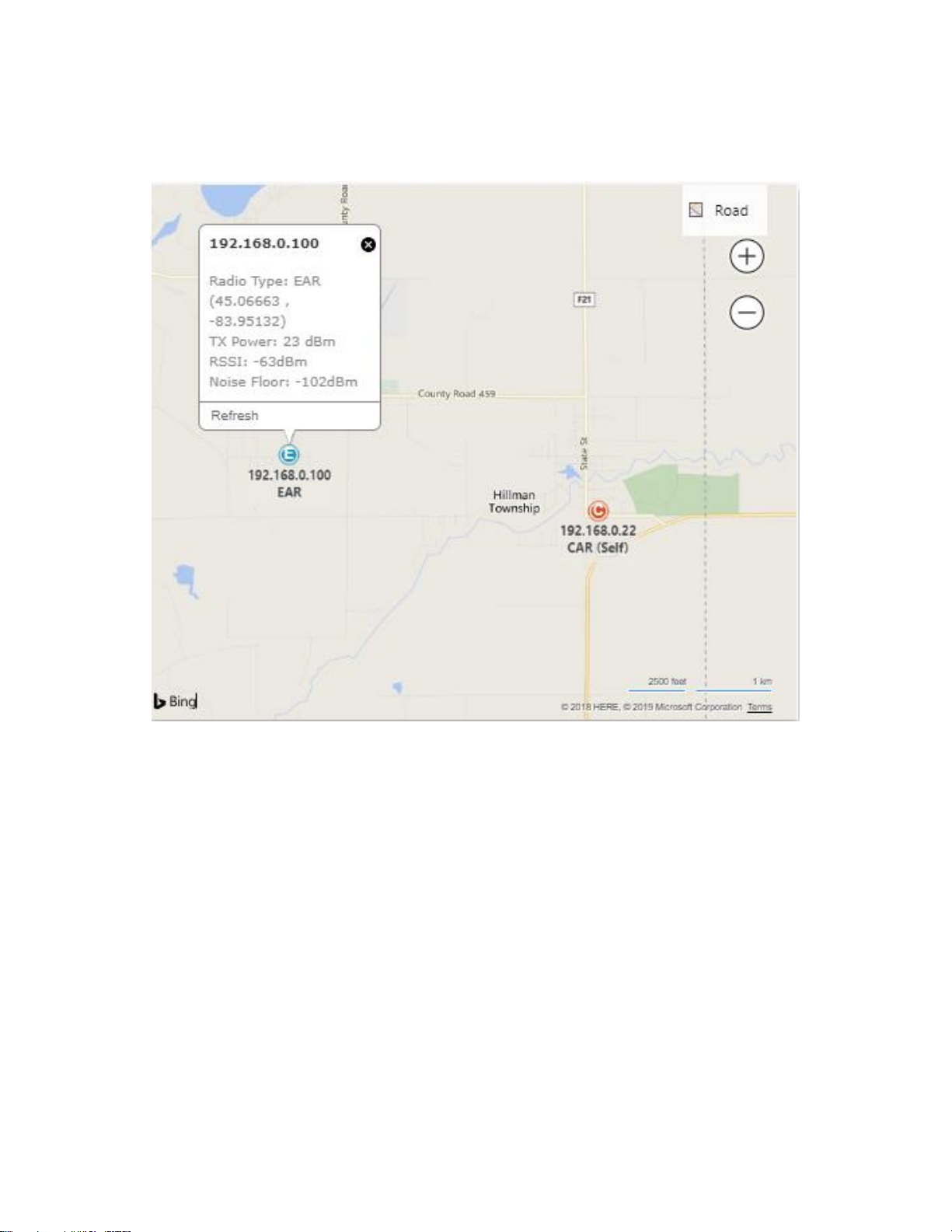
84
In addition, clicking on the blue client station icons will display key parameters of the client
station radio. See below.
This tool enables the user to see:
• the overall network architecture
• the range of the clients from the base station
• the azimuth of the client from the base station and if the client station lies within the
azimuth range of the base station antenna
• the signals at various client stations-are there clusters of noise / interference? Do the
signal strengths make sense?
• if obstructions or tree cover are an issue by using the satellite map mode.
Page 86
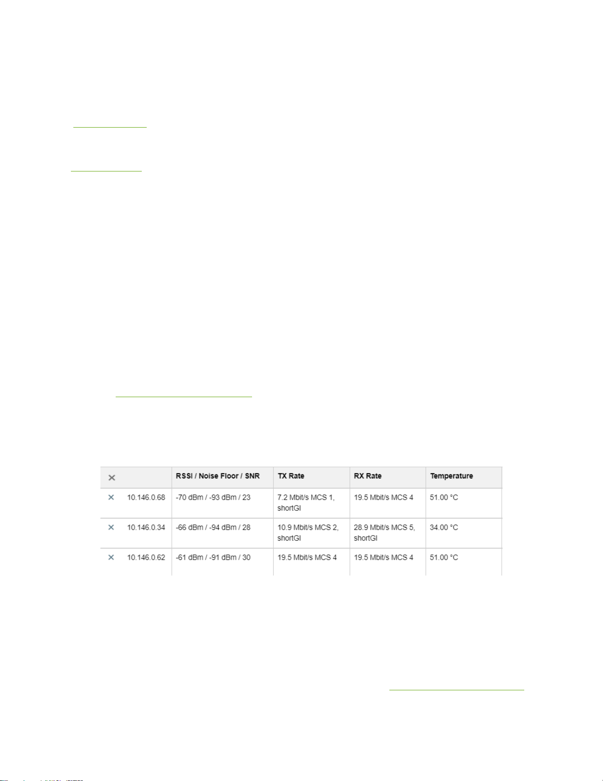
85
Channel / Region (Channel plan) refers to the channel the radio is operating on. The pulldown menu is used to set the channel number manually. Don’t forget to save.
Channel plan 0 (6MHz) is used in the Americas (most countries), South Korea, Taiwan,
Philippines and Japan.
Channel plan 1 (8MHz) is used in the United Kingdom, Ireland, Hong Kong, Macau, Falkland
Islands, Western Europe, Eastern Europe, Greenland, most countries in Asia and Africa, most
of Oceania, the former Soviet Union and French overseas territories.
TX State / Tx Power: if the TX state shows TX ON or GWS_Ready then the conducted
transmit power can be selected from the pull-down menu (don’t forget to save). If the radio
is manual and the channel list is not specified by a database, then the maximum conducted
power will be 33dBm (2W). If the radio does use a database to obtain a channel list, then the
database will also determine the maximum EIRP allowed at the Location and at the antenna
AGL. The radio will automatically limit the conducted power to ensure the radio operates
within the parameters defined by the database. It is the operator’s responsibility to ensure
antenna AGL and antenna gain are correct.
RX Gain: see Automatic Gain Control.
Temperature: The GWS radio has an internal temperature sensor. This sensor is only
accurate to 5C. Any operating temperature comparisons between radios in the same
location should recognize the accuracy of the value.
In the example above, 10.146.0.68 and 10.146.0.62 indicate 51C and 10.146.0.34 indicates 34C.
10.146.0.34 is outdoor, the others are indoor and as such the temperature values make
sense.
Channel Bandwidth: Most GWS radios provide a selectable bandwidth which are typically
multiples of the TV channel bandwidth e.g. 6-12-18-24MHz. This allows an operator to
compromise between throughput and range, depending on the performance requirements
Page 87

86
of the link. The bandwidth can be set using the pull-down menu (don’t forget to save). Some
GWS radios have narrower custom bandwidths33 which are used for extended range links
where range is more important than throughput.
System Up Time: indicates the time that the GWS radio has been powered up. In conjunction
with a client station System Up Time and the Radio Link Uptime timers, a base station
System Up Time can be used to indicate power outages or interference that has broken the
link. For example, if both the client and the base station have been “Up” for a week but the
Radio Link Uptime is a few hours then likely interference or noise broke the link for a few
seconds and then the link was re-established. Issues such as base station power supply
stability, residential power outages, noise or interference hot spots can be identified using
the System Up Time and Radio Link Uptime timers.
Free Memory shows the GWS radio free memory remaining. This may change after a
firmware upgrade.
33
The minimum custom modulation bandwidth is 1MHz. The maximum is 32MHz.
Page 88
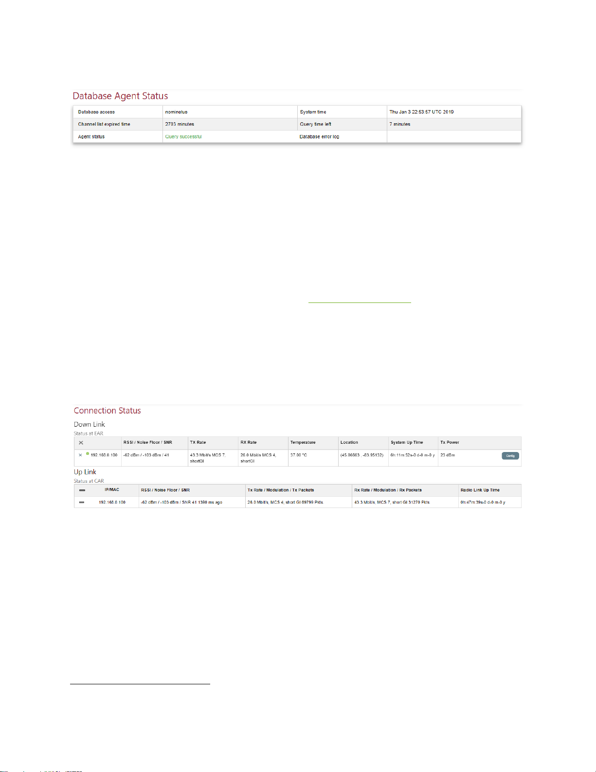
87
Database Agent Status
Database access is the database provider.
Channel list expired time is the time the radio will continue to operate with a valid channel
list. It is the time (in minutes) between the System Time and when the Channel List will
expire on the database. On the version for EN 301.598 this field is labelled T-Validity34.
Agent status shows status during or after a database query.
System time is needed to ensure the database query exchange is successful as the exchange
is time stamped. The GWS radio needs access to NTP for System Time to ensure success.
Query time left is the count down time to the next database query. Typically, the query
occurs every 15 minutes. On the version for EN 301.598 this field is labelled T-Update.
Database error log in the event of database query errors, error messages appear here.
Connection Status: Base Station
On the Down Link window, the TX Rate is the transmit from the client station to the base
station (MCS 7).
On the Up Link window, the TX Rate is the transmit from the base station to the client
station (MCS 4).
On the Down Link window, the RX Rate is the received rate from the base station at the
client station (MCS 4). On the Up Link window, the RX Rate is the received rate from the
client station at the base station (MCS 7).
34
EN301.598 uses T-Validity and T-Update as specific parameters as part of the database query process.
Page 89
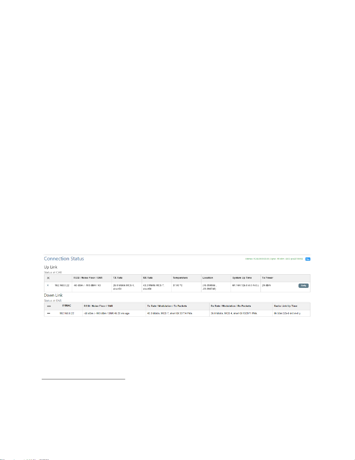
88
The MCS values of an RX (say client) and a TX (say base station) should be the same, but
they may also fluctuate with time due to traffic flows.
Status at EAR=Status at Client Station.
Status at CAR=Status at Base Station.
In the TX power box of the Down Link section if you click on Config the user can set the
transmit power of the client station, i.e. you can set the transmit power of a client station
radio form the base station GUI without logging into the client station radio.
Radio Link Up Time refers to the time the radio link has been passing data.
NOTE: If the link is broken for more than 1 second the clock will restart. If the link is broken
for >5 minutes the client will commence to scan for a base station.35
IP / MAC if clicked can be used to toggle the display between IP address and MAC address of
all the connected radios.
Tx Packets and Rx Packets indicates the packet traffic. It is useful to discriminate uplink or
downlink centric traffic at each client station.
Modulation, maximum throughput occurs when MCS 7, short GI36 is displayed.
Connection Status: Client Station
At the client station the status windows are reversed but Up Link and Downlink retain the
same meaning.
RX at base station is MCS 7 & RX at client station is MCS 4.
35
Networks typically use a ping test as a heartbeat to see if a connection is “up” and to determine network
reliability e.g. 98.7% uptime. Such pings are typically every 30-120 seconds, a time interval much longer than 1
second. Expect a discrepancy between the Radio Up Link timer and the period between loss of network ping
to a client radio.
36
Short GI = short guard interval
Page 90
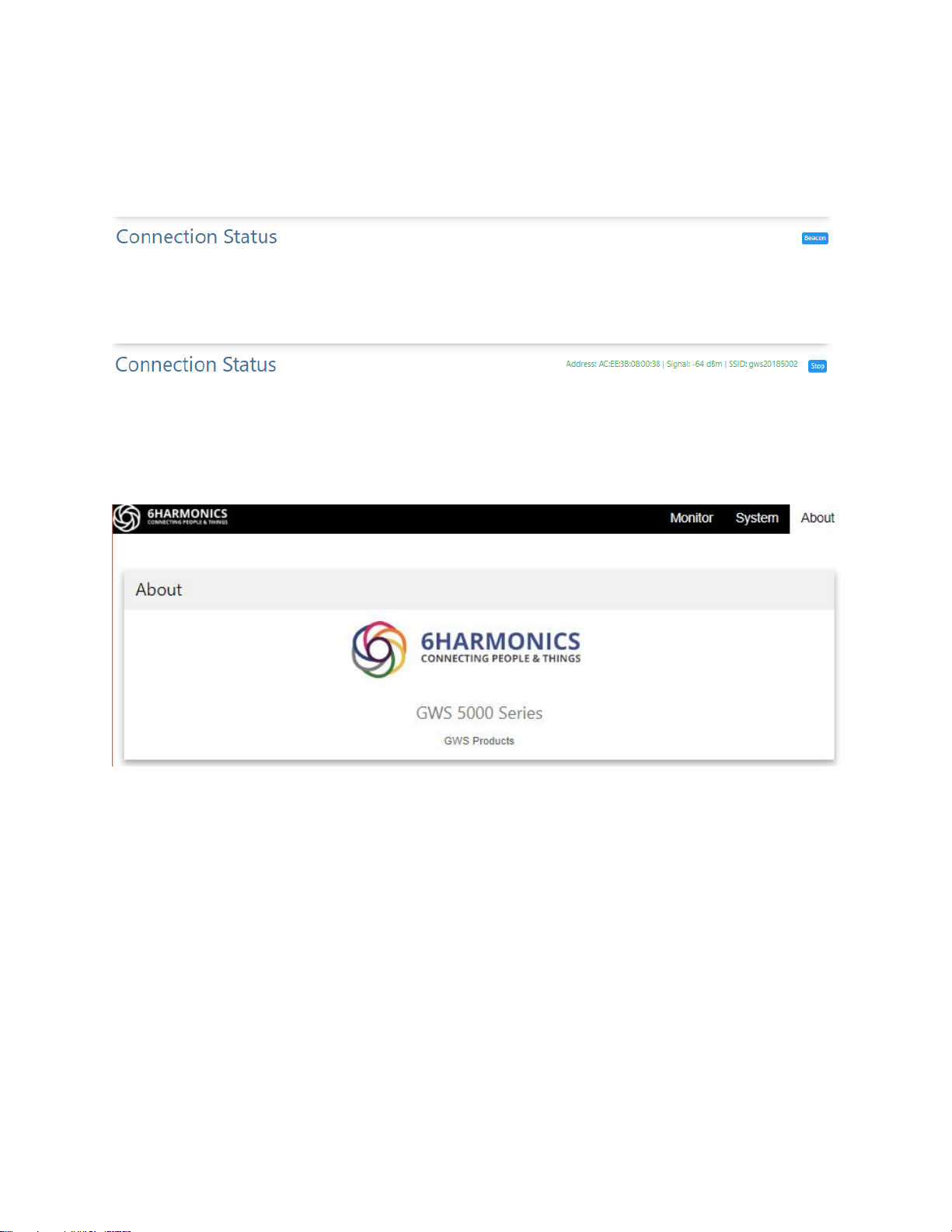
89
Beacon button
On the client radio there is a Beacon button on the right side of the Connection Status
window.
Click on the button; the MAC address of the base station, the unprocessed signal strength at
the client station, and the SSID of the base station will be displayed.
The beacon signal display can be used to monitor the stability of the received signal at the
client station radio.
About Tab
The about tab shows general information about the radio.
Page 91
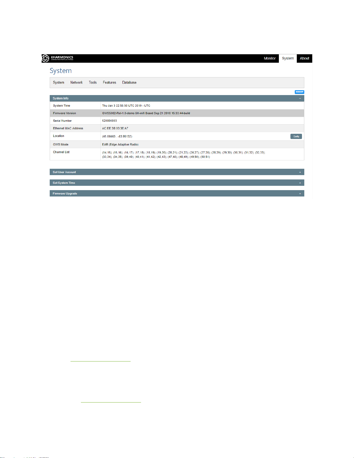
90
System Tab
On the system tab there are 4 additional sub-tabs: Network, Tools, Features and Database (if
implemented).
On the System Tab page, the following are displayed in the System tab window.
REBOOT button. This button located to the right on the window is used to reboot the radio.
When this process is initiated the firmware will be reloaded from the flash memory and all
processes will re-initialized.
System Time shows the UTC time or the time for time zone the radio is located in.
Firmware Version displays the current firmware version on the GWS radio.
Serial Number which is required for warranty repairs and database query. The serial number
is linked to a specific database token. A mismatch will cause a database query to fail.
MAC Address, provided to ensure no MAC address filtering issues.
Location, described previously.
GWS Mode, should be CAR for a base station and EAR for client station. The loads must
match the hardware.
Channel List, described previously.
Page 92
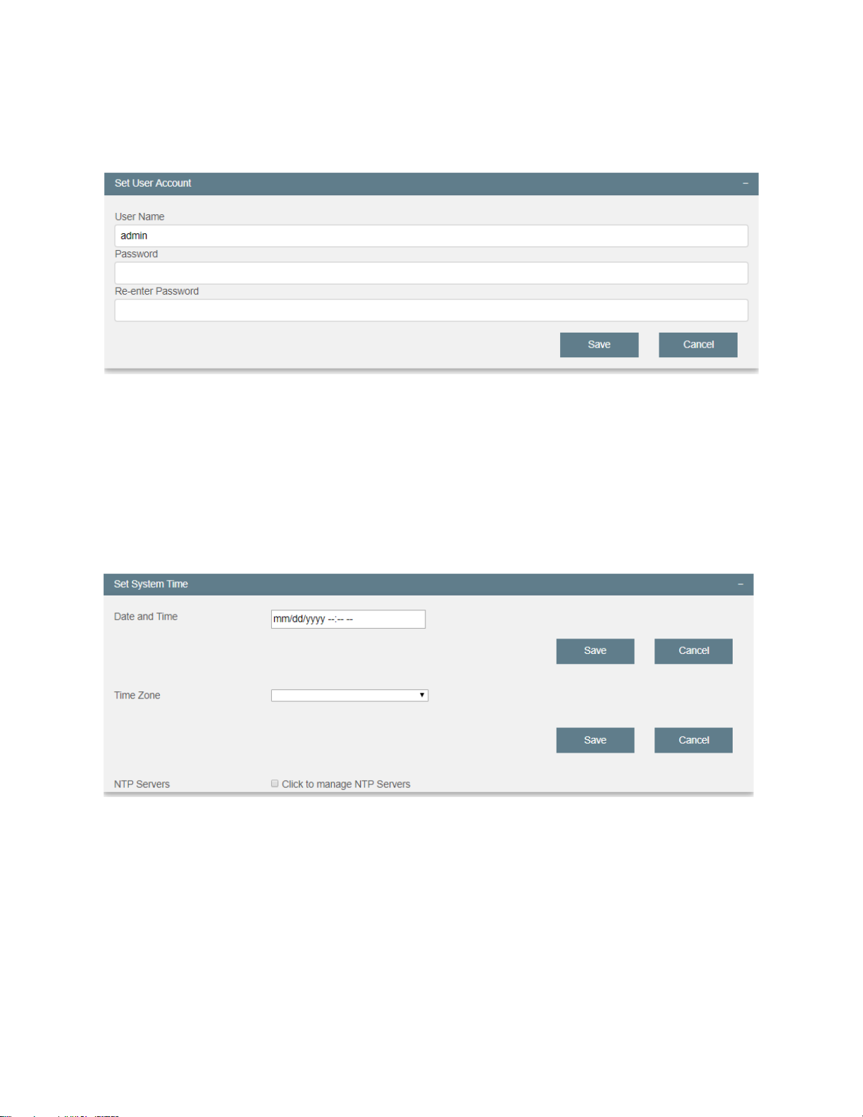
91
Set User Account
Click on Set User Account and the window below appears:
Enter a new username, password and password confirmation. Click on Save.
Click on the minus sign (top right) to close the window.
Set System Time
In order to complete a database query, the GWS radios need to set System Time.
Click on Set System Time and the window below appears:
Page 93
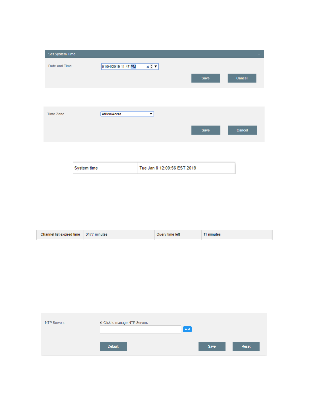
92
Enter the date & time and save. Care with format.
Select the time zone from the pull-down menu.
The System Time on the monitor page should now display these values.
WARNING: If the System Time is set incorrectly then the “Channel List expired time”
display window will be incorrect. This is because the Channel List expired time counts
down from the absolute time (in minutes) between the current System Time and the time
stamped last database query. Query time left is the relative time as a countdown timer to
the next database query.
WARNING: The GWS radio does not have an internal battery. If the radio is power cycled it
will lose the System Time setting.
To mitigate the loss of System Time during a power cycle or setting an erroneous System
Time manually the GWS radio can use a public (WAN) or private (LAN) NTP server.
If either LAN/WAN has access to an NTP server, “Click to manage NTP servers” box and the
window below appears:
Page 94
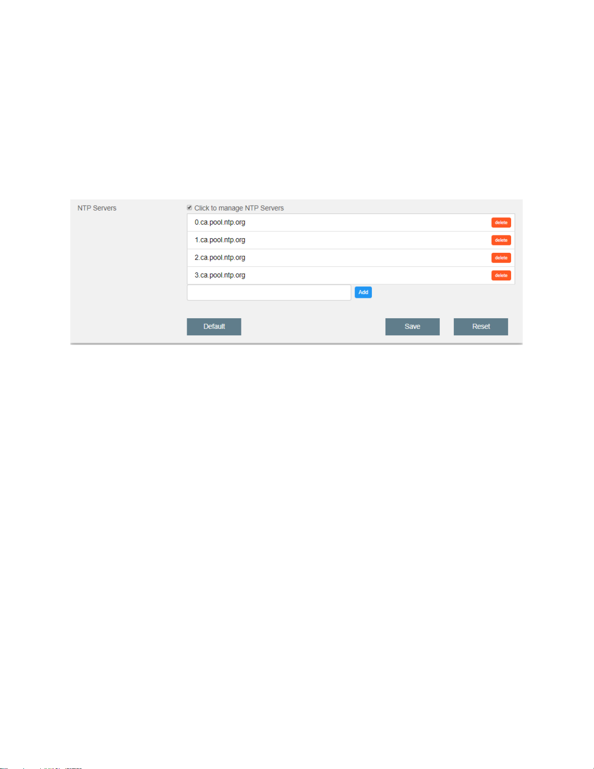
93
The user may now enter an external or internal NTP server. Click on Save and the radio will
now use this NTP server to get System Time. The user must ensure the GWS radio has the
appropriate network access to a specific NTP server.
Install a Default External NTP Server
Click on Default to view and edit the Default NTP server list. Clicking on Default will load the
following external (public) NTP Server list.
If required, click on the Add button and enter the web address of the NTP server. It will
appear in the NTP server list.
NTP servers, either public or private, maybe deleted using the delete button. The radio will
use the NTP servers in the list in order of the list to get System Time.
Once the list is correct, click on Save.
WARNING: If the radio does not have a valid System Time the database query may fail, and
the radio will not operate. If the LAN / WAN does not allow access to the NTP server in the
above list, the database query may fail.
TIP: Always try to use an NTP server for System Time.
Page 95
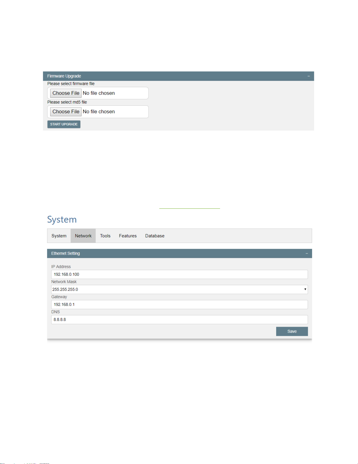
94
Firmware Upgrade
Click on the Firmware Upgrade tab and the following window appears:
When a firmware upgrade is required users will be provided with upgrade files and specific
instructions.
WARNING: Do not attempt to upgrade without specific instructions and files from
6Harmonics.
Network Tab
The Ethernet Setting window has been explained previously.
Page 96
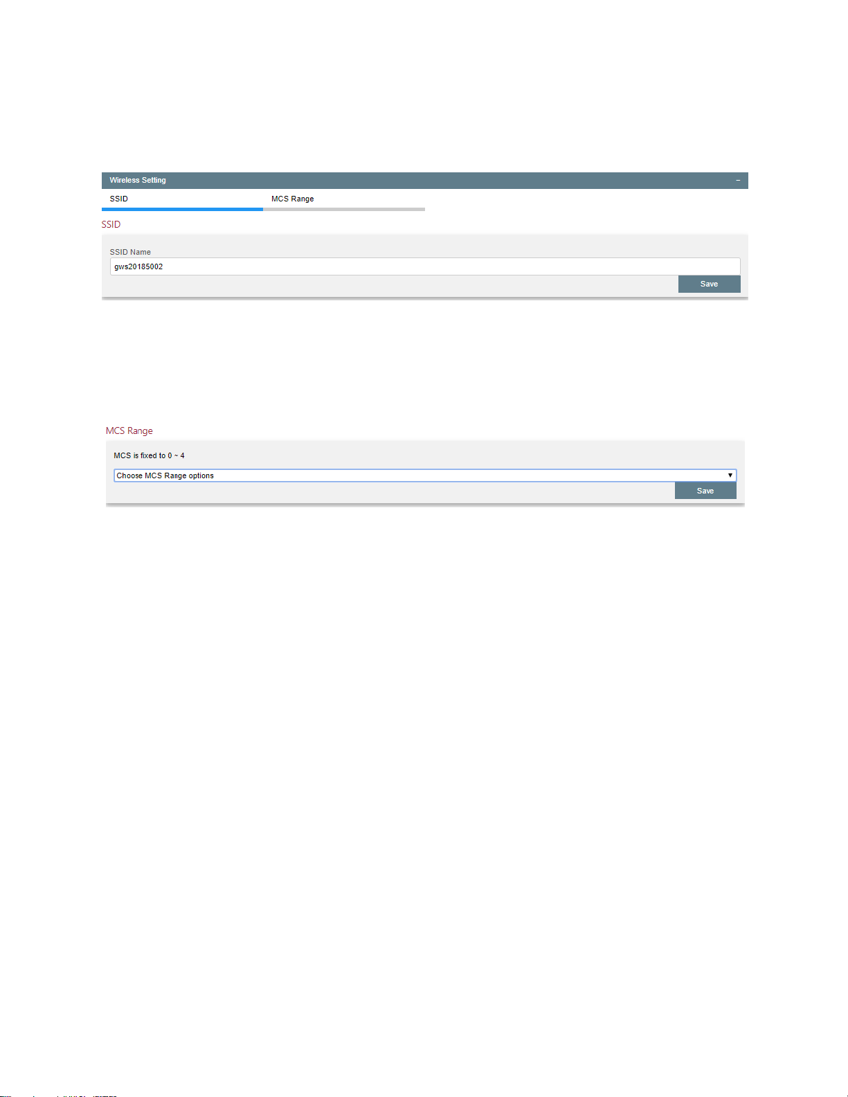
95
Wireless Settings
Click on Wireless Settings and the window below appears:
Input the SSID value and Save. Do not use spaces.
MCS Range
Click on MCS Range and the window below appears:
Use the pull-down menu to choose the MCS range and Save.
The purpose of this setting is to ensure link stability if the RF environment is unstable. If the
RF environment widely fluctuates between being able to support say MCS 7 and MCS 3
because of intermittent interference or noise, it would make sense to set the MCS range to
0-4. This way the radio is not trying to stabilize the channel state algorithm to values it
cannot reliably sustain.
Page 97
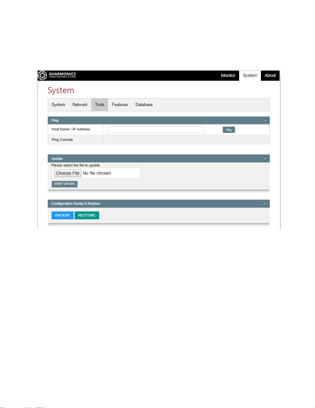
96
Tools Tab
The Tools tab consists of three windows, the Ping Tool, the Update tool and Configuration &
Restore. Click on the respective bar to display.
Page 98
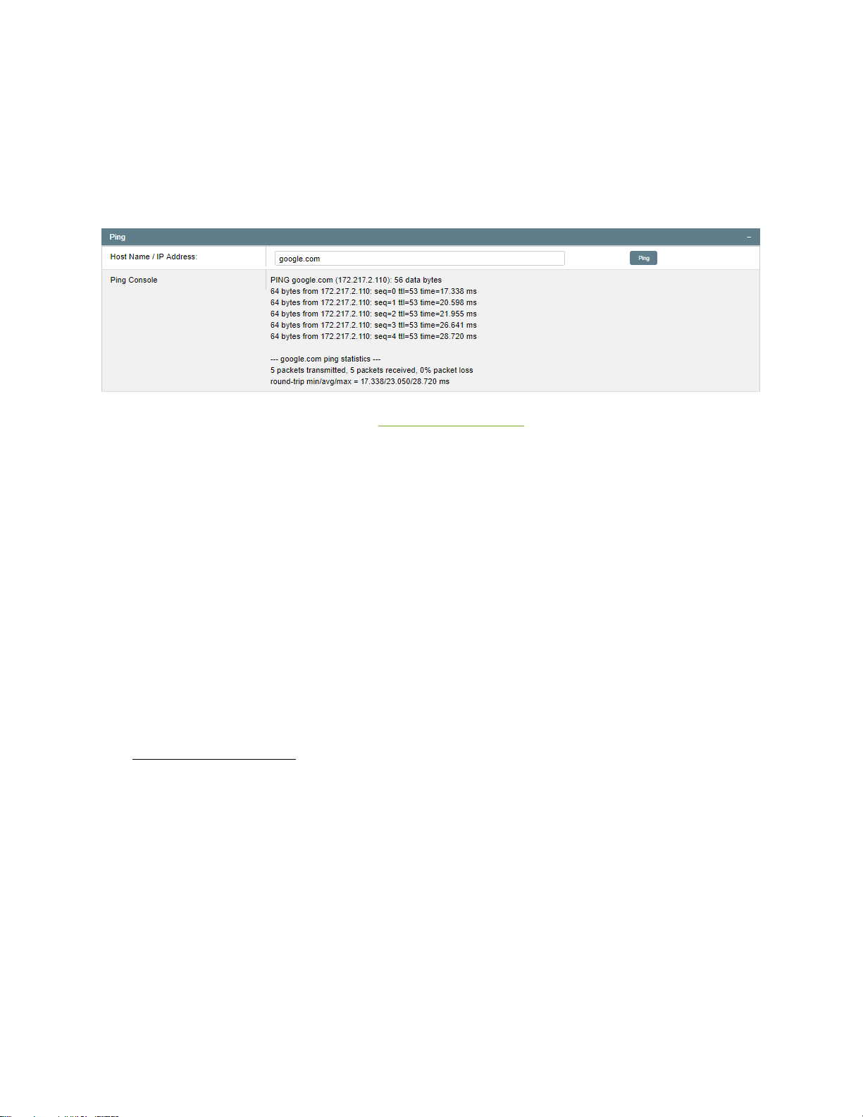
97
Ping Tool
The purpose of the Ping Tool is to determine if any particular segments of the network are
causing excessive latentcy or packet loss. This allows an operator to identify the source of
problems. The ping tool can use a web address or an IP address.
Knowing the IP network configuration discussed previously we can try the following ping
tests:
• Client to Google (as above)
• Client to base station
• Client to gateway
• Base station to Google
• Base station to gateway.
You may also be able, if network equipment allows, to ping Google from the gateway. All
the ping tests should be additive and self-consistent. Repeat the test at least three times to
obtain consistent results.
If any single ping test shows packet loss or excessive latentcy, investigate further.
TIP: Before installing a CPE do a ping test from the base station to the allocated IP address
for that CPE. There should be no response. This quick and simple check avoids the risk of
setting an IP address that causes an IP loop.
WARNING: When a base station has multiple clients and traffic is flowing the actual ping
test from a base station to a client station, and vice versa, can vary from 2mseconds to as
much as 20mseconds. This is because WiFi is an on-demand time-slot TDD based protocol
Page 99
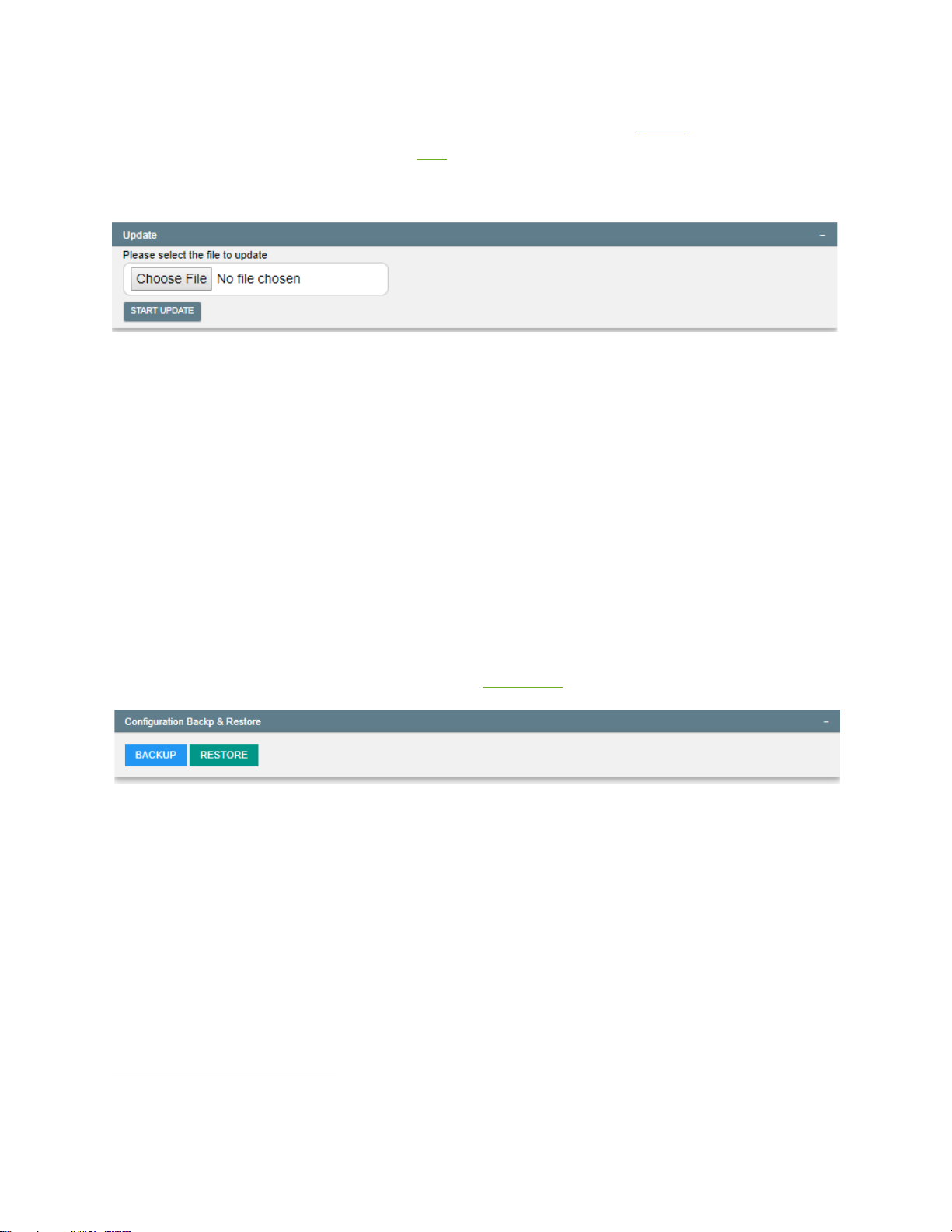
98
and traffic patterns determine access to the transport medium. If TDMA37 is enabled,
expect a change in latentcy. Similarly, ATF38 will also impact the downlink latentcy.
Update
The Update window is used to patch the firmware. When a patch is applied, the firmware
load will NOT change.
When an Update is required users will be provided with update files and specific
instructions.
WARNING: Do not attempt to update without specific instructions and files from
6Harmonics.
Configuration & Restore
Click on the Configuration Backup & Restore bar to display the Configuration Backup &
Restore window.
If the user has lost the IP configuration use the Djinni tool to regain access to the radio.
Backup:
Click on Backup to save the current configuration settings to memory.
Restore:
Click on Restore to install the configuration settings stored in memory.
37
TDMA=time domain medium access, where stations have fixed time slots in a predefined sequence.
38
ATF=airtime fairness, where a station cannot hold access to the medium to the detriment of other stations.
Page 100

99
Features Tab
See Features section.
 Loading...