

Page 1
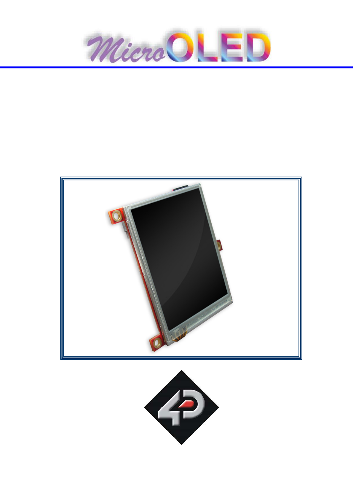
µOLED-3202X-P1
USERS MANUAL
(4DGL Platform Only)
Revision 1.0
4D Systems
Page 2
4D SYSTEMS © 2008
Table of contents
1. Introduction 3
2. Features 4
3. Circuit Diagram 6
4. User Interface Pin Description 9
5. Expansion Ports Pin Description 10
6. USB to Serial Interface – microUSB 12
7. Mechanical Details 13
8. Specifications and Ratings 14
9. Available Models and Order Codes 15
10. Related Products and Tools 16
11. Precautions 17
www.4dsystems.com.au
µ LED-3202X-P1
O
2
Page 3
4D SYSTEMS © 2008
1 Introduction
The µOLED-3202X-P1 series are a compact and cost effective all in one ‘SMART’
display modules using the latest state of the art Active Matrix OLED (AMOLED)
technology with an embedded PICASO-GFX graphics controller that delivers
‘stand-alone’ functionality to any project. The ‘easy to learn and use’ 4D Graphics
Language (4DGL) with vast built in library functions will allow rapid application
development.
4DGL is a graphics oriented programming language, allowing the developer to
write applications in a high level syntax similar to popular languages such as
BASIC, C and Pascal and run it directly on the PICASO-GFX processor embedded in
the µOLED-3202X-P1 modules.
4DGL allows the user to take complete control of all available resources on that
hardware platform such as the Serial Port, Graphics AMOLED Display, µSD
memory card, I/O pins, etc. This eliminates the need for an external host
controller/processor to drive the µOLED-3202X-P1 modules via serial commands.
It provides the user complete control over the hardware module allowing them to
quickly develop powerful applications.
www.4dsystems.com.au
µ LED-3202X-P1
O
3
Page 4

4D SYSTEMS © 2008
2 Features
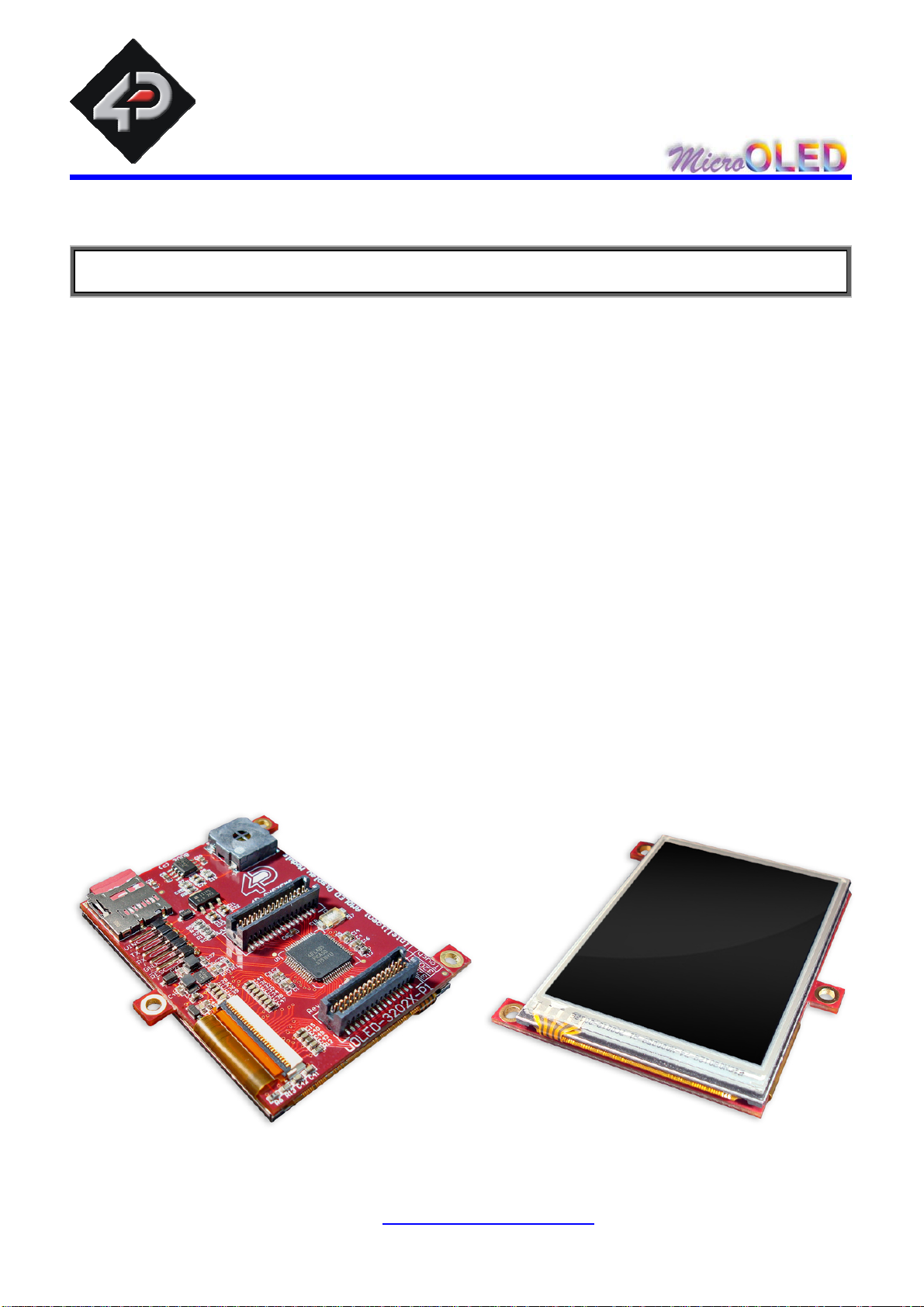
The µOLED-3202X-P1 series of modules are aimed at being integrated into a
variety of different applications via a wealth of features designed to facilitate any
given functionality quickly and cost effectively and thus reduce ‘time to market’.
These features are as follows:
• There are 4 modules in the µOLED-3202X-P1 series:
o µOLED-32024-P1 :
Diagonal : 2.4”
Screen Outline : 42.0 x 52.6 mm
Active Area: 36.7 x 49.0 mm
o µOLED-32024-P1T :
Same as µOLED-32024-P1 but with resistive touch screen.
o µOLED-32028-P1 :
Diagonal : 2.83”
Screen Outline : 49.1 x 67.3 mm
Active Area : 43.2 x 57.6 mm
o µOLED-32028-P1T :
Same as µOLED-32028-P1 but with resistive touch screen.
• QVGA 240 x RGB x 320 pixel resolution with 256, 65K or 262K true to life
colours enhanced AMOLED screen.
• Near 180 degree viewing angle.
• All modules use the same controller board. PCB Size: 49.1 x 67.3 x 11.0mm.
• Easy 5 pin user interface (VCC, TX, RX, GND, RESET) to any 4D micro-USB
module such as the µUSB-MB5 or the µUSB-CE5.
• Voltage supply from 4.5V to 5.5V, current @ 90mA nominal when using a
5.0V supply source.
• Onboard micro-SD (µSD) memory card adaptor with full FAT16 file support
for storing and executing 4DGL programs, files, icons, images, animations,
video clips and audio wave files. 64Mb to 2Gig µSD memory cards can be
purchased separately.
www.4dsystems.com.au
µ LED-3202X-P1
O
4
Page 5
4D SYSTEMS © 2008
Powered by the fully integrated PICASO-GFX Graphics Processor (PICASO-
GFX chip is also available for OEM volume users).
Built in extensive 4DGL graphics and system library functions. For all available
features and functions under the 4DGL programming language please visit the
4DGL web page http://www.4dsystems.com.au/developers/
2 x 30 pin headers for I/O expansion and future plug-in daughter boards.
Audio amplifier with a tiny 8 Ohms speaker for sound generation and wave file
playback.
Mechanical support via mounting tabs which can be snapped off.
www.4dsystems.com.au
µ LED-3202X-P1
O
5
Page 6
4D SYSTEMS © 2008
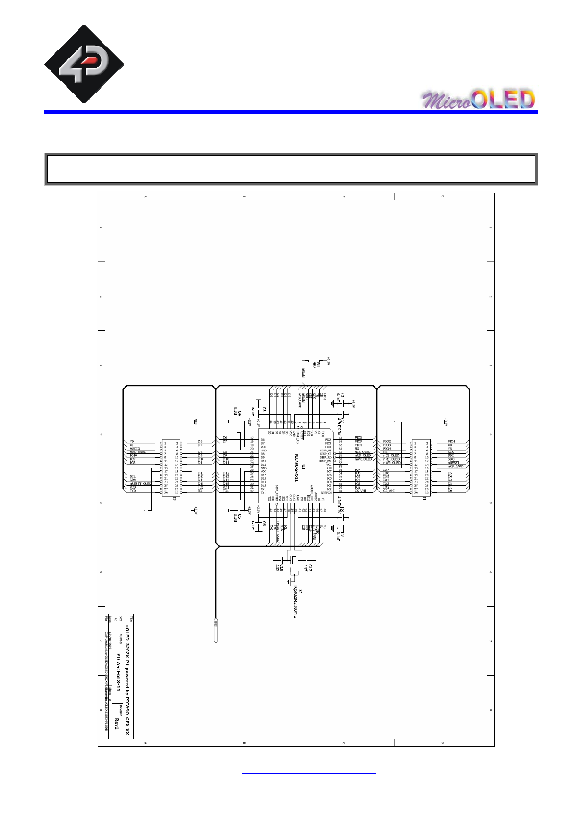
3 Circuit Diagram
www.4dsystems.com.au
µ LED-3202X-P1
O
6
Page 7

4D SYSTEMS © 2008
www.4dsystems.com.au
µ LED-3202X-P1
O
7
Page 8

4D SYSTEMS © 2008
www.4dsystems.com.au
µ LED-3202X-P1
O
8
Page 9
4D SYSTEMS © 2008
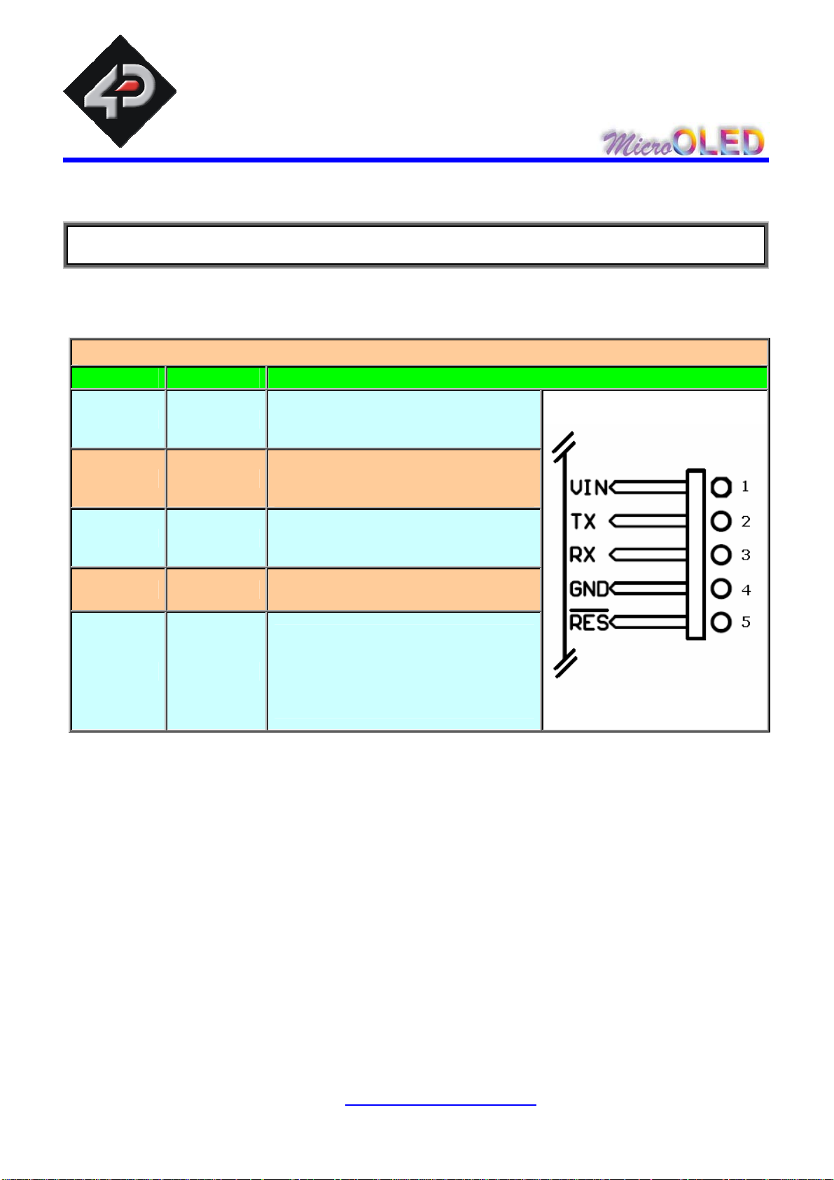
4 User Interface Pin Description
Power, Serial and micro-USB Interface
Pin Function Description
Main Power Supply input
1 VIN
2 TX
3 RX
4.5Volts to 5.5Volts. Nominal @
5Volts.
Serial Transmit Pin (Data Out),
COM0 TX. CMOS levels 0V to
3.3V
Serial Receive Pin (Data In),
COM0 RX. CMOS levels 0V to
VIN.
4 GND Ground.
External RESET signal for the
module and PICASO chip. Pull
5 RES
this pin Low for 20µsec or longer
to Reset the module. Not
required for normal usage.
www.4dsystems.com.au
µ LED-3202X-P1
O
9
Page 10

4D SYSTEMS © 2008
5 Expansion Ports Pin Description
EXPANSION PORT J1 (for future 4D add-on modules)
Pin Label Description
1 FIO2 Factory IO2 pin. (Reserved, do not use).
2 FIO1 Factory IO1 pin. (Reserved, do not use).
3 FIO3 Factory IO3 pin. (Reserved, do not use).
4 XR 4-Wire resistive touch screen right signal. (Reserved, do not use).
5 FIO4 Factory IO4 pin. (Reserved, do not use).
6 YU 4-Wire resistive touch screen top signal. (Reserved, do not use).
7 RS Display register select signal. (Reserved, do not use).
8 SCK SPI serial clock output for external SD card use only.
9 nCS_OLED OLED chip select signal. (Reserved, do not use).
10 SDI SPI serial data input for external SD card use only.
11 nRD_OLED OLED read strobe signal. (Reserved, do not use).
12 SDO SPI serial data output for external SD card use only.
13 nWR_OLED OLED write strobe signal. (Reserved, do not use).
14 nRESET Master RESET. Pull this pin Low for 20µsec or longer to Reset the module.
15 GND Ground.
16 nCS_CARD SD memory card chip select for external SD card use only.
17 IO7 General Purpose Input Output 7 pin.
18 3.3V Regulated 3.3 Volts output, availa ble current max 400mA .
19 IO6 General Purpose Input Output 6 pin.
20 D5 OLED data bus bit 5. (Reserved, do not use).
21 IO5 General Purpose Input Output 5 pin.
22 D4 OLED data bus bit 4. (Reserved, do not use).
23 IO4 General Purpose Input Output 4 pin.
24 D3 OLED data bus bit 3. (Reserved, do not use).
25 IO3 General Purpose Input Output 3 pin.
26 D2 OLED data bus bit 2. (Reserved, do not use).
27 IO2 General Purpose Input Output 2 pin.
28 D1 OLED data bus bit 1. (Reserved, do not use).
29 CS_VHI OLED DC-DC circuit enable signal. (Reserved, do not use).
30 D0 OLED data bus bit 0. (Reserved, do not use).
www.4dsystems.com.au
µ LED-3202X-P1
O
10
Page 11

4D SYSTEMS © 2008
EXPANSION PORT J2 (for future 4D add-on modules)
Pin Label Description
1 YD 4-Wire resistive touch screen bottom signal. (Reserved, do not use).
2 D6 OLED data bus bit 6. (Reserved, do not use).
3 XL 4-Wire resistive touch screen left signal. (Reserved, do not use).
4 D7 OLED data bus bit 7. (Reserved, do not use).
5 AUDIO
6 VCC Main Power Supply input 4.5Vol ts to 5.5Vol ts. Nominal @ 5Volts.
7 AUDIO_ENBL Logic Low will enable the audio amplifier, logic High will disable it.
8 D8 OLED data bus bit 8. (Reserved, do not use).
9 IO10 General Purpose Input Output 10 pin.
10 D9 OLED data bus bit 9. (Reserved, do not use).
11 IO9 General Purpose Input Output 9 pin.
12 D10 OLED data bus bit 10. (Reserved, do not use).
13 IO8 General Purpose Input Output 8 pin.
14 D11 OLED data bus bit 11. (Reserved, do not use).
15 GND Ground.
16 3.3V Regulated 3.3 Volts output, available current max 400mA.
17 GND Ground.
18 3.3V Regulated 3.3 Volts output, available current max 400mA.
19 N.C. No Connect.
20 D12 OLED data bus bit 12. (Reserved, do not use).
21 SCL I2C clock output.
22 D13 OLED data bus bit 13. (Reserved, do not use).
23 SDA I2C bi-directional data.
24 D14 OLED data bus bit 14. (Reserved, do not use).
25 nRESET_OLED OLED Reset signal. (Reserved, do not use).
26 D15 OLED data bus bit 15. (Reserved, do not use).
27 RX0 Asynchronous serial port 0 receive pin. COM0 Rx.
28 TX1 Asynchronous serial port 1 transmit pin. COM1 Tx.
29 TX0 Asynchronous serial port 0 transmit pin. COM0 Tx.
30 RX1 Asynchronous serial port 1 receive pin. COM1 Rx.
Pulse width modulated Audio output from PICASO. This pin is also input to
the onboard audio amplifier.
www.4dsystems.com.au
µ LED-3202X-P1
O
11
Page 12

4D SYSTEMS © 2008
6 USB to Serial Interface - microUSB
The µOLED-3202X-P1 module is required to be interfaced to a PC for uploading the
PICASO-GFX chip with user application 4DGL code. Using a standard USB cable
and any one of the 4D Systems micro-USB modules (µUSB-MB5 or µUSB-CE5)
as shown below, a PC to µOLED-3202X-P1 connection can be achieved simply.
The micro-USB interface is also used for PmmC (Personality module micro Code)
uploads. The PmmC allows the latest Operating System and 4DVM (4D Virtual
Machine) upgrades for the PICASO-GFX chip. The micro-USB module (optional
extra), simply connects to the µOLED-3202X-P1 module and captures the USB
data and converts it into serial CMOS level (0 to 3.3V) data. The micro-USB
modules and drivers are available from your local 4D distributor. This is an
optional extra product and is not included with the module.
µUSB-MB5
µUSB-CE5
www.4dsystems.com.au
µ LED-3202X-P1
O
12
Page 13

4D SYSTEMS © 2008
7 Mechanical Details
The module footprint is 49.1mm x 67.3mm x 11.0mm (excluding tabs).
www.4dsystems.com.au
µ LED-3202X-P1
O
13
Page 14
4D SYSTEMS © 2008
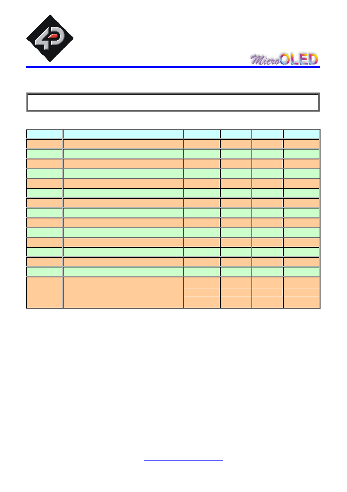
8 Specifications and Ratings
Symbol Characteristic Min Typ Max Units
VIN
I
TOP
TSTO
TPU
VTX
VRX
VIOIL
VIOIH
VIOOL
VIOOH
L
VA
Cr
Input Low Voltage on any I/O pin 0 -- 0.7 Volts
Input High Voltage on any I/O pin 2.6 -- 3.3 Volts
Output Low Voltage on any I/O pin
Output High Voltage on any I/O pin
Supply voltage 4.5 5.0 5.5 Volts
Current 70 90 190 mA
Operating temperature -10 -- 70 deg C
Storage temperature -30 -- 85 deg C
Power-up delay 900 1000 1100 msec
TX pin Voltage Out 0.4 3.0 3.3 Volts
RX pin Voltage In 0 2.4 Vin Volts
0 -- 0.4 Volts
2.6 -- 3.3 Volts
Luminance 50 -- 250 Cd/m2
Viewing Angle 160 170 179 degrees
Contrast Ratio 5000:1 10000:1
- -
LTOP
Operational Life Time @30% power
consumption
to half intensity
20,000 -- -- hours
www.4dsystems.com.au
µ LED-3202X-P1
O
14
Page 15

4D SYSTEMS © 2008
9 Available Models and Order Codes
• µOLED-32024-P1 :
o Diagonal : 2.4”
o Screen Outline : 42.0 x 52.6 mm
o Active Area: 36.7 x 49.0 mm
• µOLED-32024-P1T :
o Same as µOLED-32024-P1 but with resistive touch screen.
• µOLED-32028-P1 :
o Diagonal : 2.83”
o Screen Outline : 49.1 x 67.3 mm
o Active Area : 43.2 x 57.6 mm
• µOLED-32028-P1T :
o Same as µOLED-32028-P1 but with resistive touch screen.
NOTE!
Both the 2.4” and the 2.83” screens use the same controller board which is
designed to the dimensions of the 2.83” display. The 2.4” display on the
µOLED-32024-P1 and the µOLED-32024-P1T modules will appear smaller
on the larger controller board.
www.4dsystems.com.au
µ LED-3202X-P1
O
15
Page 16
4D SYSTEMS © 2008
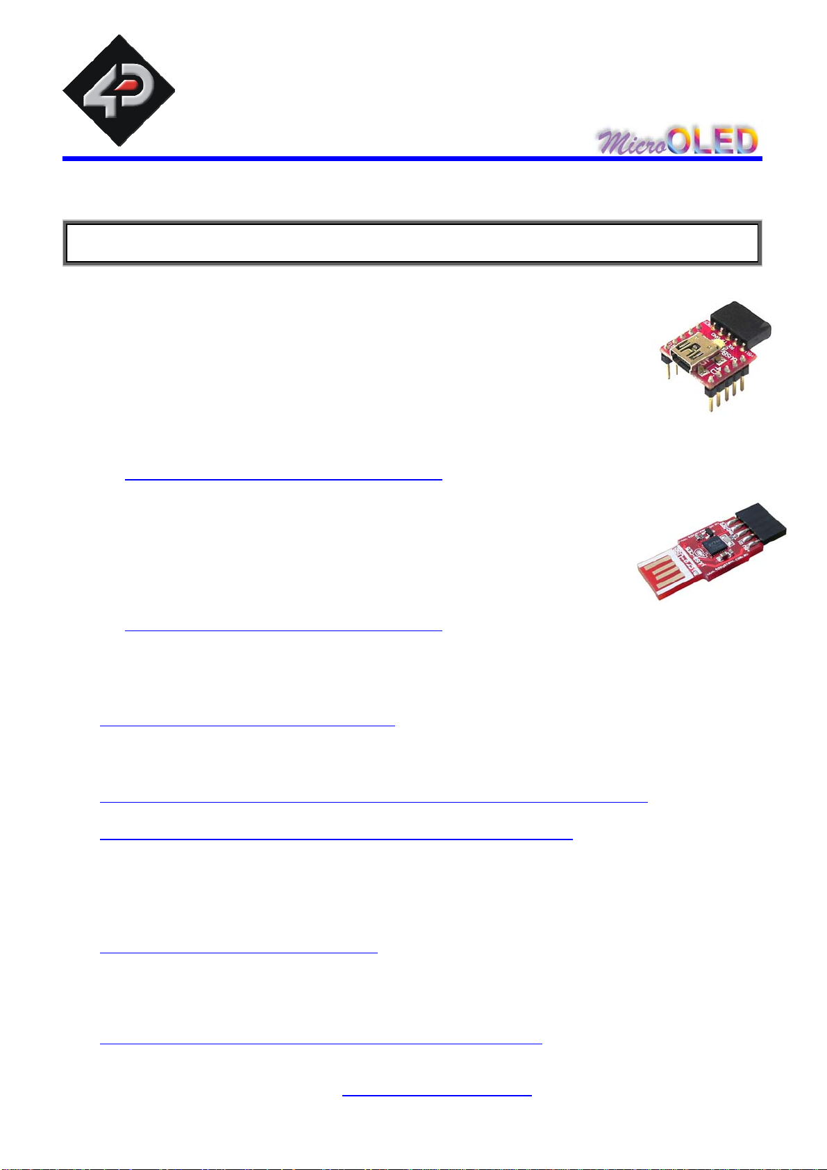
10 Related Products and Tools
µUSB-MB5
micro-USB module, USB to Serial Bridge, Silabs CP2102
Standard USB miniB connector
10 pin header provides the following signals:
5V, 3.3V, GND, Tx, Rx, Suspend,
DTR, CTS, RTS, GND
5 Volts supply @ 500mA, 3.3 Volts supply @ 100mA
Additional flow control signals, DTR, CTS, RTS
Available with an additional 5 pin header for the µOLED interface
www.4dsystems.com.au/prod.php?id=18
µUSB-CE5
micro-USB module, USB to Serial Bridge, FTDI Chipset
Plugs directly into USB port
5 pi n header provides the following signals:
5V, Rx, Tx, GND, Reset
5 Volts supply @ 500mA
www.4dsystems.com.au/prod.php?id=19
PmmC File for the µOLED-3202X-P1 modules
The latest PmmC system files for the modules can be downloaded from the individual
product pages at:
www.4dsystems.com.au/products.php
PmmC Loader PC Software Tool (free download)
Latest version of PmmC-Loader software tool can be downloaded from:
www.4dsystems.com.au/downloads/PmmC-Loader/Software/Windows/
and the User Guide can be found here:
www.4dsystems.com.au/downloads/PmmC-Loader/Docs/Pdf/
4DGL Workshop (free download)
This is the IDE plus editor plus compiler for all 4DGL user app lications. Everything is
provided in a single package to write, compile and download 4DGL application cod e
into the µOLED-3202X-P1 modules.
www.4dsystems.com.au/developers
4D Graphics Composer (free download)
The GC allows downloading of images/animations/movie clips into the micro-SD
memory card which can then be recalled and used within 4DGL user application code.
www.4dsystems.com.au/downloads/Graphics_Composer/
www.4dsystems.com.au
µ LED-3202X-P1
O
16
Page 17
4D SYSTEMS © 2008
11 Precautions
Avoid having a White Background. The more pixels that are lit up, the more
the display module will consume current. A full white screen will have the
highest power consumption.
Avoid having to display the same image/object on the screen for lengthy
periods of time. This will cause a burn-in or ‘image-sticking’ effect which is
a common occurrence with most types of display technologies and even
more so with AMOLEDs. Blank the screen after a while or dim it very low by
adjusting the contrast. Better still; implement a screen saver feature.
For further information refer to:
http://data.4dsystems.com.au/downloads/micro-OLED/Docs/4D_AMOLED_Presentation.pdf
www.4dsystems.com.au
µ LED-3202X-P1
O
17
Page 18

4D SYSTEMS © 2008
PROPRIETORY INFORMATION
The information contained in this document is the property of 4D Systems Pty. Ltd and may
be the subject of patents pending or granted, and must not be copied or disclosed with out
prior written permission. It should not be used for commercial purposes without prior
agreement in writing.
4D Systems Pty. Ltd endeavours to ensure that the information in this document is correct
and fairly stated but does not accept liability for any error or omission. The development of
4D Systems products and services is continuous and published information may not be up
to date. It is important to check the current position with 4D Systems.
Contact details are available from the company web site at www.4dsystems.com.au
All trademarks recognised and acknowledged.
Copyright 4D Systems Pty. Ltd. 2000-2008
DISCLAIMER OF WARRANTIES & LIMITATION OF LIABILITY
4D Systems Pty. Ltd. makes no warranty, either express or implied with respect to any
product, and specifically disclaims all other warranties, including, without limitation,
warranties for merchantability, non-infringement and fitness for any particular purpose. 4d
systems' sole obligation and liability for product defects shall be, at 4d systems' option, to
replace such defective product or refund to buyer the amount paid by buyer therefore. In no
event shall 4D Systems' liability exceed the buyer's purchase price.
The foregoing remedy shall be subject to buyer's written notification of defect and return of
the defective product within ninety (90) days of purchase. The foregoing remedy does not
apply to products that have been subjected to misuse (including without limitation static
discharge), neglect, accident or modification, or to products that have been soldered or
altered during assembly, or are otherwise not capable of being tested, or if damage occurs
as a result of the failure of buyer to follow specific instructions.
In no event shall 4D Systems be liable to the buyer or to any third party for any indirect,
incidental, special, consequential, punitive or exemplary damages (including without
limitation lost profits, lost savings, or loss of business opportunity) arising out of or relating to
any product or service provided or to be provided by 4D Systems, or the use or inability to
use the same, even if 4D Systems has been advised of the possibility of such damages.
www.4dsystems.com.au
µ LED-3202X-P1
O
18
 Loading...