

Page 1
µOLED-128-G1
USERS MANUAL
Intelligent OLED Display Module
For embedded applications with integrated micro-SD card support
Document Revision 1.0 (April 10th 2008)
4D Systems
Page 2
T
PROPRIETORY INFORMATION
The information contained in this document is the property of 4D Systems Pty. Ltd and may
be the subject of patents pending or granted, an d must not be copied or disclos ed with out
prior written permission. It should not be used for commercial purposes without prior
agreement in writing.
4D Systems Pty. Ltd. Endeavours to ensure that the information in this document is correct
and fairly stated but does not accept liability for any error or omission. The development of
4D Systems products and services is continuous and published information may not be up to
date. It is important to check the current position with 4D Systems.
Contact details are available from the company web site at www.4dsystems.com.au
All trademarks recognised and acknowledged.
Copyright 4D Systems Pty. Ltd. 2000-2008
DISCLAIMER OF WARRANTIES & LIMITATION OF LIABILITY
4D Systems Pty. Ltd. makes no warranty, either express or implied with respect to any
product, and specifically disclaims all other warranties, including, without limitation,
warranties for merchantability, non-infringement and fitness for any particular purpose. 4D
Systems' sole obligation and liability for product defects shall be, at 4d systems' option, to
replace such defective product or refund to buyer the amount paid by buyer therefor e. In
no event shall 4D Systems' liability exceed the buyer's purchase price.
he foregoing remedy shall be subject to buyer's written notification of defect and return of
the defective product within ninety (90) days of purchase. The foregoing remedy does not
apply to products that have been subjected to misuse (including without limitation static
discharge), neglect, accident or modification, or to products that have been soldered or
altered during assembly, or are otherwise not capable of being tested, or if damag e occurs
as a result of the failure of buyer to follow specific instructions.
In no event shall 4D Systems be liable to the buyer or to any third party for any indirect,
incidental, special, consequential, punitive or exemplary damages (including without
limitation lost profits, lost savings, or loss of business opportunity) arising out of or relating
to any product or service provided or to be provided by 4D Systems, or the use or inability
to use the same, even if 4D Systems has been advised of the possibility of such damages.
www.4dsystems.com.au
µ E G1
OL D-128-
2
Page 3

Table of contents
1. Introduction
Serial Command Platform
4DGL Platform
1.1 Features
2. Serial Command Platform
2.1 Command Protocol
Serial Interface
Auto Baud Detect
Serial Timing
Power-Up Reset
Splash Screen on Power Up
Auto Run uSD card Slide Show
2.2 General Command Set
2.2.1 Add User Bitmapped Character
2.2.2 Set Background Colour
2.2.3 Place Text button
2.2.4 Draw Circle
2.2.5 Block copy & Paste (Screen Bitmap Copy)
2.2.6 Display User Bitmapped Character
2.2.7 Erase Screen
2.2.8 Set Font Size
2.2.9 Draw TrianGle
2.2.10 Draw Polygon
2.2.11 Display Image
2.2.12 Draw Line
2.2.13 Opaque or Transparent Text
2.2.14 Put Pixel
2.2.15 Set pen Size
2.2.16 Read Pixel
2.2.17 Draw rectangle
2.2.18 Place String of ASCII Text (unformatted)
2.2.19 Place string of ASCII Text (formatted)
2.2.20 Place Text Character (formatted)
2.2.21 Place text Character (unformatted)
2.2.22 OLED DisplaY Control Functions
2.2.23 Version/Device Info Request
www.4dsystems.com.au
µ E G1
OL D-128-
3
Page 4

2.3 Display Specific Command set
2.3.1 Write to OLED Register
2.3.2 Display Scroll Control
2.3.3 Dim Screen Area
2.4 Extended Command set
2.4.1 initialise µSD Memory Card
2.4.2 Read Sector
2.4.3 Write Sector
2.4.4 read Byte
2.4.5 write Byte
2.4.6 Set Address
2.4.7 Copy Screen to Memory Card
2.4.8 Display Image/Icon from Memory Card
2.4.9 Play Video/Animation clip from Memory Card
2.4.10 Display Object from Memory Card
2.4.11 Run Program from Memory Card
2.4.12 Delay
2.4.13 Set Counter
2.4.14 Decrement Counter
2.4.15 Jump to Address If Counter Not Zero
2.4.16 Jump to Address
2.4.17 Exit Program from Memory Card
3. 4DGL Platform
4. User Interface
Main Interface Block (10 pin Header)
Serial Platform : Auto-Run Slide Show Connection
Serial Platform : host microcontroller interface
Serial/4DGL Platform : micro-USB interface
5. Personality-module-micro Code (PmmC)
6. Circuit Diagram
7. Mechanical Details
8. Specifications & Ratings
9. Precautions
10. Related Products and Software Tools
www.4dsystems.com.au
µ E G1
OL D-128-
4
Page 5

1 Introduction
The µOLED-128-G1 is a compact and cost effective all in one ‘SMART”
display module using the latest state of the art Passive Matrix OLED
(PMOLED) technology with an embedded GOLDELOX graphics controller
that delivers ‘stand-alone’ functionality to any project. The module is
designed to operate under 2 different software platforms; the Serial
Command platform or the 4DGL (4D Graphics Language) platform.
Serial Command Platform:
The serial command platform allows the µOLED-128-G1 module to be
used as slave device connected to an external host. The host can be any
controller such as a PIC, AVR, ARM, STAMP, etc. or even a PC where all
screen related functions are sent using a simple protocol via the serial
interface. Serial commands may comprise of a single byte or multiple
bytes of data depending on the command type. The serial platform allows
users to develop their application using their favourite microcontroller and
software development tools.
Note: The µOLED-128-G1 is preloaded with the serial command
software platform as the factory default.
4DGL Platform:
4DGL is a graphics oriented language allowing the developer to write
applications in a high level language (syntax similar to popular languages
such as BASIC, C, Pascal, etc.) and run it directly on the GOLDELOX
processor embedded in the µOLED-128-G1 module.
The rich set of built in library functions and the high level syntax allows
the user to take complete control of all available hardware resources such
as the Serial Port, Graphics Display, micro-SD card, I/O pins, etc. This
eliminates the need for an external host microcontroller to drive the
µOLED-128-G1 module via serial commands. It provides the user
complete independence to quickly develop powerful applications.
Note: The 4DGL Platform will need to be uploaded into the module using
the relevant PmmC file. You will need the PmmC-Loader software tool
to assist in the process. The links to these are provided on the µOLED-
128-G1 product page.
www.4dsystems.com.au
µ E G1
OL D-128-
5
Page 6
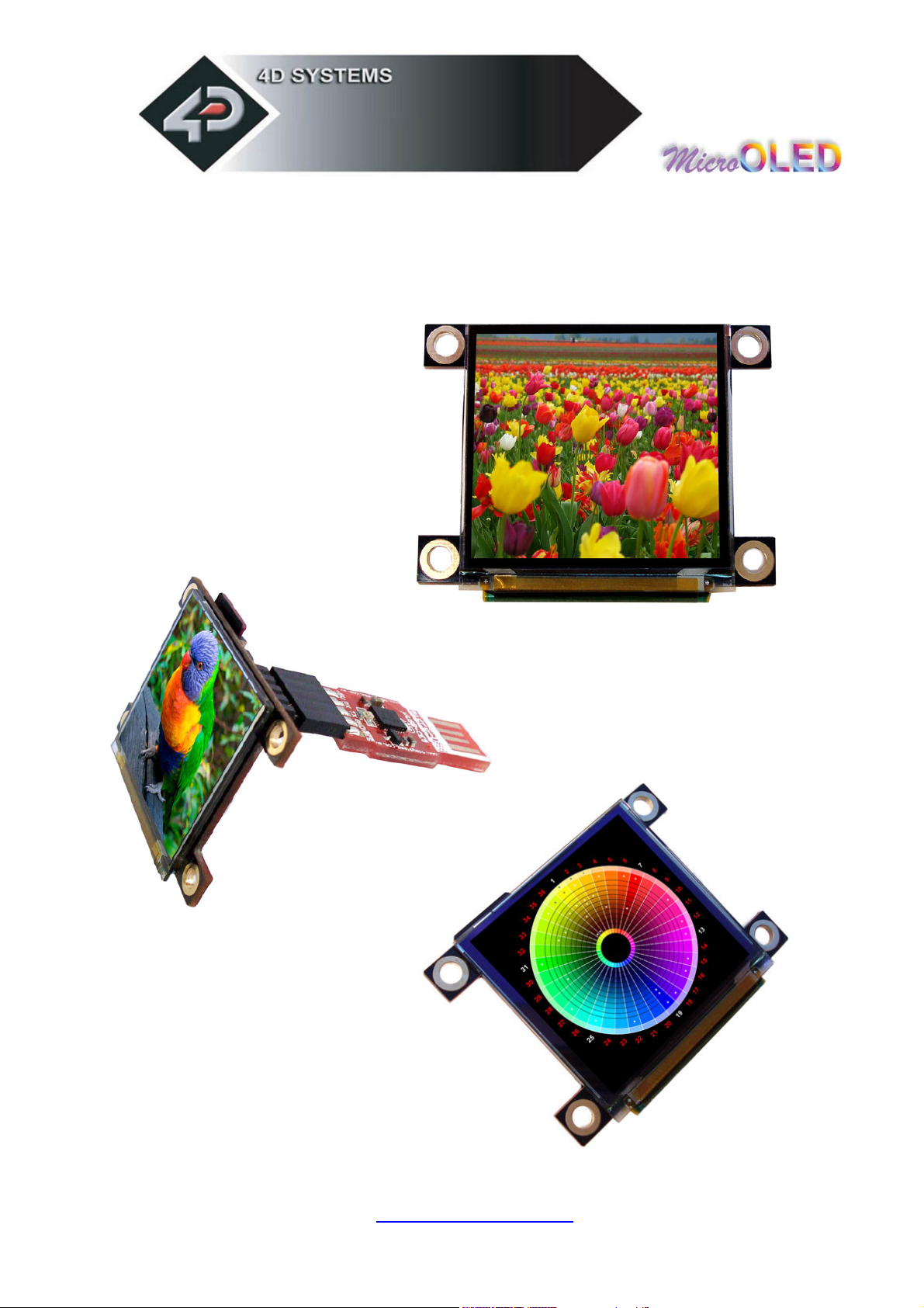
Figures below show some of the graphics capability of the µOLED-128-G1.
www.4dsystems.com.au
µ E G1
OL D-128-
6
Page 7
1.1 Features
The µOLED-128-G1 is aimed at being integrated into a variety of different
applications via a wealth of features designed to facilitate any given
functionality quickly and cost effectively and thus reduce ‘time to market’.
These features are as follows:
128 x 128 resolution, 256/65K true to life colours, PMOLED screen.
1.5” diagonal size, 45.5 x 33.5 x 6.3mm. Active Area: 27mm x 27mm.
No backlighting with near 180° viewing angle.
Easy 5 pin interface to any host device: VCC, TX, RX, GND, RESET
Voltage supply from 3.6V to 6.0V, current @40mA nominal when
us i n g a 5.0V s u p p l y. Note: The module may need to be supplied with a
voltage greater than 4.0 volts when using it with a SD memory card.
Serial RS-232 (0V to 3.3V) with auto-baud feature (300 to 256K baud).
Rx line has built in series current limit resistor and a pull-up resistor.
Powered by the 4D Labs GOLDELOX processor (also available as
separate OEM IC for volume users).
2 different operating platforms; the Serial Command platform (factory
default) or the 4DGL (4D Graphics Language) platform.
Optional USB to Serial interface via the 4D micro-USB (µUSB-MB5 or
µUSB-CE5) modules.
Onboard micro-SD (µSD) memory card adaptor for storing of icons,
images, animations, etc. 64Mb to 2Gig µSD memory cards can be
purchased separately.
Rich set of built in graphics commands and functions.
www.4dsystems.com.au
µ E G1
OL D-128-
7
Page 8
2 Serial Command Platform
The heart of the Serial Platform is the easy to understand command set.
This comprises of easy to learn instructions that provide a full text and
graphical user interface. The commands are sent to the µOLED-128-G1
via its serial connection. The command set is grouped into 3 sections:
• General Command Set
• Display Specific Command Set
• Extended Command Set (uSD Memory Card commands)
Each Command set is described in detail in the following sections.
NOTE!
Serial Data Format: 8 Bits, No Parity, 1 Stop Bit.
www.4dsystems.com.au
µ E G1
OL D-128-
8
Page 9

2.1 Serial Command Protocol
The following applies only to the Serial Platform and each serial command
is described in detail and how it can be used. Please note that all
command examples listed in this section are in hex (00hex). Due to the
high colour depth of the display module, a pixel colour value will not fit
into a single byte, a byte can only hold a maximum value of 255.
Therefore the colour is represented as a 2 byte value, colour(msb:lsb).
The most significant byte (msb) is transmitted first followed by the least
significant byte (lsb). This format is called the big endian. So for a 2 byte
colour value of 013Fhex the byte order can be shown as
(01hex),(3Fhex).
NOTE: When transmitting the command and data bytes, do not include
any separators such as commas ‘,’ or spaces ‘ ‘ or brackets ‘(‘ ‘)’ between
the bytes. The examples show these separators purely for legibility; these
must not be included when transmitting data to the µOLED-128-G1
module.
Serial Interface:
The µOLED-128-G1 needs to be connected via a serial link to a host
system. The host uses this serial link to send commands to the module so
that characters and graphics can be displayed on the screen. Use the
signal pin-outs as well as the application example shown in the “User
Interface” section for correct connection to the host.
Auto Baud Detect:
As previously mentioned, the module has an auto-baud detect feature
which can operate from 300 baud to 256K baud. Prior to any
commands being sent to the module, it must first be initialized by sending
the ASCII character ‘U’ (55h) after power-up. This will allow the module
to determine and lock on to the baud rate of the host automatically
without needing any further setup. This must be done every time the
module is powered up or reset.
If the host needs to change the baud rate, the module must be powered
down and powered back up again or reset. The “U” command cannot be
used to change the baud rate during the middle of normal usage.
www.4dsystems.com.au
µ E G1
OL D-128-
9
Page 10

Serial Timing:
Each serial command is made up of a sequence of data bytes. Some
commands are single byte and others are multiple bytes. When a
command is sent, the module will reply back with a single acknowledge
byte called the ACK (06hex). This tells the host controller that the
command was understood and the operation is completed. It will take the
module anywhere between 1 to several milliseconds to reply back with an
ACK, depending on the command and the operation it has to perform.
If the module receives a command that it does not understand it will
reply back with a negative acknowledge called the NAK (15hex).
For example, if a command has 5 bytes but only 4 bytes are sent, the
command will not be executed and the µOLED-128-G1 will wait until
another byte is sent before trying to execute the command. There is no
timeout when incomplete commands are sent. The module will reply back
with a NAK for each invalid command it receives. For correct operation
make sure the command bytes are sent in the correct sequence.
Power-Up Reset:
When the µOLED-128-G1 comes out of a power up reset, it initialises
the Graphics RAM and the internal Display registers. Allow up to 1 second
before attempting to communicate with the module. The power up
sequence of events should be as follows:
Allow up to 1000ms after power-up for voltages to settle and
internal initialisations to complete. Do not attempt to communicate
with the module during this period. The module may send garbage
on its Tx Data line during this period; the host should disregard any
data.
Within 100ms of powering up, the host should make sure it has its
transmit (TX) line pulled HIGH. If the host TX (module Rx) is LOW
after the 100ms period, it may misinterpret this as the START bit
and lock onto some unknown Baud Rate.
The host must transmit the ASCII ‘U’ (capital U, 55hex) as the first
command so the module can lock onto the host’s serial baud rate.
This is called “Auto Bauding”. The module will respond with an
‘ACK’ (06hex). See previous section.
The module is now ready to accept screen function commands from
the host.
www.4dsystems.com.au
µ E G1
OL D-128-
10
Page 11

Splash Screen on Power Up:
The µOLED-128-G1 will wait up to 5 seconds with its screen blank for
the host to transmit the Auto-Baud character (‘U’). If the host has not
transmitted the Auto Baud character by the end of this period the module
will display its splash screen. If the host has transmitted the Auto Baud
character the screen will remain blank. This wait period is for those
customer specific applications where the splash screen is undesired.
Auto Run uSD Card Slide Show:
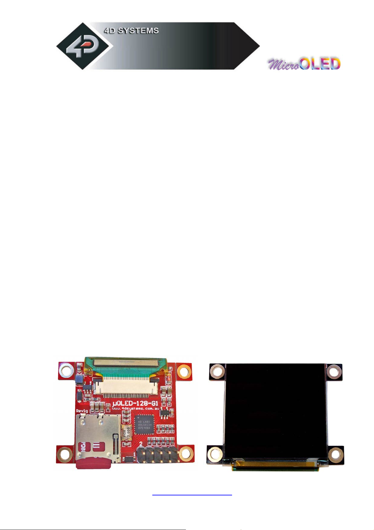
The µOLED-128-G1 module is equipped to accept memory cards. There
is a 10 way header at the back of the unit (on the component side).
Upon power-up, if a jumper shunt is inserted across pins 6 and 8 and
there is a preloaded slide show in the µSD memory card, the module will
automatically play/display these. The memory cards are supplied as blank
separate products and as such the user will have to upload a slide show
composition to the card to benefit from this auto play feature. For normal
usage this jumper must be removed.
See section 4 “User Interface” for further details.
www.4dsystems.com.au
µ E G1
OL D-128-
11
Page 12
2.2 General Command Set
General Command Set Live Object µSD Card
(A) Add User Bitmapped Character √
(B) Set Background Colour √ √ √
(b) Place Text button √ √ √
(C) Draw Circle √ √ √
(c) Block copy and Paste (bitmap copy) √
(D) Display User Bitmapped Character √
(E) Erase Screen √ √ √
(F) Font Size √ √ √
(G) Draw TrianGle √ √ √
(g) Draw Polygon √ √ √
(I) Display Image √
(L) Draw Line √ √ √
(O) Opaque or Transparent Text √ √ √
(P) Put Pixel √
(p) Set pen Size √ √ √
(R) Read Pixel √
(r) Draw rectangle √ √ √
(S) Place String of ASCII Text (unformatted) √ √ √
(s) Place string of ASCII Text (formatted) √ √ √
(T) Place Text Character (formatted) √ √ √
(t) Place text Character (unformatted) √ √ √
(V) Version/Device Info Request √
(Y) OLED DisplaY Control functions √ √ √
NOTES:
Live
: Those commands that can be sent via the serial link and executed by the uOLED
module.
Object : Those commands that can be recalled from the memory card at any time by the host
and displayed on the screen using the “Display Object from Memory Card”
command.
µSD Card : Those commands that can reside and be executed from inside the memory card.
www.4dsystems.com.au
µ E G1
OL D-128-
12
Page 13

2.2.1 Add User Bitmapped Character (A)
Syntax : cmd, char#, data1, data2, …….., data8
cmd : 41hex, Aascii
char# : bitmap character number to add to memory:
range is 0 to 31 (00h to 1Fh), 32 characters of 8x8 format.
data1 to data8 : 8 data bytes that make up the composition and
format of the bitmapped character. The 8x8 bitmap composition is 1
byte wide (8bits) by 8 bytes deep.
Description : This command will add a user defined bitmapped
character into the internal memory.
Example1: 41hex, 01hex, 18hex, 24hex, 42hex, 81hex, 81hex,
42hex, 24hex, 18hex
This adds and saves user defined 8x8 bitmap as character number 1
into memory as seen below.
b7 b6 b5 b4 b3 b2 b1 b0
data1 (hex = 18h)
data2 (hex = 24h)
data3 (hex = 42h)
data4 (hex = 81h)
data5 (hex = 81h)
data6 (hex = 42h)
data7 (hex = 24h)
data8 (hex = 18h)
Example of a 8x8 user defined bitmap
www.4dsystems.com.au
µ E G1
OL D-128-
13
Page 14

2.2.2 Set Background Colour (B)
Syntax : cmd, colour(msb:lsb)
cmd : 42hex, Bascii
colour(msb:lsb) : pixel colour value: 2 bytes (16 bits) msb:lsb
65,536 colours to choose from
Black = 0000hex, 0dec
White = FFFFhex, 65,535dec, 1111111111111111bin
Description : This command sets the current background colour.
Once this command is sent, only the background colour will change.
Any other object on the screen with a different colour value will not
be affected.
Example : 42hex, FFFFhex
Set the background colour to value 65,535 (white).
www.4dsystems.com.au
µ E G1
OL D-128-
14
Page 15

2.2.3 Text button (b)
Syntax : cmd, state, x, y, buttonColour(msb:lsb), font,
textColour(msb:lsb), width, height, ”string”, terminator
cmd : 62hex, bascii
state : Specifies whether the displayed button is drawn as UP” (not
pressed) or DOWN (pressed). 0 = Button Down (pressed)
1 = Button Up (not pressed)
x : top left horizontal start position of the button
y : top left vertical start position of the button
buttonColour(msb:lsb) : 2 byte button colour value
font : 0 = 5x7 font, 1 = 8x8 font, 2 = 8x12 font. This has
precedence and does not affect the Font command.
textColour(msb:lsb) : 2 byte text colour value
width : text width or horizontal size of the characters in the string,
effects the width of the button.
height : text height or vertical size of the characters in the string,
effects the height of the button.
”string” : string of ASCII characters (limit the string to line width)
terminator : the string must be terminated with 00hex
Description : This command will place a Text button similar to the
ones used in a PC Windows environment. (x, y) refers to the top left
corner of the button and the size of the button is automatically
calculated and drawn on the screen with the text relatively justified
inside the button box. The button can be displayed in an UP (button
not pressed) or DOWN (button pressed) position by specifying the
appropriate value in the state byte. Separate button and text colours
provide many variations in appearance and format.
www.4dsystems.com.au
µ E G1
OL D-128-
15
Page 16
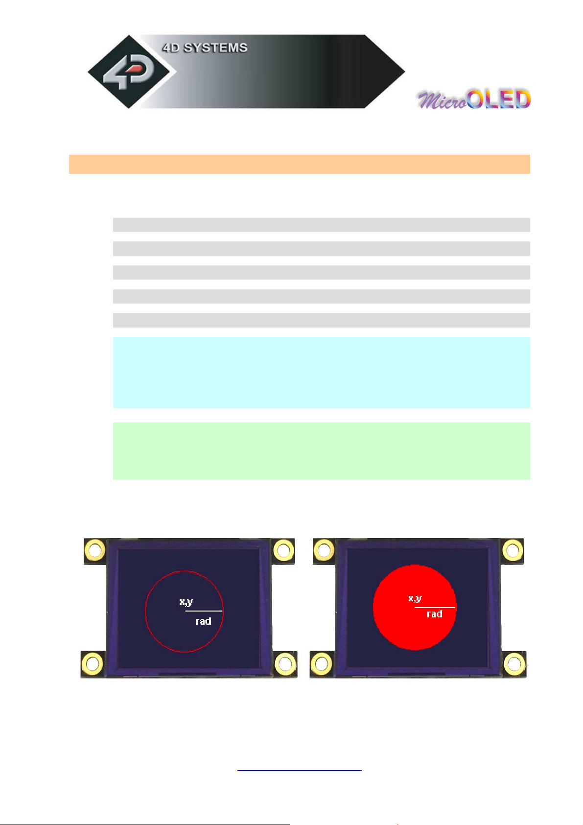
2.2.4 Draw Circle (C)
Syntax : cmd, x, y, rad, colour(msb:lsb)
cmd : 43hex, Cascii
x : circle centre horizontal position.
y : circle centre vertical position.
rad : radius size of the circle.
colour(msb:lsb) : 2 byte circle colour value
Description : This command will draw a coloured circle centred at
(x, y) with a radius determined by the value of rad. The circle can
be either solid or wire frame (empty) depending on the value of the
Pen Size (see Set Pen Size command). When Pen Size = 0 circle is
solid, Pen Size = 1 circle is wire frame.
Example : 43hex, 3Fhex, 3Fhex, 22hex, 00hex, 1Fhex
Draws a RED circle (001Fhex) centred at x = 63dec (3Fhex) and y =
63dec (3Fhex) with a radius of 34dec (22hex).
When Pen Size = 1 When Pen Size = 0
www.4dsystems.com.au
µ E G1
OL D-128-
16
Page 17

2.2.5 Block copy & Paste (Screen Bitmap Copy) (c)
Syntax : cmd, xs, ys, xd, yd, width, height
cmd : 63hex, cascii
xs: top left horizontal start position of block to be copied (source).
ys: top left vertical start position of block to be copied (source).
xd: top left horizontal start position of where copied block is to be
pasted (destination).
yd: top left vertical start position of where the copied block is to be
pasted (destination).
width: width of block to be copied (source).
height: height of block to be copied (source).
Description : This command copies an area of a bitmap block of
specified size. The start location of the block to be copied is
represented by xs, ys (top left corner) and the size of the area to be
copied is represented by width and height parameters. The start
location of where the block is to be pasted (destination) is
represented by xd, yd (top left corner).
This is a very powerful feature for animating objects, smooth
scrolling, implementing a windowing system or copying patterns
across the screen to make borders or tiles.
www.4dsystems.com.au
µ E G1
OL D-128-
17
Page 18

2.2.6 Display User Bitmapped Character (D)
Syntax : cmd, char#, x, y, colour(msb:lsb)
cmd : 44hex, Dascii
char# : which user defined character number to display from the
selected group. 0dec to 31dec (00hex to 1Fhex), of 8x8 format.
x : horizontal display position of the character.
y : vertical display position of the character.
colour(msb:lsb) : 2 byte bitmap colour value.
Description : This command displays the previously defined user
bitmapped character at location (x, y) on the screen. User defined
bitmaps allow drawing & displaying unlimited graphic patterns quickly
& effectively.
Example 1: 44hex, 01hex , 00hex, 00hex, F8hex, 00hex
Display 8x8 bitmap character number 1 at x=0, y=0, colour=red
Example 2: 44hex, 01hex, 08hex, 00hex, 07hex, E0hex
Display 8x8 bitmap character number 1 at x=8, y=0, colour=green
Example 3: 44hex , 01hex, 10hex, 00hex, 00hex, 1Fhex
Display 8x8 bitmap character number 1 at x=16, y=0, colour=blue
www.4dsystems.com.au
µ E G1
OL D-128-
18
Page 19

2.2.7 Erase Screen (E)
Syntax : cmd
cmd : 45hex, Eascii
Description : This command clears the entire screen using the
current background colour.
Example : 45hex
Clear the screen.
www.4dsystems.com.au
µ E G1
OL D-128-
19
Page 20

2.2.8 Set Font Size (F)
Syntax : cmd, size
cmd : 46hex, Fascii
size : = 00hex : 5x7 small size font
= 01hex : 8x8 medium size font
= 02hex : 8x12 large size font
Description : This command will change the size of the font
according to the value set by size. Changes take place after the
command is sent. Any character on the screen with the old font size
will remain as it was.
Example1: 46hex, 00hex Select small 5x7 fonts
Example1: 46hex, 01hex Select medium 8x8 fonts
Example1: 46hex, 02hex Select large 8x12 fonts
www.4dsystems.com.au
µ E G1
OL D-128-
20
Page 21
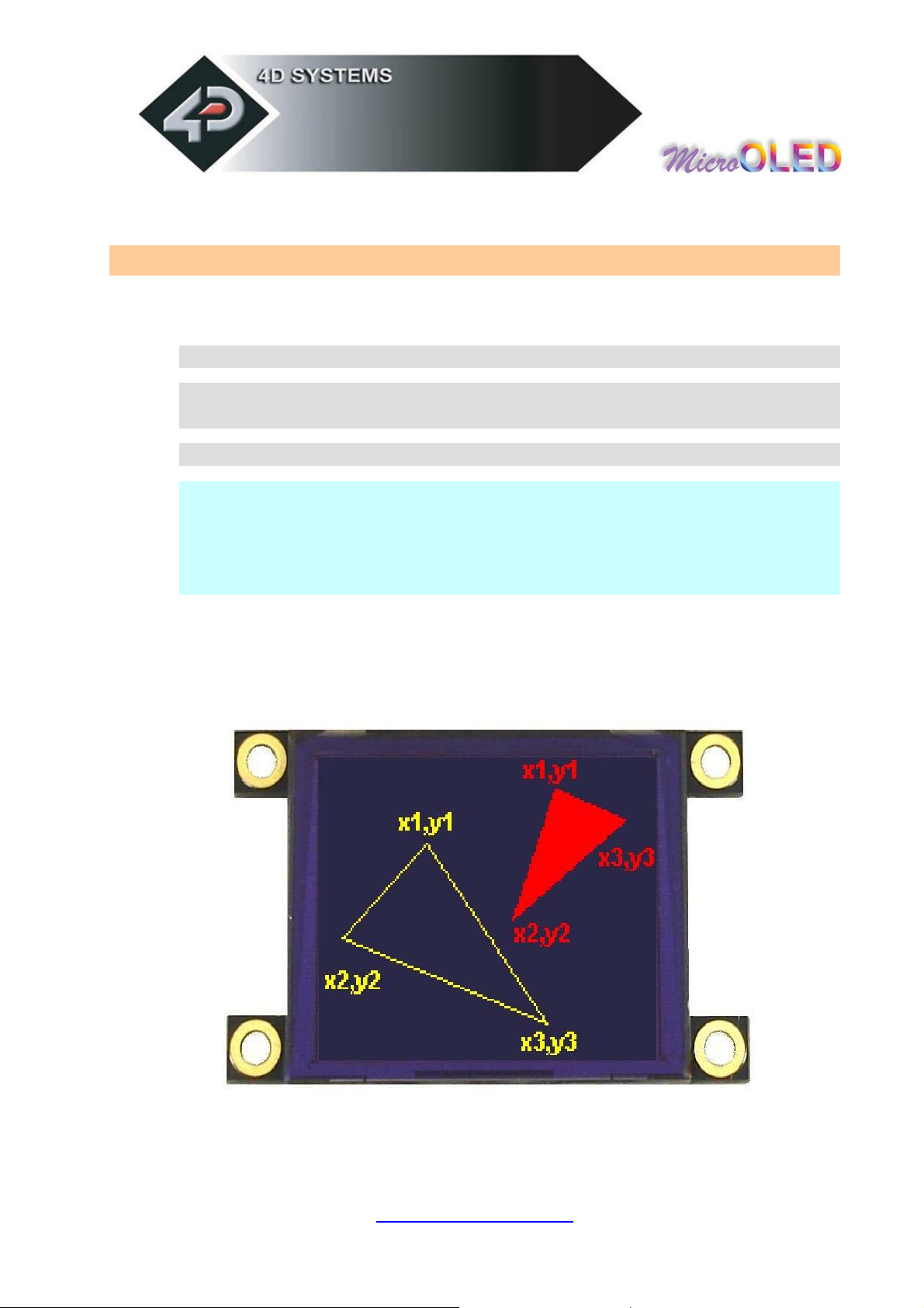
2.2.9 Draw TrianGle (G)
Syntax : cmd, x1, y1, x2, y2, x3, y3, colour(msb:lsb)
cmd : 47hex, Gascii
x1, y1, x2, y2, x3, y3 : 3 vertices of the triangle. These must be
specified in an anti-clockwise fashion.
colour(msb:lsb) : 2 byte triangle colour value
Description : This command draws a Solid/Empty triangle. The
vertices must be specified in an anti-clock wise manner, i.e.
x2 < x1, x3 > x2, y2 > y1, y3 > y1.
A solid or a wire frame triangle is determined by the value of the Pen
Size setting, i.e. 0 = solid, 1 = wire frame.
www.4dsystems.com.au
µ E G1
OL D-128-
21
Page 22
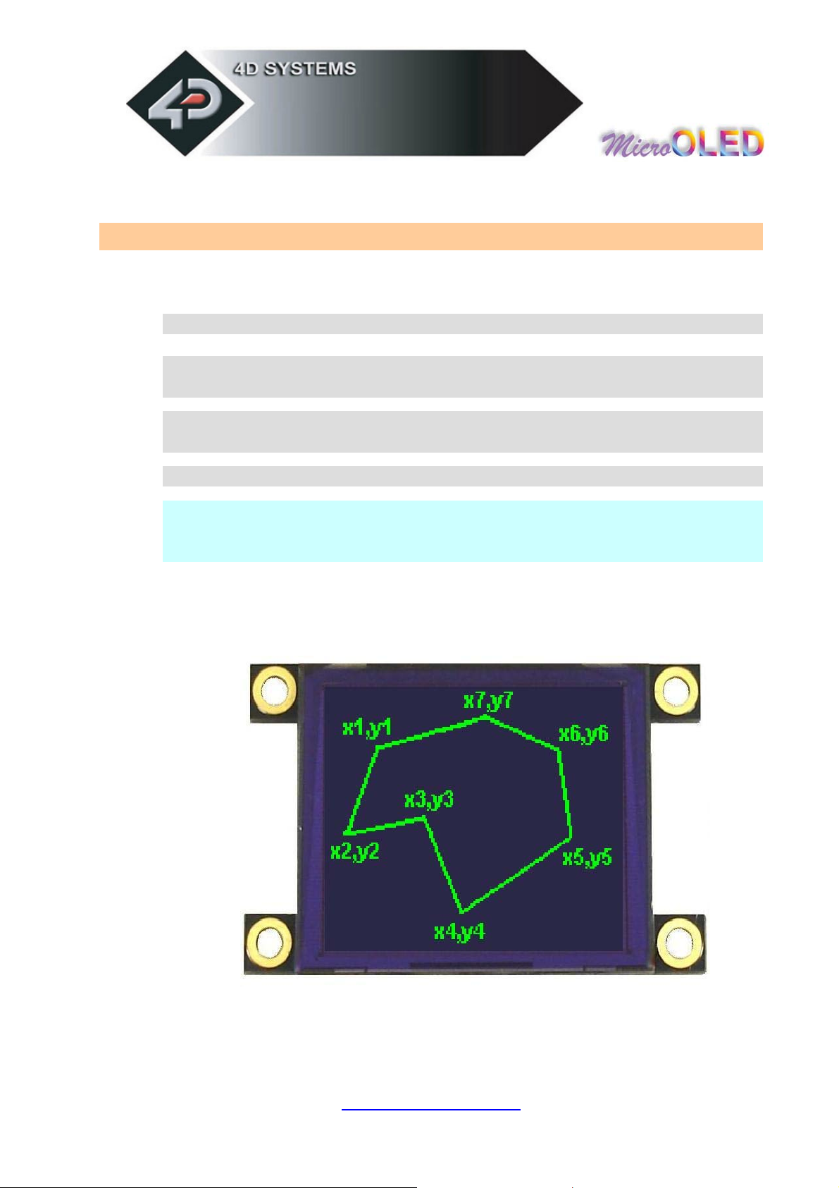
2.2.10 Draw Polygon (g)
Syntax : cmd, vertices, x1, y1, .. .. .. .. xn, yn, colour(msb:lsb)
cmd : 67hex, g ascii
vertices : number of vertices from 3 to 7. Specifies the number of
vertices of the polygon.
(x1, y1) .. .. .. (xn, yn) : vertices of the polygon. These can be
specified in any fashion.
colour(msb:lsb) : 2 byte polygon colour value
Description : This command draws an Empty/Wire Frame polygon.
Up to 7 vertices can be specified in any manner. Currently only a
wire frame polygon is supported.
www.4dsystems.com.au
µ E G1
OL D-128-
22
Page 23

2.2.11 Display Image (I)
Syntax : cmd, x, y, width, height, colourMode, pixel1, .. pixelN
cmd : 49hex, Iascii
x : Image horizontal start position (top left corner)
y : Image vertical start position (top left corner)
width : horizontal size of the image
height : vertical size of the image
colourMode : 8dec = 256 colour mode, 8bits/1byte per pixel
16dec = 65K colour mode, 16bits/2bytes per pixel
pixel1..pixelN : image pixel data and N is the total number of pixels
N = height x width when colourMode = 8
N = height x width x 2 when colourMode = 16
Description : This command displays a bitmap image on to the
screen with the top left corner specified by (x, y) and size of the
image specified by width and height parameters. This command is
more effective than using the “Put Pixel” command, where there are
no overheads in specifying the x, y location of each pixel.
www.4dsystems.com.au
µ E G1
OL D-128-
23
Page 24

2.2.12 Draw Line (L)
Syntax : cmd, x1, y1, x2, y2, colour(msb:lsb)
cmd : 4Chex, Lascii
x1 : horizontal position of line start.
y1 : vertical position of line start.
x2 : horizontal position of line end.
y2 : vertical position of line end.
colour(msb:lsb) : 2 byte line colour value
Description : This command will draw a coloured line from point
(x1, y1) to point (x2, y2) on the screen.
Example : 4Chex, 00hex, 00hex, 7Fhex, 7Fhex, FFhex, FFhex
Draws a white line from (x1=0, y1=0) to (x2=127, y2=127).
www.4dsystems.com.au
µ E G1
OL D-128-
24
Page 25
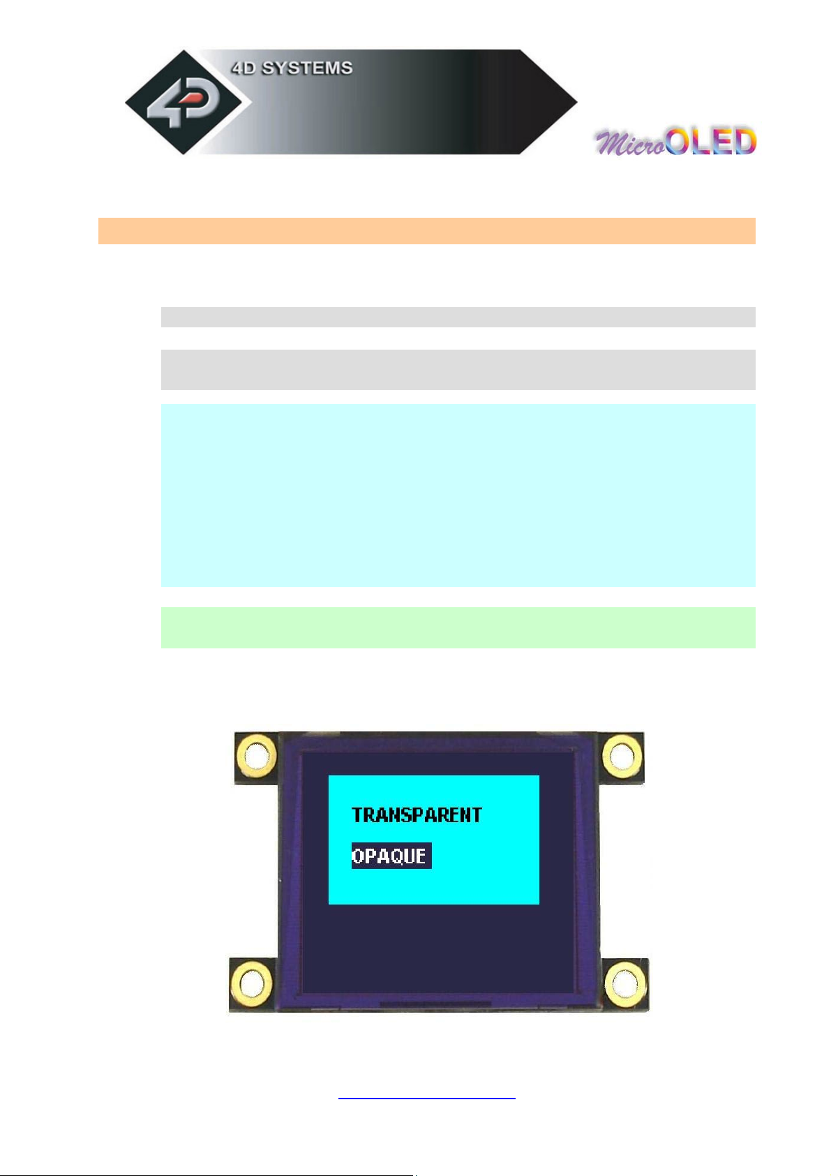
2.2.13 Opaque / Transparent Text (O)
Syntax : cmd, mode
cmd : 4Fhex, Oascii
mode: = 00hex: Transparent, objects behind text are visible.
= 01hex: Opaque, objects behind text blocked by background
Description : This command will change the attribute of the text so
that an object behind the text can either be blocked or transparent.
Changes take place after the command is sent.
This command will change the attribute so that when a character is
written, it will either write just the character alone (Transparent
Mode) so any original character will be seen as well as the new, or
overwrite any existing data with the new character.
Example1: 4Fhex, 00hex Transparent Text Mode
Example2: 4Fhex, 01hex Opaque Text Mode
www.4dsystems.com.au
µ E G1
OL D-128-
25
Page 26

2.2.14 Put Pixel (P)
Syntax : cmd, x, y, colour(msb:lsb)
cmd : 50hex, Pascii
x : horizontal pixel position.
y : vertical pixel position.
colour : pixel colour value: 2 bytes (16 bits) msb, lsb
65,536 colours to choose from
Black = 0000hex, 0dec
White = FFFFhex, 65,535dec, 1111111111111111bin
Description : This command will put a coloured pixel at location (x,
y) on the screen.
Example : 50hex, 01hex, 0Ahex, FFhex, FFhex
Plots a white (FFFFhex) pixel at location x = 01dec (01hex) and y =
10dec (0Ahex).
www.4dsystems.com.au
µ E G1
OL D-128-
26
Page 27

2.2.15 Set pen Size (p)
Syntax : cmd, size
cmd : 70hex, p ascii
size : = 00hex : All objects are solid
= 01hex : All objects are wire frame (empty)
Description : This command determines if certain graphics objects
are drawn in solid or wire frame fashion.
Example1: 70hex, 00hex All objects will be drawn solid
Example1: 70hex, 01hex All objects will be drawn wire frame.
www.4dsystems.com.au
µ E G1
OL D-128-
27
Page 28

2.2.16 Read Pixel (R)
Syntax : cmd, x, y
cmd : 52hex, Rascii
x : horizontal pixel position.
y : vertical pixel position.
Description : This command will read the colour value of pixel at
location (x, y) on the screen and return it to the host. This is a
useful command when for example a white pointer is moved across
the screen and the host can read the colour on the screen and switch
the colour of the pointer when it’s on top of a light coloured area.
Example : 52hex, 01hex, 01hex
µOLED reply : 00hex, 1Fhex
Reads a blue (001Fhex) pixel at location x = 1dec (01hex) and y =
1dec (01hex).
www.4dsystems.com.au
µ E G1
OL D-128-
28
Page 29

2.2.17 Draw rectangle (r)
Syntax : cmd, x1, y1, x2, y2, colour(msb:lsb)
cmd : 72hex, r ascii
x1 : top left horizontal start position of rectangle.
y1 : top left vertical start position of rectangle.
x2 : bottom right horizontal end position.
y2 : bottom right vertical end position.
colour(msb:lsb) : 2 byte rectangle colour value
Description : This command will draw a rectangle of specified area
on the screen. x1, y1 refers to the top left corner of the area and
x2, y2 refers to the bottom right hand corner of the rectangle on the
screen. If colour is chosen to be that of the background then the
effect will be erasure. If Pen Size value was previously set to 0
rectangle will be solid, otherwise wire frame if value was 1.
Example : 70hex, 00hex, 00hex, 10hex, 10hex, 00hex, 1Fhex
Draws a RED (001Fhex) rectangle that has its top left corner at
x1=0, y1=0 and its bottom right corner at x2=16, y2=16.
www.4dsystems.com.au
µ E G1
OL D-128-
29
Page 30

2.2.18 Place String of Ascii Text(unformatted) (S)
Syntax : cmd, x, y, font, colour(msb:lsb), width, height, “string”,
terminator
cmd : 53hex, Sascii
x : the horizontal start position of string (in pixels).
y : the vertical start position of string (in pixels).
font : 0 = 5x7 font, 1 = 8x8 font, 2 = 8x12 font. This has
precedence over the Font command but does not effect the previous
font selection.
colour(msb:lsb) : 2 byte colour value of the string.
width : horizontal size of the string characters, n x normal size
height : vertical size of the string characters, m x normal size
“string” : string of ASCII characters (max 256 characters)
terminator : the string must be terminated with 00hex
Description : This command allows the display of a string of
bitmapped (unformatted) ASCII characters. The horizontal start
position of the string is specified by x and the vertical position is
specified by y. The string must be terminated with 00hex. The sizes
of the characters are determined by the width and height
parameters. If the length of the string is longer than the maximum
number of characters per line, then a wrap around will occur on to
the next line. Maximum string length is 256 bytes.
www.4dsystems.com.au
µ E G1
OL D-128-
30
Page 31

2.2.19 Place string of Ascii Text (formatted) (s)
Syntax : cmd, column, row, font, colour(msb:lsb), “string”,
terminator
cmd : 73hex, sascii
column : horizontal start position of string:
range : 0 - 20 for 5x7 font.
range : 0 - 15 for 8x8 and 8x12 font.
row : vertical start position of string:
range : 0 - 15 for 5x7 and 8x8 font.
range : 0 – 9 for 8x12 font.
font : 0 = 5x7 font, 1 = 8x8 font, 2 = 8x12 font. This has
precedence over the Font command.
colour(msb:lsb) : 2 byte colour value of the string.
“string” : string of ASCII characters (max 256 characters).
terminator : the string must be terminated with 00hex.
Description : This command allows the display of a string of ASCII
characters. The horizontal start position of the string is specified by
column and the vertical position is specified by row. The string must
be terminated with 00hex. If the length of the string is longer than
the maximum number of characters per line, then a wrap around will
occur on to the next line. Maximum string length is 256 bytes.
www.4dsystems.com.au
µ E G1
OL D-128-
31
Page 32

2.2.20 Place Text Character (formatted) (T)
Syntax : cmd, char, column, row, colour(msb:lsb)
cmd : 54hex, Tascii
char : inbuilt standard ASCII character
range : 32dec to 127dec (20hex to 7Fhex)
column : horizontal position of character:
range : 0 - 20 for 5x7 font.
range : 0 - 15 for 8x8 and 8x12 font.
row : vertical position of character:
range : 0 - 15 for 5x7 and 8x8 font.
range : 0 – 9 for 8x12 font.
colour(msb:lsb) : 2 byte colour value of the character.
Description : This command will place a coloured ASCII character
(from the ASCII chart) on the screen at a location specified by
(column, row). The position of the character on the screen is
determined by the predefined horizontal and vertical positions
available, namely 0 to 25 columns by 0 to 15 rows.
Example : 54hex, 41hex, 00hex, 00hex, FFhex, FFhex
Place character ‘A’ (41hex) at column = 0, row = 0, colour = white
(65,535).
www.4dsystems.com.au
µ E G1
OL D-128-
32
Page 33

2.2.21 Place text Character (unformatted) (t)
Syntax : cmd, char, x, y, colour(msb:lsb), width, height
cmd : 74hex, tascii
char : inbuilt standard ASCII character.
range : 32dec to 127dec (20hex to 7Fhex)
x : the horizontal position of character (in pixel units).
y : the vertical position of character (in pixel units).
colour(msb:lsb) : 2 byte colour value of the character.
width : horizontal size of the character, n * normal size
height : vertical size of the character, m * normal size
Description : This command will place a coloured built in ASCII
character anywhere on the screen at a location specified by (x, y).
Unlike the ‘T’ command, this option allows text of any size
(determined by width and height) to be placed at any position. The
font of the character is determined by the ‘Font Size’ command.
www.4dsystems.com.au
µ E G1
OL D-128-
33
Page 34

2.2.22 OLED DisplaY Control Functions (Y)
Syntax : cmd, mode, value
cmd : 59hex, Yascii
mode : 00hex : N/A.
mode : 01hex : DISPLAY ON/OFF.
value : 00hex : Display OFF
: 01hex : Display ON
mode : 02hex : OLED CONTRAST.
value : 0dec to 15dec : Contrast range (default = 15dec)
mode : 03hex : OLED POWER-UP/POWER-DOWN.
value : 00hex : OLED Power-Down
: 01hex : OLED Power-Up
Note: It is important that the µOLED be issued with the Power-
Down command before switching off the power. This command
switches off the internal voltage boosters and current amplifiers and
they need to be turned off before main power is removed. If the
power is removed without issuing this command, the OLED display
maybe damaged (over a period of time). This command also turns off
the display. This command need not only be issued to shutdown but
can be issued to conserve power by turning off the OLED display.
The Power-Up command does not need to be executed when
applying power. If a Power-Down command has been issued and
Power is not switched off, the Power-Up command can be sent to
Power the display back up again.
www.4dsystems.com.au
µ E G1
OL D-128-
34
Page 35

2.2.23 Version/Device Info Request (V)
Syntax : cmd, output
Response : device_type, hardware_rev, firmware_rev,
horizontal_res, vertical_res
cmd : 56hex, Vascii
output :
00hex: version and device info is output to serial port only.
01hex: version and device info output to serial port and to screen.
device_type : this response indicates the device type.
00hex: micro-OLED.
01hex: micro-LCD.
02hex: micro-VGA.
hardware_rev : this response indicates the device hardware
version.
firmware_rev : this response indicates the device firmware version.
horizontal_res : this response indicates the horizontal resolution of
the display.
22hex: 220 pixels
28hex: 128 pixels
32hex: 320 pixels
60hex: 160 pixels
64hex: 64 pixels
76hex: 176 pixels
96hex: 96 pixels
vertical_res : this response indicates the vertical resolution of the
display. See horizontal_res above for resolution options.
Description : This command requests all the necessary information
from the module about its characteristics and capability.
www.4dsystems.com.au
µ E G1
OL D-128-
35
Page 36

2.3 Display Specific Command Set
Different OLED display panels that are used in the µOLED range of
intelligent display modules have certain built in features that are
controlled directly by the display driver IC. These features otherwise
would be too cumbersome to implement in firmware and would require
resources that are not available. The Display Specific Command set
utilises these built in hardware features directly. These are detailed in this
section.
Display Specific Command Set Live Object µSD Card
($W) Write to OLED Register √
($S) Display Scroll Control √ √
($D) Dim Screen Area √ √
www.4dsystems.com.au
µ E G1
OL D-128-
36
Page 37

2.3.1 Write to OLED Register ($W)
Syntax : spCmd, cmd, reg_data, mode
spCmd : 24hex, $ascii
cmd : 57hex, Wascii
reg_data : This byte is either OLED internal register address or data
for the register once the register has been selected. Refer to mode
parameter.
mode : 0x00 : reg_data is OLED internal register address
0x01 : reg_data is data for the selected register
Description : This command allows direct access to all of the
SSD1339 driver registers. For more detail, refer to the SSD1339
driver data sheet available from:
www.4dsystems.com.au/micro-OLED/OLED-128/data/SSD1339.pdf
www.4dsystems.com.au
µ E G1
OL D-128-
37
Page 38

2.3.2 Display Scroll Control ($S)
Syntax : spCmd, cmd, register, data
spCmd : 24hex, $ascii
cmd : 53hex, Sascii
reg : Scroll Control Register.
register data
0x00 Scroll Enable/Disable 0 = Disable, 1 = Enable
0x01 Reserved XXX
0x02 Scroll Speed 1 = fast, 2 = normal, 3 = slow
data : Scroll register data. Refer to above for detail.
Description : This command is used to control the screen scrolling.
www.4dsystems.com.au
µ E G1
OL D-128-
38
Page 39

2.3.3 Dim Screen Area ($D)
Syntax : spCmd, cmd, x, y, width, height
spCmd : 24hex, $ascii
cmd : 44hex, Dascii
x : horizontal start position of screen area to dim (top left corner)
y : vertical start position of screen area to dim (top left corner)
width : horizontal size of the area to dim
height : vertical size of the area to dim
Description : This command allows a portion of the screen to be
dimmed to achieve certain effects such as highlight control, etc.
www.4dsystems.com.au
µ E G1
OL D-128-
39
Page 40

2.4 Extended Command Set (µSD Commands)
The following commands are related to the µOLED-128-G1 extended
command set and they are described in this section. The µOLED-128-G1
has an integrated micro-SD (µSD) memory card adaptor and can accept
memory cards of any size from 64Mb up to 1Gig for storing of text,
images, icons, animations, movie clips and all other graphics objects. To
utilise this Extended Command set, a µSD memory card must be inserted
into the module since all of these commands are based around the memory
card.
You will find references being made to “Objects” throughout this section.
An object can be simply defined as those commands that reside inside the
memory card (programmed/downloaded previously) and can be displayed
on the screen by the “Display Object from Memory Card” command.
The idea of programming objects into the memory card is so that they can
be automatically replayed back like a slide show without any host
processor intervention.
There are also some commands that can only reside inside the card and
must be executed from there. These commands will return a NAK if
executed live from the serial link.
www.4dsystems.com.au
µ E G1
OL D-128-
40
Page 41

Extended Command Set Live Object µSD Card
(@i) initialise uSD Memory Card √
(@R) Read Sector √
(@W) Write Sector √
(@r) read Byte √
(@w) write Byte √
(@A) Set Address √
(@C) Copy Screen to Memory Card √
(@I) Display Image/Icon from Memory Card √ √ √
(@V) Play Video clip from Memory Card √ √ √
(@O) Display Object from Memory Card √
(@P) Run Program from Memory Card √
(07hex) Delay (in milliseconds)
(08hex) Set Counter
(09hex) Decrement Counter
(0Ahex) Jump to Address if Counter not Zero
(0Bhex) Jump to Address
(0Chex) Exit Program from Memory Card
√
√
√
√
√
√ √
NOTES:
Live
: Those commands that can be sent via the serial link and executed by the uOLED
module.
Object : Those commands that can be recalled from the memory card at any time by the host
and displayed on the screen using the “Display Object from Memory Card”
command.
µSD Card : Those commands that can reside and be executed from inside the memory card.
www.4dsystems.com.au
µ E G1
OL D-128-
41
Page 42

2.4.1 initialise Memory Card (@i)
Syntax : extCmd, cmd
extCmd : 40hex, @ascii
cmd : 69hex, i ascii
Description : This command initialises the µSD memory card. The
memory card is always initialised upon Power-Up or Reset cycle, if
the card is present. If the card is inserted after the power up or a
reset then this command must be used to initialise the card.
www.4dsystems.com.au
µ E G1
OL D-128-
42
Page 43

2.4.2 Read Sector Data from Memory Card (@R)
Syntax : extCmd, cmd, SectorAddress(hi:mid:lo)
extCmd : 40hex, @ascii
cmd : 52hex, Rascii
SectorAddress(hi:mid:lo): A 3 byte sector address. Sector Address
range from 0 to 16,777,215 depending on the capacity of the card.
Each sector is 512 bytes in size. There are 2048 sectors per every
1Mb of card memory.
Description : This command provides a means of reading data back
from the memory card in lengths of 512 bytes. It maybe useful in
validating the data that was stored previously using the Write Sector
command. Once this command is sent, the module will return 512
bytes of data relating to that particular sector.
www.4dsystems.com.au
µ E G1
OL D-128-
43
Page 44

2.4.3 Write Sector Data to Memory Card (@W)
Syntax : extCmd, cmd, SectorAddress(hi:mid:lo), data(1), .. ,
data(512)
extCmd : 40hex, @ascii
cmd : 57hex, Wascii
SectorAddress(hi:mid:lo): A 3 byte sector address. Sector Address
range from 0 to 16,777,215 depending on the capacity of the card.
Each sector is 512 bytes in size. There are 2048 sectors per every
1Mb of card memory.
data(1), .. , data(512): 512 bytes of sector data. The data length
must be 512 bytes long. Unused bytes must be padded even if not all
are used.
Description : This command allows downloading of objects such as
images and other commands for storage that can be retrieved and
used later on. It can also be used as general purpose storage for user
specific data. Downloads must always be limited to 512 bytes in
length. For large objects such as images, the data must be broken up
into multiple sectors (chunks of 512 bytes) and this command then
maybe used many times until all of the data is written into the card.
If the data block to be written is less than 512 bytes in length, then
make sure the rest of the remaining data are padded with 00hex or
FFhex (it can be anything).
If only few bytes of data are to be written then the Write Byte
command can be used.
Once this command message is sent, the module will take a few
milliseconds to write the data into its memory card and at the end of
which it will reply back with an ACK(06hex) if the write cycle was
successful. If there was a problem in writing the data to the card a
NAK(15hex) will be sent back without any write attempts.
Only data(1) to data(512) are stored in the card. Other bytes in the
command message such as Sector Address are not stored.
www.4dsystems.com.au
µ E G1
OL D-128-
44
Page 45

2.4.4 read Byte Data from Memory Card (@r)
Syntax : extCmd, cmd
extCmd : 40hex, @ascii
cmd : 72hex, r ascii
Description : This command provides a means of reading a single
byte of data back from the memory card. Before this command can
be used the card memory address location must be set using the
“Set Memory Address” command. Once this command is sent, the
µOLED will return 1 byte of data relating to that memory location set
by the memory Address pointer. The memory Address location
pointer is automatically incremented to the next address location.
www.4dsystems.com.au
µ E G1
OL D-128-
45
Page 46

2.4.5 write Byte Data to Memory Card (@w)
Syntax : extCmd, cmd, data
extCmd : 40hex, @ascii
cmd : 77hex, w ascii
data : 1 byte of memory card data.
Description : This command allows writing single bytes of data to
the memory card. This is useful for writing small chunks of data
relating to graphics objects or user application specific data for
general purpose storage. For large data blocks it is more efficient to
use the Write Sector Data command described in the previous
section.
Before this command can be used the card memory address location
must be set using the Set Memory Address command. Once this
command is sent, the µOLED will write 1 byte of data relating to that
memory location set by the memory Address pointer. The memory
Address location pointer is automatically incremented to the next
address location.
Only the data byte is stored in the card. Other bytes in the command
message are not stored.
www.4dsystems.com.au
µ E G1
OL D-128-
46
Page 47

2.4.6 Set Memory Address (@A)
Syntax : extCmd, cmd, Address(Umsb:Ulsb:Lmsb:Llsb)
extCmd : 40hex, @ascii
cmd : 41hex, Aascii
Address(Umsb:Ulsb:Lmsb:Llsb): A 4 byte memory card address for
byte wise access.
Description : This command sets the card memory Address pointer
for byte wise reads and writes. After a byte read or write the Address
pointer is automatically incremented internally to the next Address
location.
www.4dsystems.com.au
µ E G1
OL D-128-
47
Page 48

2.4.7 Copy Screen to Memory Card (@C)
Syntax : extCmd, cmd, x, y, width, height, SectorAdd(hi:mid:lo)
extCmd : 40hex, @ascii
cmd : 43hex, Cascii
x : Screen horizontal start position (top left corner)
y : Screen vertical start position (top left corner)
width : horizontal size of the screen area to be copied
height : vertical size of the screen area to be copied
SectorAdd(hi:mid:lo): A 3 byte sector address where the copied
screen area is to be stored.
Description : This command copies an area of the screen of
specified size. The start location of the block to be copied is
represented by x, y (top left corner) and the size of the area to be
copied is represented by width and height parameters. This is
similar the Block Copy and Paste command but instead of the
copied screen area being pasted to another location on the screen it
is stored into the memory card. The stored screen image can then be
later recalled from the memory card and redisplayed onto the screen
at the same or different location by using the Display Image/Icon
from Memory Card command.
This is a very powerful feature for animating objects, smooth
scrolling, or implementing a windowing system.
www.4dsystems.com.au
µ E G1
OL D-128-
48
Page 49

2.4.8 Display Image/Icon from Memory Card (@I)
Syntax : extCmd, cmd, x, y, width, height, colourMode,
SectorAdd(hi:mid:lo)
extCmd : 40hex, @ascii
cmd : 49hex, Iascii
x : Screen horizontal start position (top left corner)
y : Screen vertical start position (top left corner)
width : horizontal size of the Image/Icon
height : vertical size of the Image/Icon
colourMode : 8dec = 256 colour mode, 8bits/1byte per pixel
16dec = 65K colour mode, 16bits/2bytes per pixel
SectorAdd(hi:mid:lo): A 3 byte memory card sector address of a
previously stored Image or an Icon that is about to be displayed.
Description : This command displays a bitmap image or an icon on
to the screen that has been previously stored at a particular sector
address in the memory card. The screen position of the image to be
displayed is specified by (x, y) and the size of the image by width
and height parameters.
If the previously stored image was in 8 bit colour format (1 byte per
pixel) or 16 bits (2 bytes per pixel) then this must be specified in the
colourMode byte parameter. Do not store an image/icon in one
colour format then display it in another colour format, this will result
in a corrupted image display.
Notes:
The Copy Screen to Memory Card command always stores that
part of the screen as a 16 bit image, i.e. 2 bytes per pixel.
The images or icons when stored into the memory card must be
sector boundary aligned, i.e. the object start location must be at
the start of a sector boundary.
www.4dsystems.com.au
µ E G1
OL D-128-
49
Page 50

2.4.9 Play Video clip from Memory Card (@V)
Syntax : extCmd, cmd, x, y, width, height, colourMode, delay,
frames(msb:lsb), SectorAdd(hi:mid:lo)
extCmd : 40hex, @ascii
cmd : 56hex, Vascii
x : Screen horizontal start position (top left corner)
y : Screen vertical start position (top left corner)
width : horizontal size of the Video/Animation
height : vertical size of the Video/Animation
colourMode : 8dec = 256 colour mode, 8bits/1byte per pixel
16dec = 65K colour mode, 16bits/2bytes per pixel
delay : 1 byte inter-frame delay in milliseconds
frames(msb:lsb) : number of total image frames in the movie clip
SectorAdd(hi:mid:lo): A 3 byte memory card sector address of a
previously stored Video/Animation clip that is about to be displayed.
Description : This command plays a video or an animation clip on to
the screen that has been previously stored at a particular sector
address in the memory card. The screen position of the clip to be
played is specified by (x, y) and the size of the image by width and
height parameters.
www.4dsystems.com.au
µ E G1
OL D-128-
50
Page 51

2.4.10 Display Object from Memory Card(@O)
Syntax : extCmd, cmd, Address(Umsb:Ulsb:Lmsb:Llsb)
extCmd : 40hex, @ascii
cmd : 4Fhex, Oascii
Address(Umsb:Ulsb:Lmsb:Llsb): A 4 byte (32 bit) memory address of
a previously stored Object that is about to be displayed.
Description: Some of the commands can be stored as objects in the
memory card which can be later recalled by the host on demand and
displayed or executed. The user must make sure the 32 bit address
of each stored command/object is known before using this feature.
For example, a series of images can be stored as icons and later
displayed as the application requires them. The table at the end of
this section lists all of the commands that can be stored as objects
within the memory card.
www.4dsystems.com.au
µ E G1
OL D-128-
51
Page 52

2.4.11 Run Program from Memory Card (@P)
Syntax : extCmd, cmd, Address(Umsb:Ulsb:Lmsb:Llsb)
extCmd : 40hex, @ascii
cmd : 50hex, Pascii
Address(Umsb:Ulsb:Lmsb:Llsb): A 4 byte memory card address for
the internal command execution.
Description : The Run command forces the 32bit internal memory
pointer to jump to the specified address and automatically start
executing commands, from the memory card without any further
interaction by the host processor. It will sequentially execute any
valid memory related commands and display objects until it gets to
the end of the memory. It is advisable to have the Exit Program or
the Jump to Address commands at the end of the user composed
program so that the pointer does not run off so to speak.
www.4dsystems.com.au
µ E G1
OL D-128-
52
Page 53

2.4.12 Delay (07hex) (memory card command only)
Syntax : cmd, value(msb:lsb)
cmd : 07hex
value(msb:lsb) : A 2 byte delay value in milliseconds. Maximum
value of 65,535 milliseconds or 65.5 seconds.
Description : When objects from the memory card such as images
are displayed sequentially, a delay can be inserted between
subsequent objects. A delay basically has the same effect as a NOP
(No Operation) which can be used to determine how long the object
stays on the screen before the next object is displayed.
www.4dsystems.com.au
µ E G1
OL D-128-
53
Page 54

2.4.13 Set Counter (08hex) (memory card command only)
Syntax : cmd, value
cmd : 08hex
value : A 1 byte counter value that can be used with Decrement
Counter and Jump to Address If Counter Not Zero commands to
form loops. Practical values should be between 2 and 255.
Description : A series of images that might be part of an animation may need to be
redisplayed over and over to achieve a lengthy viewing. This command when used in
conjunction with Decrement Counter and Jump to Address If Counter Not Zero
commands allow the user to determine exactly how many times the series of images are
looped.
For example, we may want to animate the Globe rotating. Let’s say we have 10 image
slides of the Globe at different rotated positions residing in the memory card. When the
images are displayed sequentially, the effective duration will only be the length of time it
takes to display the 10 image frames. We can increase that length by looping through
the animation a number of times depending on the value set in the counter. When the
display reaches the end of the last frame and encounters the Decrement Counter
followed by Jump to Address If Counter Not Zero commands, the counter will be
decremented and then the internal pointer will jump to the memory Address specified in
the “Jump to Address If Counter Not Zero” command. This sequence will repeat until the
value in the counter reaches zero. The following demonstrates how this maybe used:
Address (dec) Command
00000000 Set Counter (value = 25),
00000002 Display Image from Memory Card (image1),
00000012 Delay(10ms),
00000015 Display Image from Memory Card (image2),
00000025 Delay(10ms),
…,
00000119 Display Image from Memory Card (image10),
00000129 Delay(10ms),
00000132 Decrement Counter
00000134 Jump to Address if Counter Not Zero (Address = 00000002 )
Note : The above example is typical of how a series of commands might be loaded into
the memory card and then executed by using the Run Program from Memory Card
command. The commands would offcourse be the series of hex codes.
www.4dsystems.com.au
µ E G1
OL D-128-
54
Page 55

2.4.14 Decrement Counter (09hex) (µSD card command)
Syntax : cmd, value
cmd : 08hex
Description : Decrements the counter. See detailed description on
how this command can be used effectively in the Set Counter
command section.
www.4dsystems.com.au
µ E G1
OL D-128-
55
Page 56

2.4.15 Jump to Address If Counter Not Zero
(0Ahex) (µSD card command only)
Syntax : cmd, Address(Umsb:Ulsb:Lmsb:Llsb)
cmd : 0Ahex
Address(Umsb:Ulsb:Lmsb:Llsb): A 4 byte (32 bit) memory jump
address if the counter is not zero.
Description : If the internal counter is not zero the program pointer
will jump to the specified address. If the counter is zero then it will
continue executing the next command. Please see detailed
description on how this command can be used effectively in the Set
Counter command section.
www.4dsystems.com.au
µ E G1
OL D-128-
56
Page 57

2.4.16 Jump to Address (0Bhex) (memory card command
only)
Syntax : cmd, Address(Umsb:Ulsb:Lmsb:Llsb)
cmd : 0Bhex
Address(Umsb:Ulsb:Lmsb:Llsb): A 4 byte (32 bit) memory jump
address.
Description : This command will force the internal 32 bit program
memory pointer to jump unconditionally to the specified address and
start executing commands from there.
www.4dsystems.com.au
µ E G1
OL D-128-
57
Page 58

2.4.17 Exit Program from Memory Card (0Chex)
Syntax : cmd
cmd : 0Chex
Description : This command forces the program to stop executing
from the memory card and ready to accept and execute commands
from the host via the serial interface. When the internal program
memory pointer encounters this command it will force the command
execution from memory card to stop. It can also be sent via the
serial port while the program is running and commands are being
executed from the memory card.
www.4dsystems.com.au
µ E G1
OL D-128-
58
Page 59

Summary of Commands Executable from µSD Memory Card
Command Object µSD Card
(B) Set Background Colour √ √
(b) Place Text button √ √
(C) Draw Circle √ √
(E) Erase Screen √ √
(F) Font Size √ √
(G) Draw TrianGle √ √
(L) Draw Line √ √
(O) Opaque or Transparent Text √ √
(p) Set pen Size √ √
(r) Draw rectangle √ √
(S) Place String of ASCII Text (unformatted) √ √
(s) Place string of ASCII Text (formatted) √ √
(T) Place Text Character (formatted) √ √
(t) Place text Character (unformatted) √ √
(Y) OLED DisplaY Control functions
($S) Scroll Control √
(@I) Display Image/Icon from Memory Card √ √
(@V) Play Video clip from Memory Card √ √
(07hex) Delay (in milliseconds)
(08hex) Set Counter
(09hex) Decrement Counter
(0Ahex) Jump to Address if Counter not Zero
(0Bhex) Jump to Address
(0Chex) Exit Program from Memory Card
√
√
√
√
√
√
NOTES:
√
Object
µSD Card : Those commands that can reside and be executed from inside the memory card.
: Those commands that can be recalled from the memory card at any time by the host
and displayed on the screen using the “Display Object from Memory Card”
command.
www.4dsystems.com.au
µ E G1
OL D-128-
59
Page 60

3 4DGL Platform
For the available features and functions under the 4DGL platform please
visit the 4DGL web page http://www.4dsystems.com.au/developers/
www.4dsystems.com.au
µ E G1
OL D-128-
60
Page 61

4 User Interface
Main Interface Block (10 pin Header)
Pin Function Description
1 VIN
2 VP VIN is output via internal diode protection.
3 TX Serial Transmit Pin (Data Out). CMOS level output 0V to 3.3V
4 IO2
5 RX Serial Receive Pin (Data In). TTL levels, 0V to 5.5V max.
6 IO1/RUN
7 GND Ground.
8 GND Ground.
9 RESET External RESET signal. Open Collector Active Low >= 20µsec.
10 3.3Vout Regulated 3.3 Volts output, available current max 70mA.
Main input +ve voltage supply, reverse polarity protected. 3.6V to
6.0V Nominal @5Volts.
General Purpose I/O pin. Pin I/O feature is available under 4DGL
platform only.
General Purpose I/O pin. Pin I/O feature is available under 4DGL
platform only. For serial platform, connecting this pin to GND
(pin8) using a jumper shunt will ‘Auto-Run’ the slide show
preloaded in the micro-SD memory card on power-up.
www.4dsystems.com.au
µ E G1
OL D-128-
61
Page 62

Serial Platform : Auto-Run Slide Show Connection
Pins Function Description
To Auto-Run the preloaded slide show present in the micro-SD
memory card, a jumper shunt must be placed across pins 6 and 8
as shown in the diagram below. This feature will enable the
module to automatically play the preloaded slide show in the
6, 8
RUN
memory card (on power-up) without any host commands. The
slide show must be composed using the ‘Graphics Composer’
software tool available as a free download from the 4D website.
For normal usage (host sending serial commands) this connection
must be removed.
www.4dsystems.com.au
µ E G1
OL D-128-
62
Page 63

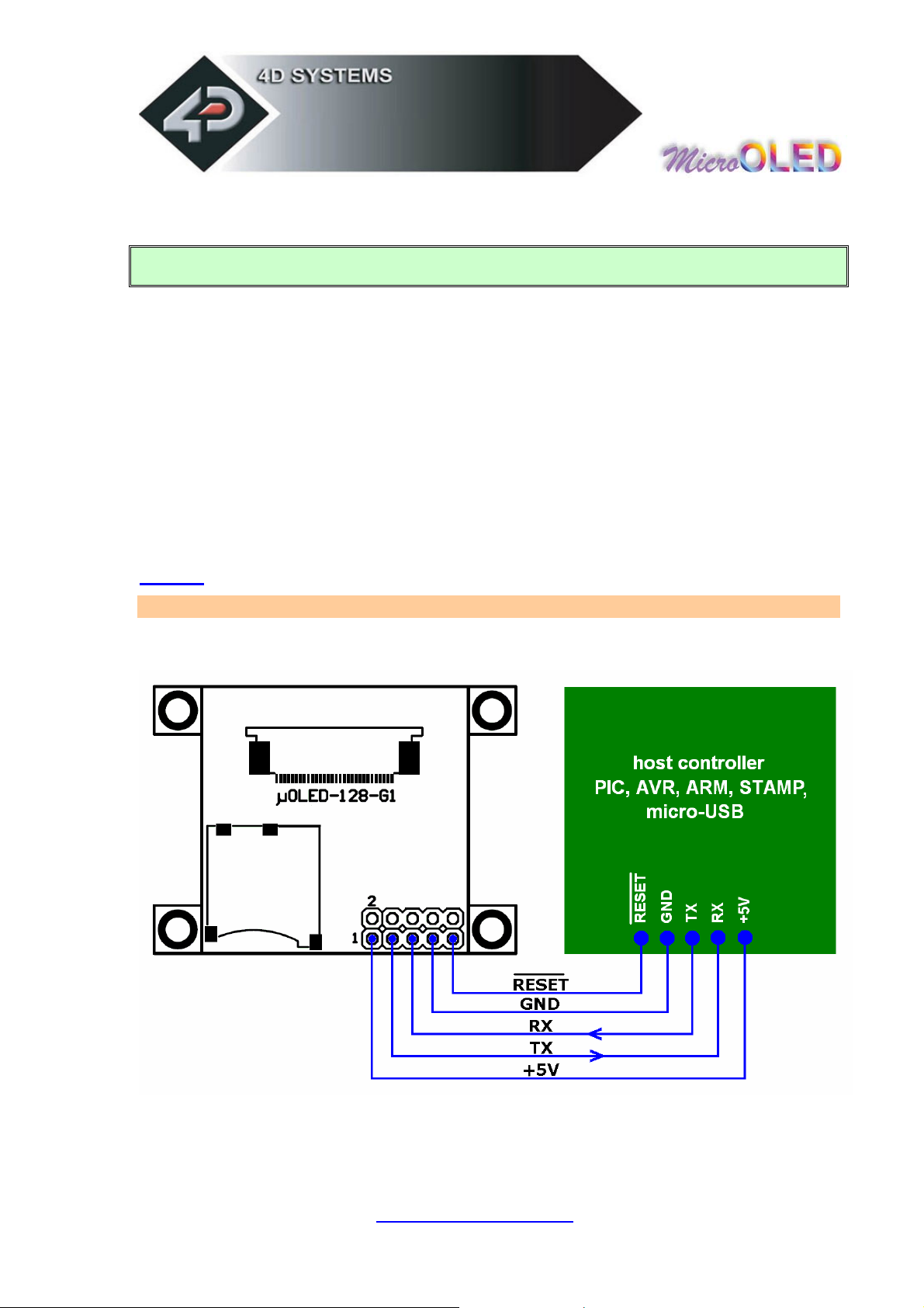
Serial Platform : host microcontroller interface
Pin Function Description
1 VIN
3 TX
5 RX
7 GND
9 RESET
These are the most commonly used pins for µOLED-128-G1 to
host microcontroller interface.
www.4dsystems.com.au
µ E G1
OL D-128-
63
Page 64

Serial/4DGL Platform : micro-USB interface
Pin Function Description
1 VIN
3 TX
5 RX
7 GND
9
RESET
For Serial and 4DGL Platform PmmC upgrades or platform change
overs as well as for 4DGL user code downloads, the µOLED-128-
G1 needs to be interfaced to a PC. This is best achieved via any
one of the 4D range of micro-USB (USB to Serial) converter
modules. The software tools offered by 4D seamlessly transfer the
required data to the µOLED-128-G1 via the micro-USB interface.
Please observe the correct row on the 10 pin header when plugging
the micro-USB module.
www.4dsystems.com.au
µ E G1
OL D-128-
64
Page 65

www.4dsystems.com.au
µ E G1
OL D-128-
65
Page 66

5 Personality-module-micro Code (PmmC)
One of the important features of any intelligent 4D module is the ability
to upload its onboard GOLDELOX/PICASO processor with a micro-Code
firmware that facilitates platform upgrades or platform change overs. This
is referred to as the Personality-module-micro-Code (PmmC). The
benefits of this are:
• The module can be easily upgraded by the user at any time with
PmmC files as future enhancements or bug fixes are made. This
allows the user to benefit from those latest features and releases.
• Allows the user to upload a new Operating System to change the
device from a serial command driven platform into a high level
language platform such as 4DGL.
The latest PmmC files for both the Serial and 4DGL platforms are
available for download from the links provided on the µOLED-128-G1
product web page.
To assist the user in downloading the PmmC file into the module,
appropriate software tools are required. The PmmC Loader is a PC
Windows based software tool to upload the GOLDELOX and PICASO
processor based modules with PmmC system files.
The latest version of “PmmCLoader” PC software tool can be
downloaded from:
www.4dsystems.com.au/downloads/PmmC-Loader/Software/Windows/
and the User Guide can be found here:
www.4dsystems.com.au/downloads/PmmC-Loader/Docs/Pdf/
www.4dsystems.com.au
µ E G1
OL D-128-
66
Page 67

6 Circuit Diagram
www.4dsystems.com.au
µ E G1
OL D-128-
67
Page 68

7 Mechanical Details
The module thickness is 6.3mm (not including header pins)
www.4dsystems.com.au
µ E G1
OL D-128-
68
Page 69

8 Specifications & Ratings
Symbol Characteristic Min Typ Max Units
Vdd Supply voltage 3.6* 5.0 6.0 Volts
I Current 10 40 115 mA
Top Operating temp -10 -- 70 deg C
Tsto Storage temp -30 -- 80 deg C
Tpu Power-up delay 1000 -- -- msec
L Luminance 80 100 -- Cd/m2
VA Viewing Angle 160 170 179 degrees
Cr Contrast Ratio 5000:1 10000:1 -- --
Vtx TX pin Voltage Out 0.8 3.0 3.3 Volts
0 2.4 5.0 Vrx RX pin Voltage In Volts
Operational Life Time
LTop
*NOTE! Due to characteristics of certain micro-SD memory cards, the module
may require supply voltages greater than 4.0 Volts when used with a micro-SD
memory card.
@30% power 10,000 15,000 20,000 hours
to half intensity
Current Contrast (section 2.2.22) Notes
13.5mA High, value = 15dec All Pixels OFF (black screen)
115.0mA High, value = 15dec All Pixels ON (white screen)
40.0mA High, value = 15dec Average Usage (screen has text and graphics)
13.5mA Medium, value = 08dec All Pixels OFF (b lack screen)
110.0mA Medium, value = 08dec All Pixels ON (white screen)
32.0mA Medium, value = 08dec Average Usage (screen has text and graphics)
13.5mA Low, value = 00dec All Pixels OFF (black screen)
41.0mA Low, value = 00dec All Pixels ON (white screen)
18.0mA Low, value = 00dec Average Usage (screen has text and graphics)
10.3mA Low, Medium, High Screen Power Down Command
www.4dsystems.com.au
µ E G1
OL D-128-
69
Page 70

9 Precautions
Avoid having a White Background. The more pixels that are lit up,
the more the display module will consume current. A full white
screen will have the highest power consumption.
Avoid displaying objects or text on White Backgrounds. This will
cause a smearing effect which is inherent to all PMOLED displays.
Instead try a shaded mixed colour as the background or better still
a black background. Ideally have mixed coloured objects/text/icons
on a black background.
Avoid having to display the same image/object on the screen for
lengthy periods of time. This will cause a burn-in which is a
common problem with all types of display technologies. Blank the
screen after a while or dim it very low by adjusting the contrast.
This can be achieved via the “OLED Display Control Functions”
command (section 2.2.22). Better still; implement a screen saver
feature by using the scroll screen command.
Observe the Power-Down procedure (section 2.2.22). The module
automatically takes care of the proper Power-Up sequence.
www.4dsystems.com.au
µ E G1
OL D-128-
70
Page 71
10 Related Products and Software Tools
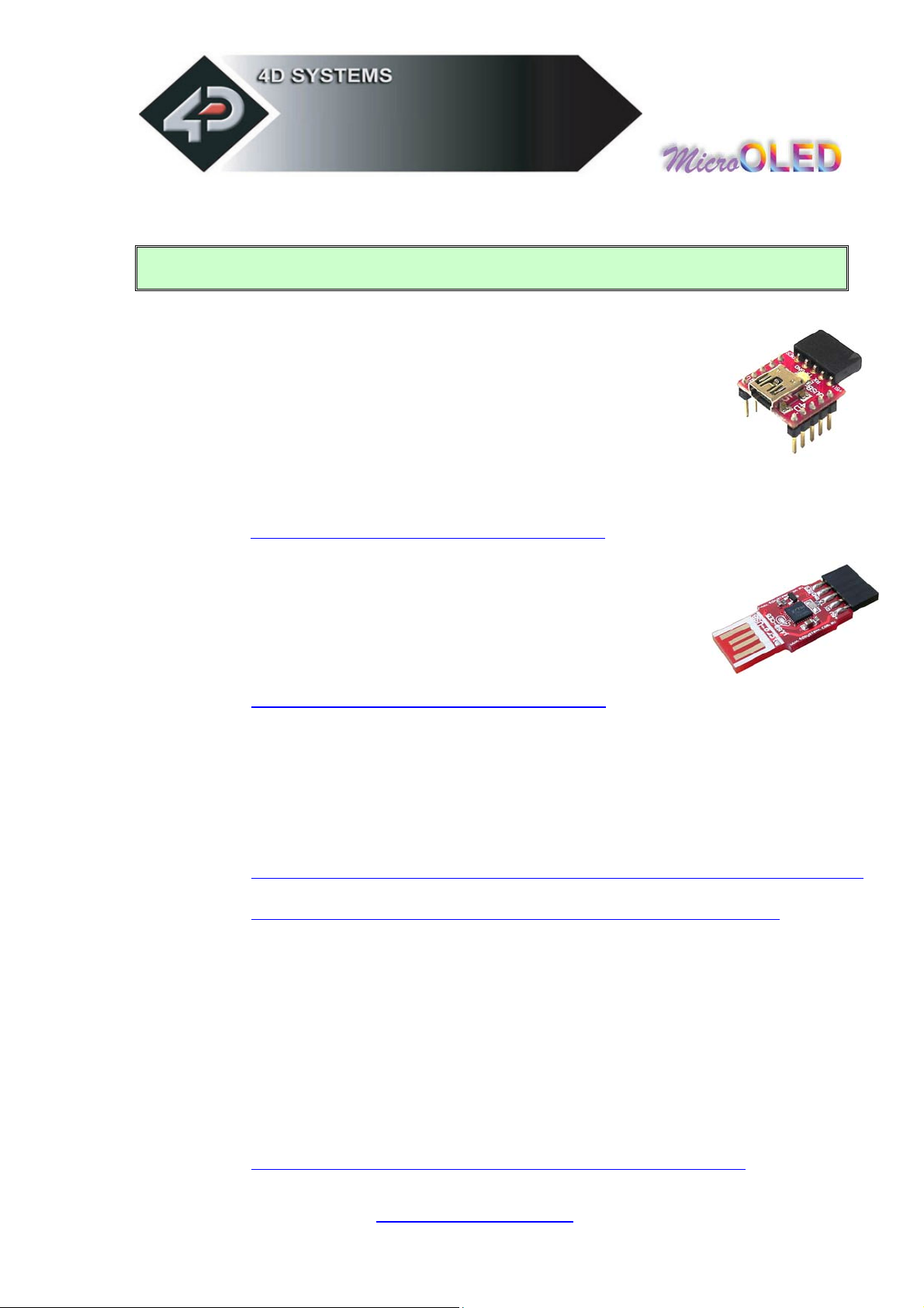
µUSB-MB5
o micro-USB module, USB to Serial Bridge, Silabs CP2102
o Standard USB miniB connector
o 10 pin header provides the following signals:
5V, 3.3V, GND, Tx, Rx, Suspend,
DTR, CTS, RTS, GND
o 5 Volts supply @ 500mA, 3.3 Volts supply @ 100mA
o Additional flow control signals, DTR, CTS, RTS
o Available with an additional 5 pin header for the µOLED interface
www.4dsystems.com.au/prod.php?id=18
µUSB-CE5
o micro-USB module, USB to Serial Bridge, FTDI Chipset
o Plugs directly into USB port
o 5 pin header provides the fo llowing signals:
5V, Rx, Tx, GND, Reset
o 5 Volts supply @ 500mA
www.4dsystems.com.au/prod.php?id=19
PmmC Files
o The latest PmmC system files for the module can be downloaded from
the links available on the µOLED-128-G1 product page:
PmmC Loader (free software tool)
o Latest version of PmmC-Loader software tool can be downloaded from:
www.4dsystems.com.au/downloads/PmmC-Loader/Software/Windows/
and the User Guide can be found here:
www.4dsystems.com.au/downloads/PmmC-Loader/Docs/Pdf/
4DGL Workshop (free software tool)
o This is the IDE plus editor plus compiler for all 4DGL user
applications. Everything is provided in a single package to write,
compile and download 4DGL application code into the target
module.
4D Graphics Composer (free software tool)
o A PC based software tool that assists downloading of images,
animations and movie clips into the micro-SD memory card which can
then be recalled and used on the serial and 4DGL platforms.
www.4dsystems.com.au/downloads/Graphics_Composer/
www.4dsystems.com.au
µ E G1
OL D-128-
71
 Loading...