

4D systems GEN4-4DCAPE-50, GEN4-4DCAPE-43T, GEN4-4DCAPE-SB, GEN4-4DCAPE-43, GEN4-4DCAPE-50CT Datasheet
...Page 1

Uncontrolled Copy when printed or downloaded.
Please refer to the 4D Systems website for the latest Revision of this document
Gen4 LCD CAPE Range
4.3”, 5.0” and 7.0” LCD CAPE’s
For the Beagle Bone Black
GEN4-4DCAPE-43 (4.3” Non-Touch)
GEN4-4DCAPE-43T (4.3” Resistive Touch)
GEN4-4DCAPE-43CT (4.3” Capacitive Touch)
GEN4-4DCAPE-50 (5.0” Non-Touch)
GEN4-4DCAPE-50T (5.0” Resistive Touch)
GEN4-4DCAPE-50CT (5.0” Capacitive Touch)
GEN4-4DCAPE-70 (7.0” Non-Touch)
GEN4-4DCAPE-70T (7.0” Resistive Touch)
GEN4-4DCAPE-70CT (7.0” Capacitive Touch)
GEN4-4DCAPE-xxx-SB (Super Bright, All sizes/Touch)
Document Date: 8th March 2017
Document Revision: 1.0
D
ATASHEET
Page 2

Contents
1. Description ............................................................................................................................. 4
2. Features ................................................................................................................................. 4
3. Getting Started ....................................................................................................................... 5
3.1. Requirements ......................................................................................................................................... 5
3.2. How to use the GEN4 LCD CAPE ............................................................................................................. 5
3.3. Changing the brightness (Debian) .......................................................................................................... 5
3.4. Calibrating resistive touch (Debian) ....................................................................................................... 6
4. EEPROM Details ...................................................................................................................... 6
5. Hardware Drivers ................................................................................................................... 6
6. Display Precautions ................................................................................................................ 6
7. Optional Button Board ............................................................................................................ 7
8. Power Source for 4D CAPE ...................................................................................................... 7
9. Display Module Part Numbers................................................................................................. 7
10. Cover Lens Bezel – Tape Spec ................................................................................................ 7
11. Standard FFC cable specifications .......................................................................................... 8
12. Software / Driver Disclaimer ................................................................................................. 8
13. Notes ................................................................................................................................... 8
14. Schematic Diagram (4D CAPE) ............................................................................................... 9
15. Schematic Diagram (4DCAPE Adaptor) ................................................................................. 10
16. Schematic Diagram (4DCAPE Button Board – OPTIONAL) ..................................................... 11
17. Mechanical Details – 4.3” (Non-Touch & Resistive Touch) .................................................... 12
18. Mechanical Details – 4.3” (Capacitive Touch) ....................................................................... 13
19. Mechanical Details – 5.0” (Non-Touch & Resistive Touch) .................................................... 14
20. Mechanical Details – 5.0” (Capacitive Touch) ....................................................................... 15
21. Mechanical Details – 7.0” (Non-Touch & Resistive Touch) .................................................... 16
22. Mechanical Details – 7.0” (Capacitive Touch) ....................................................................... 17
23. Mechanical Details (4DCAPE Adaptor) ................................................................................. 18
24. Mechanical Details (4DCAPE Button Board – OPTIONAL – BUILT ON REQUEST ONLY) ............ 19
25. Specifications ..................................................................................................................... 20
Page 3

26. Hardware Revision History (4D CAPE) .................................................................................. 22
27. Hardware Revision History (4D CAPE Adaptor) .................................................................... 22
28. Ordering Information .......................................................................................................... 23
29. Legal Notice ........................................................................................................................ 24
30. Contact Information............................................................................................................ 24
Page 4
4D SYSTEMS GEN4 LCD CAPES – BEAGLE BONE BLACK
© 2017 4D SYSTEMS Page 4 of 24 www.4dsystems.com.au
1. Description
The gen4 LCD CAPE range is specifically designed for
the Beagle Bone Black* (BBB), and provides a 4.3”,
5.0” or 7.0” primary display for the BBB for direct
user interaction and information display.
Available in both Resistive Touch (GEN4-4DCAPExxT), Capacitive Touch (GEN4-4DCAPE-xxCT) and
non-touch (GEN4-4DCAPE-xx) via special request –
the non-touch version may be subject to MOQ.
(xx refers to 43, 50 and 70 accordingly)
The 4DCAPE is not compatible with the previous
Beagle Bone (Beagle Bone White), and can only be
used with the Beagle Bone Black.
The 4DCAPE features an on-board Microchip
AR1021 resistive touch controller (Resistive Touch
version only), which talks to the BBB over I2C. This
enables a robust and reliable resistive touch
platform, compared to previous 4DCAPE models
which used the BBB’s analog inputs, which were
prone to external noise and open source software.
The Capacitive Touch version utilises a Focaltech
capacitive touch controller, which also
communicates over I2C.
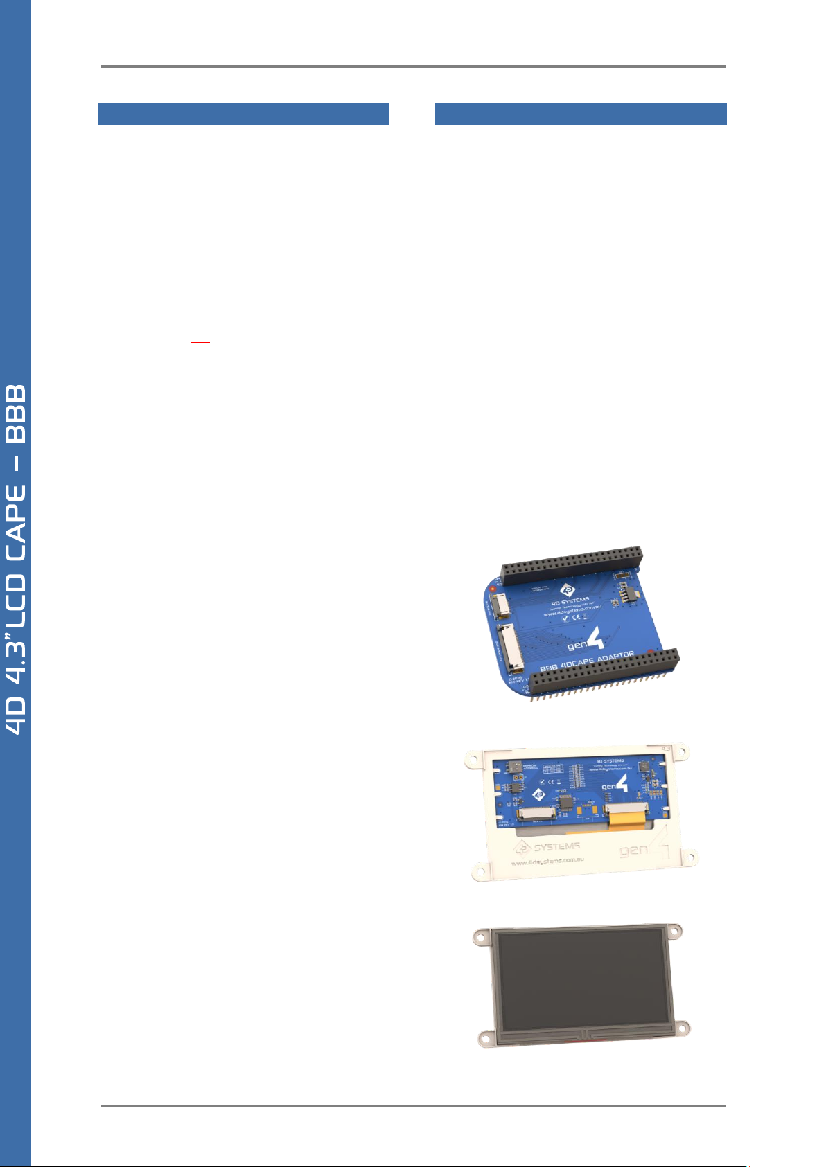
The Beagle Bone Black connects directly on to an
adaptor CAPE, which then connects to the display
module using a 30 way FFC ribbon cable, enabling
multiple mounting options. Everything the LCD
CAPE requires such as power and display signals are
provided from the BBB directly, via the Adaptor and
FFC ribbon cable.
The gen4 LCD CAPE features an optional push
buttons connector, providing capability for an
external button board. Please contact Sales
regarding this item, it is a special-order item only.
Mounting of the 4DCAPE is achieved with the 4x
4mm mounting holes present on the Display
Module (Resistive and Non-Touch), enabling
standard screws to fasten the GEN4 4DCAPE as
required, or via the adhesive supplies on the Cover
Lens Bezel which is part of the Capacitive Touch
version.
Note (*): The Beaglebone, Beaglebone Black and
Beagleboard remains the property of
beaglebone.org. All references to the words
Beaglebone, Beaglebone Black, Beagleboard are
licensed under a Creative Commons AttributionShare Alike 3.0 license.
2. Features
• 4.3”, 5.0” and 7.0” TFT LCD CAPE options for the
Beagle Bone Black
• Available in 3 models, Resistive Touch (GEN4-
4DCAPE-xxT), Capacitive Touch (GEN4-4DCAPExxCT) and Non-Touch (GEN4-4DCAPE-xx) where
xx is 43, 50 and 70.
• 480x272 Resolution 4.3” TFT LCD Display, or
800x480 Resolution 5.0” and 7.0” TFT LCD
Display
• 7 optional push buttons via external button
board is available on request, enabling LEFT,
RIGHT, UP, DOWN, ENTER, RESET and POWER
functionality. This push button board is only
available on request and is made to order.
• EEPROM CAPE ID selection via DIP switch
• 4x 4.0mm Mounting holes on Non-Touch and
Resistive Touch modules, or via adhesive for
Capacitive Touch model.
• RoHS and CE Compliant.
GEN4 4D CAPE Adaptor
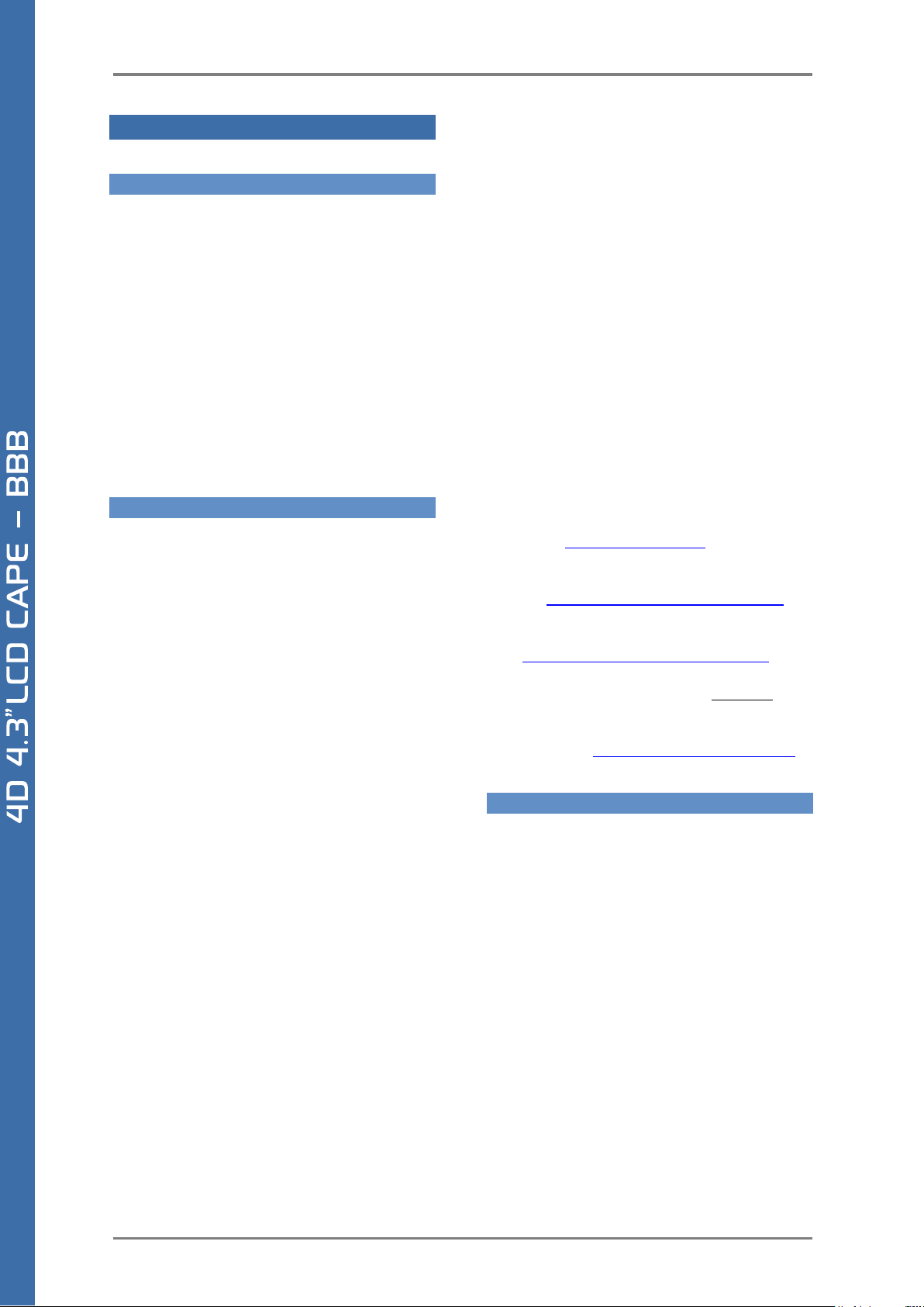
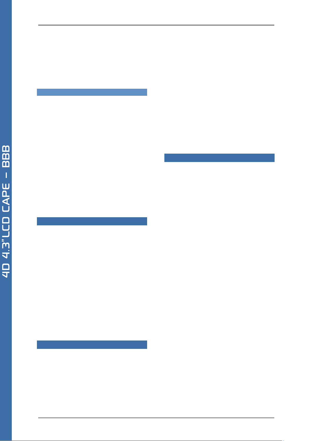
GEN4 4D CAPE 4.3” Resistive Touch Display
Page 5
4D SYSTEMS GEN4 LCD CAPES – BEAGLE BONE BLACK
© 2017 4D SYSTEMS Page 5 of 24 www.4dsystems.com.au
3. Getting Started
3.1. Requirements
The gen4 LCD CAPE’s are designed to work with the
Debian Operating System supplied for the Beagle
Bone Black. It could however be adapted to work on
other distributions by the User.
The Requirements for use are:
• GEN4 LCD Cape + Adaptor + FFC Cable
• Beagle Bone Black (BBB) with suitable
distribution loaded
• 5V DC Supply suitable for the Beagle Bone Black
(using DC Jack), recommended 2A @ 5V.
• A Stylus is recommended for accurate touch,
however is not required.
3.2. How to use the GEN4 LCD CAPE
The following steps should be all that is required to
use the GEN4 4DCAPE:
1. Connect the 4DCAPE Adaptor to the Beagle
Bone Black while the Beagle Bone Black is not
powered.
2. Connect the 30 way FFC cable to the 4D CAPE
Adaptor, and to the 4DCAPE Display. The 30
way FFC connectors are ‘Upper Contact’
meaning the blue stiffener on the FFC cable
should be against the PCB, with the metal pads
on the cable facing upward.
3. If using with other capes on your BBB, ensure
the 4DCAPE is not conflicting pin wise to any
other cape installed.
4. Ensure the EEPROM ID Jumper on the CAPE is
set to a different EEPROM ID to any other
capes.
5. Ensure your Beagle Bone Black is loaded with a
suitable Linux distribution which is compatible
with 4D Systems 4DCAPE’s. Debian is the
distribution shipping with current BBB boards
now, and can be installed onto older BBB’s. If
the distribution you wish to use is not
supporting 4D Systems 4DCAPE’s by default,
the supplied source files can be used, please
refer to our Product Page.
6. Connect a 5V Supply to the DC Jack of the
Beagle Bone Black. It is recommended to use a
2A supply to ensure sufficient supply. By
default, the 4DCAPE requires power via the DC
Jack, as the on-board power management of
the BBB may be overloaded depending on
other systems installed. So, the USB jack will
not supply power to the 4D CAPE unless the
Solder Bridge jumper on the top of the 4DCAPE
Adaptor board, is cut and resoldered.
(Discussed further in a later section)
7. Once power is connected, something should be
displayed on the 4DCAPE a few moments after
it has started to boot. Each distribution will
behave differently and require different input
from the User. It is recommended to have a
keyboard attached while setting the system up,
as login details etc may be required. Some
distributions may prompt for LCD calibration,
while others may prompt for
Username/Password.
For support of the BBB and various distributions,
please seek support from the respective websites
associated with the BBB itself or the distributions –
See Section 5.
A good place to start for information and support
regarding the BBB and various distributions
available, is www.beagleboard.org
This website details the latest firmware images for
the BBB: http://beagleboard.org/latest-images
This website details how to get started with the
BBB: http://beagleboard.org/getting-started
For support regarding the 4DCAPE hardware itself,
please go to the 4D Systems website and either
contact Support directly via a Ticket, or use the 4D
Systems Forum. http://forum.4dsystems.com.au
3.3. Changing the brightness (Debian)
It is possible to change the backlight brightness as
the backlight is PWM controlled.
Please note, these instructions may become
obsolete as new versions of Debian are released, or
if different distributions are used.
One method is to SSH into the Beaglebone Black
from your PC, and set the backlight value that way.
Note this does not persist over restarts, so this
would need to be entered into a startup script if the
setting is required to be set each startup.
At the command prompt, type the following:
# sudo su
# cd /sys/class/backlight/backlight
# echo 50 > brightness
Page 6
4D SYSTEMS GEN4 LCD CAPES – BEAGLE BONE BLACK
© 2017 4D SYSTEMS Page 6 of 24 www.4dsystems.com.au
Where 50 represents 50%, this can be changed to
any number from 0 to 100 as required.
The exact path may vary with distributions, so
check the /sys/class/backlight path to see what
backlight file exists.
3.4. Calibrating resistive touch (Debian)
When a distribution is used for the first time with a
4DCAPE, often a LCD calibration application will
start automatically. However, depending on the
distribution in use, this may or may not happen.
Some distributions may not even come with a
calibration application loaded.
For ones that do have the calibration program
loaded by default, and if the calibration is input
incorrectly and it is required to be set again, it can
be generally be started from the ‘Start’ menu.
Note, this may change as newer distributions
become available, or if different distributions are
used, so these instructions may become obsolete or
inaccurate.
4. EEPROM Details
On the 4DCAPE Display Module there is an EEPROM
which the BBB reads and uses to determine which
drivers/modules to load based on overlay files
which exist on that specific distribution.
There is a DIP Switch on the top left corner of the
4DCAPE Display Module, which allow the EEPROM
ID to be set to 4 different values, so 4 different
CAPES can be added to a single BBB if required. Only
1 LCD CAPE can be installed at once however.
The EEPROM ID will change from 0x57 when both
switches are OFF, 0x56 when the left-hand side (A0)
is ON, 0x55 when the right-hand side (A1) is ON, and
0x54 when both are ON.
5. Hardware Drivers
The 4DCAPE features the AR1021 resistive touch IC,
made by Microchip, and a driver is supplied for this
by 4D Systems for use with Linux systems such as
Debian. Communications to the AR1021 are via I2C,
specifically utilising the I2C #1 channel on the BBB.
Please refer to the Schematic Diagram for more
information about its connections.
The 4DCAPE also features the TI TPS61165 backlight
drive IC, which implements a 1-wire
communications protocol between the BBB and the
Driver IC, enabling software commands to be sent
from the BBB rather than PWM signals, to vary the
backlight brightness. This results in lower noise and
a more stable backlight system. A Driver for this is
supplied by 4D Systems for use with Linux system
such as Debian.
The Capacitive Touch version of the 4DCAPE
features a Focaltech Capacitive Touch controller
built into the display. This communicates to the BBB
using the I2C #1 channel. A Driver for this is supplied
by 4D Systems for use with Linux system such as
Debian.
6. Display Precautions
• Avoid having to display the same image/object on
the screen for lengthy periods of time. This will
cause a burn-in which is a common problem with all
types of display technologies. Blank the screen after
a while or dim it very low by adjusting the contrast.
Better still; implement a screen saver feature.
• Moisture and water can damage the display.
Moisture on the surface of a powered display will
cause the electrodes to corrode. Wipe off any
moisture gently or let the display dry before usage.
• Dirt from fingerprint oil and fat can easily stain the
surface of the display. Gently wipe off any stains
with a soft lint-free cloth.
• The performance of the display will degrade
under high temperature and humidity. Avoid such
conditions when storing.
• Do not tamper with the display flex cable that is
connected to the control board. This may affect the
connection between the display and the driving
circuitry and cause failure. Under no circumstances
should the display flex be disconnected from the
PCB and power applied to the PCB, as this could
result in instant failure of the CAPE.
• Displays are susceptible to mechanical shock and
any force exerted on the module may result in
deformed zebra stripes, a cracked display cell and
broken backlight
• Always use the mounting holes (where applicable)
on the module to mount the display.
Page 7
4D SYSTEMS GEN4 LCD CAPES – BEAGLE BONE BLACK
© 2017 4D SYSTEMS Page 7 of 24 www.4dsystems.com.au
7. Optional Button Board
The 4DCAPE has the option to use an external
button board, for actions such as up, down, left,
right, enter/return, power and reset, or as required
by the User.
Alternatively, any momentary push buttons can be
attached, as they are simply a connection between
a GPIO and GND to form the button press
connection. 4D Systems provides a button board
which can be used if required, and supplied/sold on
request. It is not offered as part of the module as
standard.
The 4D Button Board for the 4DCAPE is a small PCB
with a row of 7 momentary push buttons on the
front, and a 10 way FFC connector designed for a
10-way ribbon cable to attach to, and then connect
to the 4DCAPE Adaptor board.
The 10 way FFC connectors for the 4D Button Board
are Bottom Contact, meaning the terminals need to
be towards the PCB, and the stiffener needs to be
facing upwards (opposite to the main 30 way FFC
cable to the display).
8. Power Source for 4D CAPE
The 4DCAPE power source comes from the BBB, via
the 4D CAPE Adaptor board which plugs on top of
the BBB itself.
The Adaptor board taps into the VDD_5V bus power
on the BBB, which is connected to the DC Barrel
Jack on the BBB. It will not receive power when the
BBB is powered from USB, as the USB power goes
via the BBB power management IC, which then is
supplied on the SYS_5V bus.
It has been designed this way by default as the
SYS_5V system has finite capabilities, and
depending what else the BBB is doing and what
other CAPES/Devices are connected, there may not
be sufficient power left to supply the 4DCAPE. Also,
if a SB (Super Bright) version of the 4DCAPE is used,
it is very likely the USB power management system
would not supply enough power even if nothing
else was connected. It however is possible to
modify the 4DCAPE Adaptor board to use the
SYS_5V bus, if required.
On the top of the 4DCAPE Adaptor is a Solder
Jumper, which has 3 pads. By default, there is a
track connecting the centre pad to the side marked
VDD_5V. If SYS_5V is required instead, then this
VDD_5V track must be cut between these 2 pads,
and a solder blob be added instead between the
centre pad and the pad marked SYS_5V. DO NOT
have both sides connected to the centre pad at
once, else your BBB may be damaged.
A sharp craft knife, a soldering iron and solder are
required ideally for this modification.
Take care when doing this modification, as
warranty claims will not apply due to damage of the
product while undertaking this modification.
9. Display Module Part Numbers
The following is a breakdown on the part numbers
and what they mean.
Example:
gen4-4DCAPE-70CT-SB
gen4 - gen4 Display Range
4DCAPE - Display Family
70 - Display size (7.0”)
T - Resistive Touch.
CT - Capacitive Touch (with CLB)
SB - Super Bright Display
• For part numbers which do not include T or CT,
these are non-touch variants.
• Cover Lens Bezels (CLB) are glass fronts for the
display module with overhanging edges, which
allow the display module to be mounted
directly into a panel using special adhesive on
the overhanging glass. These are available for
Capacitive Touch only.
10. Cover Lens Bezel – Tape Spec
The perimeter of the CLB display modules features
double-sided adhesive tape, designed to stick
directly onto a panel, enclosure, box etc without
the need for any mounting screws or hardware.
The tape used is 3M 9495LE tape, which uses the
well-known and strong 3M 300LSE adhesive.
The double-sided adhesive has a thickness of
0.17mm once the backing has been removed.
More information on this adhesive can be found on
the 3M website.
http://multimedia.3m.com/mws/media/771683O/
3mtm-double-coated-tapes-9474le-9495le.pdf
Page 8
4D SYSTEMS GEN4 LCD CAPES – BEAGLE BONE BLACK
© 2017 4D SYSTEMS Page 8 of 24 www.4dsystems.com.au
11. Standard FFC cable specifications
Between the gen4-4DCAPE-Adaptor and the gen4-CAPE Display Module, the following FFC cable is supplied:
30 Pin Flexible Flat Cable, 150mm Long, 0.5mm (0.02") pitch
Cable Type: AWM 20624 80C 60V VW-1
Heat Resistance 80 Degrees Celsius
Connections on the opposite side at each end (Type B)
Between the gen4-4DCAPE-Adaptor and the gen4-4DCAPE Button Board (when purchased via Sales Dept), the
following FFC cable is supplied:
10 Pin Flexible Flat Cable, 150mm Long, 0.5mm (0.02") pitch
Cable Type: AWM 20624 80C 60V VW-1
Heat Resistance 80 Degrees Celsius
Connections on the opposite side at each end (Type B)
12. Software / Driver Disclaimer
4D Systems has developed this 4DCAPE for the Beaglebone Black. 4D Systems does NOT support any software
associated with the BBB itself, as 4D Systems is not involved with the development or support of the BBB
Operating Systems. It is up to the user to determine which distributions are used on the BBB, and therefore
which are compatible with this CAPE. 4D Systems will supply the source code for the 4DCAPE, which is installed
on the Debian Distribution for the BBB by default, however the source can be used if Users wish to use another
operating system. It will however be up to the User to get this operational. Assistance can be provided on our
Forum. http://forum.4dsystems.com.au
4D Systems is not responsible for issues regarding software or drivers associated with the BBB and the
compatibility with this product. Community software support is available via resources at
www.beaglebone.org/discuss
13. Notes
__________________________________________________________________________________________
__________________________________________________________________________________________
__________________________________________________________________________________________
__________________________________________________________________________________________
__________________________________________________________________________________________
__________________________________________________________________________________________
__________________________________________________________________________________________
__________________________________________________________________________________________
__________________________________________________________________________________________
__________________________________________________________________________________________
__________________________________________________________________________________________
__________________________________________________________________________________________
__________________________________________________________________________________________
__________________________________________________________________________________________
__________________________________________________________________________________________
__________________________________________________________________________________________
__________________________________________________________________________________________
__________________________________________________________________________________________
__________________________________________________________________________________________
__________________________________________________________________________________________
__________________________________________________________________________________________
Page 9

4D SYSTEMS GEN4 LCD CAPES – BEAGLE BONE BLACK
© 2017 4D SYSTEMS Page 9 of 24 www.4dsystems.com.au
14. Schematic Diagram (4D CAPE)
Page 10

4D SYSTEMS GEN4 LCD CAPES – BEAGLE BONE BLACK
© 2017 4D SYSTEMS Page 10 of 24 www.4dsystems.com.au
15. Schematic Diagram (4DCAPE Adaptor)
Page 11

4D SYSTEMS GEN4 LCD CAPES – BEAGLE BONE BLACK
© 2017 4D SYSTEMS Page 11 of 24 www.4dsystems.com.au
16. Schematic Diagram (4DCAPE Button Board – OPTIONAL)
Page 12

4D SYSTEMS GEN4 LCD CAPES – BEAGLE BONE BLACK
© 2017 4D SYSTEMS Page 12 of 24 www.4dsystems.com.au
17. Mechanical Details – 4.3” (Non-Touch & Resistive Touch)
Page 13

4D SYSTEMS GEN4 LCD CAPES – BEAGLE BONE BLACK
© 2017 4D SYSTEMS Page 13 of 24 www.4dsystems.com.au
18. Mechanical Details – 4.3” (Capacitive Touch)
Page 14

4D SYSTEMS GEN4 LCD CAPES – BEAGLE BONE BLACK
© 2017 4D SYSTEMS Page 14 of 24 www.4dsystems.com.au
19. Mechanical Details – 5.0” (Non-Touch & Resistive Touch)
Page 15

4D SYSTEMS GEN4 LCD CAPES – BEAGLE BONE BLACK
© 2017 4D SYSTEMS Page 15 of 24 www.4dsystems.com.au
20. Mechanical Details – 5.0” (Capacitive Touch)
Page 16

4D SYSTEMS GEN4 LCD CAPES – BEAGLE BONE BLACK
© 2017 4D SYSTEMS Page 16 of 24 www.4dsystems.com.au
21. Mechanical Details – 7.0” (Non-Touch & Resistive Touch)
Page 17

4D SYSTEMS GEN4 LCD CAPES – BEAGLE BONE BLACK
© 2017 4D SYSTEMS Page 17 of 24 www.4dsystems.com.au
22. Mechanical Details – 7.0” (Capacitive Touch)
Page 18

4D SYSTEMS GEN4 LCD CAPES – BEAGLE BONE BLACK
© 2017 4D SYSTEMS Page 18 of 24 www.4dsystems.com.au
23. Mechanical Details (4DCAPE Adaptor)
Page 19

4D SYSTEMS GEN4 LCD CAPES – BEAGLE BONE BLACK
© 2017 4D SYSTEMS Page 19 of 24 www.4dsystems.com.au
24. Mechanical Details (4DCAPE Button Board – OPTIONAL – BUILT ON REQUEST ONLY)
Page 20

4D SYSTEMS GEN4 LCD CAPES – BEAGLE BONE BLACK
© 2017 4D SYSTEMS Page 20 of 24 www.4dsystems.com.au
25. Specifications
ABSOLUTE MAXIMUM RATINGS
Operating ambient temperature ................................................................................................... -20°C to +70°C
Storage temperature .......................................................................................................................... -30°C +80°C
NOTE: Stresses above those listed here may cause permanent damage to the device. This is a stress rating only
and functional operation of the device at those or any other conditions above those indicated in the
recommended operation listings of this specification is not implied. Exposure to maximum rating conditions for
extended periods may affect device reliability.
GLOBAL CHARACTERISTICS BASED ON OPERATING CONDITIONS
Parameter
Conditions
Min
Typ
Max
Units
Supply Current
(5V bus of BBB)
(INCLUDES POWER BBB
USES ALSO – NOTE)
gen4-4DCAPE-43 (Max Brightness)
--
590
--
mA
gen4-4DCAPE-43T (Max Brightness)
--
600
--
mA
gen4-4DCAPE-43CT (Max Brightness)
--
620
--
mA
gen4-4DCAPE-43-SB (Max Brightness)
--
690
--
mA
gen4-4DCAPE-43T-SB (Max Brightness)
--
700
--
mA
gen4-4DCAPE-43CT-SB (Max Brightness)
--
720
--
mA
gen4-4DCAPE-50 (Max Brightness)
--
700
--
mA
gen4-4DCAPE-50T (Max Brightness)
--
710
--
mA
gen4-4DCAPE-50CT (Max Brightness)
--
720
--
mA
gen4-4DCAPE-50-SB (Max Brightness)
--
830
--
mA
gen4-4DCAPE-50T-SB (Max Brightness)
--
840
--
mA
gen4-4DCAPE-50CT-SB (Max Brightness)
--
850
--
mA
gen4-4DCAPE-70 (Max Brightness)
--
980
--
mA
gen4-4DCAPE-70T (Max Brightness)
--
990
--
mA
gen4-4DCAPE-70CT (Max Brightness)
--
1100
--
mA
gen4-4DCAPE-70-SB (Max Brightness)
--
1190
--
mA
gen4-4DCAPE-70T-SB (Max Brightness)
--
1200
--
mA
gen4-4DCAPE-70CT-SB (Max Brightness)
--
1220
--
mA
Display Endurance
Hours of operation, measured to
when display is 50% original
brightness
30000
--
--
H
Touch Screen Endurance
(Resistive Touch)
Number of touches/hits with a
12.5mm tip at a rate of 2x per
second with 250gf force
--
1M
--
Touches
Slide stylus on screen, 100gf force,
60mm/s speed with a 0.8mm
polyacetal tip stylus pen
--
100K
--
Slides
Touch Screen Transparency
Resistive Touch
82
--
--
%
Capacitive Touch
90
--
--
%
Touch Screen Operational
Force (Resistive Touch)
Only use Finger or Stylus, do not
use anything sharp or metal
20
--
100
Gf
CLB Hardness
(Capacitive Touch)
Cover Lens Bezel Glass Hardness
-- 6 --
H
Page 21

4D SYSTEMS GEN4 LCD CAPES – BEAGLE BONE BLACK
© 2017 4D SYSTEMS Page 21 of 24 www.4dsystems.com.au
LCD DISPLAY INFORMATION
Parameter
Conditions
Specification
Display Type TFT Transmissive LCD
Display Sizes
4.3”, 5.0” or 7.0” Diagonal
Display Resolution
480 x 272 (Landscape Viewing) – 4.3”
800 x 480 (Landscape Viewing) – 5” & 7”
Display Brightness
gen4-4DCAPE-43 (Max Brightness)
500 cd/m2
gen4-4DCAPE-43T (Max Brightness)
400 cd/m2
gen4-4DCAPE-43CT (Max Brightness)
475 cd/m2
gen4-4DCAPE-43-SB (Max Brightness)
1020 cd/m2
gen4-4DCAPE-43T-SB (Max Brightness)
825 cd/m2
gen4-4DCAPE-43CT-SB (Max Brightness)
880 cd/m2
gen4-4DCAPE-50 (Max Brightness)
500 cd/m2
gen4-4DCAPE-50T (Max Brightness)
400 cd/m2
gen4-4DCAPE-50CT (Max Brightness)
475 cd/m2
gen4-4DCAPE-50-SB (Max Brightness)
820 cd/m2
gen4-4DCAPE-50T-SB (Max Brightness)
650 cd/m2
gen4-4DCAPE-50CT-SB (Max Brightness)
705 cd/m2
gen4-4DCAPE-70 (Max Brightness)
500 cd/m2
gen4-4DCAPE-70T (Max Brightness)
400 cd/m2
gen4-4DCAPE-70CT (Max Brightness)
475 cd/m2
gen4-4DCAPE-70-SB (Max Brightness)
844 cd/m2
gen4-4DCAPE-70T-SB (Max Brightness)
679 cd/m2
gen4-4DCAPE-70CT-SB (Max Brightness)
758 cd/m2
Display Contrast Ratio
Typical
500:1
Display Viewing Angles
Above Centre
70 Degrees
Below Centre
60 Degrees
Left of Centre
70 Degrees
Right of Centre
70 Degrees
Display Viewing Direction
12 o’clock Display
(Optimal viewing is from above when in
Landscape/Wide mode)
Display Backlighting
gen4-4DCAPE-43xx Models
2x5 Parallel LED’s
gen4-4DCAPE-43xx-SB Models
2x8 Parallel LED’s
gen4-4DCAPE-50xx Models
2x6 Parallel LED’s
gen4-4DCAPE-50xx-SB Models
3x6 Parallel LED’s
gen4-4DCAPE-70xx Models
9x3 Parallel LED’s
gen4-4DCAPE-70xx-SB Models
9x3 Parallel LED’s
Pixel Pitch
4.3”
0.198 x 0.198mm (Square pixels)
5.0”
0.135 x 0.135mm (Square pixels)
7.0”
0.1925 x 0.179mm (non-Square pixels)
Pixel Density (Number of
pixels in 1 row in 25.4mm)
4.3”
128 DPI/PPI
5.0”
183 DPI/PPI
7.0”
132 DPI/PPI (Horizontal)
142 DPI/PPI (Vertical)
Page 22

4D SYSTEMS GEN4 LCD CAPES – BEAGLE BONE BLACK
© 2017 4D SYSTEMS Page 22 of 24 www.4dsystems.com.au
26. Hardware Revision History (4D CAPE)
27. Hardware Revision History (4D CAPE Adaptor)
Revision
Number
Date
Description
1.0
28/10/2016
Initial Public Release Version – ONLY FOR 4.3” MODEL
2.1
23/11/2016
Updated Version – For All Models, including SB
Fixed bottleneck with power supply, apparent on 5.0” and higher
Added local 3.3V regulator
Removed FET Polarity Protection
Revision
Number
Date
Description
1.0
28/10/2016
Initial Public Release Version – ONLY FOR 4.3” MODEL
2.0
23/11/2016
Updated Version – For All Models, including SB
Fixed bottleneck with power supply, apparent on 5.0” and higher
Removed 3.3V Regulator, changed FFC to use 5V rather than 3.3V
Page 23

4D SYSTEMS GEN4 LCD CAPES – BEAGLE BONE BLACK
© 2017 4D SYSTEMS Page 23 of 24 www.4dsystems.com.au
28. Ordering Information
ORDERING INFORMATION
Order Code:
GEN4-4DCAPE-43 (Non-Touch)
GEN4-4DCAPE-43T (Resistive Touch)
GEN4-4DCAPE-43CT (Capacitive Touch)
GEN4-4DCAPE-50 (Non-Touch)
GEN4-4DCAPE-50T (Resistive Touch)
GEN4-4DCAPE-50CT (Capacitive Touch)
GEN4-4DCAPE-70 (Non-Touch)
GEN4-4DCAPE-70T (Resistive Touch)
GEN4-4DCAPE-70CT (Capacitive Touch)
Packaging: Module sealed in antistatic foam padded 4D Systems Box
Page 24

4D SYSTEMS GEN4 LCD CAPES – BEAGLE BONE BLACK
© 2017 4D SYSTEMS Page 24 of 24 www.4dsystems.com.au
29. Legal Notice
Proprietary Information
The information contained in this document is the property of 4D Systems Pty. Ltd. and may be the subject of
patents pending or granted, and must not be copied or disclosed without prior written permission.
4D Systems endeavours to ensure that the information in this document is correct and fairly stated but does not
accept liability for any error or omission. The development of 4D Systems products and services is continuous
and published information may not be up to date. It is important to check the current position with 4D Systems.
4D Systems reserves the right to modify, update or makes changes to Specifications or written material without
prior notice at any time.
All trademarks belong to their respective owners and are recognised and acknowledged.
Disclaimer of Warranties & Limitation of Liability
4D Systems makes no warranty, either expressed or implied with respect to any product, and specifically
disclaims all other warranties, including, without limitation, warranties for merchantability, non-infringement
and fitness for any particular purpose.
Information contained in this publication regarding device applications and the like is provided only for your
convenience and may be superseded by updates. It is your responsibility to ensure that your application meets
with your specifications.
Images and graphics used throughout this document are for illustrative purposes only. All images and graphics
used are possible to be displayed on the 4D Systems range of products, however the quality may vary.
In no event shall 4D Systems be liable to the buyer or to any third party for any indirect, incidental, special,
consequential, punitive or exemplary damages (including without limitation lost profits, lost savings, or loss of
business opportunity) arising out of or relating to any product or service provided or to be provided by 4D
Systems, or the use or inability to use the same, even if 4D Systems has been advised of the possibility of such
damages.
4D Systems products are not fault tolerant nor designed, manufactured or intended for use or resale as on line
control equipment in hazardous environments requiring fail – safe performance, such as in the operation of
nuclear facilities, aircraft navigation or communication systems, air traffic control, direct life support machines
or weapons systems in which the failure of the product could lead directly to death, personal injury or severe
physical or environmental damage (‘High Risk Activities’). 4D Systems and its suppliers specifically disclaim
any expressed or implied warranty of fitness for High Risk Activities.
Use of 4D Systems’ products and devices in 'High Risk Activities' and in any other application is entirely at the
buyer’s risk, and the buyer agrees to defend, indemnify and hold harmless 4D Systems from any and all damages,
claims, suits, or expenses resulting from such use. No licenses are conveyed, implicitly or otherwise, under any
4D Systems intellectual property rights.
30. Contact Information
For Technical Support: www.4dsystems.com.au/support
For Sales Support: sales@4dsystems.com.au
Website: www.4dsystems.com.au
Copyright 4D Systems Pty. Ltd. 2000-2017.
 Loading...