

Page 1

DEVBOARD-G1
USERS MANUAL
Development Platform for uOLED-XX-G1
Series Display Modules
Document Revision 1.0 (August 1st 2008)
4D Systems
Page 2

DEVBOARD- G1
www.4dsystems.com.au
Development and Educational Tools
2
PROPRIETORY INFORMATION
The information contained in this document is the property of 4D Systems Pty. Ltd and may
be the subject of patents pending or granted, and must not be copied or disclosed with out
prior written permission. It should not be used for commercial purposes without prior
agreement in writing.
4D Systems Pty. Ltd. Endeavours to ensure that the information in this document is correct
and fairly stated but does not accept liability for any error or omission. The development of
4D Systems products and services is continuous and published information may not be up to
date. It is important to check the current position with 4D Systems.
Contact details are available from the company web site at www.4dsystems.com.au
All trademarks recognised and acknowledged.
Copyright 4D Systems Pty. Ltd. 2000-2008
DISCLAIMER OF WARRANTIES & LIMITATION OF LIABILITY
4D Systems Pty. Ltd. makes no warranty, either express or implied with respect to any
product, and specifically disclaims all other warranties, including, without limitation,
warranties for merchantability, non-infringement and fitness for any particular purpose. 4D
Systems' sole obligation and liability for product defects shall be, at 4d systems' option, to
replace such defective product or refund to buyer the amount paid by buyer therefore. In
no event shall 4D Systems' liability exceed the buyer's purchase price.
T
he foregoing remedy shall be subject to buyer's written notification of defect and return of
the defective product within ninety (90) days of purchase. The foregoing remedy does not
apply to products that have been subjected to misuse (including without limitation static
discharge), neglect, accident or modification, or to products that have been soldered or
altered during assembly, or are otherwise not capable of being tested, or if damage occurs
as a result of the failure of buyer to follow specific instructions.
In no event shall 4D Systems be liable to the buyer or to any third party for any indirect,
incidental, special, consequential, punitive or exemplary damages (including without
limitation lost profits, lost savings, or loss of business opportunity) arising out of or relating
to any product or service provided or to be provided by 4D Systems, or the use or inability
to use the same, even if 4D Systems has been advised of the possibility of such damages.
Page 3

DEVBOARD- G1
www.4dsystems.com.au
Development and Educational Tools
3
Table of contents
1. Introduction
2. Features
3. Hardware Description
3.1 µOLED-96-G1 Module Connections
3.2 µOLED-128-G1 & µOLED-160-G1 Module Connections
3.3 µUSB-MB5 (USB-Serial) Module Connection
3.4 µUSB-CE5 (USB-Serial) Module Connection
3.5 Speaker – for Sound and Music Generation
3.6 Joystick – 5 Position Multi Switch
3.7 Power Supply
3.8 Solderless Breadboard – Circuit Prototyping
4. Related Products and Software Tools
Page 4

DEVBOARD- G1
www.4dsystems.com.au
Development and Educational Tools
4
1 Introduction
The DEVBOARD-G1 is a compact and low-cost all in one development
platform for the µOLED-96-G1, µOLED-128-G1 and the µOLED-160-G1
series of ‘SMART’ display modules. The feature packed board make an
ideal platform for learning and experimenting with the display modules as
well as the 4DGL programming language.
Page 5

DEVBOARD- G1
www.4dsystems.com.au
Development and Educational Tools
5
2 Features
This is what’s included:
Onboard DC-Jack (2.5mm centre positive) for wall plug adaptor (9V to
12V DC) with built in switch for automatic battery cut-off to prevent
dual connection.
PCB connections for a 9.0 Volt battery flying lead connector (not
included).
Onboard 5.0 Volt and 3.3 Volt regulators that can supply up to 500mA
current (combined) for the display modules and user circuits.
Power Switch and LED indicator.
8 Ohms micro speaker with darlington drive for sound and music.
Push button RESET switch.
2 x 5-pin female headers for µUSB-MB5 (USB to RS232 bridge) module
for PmmC or 4DGL user code downloads.
1 x 5-pin male header for µUSB-CE5 (USB to RS232 bridge) module for
PmmC or 4DGL user code downloads.
2 x 5-pin female headers for µOLED-128-G1 and µOLED-160-G1
modules.
1 x 5-pin and 1 x 2-pin female headers for µOLED-96-G1 module.
5 position multi-way switch Joystick.
170 tier solder-less breadboard for quick circuit prototyping.
Set of 40 pieces (8 sets of 5 each) of colour coded pluggable jumper-
wires. 5 pieces each of following lengths: 2, 5, 10, 15, 20, 25, 50 and
75 mm.
Page 6

DEVBOARD- G1
www.4dsystems.com.au
Development and Educational Tools
6
3 Hardware Description
Page 7

DEVBOARD- G1
www.4dsystems.com.au
Development and Educational Tools
7
Page 8

DEVBOARD- G1
www.4dsystems.com.au
Development and Educational Tools
8
3.1 µOLED-96-G1 Module Connections
The following diagram illustrates the connectors (grey highlight) used to
insert the µOLED-96-G1 display module onto the DEVBOARD-G1.
3.2 µOLED-128-G1 & µOLED-160-G1 Module Connections
The following diagram illustrates the connectors (grey highlight) used to
insert the µOLED-128-G1 and the µOLED-160-G1 display modules onto
the DEVBOARD-G1.
Page 9

DEVBOARD- G1
www.4dsystems.com.au
Development and Educational Tools
9
3.3 µUSB-MB5 (USB-Serial) Module Connection
The following diagram illustrates the 2 x 5-pin female headers (grey
highlight) used to insert the µUSB-MB5 module onto the DEVBOARD-G1.
Shorting the RX and the TX jumpers with shunts will allow a direct
connection of the TX/RX signals from the µUSB-MB5 to the µOLED96/128/160-G1 modules. The µUSB-MB5 also supplies the DEVBOARD-G1
with 5 Volts power.
3.4 µUSB-CE5 (USB-Serial) Module Connection
The following diagram illustrates the 5-pin right angle male header (grey
highlight) used to insert the µUSB-CE5 module onto the DEVBOARD-G1.
Shorting the RX and the TX jumpers with shunts will allow a direct
connection of the TX/RX signals from the µUSB-CE5 to the µOLED96/128/160-G1 modules. The µUSB-CE5 also supplies the DEVBOARD-G1
with 5 Volts power.
Page 10
DEVBOARD- G1
www.4dsystems.com.au
Development and Educational Tools
10
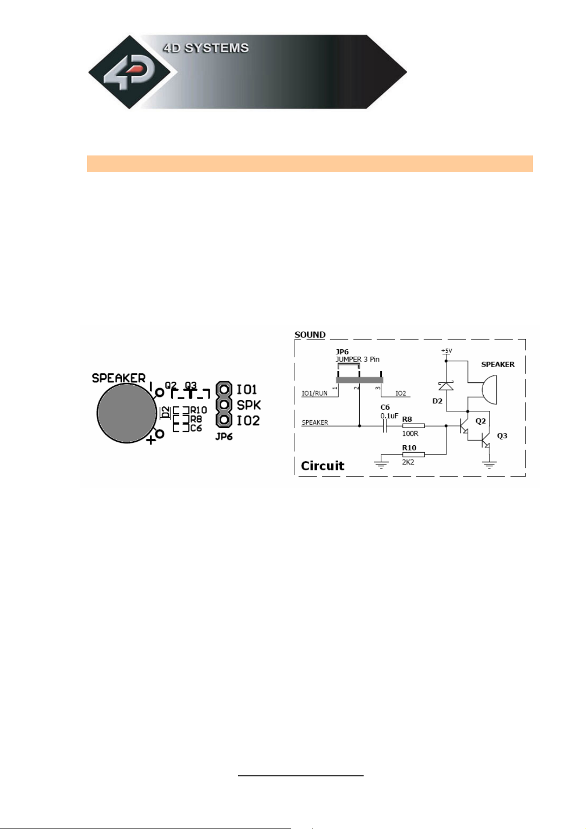
3.5 Speaker – for Sound and Music Generation
The µOLED-96/128/160-G1 display modules, under 4DGL program
applications, are capable of generating complex sounds and music from
their respective I/O pins. Using a shunt and shorting any of the 2 pins of
the 3-pin jumper (JP6) will redirect the output of either IO1 or the IO2
pins from the display module to the speaker circuit. The µOLED-96-G1
module has only a single I/O pin (IO1), therefore only the IO1-SPK pins
can be shorted and are usable. The µOLED-128-G1 and the µOLED-
160-G1 modules have 2 I/O pins (IO1 and IO2) that can be used to
generate sound so either IO1-SPK or IO2-SPK pair of pins can be shorted
and used.
Page 11

DEVBOARD- G1
www.4dsystems.com.au
Development and Educational Tools
11
3.6 Joystick – 5 Position Multi Switch
The Joystick is a 5 position multi switch and each position connects to a
junction of a resistor ladder network that forms a voltage divider. The IO1
pin of µOLED-96/128/160-G1 display modules can be programmed as
an Analogue to Digital (A2D) converter input under 4DGL. Utilising the
A2D feature each individual switch position voltage value can be read and
decoded. Using a shunt and shorting the 2-pin jumper (JP5) will directly
connect the output of the joystick voltage divider circuit to the IO1 pin of
the display modules.
Page 12
DEVBOARD- G1
www.4dsystems.com.au
Development and Educational Tools
12
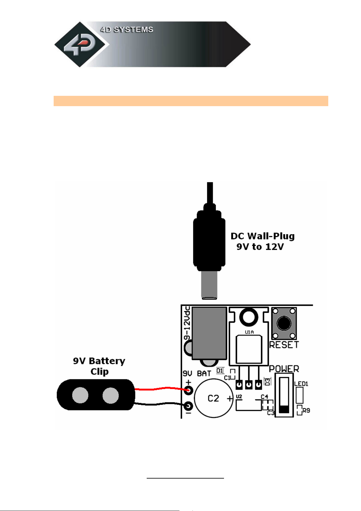
3.7 Power Supply
The DEVBOARD-G1 can be powered by the 5 Volts supply provided by the
µUSB-MB5 or the µUSB-CE5 modules or it can be powered by an external
wall-plug (9 Volts to 12 Volts DC) centre tap positive. The board also has
provisions for soldering a flying lead 9V battery clip. Both the wall plug
and the 9V battery clip are not provided.
Page 13

DEVBOARD- G1
www.4dsystems.com.au
Development and Educational Tools
13
3.8 Solderless Breadboard – Circuit Prototyping
The DEVBOARD-G1 is supplied with a 170 tier (2 sets of 5 rows x 17
column sockets) solder-less breadboard for circuit prototyping purposes.
Each column of 5 sockets has metal strips inside it that connect the
sockets together which simplifies hooking up components. It is also
supplied with 40 pieces of jumper wires of various lengths that can be
used join signals to external components placed on the breadboard.
Page 14
DEVBOARD- G1
www.4dsystems.com.au
Development and Educational Tools
14
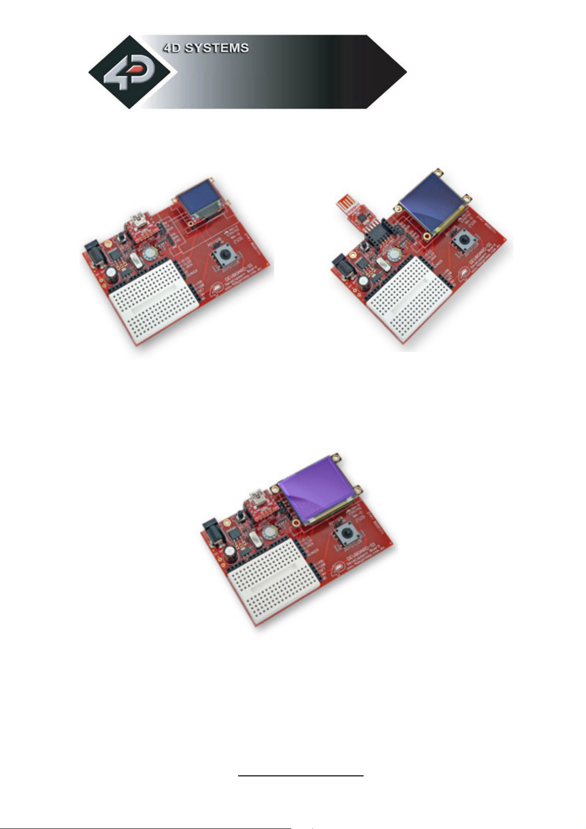
with µOLED-96-G1 and µUSB-MB5 with µOLED-128-G1 and µUSB-CE5
with µOLED-160-G1 and µUSB-MB5
Page 15

DEVBOARD- G1
www.4dsystems.com.au
Development and Educational Tools
15
4 Related Products and Software Tools
µUSB-MB5
www.4dsystems.com.au/prod.php?id=18
µUSB-CE5
www.4dsystems.com.au/prod.php?id=19
µOLED-96-G1
www.4dsystems.com.au/prod.php?id=9
µOLED-128-G1
www.4dsystems.com.au/prod.php?id=28
µOLED-160-G1
www.4dsystems.com.au/prod.php?id=29
4DGL Workshop (free compiler and editor software tool)
www.4dsystems.com.au/developers/index.php
4D Graphics Composer (free software tool)
www.4dsystems.com.au/downloads/Graphics_Composer/
Support Forum
www.websitetoolbox.com/tool/mb/4d
 Loading...