

Page 1

Armadillo-43(T)
4.3” Linux based Display Module
Armadillo-43 (Non-Touch)
Armadillo-43T (Resistive Touch)
Document Date: 16th February 2015
Document Revision: 1.0
DATASHEET
Please refer to the 4D Systems website for the latest Revision of this document
Uncontrolled Copy when printed or downloaded.
Page 2

Armadillo-43(T) – Linux based Computer Display Module
Contents
1. Description ............................................................................................................................. 4
2. Features ................................................................................................................................. 4
3. Pin Configuration and Summary .............................................................................................. 5
4. Getting Started ....................................................................................................................... 7
4D Systems Image (Recommended) ...................................................................................................... 7 4.1.
Standard Image (Not Recommended) ................................................................................................... 8 4.2.
Powering Up ........................................................................................................................................... 9 4.3.
First Start Up .......................................................................................................................................... 9
4.4.
Updating the System ............................................................................................................................ 10 4.5.
5. Configuring Peripherals ......................................................................................................... 10
GPIO ..................................................................................................................................................... 10 5.1.
SPI ......................................................................................................................................................... 10 5.2.
I2C ........................................................................................................................................................ 10 5.3.
PWM..................................................................................................................................................... 10 5.4.
Special PWM ........................................................................................................................................ 11 5.5.
Serial UART ........................................................................................................................................... 11 5.6.
Audio – On Board and External ............................................................................................................ 11 5.7.
Resistive Touch Screen ......................................................................................................................... 11
5.8.
USB Host ............................................................................................................................................... 12 5.9.
microSD Card Socket .......................................................................................................................... 12 5.10.
TFT LCD Display Backlight ................................................................................................................... 12 5.11.
6. How To… .............................................................................................................................. 13
Armadillo Configuration Tool ............................................................................................................... 13 6.1.
Connect to the Internet ....................................................................................................................... 13 6.2.
Setting the Serial UART for User Control ............................................................................................. 13 6.3.
Control the LCD Backlight..................................................................................................................... 14 6.4.
Calibrating the Touch Screen ............................................................................................................... 14 6.5.
Rotating the Display Orientation.......................................................................................................... 14
6.6.
The User Button ................................................................................................................................... 14 6.7.
Startup - X Windows or Terminal ......................................................................................................... 15 6.8.
Selecting Default X Windows ............................................................................................................... 15 6.9.
Changing the Resolution / Scale ......................................................................................................... 15 6.10.
7. Notes ................................................................................................................................... 17
8. Scribble Box .......................................................................................................................... 17
9. BCM2835 GPIO Pinout Information ....................................................................................... 18
Page 3
Armadillo-43(T) – Linux based Computer Display Module
10. Mechanical Details .............................................................................................................. 19
11. Specifications and Ratings ................................................................................................... 20
12. Legal Notice ........................................................................................................................ 22
13. Contact Information............................................................................................................ 22
Page 4

Armadillo-43(T) – Linux based Computer Display Module
4D SYSTEMS Armadillo-43(T) – Linux based Computer Display Module
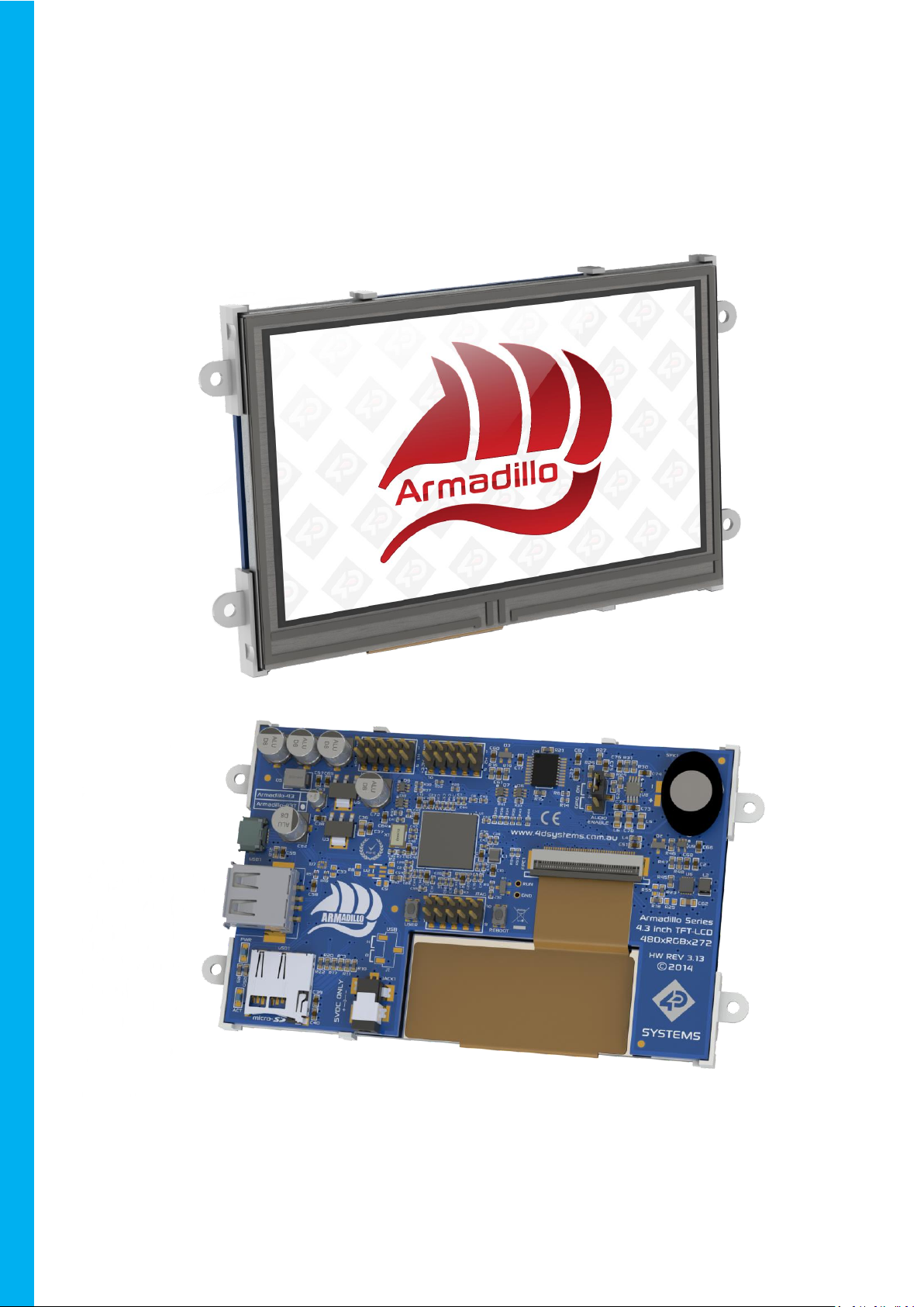
1. Description
The Armadillo is a complete Linux based computer
display module with build in 24bit colour 480x272
resolution TFT LCD display, and features a Resistive
Touch display (Armadillo-43T), or non-touch
display (Armadillo-43) on special request.
At the heart of the Armadillo is a Broadcom
BCM2835 System-On-Chip (SoC), which combines
an ARM1176JZF-S CPU Processor with a VideoCore
IV GPU in a single package. The Armadillo-43
features 512MB of RAM, which is shared between
the CPU and the GPU.
The Armadillo requires a microSD card loaded with
an appropriate image in order to start up, as it
features no on board Flash memory itself, and
uses the microSD card for booting and persistent
storage.
By default, the Armadillo has been developed to
utilise the Raspbian Operating System, which is
based on Debian and optimised for the BCM2835.
Raspbian is the operating system primarily used by
the Raspberry Pi* which has a large following and
development community. The Armadillo, which
uses the same SoC, can utilise a majority of
applications written for the Raspberry Pi.
The Armadillo features 14 GPIO, of which 2 can be
used for a single I2C Channel, 5 can be used for a
single SPI Chanel (with 2 Chip Selects), and 2 can
be used for a single Serial UART. There is also 2
PWM channels which are available for the User,
one of which is shared with the Mono Audio
output via the on board amplifier and mini
speaker.
Each of the GPIOs feature clamping diodes which
protect the GPIO from accidental overvoltage,
typically if connected to 5V devices.
The Armadillo features a single on board USB A
Socket, for connecting to devices such as
Keyboards, USB Storage, USB Hubs, WiFi,
Bluetooth, Ethernet etc.
Note*: Raspberry Pi is a trademark of the
Raspberry Pi Foundation, and all references to the
words ‘Raspberry Pi‘ or the use of its logo/marks
are strictly in reference to the Raspberry Pi
product, and how this product is compatible with
aspects of the product but is not associated with
the Raspberry Pi Foundation in any way.
2. Features
• High Performance 4.3” Linux based computer
display module
• 480x272 Resolution, RGB 16M true to life
colours, TFT Screen with integrated 4-wire
Resistive Touch Panel or a non-touch version is
available on special request, (subject to MOQ).
• Microchip AR1021 Resistive Touch Controller, on
a dedicated I2C Bus.
• Display output is the primary display of the
BCM2835 SoC.
• Capable of being powered off a PC USB Port
(typically current draw is ~400mA), 5VDC Barrel
Jack for use with a 4D Systems Power Adaptor,
or via the GPIO connector 5V pin.
• PWM controlled backlight brightness clocked by
PCM Clock with DMA, freeing up the Hardware
PWM.
• PWM mono audio output, available as Line Out
on H2 Header, or out of on board amplifier and
speaker. On-board amplifier can be disabled via
a GPIO.
• User Button connected to one of the GPIO,
enabling convenient on board button for
triggering specific User actions. Reset Button
which performs a hard reset of the system.
• 2x 10 way headers for Power, GPIO and Audio,
featuring 14 GPIO which can be configured for
SPI, I2C, PWM and Serial UART, along with a
mono Line Out Audio pin.
• 1x JTAG 10 way header
• Capable of full motion multimedia playback.
• Compatible with Raspbian Linux
• Module dimensions: 120.7 x 69.6 x 16.5mm
(including corner plates). Weighing ~ 100g.
• Display Viewing Area: 95.0 x 53.9mm
• 4x corner plates with 2.6mm holes for
mechanical mounting.
• Compatible with the 4DBEZEL-43 display bezel
surround.
• RoHS and CE Compliant.
© 2015 4D SYSTEMS Page 4 of 22 www.4dsystems.com.au
Page 5
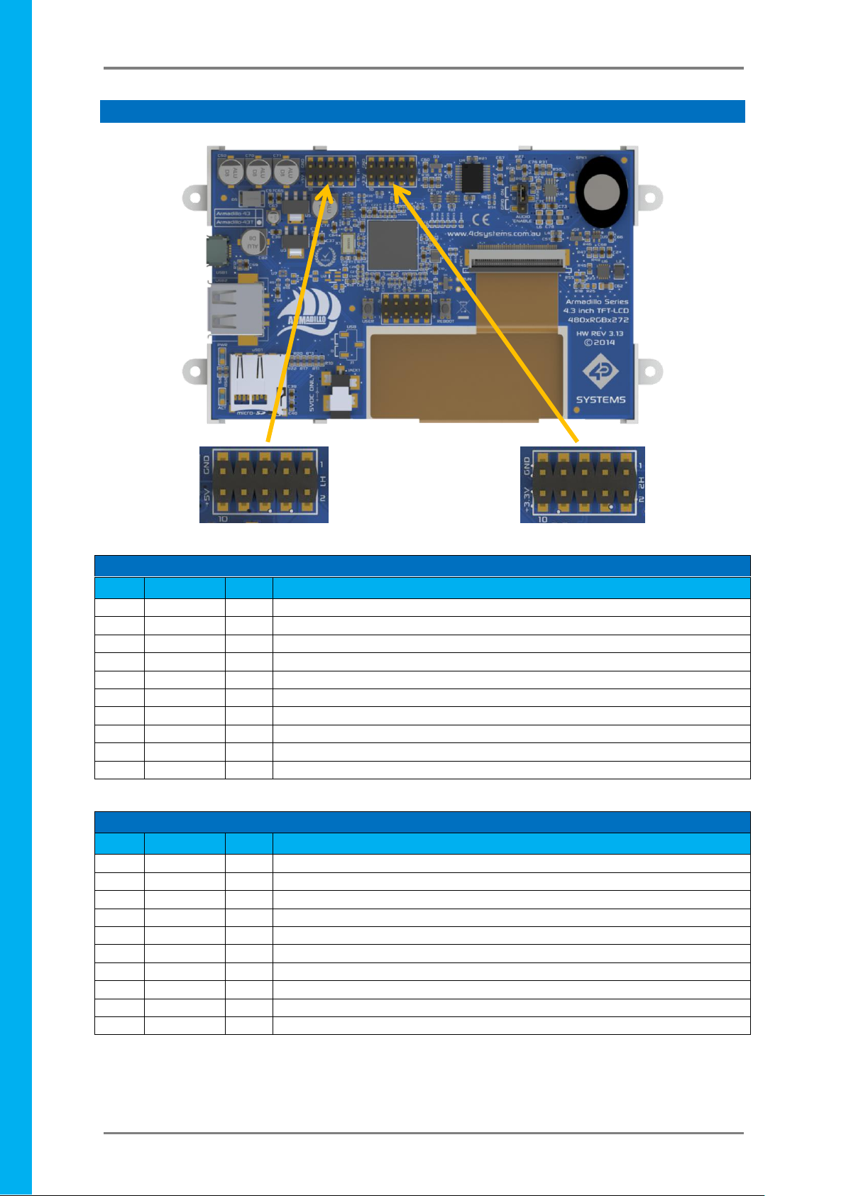
Armadillo-43(T) – Linux based Computer Display Module
H1 Pinout
Pin
Symbol
I/O
Description
1
GPIO37
I/O
3.3V GPIO, 5V Tolerant - can be configured as SPI0 MISO Pin
2
GPIO38
I/O
3.3V GPIO, 5V Tolerant - can be configured as SPI0 MOSI Pin
3
GPIO39
I/O
3.3V GPIO, 5V Tolerant - can be configured as SPI0 SCLK Pin
4
GPIO35
I/O
3.3V GPIO, 5V Tolerant - can be configured as SPI0 CS1 Pin
5
GPIO36
I/O
3.3V GPIO, 5V Tolerant - can be configured as SPI0 CS0 Pin
6
GPIO45
I/O
3.3V GPIO, 5V Tolerant - can be configured as I2C1 SCL Channel
7
GPIO31
I/O
3.3V GPIO, 5V Tolerant
8
GPIO44
I/O
3.3V GPIO, 5V Tolerant - can be configured as I2C1 SDA Channel
9
GND
P
Ground Pin, System Ground
10
+5V
P
5V Supply Pin, can be used to power the Armadillo or source 5V from it.
H2 Pinout
Pin
Symbol
I/O
Description
1
LOUT
O
Line Out level Mono Audio Signal, Filtered PWM Signal
2
GND
P
Ground Pin, System Ground
3
GPIO41
I/O
3.3V GPIO, 5V Tolerant - can be configured as a PWM (Shared with LOUT)
4
GPIO40
I/O
3.3V GPIO, 5V Tolerant - can be configured as a PWM
5
GPIO34
I/O
3.3V GPIO, 5V Tolerant - can be used to disable the on board Audio Amplifier
6
GPIO46
I/O
3.3V GPIO, 5V Tolerant - also connected to the USER button
7
GPIO33
I/O
3.3V GPIO, 5V Tolerant - can be configured as RX0 Serial UART
8
GPIO32
I/O
3.3V GPIO, 5V Tolerant - can be configured as TX0 Serial UART
9
GND
P
Ground Pin, System Ground
10
+3.3V
P
3.3V Supply Pin, used to source 3.3V from to power external devices
H1 Pin 1
H1 Pin 2
H1 Pin 10
H1 Pin 9
H2 Pin 1
H2 Pin 2
H2 Pin 10
H2 Pin 9
4D SYSTEMS Armadillo-43(T) – Linux based Computer Display Module
3. Pin Configuration and Summary
I = Input, O = Output, P = Power
© 2015 4D SYSTEMS Page 5 of 22 www.4dsystems.com.au
Page 6
Armadillo-43(T) – Linux based Computer Display Module
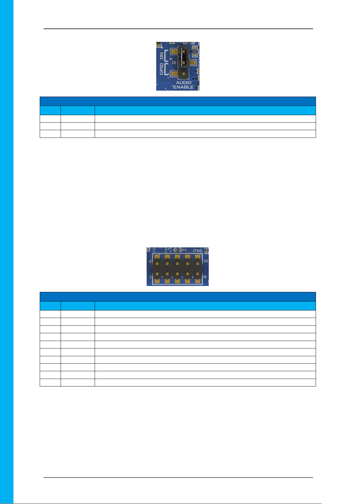
J2 Jumper Header
Pin
Symbol
Description
1
+3.3V
Pull Up to 3.3V
2
SHDN
Shutdown pin of the on board Audio Amplifier
3
GPIO34
GPIO34 Connection, to allow GPIO control of the on board Amplifier Audio Enable
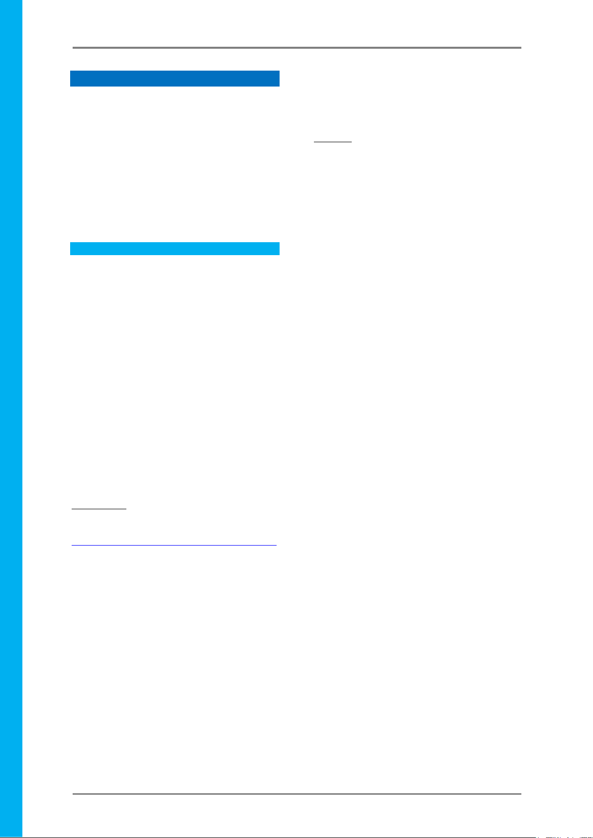
JTAG Header
Pin
Symbol
Description
1
GND
Ground Pin, System Ground
2
TCK
Test Clock Signal
3
GND
Ground Pin, System Ground
4
TMD / TMS
Test Mode Select Signal
5
GND
Ground Pin, System Ground
6
TDO
Test Data Out Signal
7
GND
Ground Pin, System Ground
8
TDI
Test Data In Signal
9
GND
Ground Pin, System Ground
10
TRST_N
Test Reset Signal
4D SYSTEMS Armadillo-43(T) – Linux based Computer Display Module
Connecting J2 between pins 1 and 2 will allow the on board Audio Amplifier to be enabled and any audio that
is generated on the PGIO41 PWM signal (PWM1) will be amplified and played on the on-board speaker.
Connecting J2 between pins 2 and 3 will allow the GPIO34 pin to control the on Board Audio Amplifier’s
shutdown pin. This will allow a User to write a script or piece of software to enable or disable the on board
audio amplifier as required. This can be useful for many reasons, such as power saving, muting the audio, or for
using the PWM signal for another reason – such as motor control. If the on board Audio Amplifier is disabled
the PWM signal can be utilised by the User for other applications, other than Audio.
Removing the jumper entirely (or placing it over 1 pin only for safe storage) will force the on board Amplifier to
disable. This can be useful for many reasons, as per connecting between pins 2 and 3, however with the added
benefit that GPIO34 is also freed up to be used as a GPIO for other purposes. This can be helpful if you wish to
use the PWM1 signal for something other than Audio, and also require the GPIO34 signal for something other
than Audio Enable.
The JTAG header is used in the factory to program the bootloader into the BCM2835 SoC. It can also be used to
connect to a compatible JTAG debugger, however should only be utilised by Advanced users who know what
they are doing. This header makes for good mechanical support when adding a Daughter Board onto the
Armadillo-43T, if nothing else.
Currently there is no information available that can be provided in order to utilise this JTAG header, such as
which JTAG debugger can be utilised by a User or what software is required.
NOTE: Do not electrically connect anything to this header unless you know what you are doing.
© 2015 4D SYSTEMS Page 6 of 22 www.4dsystems.com.au
Page 7
Armadillo-43(T) – Linux based Computer Display Module
4D SYSTEMS Armadillo-43(T) – Linux based Computer Display Module
4. Getting Started
The Armadillo is designed to use the Raspbian
Operating System. There is the choice to use an
image from 4D Systems, which is built from source
and specifically customized to suit the Armadillo
and touch screen operation (Armadillo-43T only),
or a standard Raspbian image, such as one from
the Raspberry Pi website. Using a standard
Raspbian image will require modifications of that
image in order to make it compatible for use with
the Armadillo.
4D Systems Image (Recommended) 4.1.
4D Systems has built and customised a Raspbian
Image from source to cater for the needs of the
Armadillo. It includes changes such as a custom
VC4 firmware (start.elf), customised Kernel to
allow for a driver in the kernel for the Touch
Screen, and then minor modifications to optimise
the display content to fit on the 480x272 display,
along with custom applications such as Armadilloconfig, which is used to configure various aspects
of the system using the touch screen.
The latest image is available for download from
the Armadillo product page on the 4D Systems
website.
Once downloaded and extracted the zip archive,
the image inside should be loaded onto a 4GB or
higher capacity microSD card.
For Windows
Using the Win32DiskImager tool, available for
download from:
http://sourceforge.net/projects/win32diskimager/
1) Insert the microSD card into your card reader
and check which drive letter was assigned.
2) Download the Win32DiskImager utility from
the Sourceforge Project page mentioned
above.
3) Extract the executable from the zip file and
run the Win32DiskImager utility; you may
need to run the utility as administrator. Rightclick on the file, and select Run as Admin.
4) Select the image file you extracted above.
5) Select the drive letter of the microSD card in
the device box. Be careful to select the correct
drive; if you get the wrong one you can
destroy your data on the computer's hard
disk! If you are using a microSD or SD card slot
with an Adaptor in your computer and can't
see the drive in the Win32DiskImager window,
try using a cheap microSD adaptor in a USB
port.
6) Click Write and wait for the write to complete.
7) Exit the imager and eject the SD card.
For Linux
(Credit - Instructions from Raspberry Pi website)
1) Run df -h to see what devices are currently
mounted.
2) If your computer has a slot for SD cards, insert
the card. If not, insert the card into an SD card
reader, then connect the reader to your
computer.
3) Run df -h again. The new device that has
appeared is your SD card. The left column
gives the device name of your SD card; it will
be listed as something like:
/dev/mmcblk0p1 or /dev/sdd1
The last part (p1 or 1 respectively) is the
partition number but you want to write to the
whole SD card, not just one partition.
Therefore you need to remove that part from
the name for example,
/dev/mmcblk0 or /dev/sdd as the device for
the whole SD card. Note that the SD card can
show up more than once in the output of df; it
will do this if you have previously written an
image to this SD card, because images
typically have more than one partition.
4) Now that you've noted what the device name
is, you need to unmount it so that files can't
be read or written to the SD card while you
are copying over the SD image.
5) Run umount /dev/sdd1, replacing sdd1 with
whatever your SD card's device name is
(including the partition number).
6) If your SD card shows up more than once in
the output of df due to having multiple
partitions on the SD card, you should
unmount all of these partitions.
7) In the terminal, write the image to the card
with the command below, making sure you
replace the input file if= argument with the
path to your .img file, and the /dev/sdd in the
output file of= argument with the right device
name. This is very important, as you will lose
all data on the hard drive if you provide the
wrong device name. Make sure the device
name is the name of the whole SD card as
described above, not just a partition of it; for
example sdd, not sdds1 or sddp1;
or mmcblk0, not mmcblk0p1.
dd bs=4M if=path_of_your_image.img
of=/dev/sdd
© 2015 4D SYSTEMS Page 7 of 22 www.4dsystems.com.au
Page 8

Armadillo-43(T) – Linux based Computer Display Module
4D SYSTEMS Armadillo-43(T) – Linux based Computer Display Module
8) Please note that block size set to 4M will work
most of the time; if not, please try 1M,
although this will take considerably longer.
9) Also note that if you are not logged in as root
you will need to prefix this with sudo.
10) The dd command does not give any
information of its progress and so may appear
to have frozen; it could take more than five
minutes to finish writing to the card. If your
card reader has an LED it may blink during the
write process. To see the progress of the copy
operation you can run pkill -USR1 -n -x dd in
another terminal, prefixed with sudo if you
are not logged in as root. The progress will be
displayed in the original window and not the
window with the pkill command; it may not
display immediately, due to buffering.
11) Instead of dd you can use dcfldd. It will give a
progress report about how much has been
written.
12) You can check what's written to the SD card
by using dd from the card back to another
image on your hard disk, and then
running diff (or md5sum) on those two
images. There should be no difference.
13) Remove the SD Card from your PC, it is now
ready to use.
For Mac OS
(Credit - Instructions from Raspberry Pi website)
1) Connect the SD card reader with the SD card
inside. Note that it must be formatted in
FAT32.
2) From the Apple menu, choose About This
Mac, then click on More info...; if you are
using Mac OS X 10.8.x Mountain Lion then
click on System Report.
3) Click on USB (or Card Reader if using a built-in
SD card reader) then search for your SD card
in the upper right section of the window. Click
on it, then search for the BSD name in the
lower right section; it will look something like
'diskn' where n is a number (for example,
disk4). Make sure you take a note of this
number.
4) Unmount the partition so that you will be
allowed to overwrite the disk; to do this, open
Disk Utility and unmount it (do not eject it, or
you will have to reconnect it). Note that On
Mac OS X 10.8.x Mountain Lion, "Verify Disk"
(before unmounting) will display the BSD
name as "/dev/disk1s1" or similar, allowing
you to skip the previous two steps.
5) From the terminal run:
sudo dd bs=1m if=your_image.img
of=/dev/diskn
6) Remember to replace n with the number that
you noted before!
You should now have a SD card ready to use in the
Armadillo.
Standard Image (Not Recommended) 4.2.
A standard image of Raspbian for the Raspberry Pi
can be used for the Armadillo, with some
modifications made to it so it operates the on
board display.
Note, this is not specifically supported by 4D
Systems as 4D Systems has no influence over
images produced for the Raspberry Pi, and
therefore cannot guarantee compatibility.
Using a standard image will mean you miss out on
a number of benefits that come with the 4D
Systems image, however the module should still
be fully functional.
Simply download a Raspbian Image from the
Raspberry Pi website (Note: NOOBS is not
supported)
http://www.raspberrypi.org/downloads/
Follow the same 7 instructions as found in the
previous section, and image a microSD card, but
this time using the Raspberry Pi image.
Once you have an image on the card, you need to
replace some of the files so the hardware is able to
be used. Don’t attempt to boot the card in the
Armadillo-43T yet, it will not work.
Download the ‘Boot Files Pack’ and ‘Kernel Pack’
from the Armadillo product page on the 4D
Systems website.
To convert a standard Raspbian image for the
Raspberry Pi so it will function on the Armadillo43T you first have to replace the main boot file.
This file is usually called "start.elf" and is in the FAT
(DOS) partition of the image. It is possible this file
may be called something else (some images use
"start_x.elf"). Replace the file with the "start.elf"
file from the ‘Boot File Pack’ archive, renaming it if
necessary.
This will only allow the system to boot and operate
the display. It will not allow the use of the touch
screen. For this a different set of kernel drivers are
needed. You will need to manually replace your
current kernel with the version from the ‘Kernel
Pack’ archive. Therefore you are likely to require a
USB Keyboard.
© 2015 4D SYSTEMS Page 8 of 22 www.4dsystems.com.au
Page 9

Armadillo-43(T) – Linux based Computer Display Module
4D SYSTEMS Armadillo-43(T) – Linux based Computer Display Module
The kernel archive contains all the kernel modules
which need to be extracted from within a running
system since they need to go in the main
filesystem of the image (the ext4 partition).
The kernel archive also contains the kernel image
(boot/kernel.img) which is to be placed in the
same partition as the start.elf above, renaming it
to the same as the existing image. This should be
done last by manually copying the file as above
with the SD card connected direct to your
computer.
Once all the files have been installed the system
should be able to support the touch screen. The
drivers still need to be activated before they will
operate, however.
These two commands should be added to
/etc/rc.local:
chmod 777 /sys/class/i2c-adapter/i2c0/new_device
echo ar1020_i2c 0x4d > /sys/class/i2cadapter/i2c-0/new_device
At this point the Armadillo can be rebooted, and
the touch screen should be functional.
Note: by using a Raspberry Pi Raspbian image, you
miss out on a number of benefits of the 4D
Systems Raspbian image. Armadillo-config is not
available, for example.
Powering Up 4.3.
The Armadillo can be powered up in 3 different
ways. It features a DC Barrel Jack, a microUSB
socket, and power pins on the H1 header (2.54mm
/ 0.1” pitch header). Any of these can be used to
power the Armadillo-43T.
The DC Barrel Jack is designed for a fine pitch DC
Jack, 2.35mm in diameter, with a centre hole of
0.7mm, and barrel length of 8mm or more.
A suitable 1 Amp 5.0V DC Adaptor is available from
the 4D Systems website. This DC Adaptor comes
with interchangeable heads so it can be used
around the world in a range of AC sockets and
voltages.
The Barrel Jack on board the Armadillo is a CUI Inc
PJ1-023-SMT, if more information is required.
The microUSB socket accepts a standard microUSB
cable, which can be connected to a PC or to an
AC/DC adaptor, such is commonly used on Cell
Phones, Digital Cameras and is also used for the
Raspberry Pi. At least 500mA is required, however
a 1A supply is recommended. Some PC’s may not
be able to supply the required current for the
Armadillo to boot up or to be stable, when
powered from USB.
The Power pins on the H1 Header are +5V and
GND, and can be connected to any smooth
regulated 5VDC Power source. The +3.3V and GND
pins can NOT be used to power the Armadillo as it
requires 5V for the system to operate. Connecting
Power to the +3.3V and GND Pins will result in
unpredictable results, and will not result in correct
operation with the TFT LCD. The +3.3V pin is an
Output, to power external devices only.
Applying power to any of these power points on
the Armadillo will power the Armadillo up, and it
will initiate the boot sequence from the microSD
card.
First Start Up 4.4.
Once power is applied, the Armadillo boot logo
should appear on the TFT LCD Display to show the
GPU has booted (Assuming the use of the 4D
Raspbian Image). Following that should be the
console prompts showing the Firmware, Kernel
and OS boot messages. When using the 4D
Systems image, a few startup questions will be
asked, which the answers can be entered from the
touchscreen display. Questions include the setup
of a Username/Password, Resizing of the microSD
partitions (if required), and selecting if you want it
to boot into the X GUI at startup. If you have a
WiFi dongle connected at first startup, it will
prompt you for SSID/Password so you can use Wifi
as soon as you load the X GUI.
It can be useful to have a USB Keyboard connected
to the Armadillo, until it is set up the way you
want it, as the touch screen by default can only
replace the left click of a mouse. With the use of
the Armadillo-config utility however, many aspects
of the system can be setup using the touch screen
alone, such as connecting to a WiFi network using
a USB WiFi dongle, inputting your SSID and
Password with the touch screen, selecting the
orientation of the display, along with many other
configurable features.
© 2015 4D SYSTEMS Page 9 of 22 www.4dsystems.com.au
Page 10

Armadillo-43(T) – Linux based Computer Display Module
Header
GPIO Number
Signal Name
H1 Pin 1
GPIO37
SPI0 MISO
H1 Pin 2
GPIO38
SPI0 MOSI
H1 Pin 3
GPIO39
SPI0 SCK
H1 Pin 4
GPIO35
SPI0 CS1
H1 Pin 5
GPIO36
SPI0 CS0
Header
GPIO Number
Signal Name
H1 Pin 6
GPIO45
I2C1 SCL
H1 Pin 8
GPIO44
I2C1 SDA
Header
GPIO Number
Signal Name
H2 Pin 3
GPIO41
PWM1
H2 Pin 4
GPIO40
PWM0
4D SYSTEMS Armadillo-43(T) – Linux based Computer Display Module
Updating the System 4.5.
The Armadillo (when used with the 4D Systems
Image) is easily kept up to date using the standard
update calls from Terminal.
sudo apt-get update
sudo apt-get upgrade
These will update the modules use in the image,
without breaking the functionality of the
Armadillo.
If a standard Raspbian image is used, then doing
an update/upgrade could result in the Armadillo
not booting, due to the chance that things like the
VC4 Firmware (start.elf) being updated/
overwritten with a standard one. If this happens,
the ‘Raspbian Mod Package’ download should be
downloaded from the Product Page and the files
on your SD card should be overwritten.
5. Configuring Peripherals
The Armadillo-43T has a range of GPIO available to
the User, for use in a range of applications, such as
communicating to other devices over Serial, SPI or
I2C, or to trigger or receive digital signals via the
Digital inputs/outputs.
MOSI, MISO and CLK, and also includes 2 Chip
Select signals CS0 and CS1.
The signals can be found on the following pins:
I2C 5.3.
There are 2 of the GPIO which can be configured
to be I2C.
The signals can be found on the following pins:
In addition to this, there is another I2C channel
which is dedicated to the Resistive Touch
Controller, the Microchip AR1021. This second I2C
channel is not available for the User on any of the
Headers as it is dedicated to the Resistive Touch
controller. This utilises the I2C0 channel.
GPIO
5.1.
There are 14 GPIO available for the User, which
can be used as standard digital GPIO, or they can
be configured for alternate functions such as SPI,
I2C, PWM and Serial.
All the GPIO have clamping diodes and resistors on
them, which enable them to be connected to 5V
level signals. All GPIO are however 3.3V TTL level
signals, which means when set to output a logic
level 1 or HIGH signal, the voltage at the pin is
~3.3V. Due to the clamping diodes, these GPIO can
accept 5V TTL level signals when configured as
inputs, to provide the User with a greater flexibility
for end applications.
Note: Any devices that are interfaced to the
Armadillo need to be compatible with 3.3V logic.
SPI 5.2.
There are 5 of the GPIO which can be configured
to be SPI. This includes the 3 main SPI signals,
PWM 5.4.
There are two GPIO which can be used for PWM or
GPIO, and one of the PWMs (when enabled) is
earmarked for generating Audio either to the
LOUT (Line Out) pin, and to the on board amplifier
and speaker.
In order to use PWM1 for anything other than
Audio, then the on board amplifier needs to be
disabled. Please refer to the J2 Jumper Header
information, found in Section 3.
The signals can be found on the following pins:
By default, PWM1 is set to PWM for the Audio,
and PWM0 is set to be a GPIO.
Note: Due to the nature of the Raspbian operating
system, any pin that is configured to be PWM can
© 2015 4D SYSTEMS Page 10 of 22 www.4dsystems.com.au
Page 11

Armadillo-43(T) – Linux based Computer Display Module
Header
GPIO Number
Signal Name
H2 Pin 7
GPIO33
RX0
H2 Pin 8
GPIO32
TX0
4D SYSTEMS Armadillo-43(T) – Linux based Computer Display Module
be ‘taken over’ by the audio system, if audio is
started, such as playing a movie.
Please refer to section 5.7 “Audio – On Board and
External” for more information on using the PWM
for audio.
Special PWM 5.5.
4D Systems has developed a driver for the
Armadillo which has the ability to clock most of
the GPIO with a PWM clock generated by the
unused PCM clock on the BCM2835, coupled with
DMA.
One of these pins is allocated to the Backlight, to
allow the backlight to be dimmed. Please refer to
the “TFT LCD Display Backlight” section for more
information.
In regards to the additional PWMs, an Application
Note will be made available to detail how to use
these, and what the limitations are. This will be
available on the 4D Systems website, Application
Note page.
Serial UART 5.6.
There are two GPIO which by default are
configured to be a Serial UART. These can be used
as GPIO instead if required.
The signals can be found on the following pins:
This Serial UART can be used to log into the
Armadillo using a serial console application, an
example is Putty. By default the Baud Rate to do
this is 115200. This Serial UART can also be used
for many applications by the User. Some require
control to be removed from Linux so the Serial
UART can be used by the User or the Users
scripts/applications.
Please refer to the “How To” section, and the area
titled “Setting the Serial UART for User Control”.
The Serial port will no longer be used by Linux and
therefore you will no longer be able to log into the
Armadillo using the Serial UART, however this does
now allow your scripts/applications to use the
Serial UART instead.
Audio – On Board and External 5.7.
The Armadillo features an on board amplifier and
tiny speaker, which are connected to the line out
pin which is present on the H2 header.
The on board speaker is small and designed only to
provide a small level of audio capability to the
display module. If the audio level is raised too high
in software, it can cause the output to distort and
become inaudible. The on-board audio capability
of the Armadillo is mono only, and features only a
single (mono) line out signal.
If a more capable audio system is desired to be
connected to the line out signal, the on board
amplifier and speaker can be disabled, and an
external amplifier can be connected to the H2
Header, which would enable a more powerful
audio system to be connected.
If Stereo or better audio is required, both PWM
signals are available on the H2 header, and with
appropriate external filtering circuitry, a more
capable stereo audio system could be created
using these 2 signals. Alternatively, a USB
Soundcard can be connected to the Armadillo.
To disable, enable or control the on-board
amplifier with a GPIO, there is a 3 pin male jumper
header titled JP2, to the left of the speaker, above
the Display flex connector. Please refer to Section
3, “Pin Configuration and Summary” and the table
pertaining to “JP2 Jumper Header” for more
information on this Jumper and its settings.
Resistive Touch Screen 5.8.
The resistive touch screen on the Armadillo-43T is
a 4-wire variety, and interfaces to the BCM2835
SoC via a Microchip AR1021 resistive touch
controller, using the I2C0 bus.
A driver has been provided by Microchip for this
device, which has been integrated into the Kernel
shipped with the 4D Systems Raspbian Image,
which enables the resistive touch controller to be
used.
Inside the modified Kernel which is provided in the
4D Systems Raspbian Image, is a modified I2C
driver which directs the I2C channels to the
appropriate pins, for use by the AR1021 driver.
Calibration of the Resistive Touch is described in
the How To section.
© 2015 4D SYSTEMS Page 11 of 22 www.4dsystems.com.au
Page 12

Armadillo-43(T) – Linux based Computer Display Module
Signal Name
GPIO Number
Description
SD0_CLK
GPIO48
SD Clock
SD0_CMD
GPIO49
SD Command
SD0_DAT0
GPIO50
SD Data bit 0
SD0_DAT1
GPIO51
SD Data bit 1
SD0_DAT2
GPIO52
SD Data bit 2
SD0_DAT3
GPIO53
SD Data bit 3
4D SYSTEMS Armadillo-43(T) – Linux based Computer Display Module
USB Host 5.9.
The Armadillo features a single USB port which is a
USB Host.
The USB Host is capable of connecting to a wide
range of USB peripherals, such as a USB
Keyboard/Mouse, USB Hub, USB Hard Drive, USB
Flash Drive, USB Ethernet Dongle, USB WiFi Dongle
etc.
Using a USB Hub will enable additional USB
Devices to be connected together.
Since the Armadillo-43T utilises the same
processor as the Raspberry Pi, the following
website can be used to assist identifying possible
compatible and incompatible devices.
http://elinux.org/RPi_VerifiedPeripherals
microSD Card Socket 5.10.
The microSD card socket on the Armadillo is used
to hold the image of the Operating System which
is to boot on the Armadillo. It is required and there
are no options to use the Armadillo without having
a microSD card installed.
4D Systems offers suitable microSD cards for use
with the Armadillo, and are ‘Industrial Grade’ Class
10 cards which have advanced firmware for
preventing Read Disturb which is common in
systems that do a lot of reading of data without
necessarily writing over that data. It also offers
wear levelling technology, which is useful in a
system like the Armadillo due to the microSD is
essentially acting as a Hard Drive.
If alternate cards are required you can refer to the
following website which provides information on
tested SD cards (not specifically microSD cards
however) which work on the Raspberry Pi, and
therefore will be the same on the Armadillo-43T.
http://elinux.org/RPi_SD_cards
The microSD card socket itself is connected to the
Armadillo on Bank2 of the BCM2835’s GPIO banks,
and is connected to the SD0 interface.
TFT LCD Display Backlight 5.11.
The Armadillo features a DC/DC Boost converter
for driving the backlight, due to the backlight
requiring a much higher voltage than the
Armadillo’s input voltage.
It utilises the TI TPS61080 0.5A DC/DC Boost
Converter, which is configured in a way which
allows for a PWM input, to enable the backlight to
be dimmed if required.
Due to the BCM2835 SoC only having 2 hardware
PWM channels, the backlight driver does not
utilise any of these hardware PWM signals, as it
was opted to keep these available for the User for
Audio or alternative applications. Instead it uses a
standard GPIO which has a driver written to map it
to the PCM clock, which allows a hardware-like
PWM output to be generated. Please refer to
‘Special PWM’ section for more information. This
ensures that the backlight PWM is stable,
compared to if the PWM was software driven, as if
system load increases the backlight intensity may
change, which would be undesirable.
The backlight control signal is linked to GPIO43,
and can be set as a simple digital GPIO and only
used for On/Off control of the backlight, or it can
be used in PWM mode, and a range of 0-100%
duty cycle on the PWM will set the backlight
brightness. By default, the Armadillo controls the
backlight with a 130Hz PWM.
A Backlight driver has been written to simplify the
interface for controlling the backlight.
Please refer to the “How To” section, and the area
titled “Control the LCD backlight”, for more
information.
© 2015 4D SYSTEMS Page 12 of 22 www.4dsystems.com.au
Page 13

Armadillo-43(T) – Linux based Computer Display Module
4D SYSTEMS Armadillo-43(T) – Linux based Computer Display Module
6. How To…
Here are a few examples of how to use the
Armadillo.
Note: Most instructions in this section are relevant
only for the 4D Systems Raspbian image, as
Armadillo-config is not supported on 3rd part
Raspbian distributions.
Armadillo Configuration Tool 6.1.
Built into the 4D Systems Image for the Armadillo,
is a custom 4D Systems tool called ArmadilloConfig.
This tool does a lot of the hard work in regards to
the configuration of some core settings, and
enables these settings to be configured from the
touch screen display, so an external
keyboard/mouse is not required.
To run Armadillo-config from the X GUI, simply
select it from the Start Menu.
To run Armadillo-config from Terminal, it needs to
be run as root, simply type:
sudo armadillo-config
Configuration of WiFi, Ethernet, Touchscreen
Calibration, Option to Boot to X Windows or to
Terminal, Configuring what the User Button does,
Adjusting the scaling (resolution) of the display,
Rotating the display, along with many other
features are possible from this neat tool.
Connect to the Internet 6.2.
The Armadillo does not feature any on board
peripherals to enable Internet Connection itself,
however it does offer a single USB Port which can
be used to connect to external network devices.
This USB Port can be used to connect to
networking peripherals such as USB Ethernet
dongles, USB Wifi dongles and various other
networking hardware.
Armadillo-config can be used to set up the WiFi
network, configured using the Armadillo’s touch
screen. This tool can be launched from the X GUI
or from Terminal, and is self-explanatory in its use.
Simply go to the WiFi or Ethernet sections of the
tool (if you have hardware connected to suit), and
enter the required information using the touch
screen display, or using an external
keyboard/mouse.
You will need to restart the Armadillo for these
changes to take effect.
To run Armadillo-config from the X GUI, simply
select it from the Start Menu.
To run Armadillo-config from Terminal, simply
type:
sudo armadillo-config
Setting the Serial UART for User Control 6.3.
By default the on board Serial UART on the
Armadillo-43T is used by the Linux system as a
debug console, and can be used to log into the
Armadillo-43T or for controlling the system, rather
than having a USB Keyboard connected. In order
to use this Serial UART for other purposes, such as
inside a Python application, the Serial UART needs
to be disconnected from the linux system, so it is
available to the User.
This can be achieved by editing the cmdline.txt file
which is found on the DOS/FAT partition of the
microSD card.
From terminal, launch leafpad (or your chosen
editor) with root:
sudo leafpad /boot/cmdline.txt
Remove the following text (LEAVE everything else
intact):
© 2015 4D SYSTEMS Page 13 of 22 www.4dsystems.com.au
Page 14

Armadillo-43(T) – Linux based Computer Display Module
4D SYSTEMS Armadillo-43(T) – Linux based Computer Display Module
kgdboc=ttyAMA0,115200 console=tty1
Save the file, overwriting the existing one.
Navigate and edit /etc/inittab using the same
method above
sudo leafpad /etc/inittab
Comment out the bottom line by putting a '#'
symbol at the start of it, where the bottom line is:
T0:23:respawn:/sbin/getty -L ttyAMA0
115200 vt100
Save the file, overwriting the existing one.
Reboot the Armadillo.
When rebooted, the Armadillo will have its Serial
UART available for the User.
Rotating the Display Orientation 6.6.
It is possible to rotate the display in order to
satisfy various mounting configurations, such as
Portrait, Landscape, Reverse Portrait and Reverse
Landscape.
This is very simple to do by using the Armadilloconfig tool, which can be found in the ‘start’ menu
of the Raspbian OS, or can be launched via
Terminal by typing:
sudo armadillo-config
Simply click on the Rotate Screen Option, and
select the orientation of your choice.
Control the LCD Backlight 6.4.
In order to control the backlight on the Armadillo,
the backlight driver needs to be enabled, which is
enabled by default on the 4D Systems Raspbian
image.
The backlight can be controlled from the terminal,
or from a bash script. The following command can
be used to set the backlight from 0 to 100%.
echo 80 > /sys/class/backlight/gpiobacklight.0/brightness
The above will set the backlight to 80%. Simply
change the ‘echo 80’ to be anything from 0 to 100.
Calibrating the Touch Screen 6.5.
The touch screen on the Armadillo is controlled
using a Microchip AR1021 Resistive Touch
Controller, which is interfaced to the BCM2835
using I2C. This controller is connected to the I2C0
channel of the BCM2835.
Calibration is easiest launched using the Armadillo
Config tool, which can be found in the ‘start’ menu
of the 4D Systems Raspbian OS, or can be
launched via Terminal by typing:
sudo armadillo-config
Simply click on the icon titled ‘Touch Calibration’
and follow the on screen prompts.
Once this has been selected, click Save, and Exit
the tool. You will need to restart the Armadillo for
the changes to take effect.
The User Button 6.7.
On the back of the Armadillo is a tactile push
button labelled User. This button can be
configured by the User to perform a set action, or
multiple actions, dictated by a bash script which is
executed when the button is pressed.
By default, the button is set to execute a script
called ‘Killthem’, which simply searches for specific
processes running and kills them if they are
running. This is used to kill applications which do
not have touchscreen control and typically require
a keyboard, so the application can be exited
without the need for a keyboard to be connected
to the Armadillo. This script can be edited to suit,
or can be replaced entirely with a different script
for a different purpose, such as safely shutting
down the Armadillo for example.
The User Button is connected to a GPIO on the
BCM2835 SoC, and therefore if the GPIO is to be
used for another purpose, then the User Button
can no longer be used.
© 2015 4D SYSTEMS Page 14 of 22 www.4dsystems.com.au
Page 15

Armadillo-43(T) – Linux based Computer Display Module
4D SYSTEMS Armadillo-43(T) – Linux based Computer Display Module
The User Button is connected to GPIO46.
To edit which script is executed when the User
Button is pressed, simply run the Armadillo Config
tool, which can be found in the ‘start’ menu of the
Raspbian OS, or can be launched via Terminal by
typing:
sudo armadillo-config
Simply click on the User Option, and select the
Script of your choice.
experimental environment which is more suited
for touch screen applications, such as the
Armadillo, however has some issues and is still
under development.
The default X Windows can be selected using the
Armadillo Config tool, which can be found in the
‘start’ menu of the Raspbian OS, or can be
launched via Terminal by typing:
sudo armadillo-config
Simply click on the Desktop icon, and then select
either LXDE or Enlightenment, as required.
Startup - X Windows or Terminal 6.8.
It is possible to enable the Armadillo to boot up
into X Windows, or to the Terminal, using the
Armadillo-config tool, which can be found in the
‘start’ menu of the Raspbian OS, or can be
launched via Terminal by typing:
sudo armadillo-config
Simply click on the Startup button, and select Yes
or No as required. Selecting Yes will boot into X
Windows by default, and Selecting No will boot to
the terminal.
Selecting Default X Windows 6.9.
On the 4D Systems Raspbian Image, are two
different X Windows for the User to select.
One is LXDE, which is the ‘normal’ X Windows
found on the Raspbian Operating System. The
other is called ‘Enlightenment’, which is an
This can be changed again by going back into the
Armadillo Config tool, and selecting the other one,
as required.
Changing the Resolution / Scale 6.10.
A neat feature which is available on the Armadillo,
is the ability for the display output to be scaled to
enable larger windows to display fully, since the
4.3” display can be on the small side when dealing
with some of the default windows found in the X
Windows environment.
Using the Armadillo Config tool, which can be
found in the ‘start’ menu of the Raspbian OS, or
can be launched via Terminal by typing:
sudo armadillo-config
Selecting the ‘Screen Resolution’ icon, will take
you to a page which enables you to change from
the default 480x272 resolution, up to much larger
resolutions. Note however, the actual resolution of
the display is fixed, this cannot be changed, but
the scaling that is output from the frame buffer
can be modified which makes the resolution of the
display appear to change. The limitation of this
however is the larger resolution you select, the
harder things are to read and make out of the
screen, since there are only so many pixels on the
actual display.
© 2015 4D SYSTEMS Page 15 of 22 www.4dsystems.com.au
Page 16

Armadillo-43(T) – Linux based Computer Display Module
4D SYSTEMS Armadillo-43(T) – Linux based Computer Display Module
By default the resolution is 480x272. From testing
at 4D Systems, resolutions up to about 672x380
are perfectly usable, and anything beyond that
requires knowledge of the system and a good eye,
as fine text and icons can be difficult or impossible
to read, especially when dealing with the higher
resolutions.
This functionality is only usable to a certain extent,
but with a little bit of scaling, such as 576x326, it
can make the X Windows environment somewhat
easier to use, due to some windows default to be
larger than the resolution of the Armadillo, making
navigation in some areas tricky without scaling.
© 2015 4D SYSTEMS Page 16 of 22 www.4dsystems.com.au
Page 17

Armadillo-43(T) – Linux based Computer Display Module
4D SYSTEMS Armadillo-43(T) – Linux based Computer Display Module
7. Notes
__________________________________________________________________________________________
__________________________________________________________________________________________
__________________________________________________________________________________________
__________________________________________________________________________________________
__________________________________________________________________________________________
__________________________________________________________________________________________
__________________________________________________________________________________________
__________________________________________________________________________________________
__________________________________________________________________________________________
__________________________________________________________________________________________
__________________________________________________________________________________________
__________________________________________________________________________________________
__________________________________________________________________________________________
__________________________________________________________________________________________
__________________________________________________________________________________________
__________________________________________________________________________________________
__________________________________________________________________________________________
__________________________________________________________________________________________
__________________________________________________________________________________________
__________________________________________________________________________________________
__________________________________________________________________________________________
__________________________________________________________________________________________
__________________________________________________________________________________________
__________________________________________________________________________________________
8. Scribble Box
© 2015 4D SYSTEMS Page 17 of 22 www.4dsystems.com.au
Page 18

Armadillo-43(T) – Linux based Computer Display Module
4D SYSTEMS Armadillo-43(T) – Linux based Computer Display Module
9. BCM2835 GPIO Pinout Information
© 2015 4D SYSTEMS Page 18 of 22 www.4dsystems.com.au
Page 19

Armadillo-43(T) – Linux based Computer Display Module
4D SYSTEMS Armadillo-43(T) – Linux based Computer Display Module
10. Mechanical Details
© 2015 4D SYSTEMS Page 19 of 22 www.4dsystems.com.au
Page 20

Armadillo-43(T) – Linux based Computer Display Module
ABSOLUTE MAXIMUM RATINGS
Operating ambient temperature ................................................................................................... -20°C to +70°C
Storage temperature .......................................................................................................................... -30°C +80°C
NOTE: Stresses above those listed here may cause permanent damage to the device. This is a stress rating only
and functional operation of the device at those or any other conditions above those indicated in the
recommended operation listings of this specification is not implied. Exposure to maximum rating conditions
for extended periods may affect device reliability.
RECOMMENDED OPERATING CONDITIONS
Parameter
Conditions
Min
Typ
Max
Units
Supply Voltage (+5V)
Stable external supply required
4.5
5.0
5.5
V
Operating Temperature
-20
--
+70
°C
GLOBAL CHARACTERISTICS BASED ON OPERATING CONDITIONS
Parameter
Conditions
Min
Typ
Max
Units
Supply Current (ICC)
5V Supply
--
400
--
mA
Display Endurance
Hours of operation, measured to
when display is 50% original
brightness
--
20000
--
H
Touch Screen Endurance
Number of touches/hits with a
12.5mm tip at a rate of 2x per
second with 250gf force
--
1M
--
Touches
Slide stylus on screen, 100gf force,
60mm/s speed with a 0.8mm
polyacetal tip stylus pen
--
100K
--
Slides
Touch Screen Transparency
96
--
--
%
Touch Screen Operational
Force
Only use Finger or Stylus, do not
use anything sharp or metal
20
--
100
gf
LCD DISPLAY INFORMATION
Parameter
Conditions
Specification
Display Type TFT Transmissive LCD
Display Size 4.3” Diagonal
Display Resolution
480 x 272 RGB 24Bit
Display Brightness
5V Supply
480cd/m2
Display Contrast Ratio
Typical
350:1
Display Viewing Angles
Above Centre
35 Degrees
Below Centre
15 Degrees
Left of Centre
45 Degrees
Right of Centre
45 Degrees
Display Viewing Direction
12 o’clock Display
(Optimal viewing is from above)
Display Backlighting
White LED Backlighting
5x2 Parallel LED’s
4D SYSTEMS Armadillo-43(T) – Linux based Computer Display Module
11. Specifications and Ratings
© 2015 4D SYSTEMS Page 20 of 22 www.4dsystems.com.au
Page 21

4D SYSTEMS Armadillo-43(T) – Linux based Computer Display Module
Armadillo-43(T) – Linux based Computer Display Module
Pixel Pitch
0.198 x 0.198mm (Square pixels)
Pixel Density
Number of pixels in 1 row in
25.4mm
128 DPI/PPI
ORDERING INFORMATION
Order Code:
Armadillo-43 (Non Touch Model)
Armadillo-43T (Resistive Touch Model)
Packaging: Module sealed in an antistatic foam padded 4D Systems box
© 2015 4D SYSTEMS Page 21 of 22 www.4dsystems.com.au
Page 22

Armadillo-43(T) – Linux based Computer Display Module
4D SYSTEMS Armadillo-43(T) – Linux based Computer Display Module
12. Legal Notice
Proprietary Information
The information contained in this document is the property of 4D Systems Pty. Ltd. and may be the subject of
patents pending or granted, and must not be copied or disclosed without prior written permission.
4D Systems endeavours to ensure that the information in this document is correct and fairly stated but does
not accept liability for any error or omission. The development of 4D Systems products and services is
continuous and published information may not be up to date. It is important to check the current position with
4D Systems. 4D Systems reserves the right to modify, update or makes changes to Specifications or written
material without prior notice at any time.
All trademarks belong to their respective owners and are recognised and acknowledged.
Disclaimer of Warranties & Limitation of Liability
4D Systems makes no warranty, either expressed or implied with respect to any product, and specifically
disclaims all other warranties, including, without limitation, warranties for merchantability, non-infringement
and fitness for any particular purpose.
Information contained in this publication regarding device applications and the like is provided only for your
convenience and may be superseded by updates. It is your responsibility to ensure that your application meets
with your specifications.
Images and graphics used throughout this document are for illustrative purposes only. All images and graphics
used are possible to be displayed on the 4D Systems range of products, however the quality may vary.
In no event shall 4D Systems be liable to the buyer or to any third party for any indirect, incidental, special,
consequential, punitive or exemplary damages (including without limitation lost profits, lost savings, or loss of
business opportunity) arising out of or relating to any product or service provided or to be provided by 4D
Systems, or the use or inability to use the same, even if 4D Systems has been advised of the possibility of such
damages.
4D Systems products are not fault tolerant nor designed, manufactured or intended for use or resale as on line
control equipment in hazardous environments requiring fail – safe performance, such as in the operation of
nuclear facilities, aircraft navigation or communication systems, air traffic control, direct life support machines
or weapons systems in which the failure of the product could lead directly to death, personal injury or severe
physical or environmental damage (‘High Risk Activities’). 4D Systems and its suppliers specifically disclaim
any expressed or implied warranty of fitness for High Risk Activities.
Use of 4D Systems’ products and devices in 'High Risk Activities' and in any other application is entirely at the
buyer’s risk, and the buyer agrees to defend, indemnify and hold harmless 4D Systems from any and all
damages, claims, suits, or expenses resulting from such use. No licenses are conveyed, implicitly or otherwise,
under any 4D Systems intellectual property rights.
13. Contact Information
For Technical Support: support@4dsystems.com.au
For Sales Support: sales@4dsystems.com.au
Website: www.4dsystems.com.au
Copyright 4D Systems Pty. Ltd. 2000-2015.
© 2015 4D SYSTEMS Page 22 of 22 www.4dsystems.com.au
 Loading...