

Page 1
3ware RAID Drive Cage
RDC-400 Quick Start Guide:
RDC-400 is an internal drive expansion cage that
supports four (4) hot swap drives in a 3 drive space.
It maximizes storage capacity and minimizes space.
Features:
• Requires 3 standard 5.25” half-height form factor slots
• Supports up to four 3.5” hot plugging ATA drive trays with key lock
• Accommodates four 1” height ATA disk drives
• Back plane design
• Two built-in fans provide self-contained ventilation
• Individual hard drive power and activity indicators
• Front access design to facilitate hot swap
• Compatible with ATA/133, 100, 66 and 33 drives
• Key locked power management for reliable hot swap
Note:
3ware has tested the unit in typical tower’s from major OEM’s, in addition to
component built system towers. The configurations included current 5400 rpm
and 7200 rpm drives from the leading suppliers of disc dives.
The performance of this product is dependent on the actual chassis, drive, cable
and power supply used.
PLEASE READ BEFORE INSTALLING THIS UNIT
Installing into your computer:
1. Shut down your computer and turn off the power and remove remove the
power cable. Install the box as illustrated in figure 1.
720-0091-00 B QUICK START GUIDE, 3W-RDC-400 Rev March 2003 Page 1 of 4
Page 2
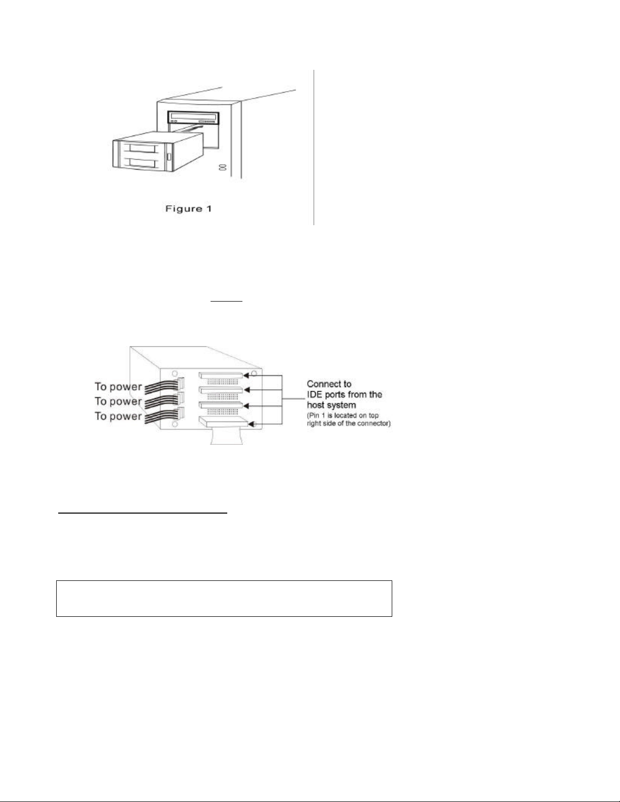
2. Connect the cables as shown in figure 2. When connecting cables to
the IDE bus make sure the numerical pins are lined up with the
connector, else you may damage the hard disk drive.
Figure 2
Installing a hard drive in the disk tray
1. Remove an empty disk tray.
2. Unpack the hard drive. Set the HDD to "Master". Refer to the manufacturer’s
documentation for the location of this jumper .
CAUTION: Static electrical discharge (ESD) can damage your drive or other
components. To avoid ESD, ground yourself by touching any metal on the
subsystem chassis.
3. Connect the power cable to the power connector on the hard drive.
4. Connect the 40-pin ATA cable to the IDE connector on the hard drive.
Align the colored edge of the cable with pin 1 of the connector.
720-0091-00 B QUICK START GUIDE, 3W-RDC-400 Rev March 2003 Page 2 of 4
Page 3

See figure 3.
5. Insert the hard drive into the disk tray.
6. Install the mounting screws on each side to secure the drive in the disk
tray.
7. Slide the tray into a slot until it clicks into place.
8. Insert the key (included in your package) into the keylock located on the
right of the front panel and turn it clockwise. This will lock the disk tray
into the subsystem providing data security and provide power to the drive.
If you are replacing a hard drive, make sure to unlock it by turning the key
counter-clockwise.
NOTE: When the hard drive is being accessed, the HDD activity LED
illuminates.
Hot Add/Removing Disk
The cage supports ‘Hot add and remove’ by turning power off to the drive
when the key is moved to the unlock position. See your controller
documentation for whether or not it supports this feature and for the specific
procedure to accomplish this.
Specifications
Form-factor 5.25” x 3 standard half height drive bays internal mounting
No. of drive channels 4
Hot-swap drive tray 4 each 1” trays
Cooling fan 2
Security locks Yes
Host independent Yes
720-0091-00 B QUICK START GUIDE, 3W-RDC-400 Rev March 2003 Page 3 of 4
Page 4

Drive access indicators Yes
Power requirements 5V DC 3A (Max)
Environmental relative humidity 10% to 85% Non-condensing
Operating Temp 5°C ~ 40°C (41°F ~ 104°F)
Non-operating Temp -40°C ~ 60°C (-40°F ~ 140°F)
Physical dimension 128mm (H) x 149mm (W) x 233.4mm (D)
Weight 2.8kgs / 6.17lbs (without drives)
Copyright
©2003 3ware, Inc. All rights reserved. No part of this publication may be reproduced, stored in a retrieval
system, or transmitted in any form or by any means, electronic, mechanical, photocopying, recording or
otherwise, without the proper written consent of 3ware, Inc., 455 W. Maude Avenue, Sunnyvale CA 94085
Disclaimer
3ware, Inc. assumes no responsibility for errors or omissions in this document, nor does 3ware make any
commitment to update the information contained herein.
Warranty, Technial Support and Service
Limited Warranty
1-year hardware warranty: 3ware, Inc. warrants this product against defects in
material and workmanship for a period of twelve (12) months from the date of
original purchase.
Exclusions
THIS WARRANTY DOES NOT COVER ANY DAMAGE TO THIS PRODUCT WHICH
RESULTS FORM ACCIDENT, ABUSE, MISUSE, NATURAL OR PERSONAL DISASTER,
OR ANY UNAUTHORIZED DISASSEMBLY, REPAIR OR MODIFICATION. 3WARE
SHALL NOT BE LIABLE FOR ANY INCIDENTAL OR CONSEQUENTIAL DAMAGES,
INCLUDING BUT NOT LIMITED TO LOSS OF PROFITS, OTHER LOSS, DAMAGE OR
EXPENSE DIRECTLY OR INDIRECTLY ARISING FROM THE CUSTOMER’S MISUSE
OF OR INABILITY TO USE THE PRODUCT, EITHER SEPARATELY OR IN
COMBINATION WITH OTHER EQUIPMENT, REGARDLESS OF WHETHER 3WARE
HAS BEEN ADVISED OF THE POSSIBILITY OF SUCH DAMAGES. 3WARE IS NOT
LIABLE FOR, AND DOES NOT COVER UNDER WARRANTY, ANY COSTS
ASSOCIATED WITH SERVICING AND/OR THE INSTALLATION OF 3WARE
PRODUCTS. THIS WARRANTY SETS FOR THE ENTIRE LIABILITY AND
OBLIGATIONS OF 3WARE WITH RESPECT TO BREACH OF WARRANTY, AND THE
WARRANTIES SET FORTH OR LIMITED HEREIN ARE THE SOLE WARRANTIES AND
ARE IN LIEU OF ALL OTHER WARRANTIES, EXPRESSED OR IMPLIED, INCLUDING
WARRANTIES OR FITNESS FOR PARTICULAR PURPOSE AND MERCHANTABILITY.
State Law Provisions
This warranty gives you specific legal rights and you may have other rights which
vary from state to state. Some states do not allow the exclusion of incidental or
consequential damages or allow limitation of implied warranties or their duration,
so that the above exclusions or limitations may not apply.
3ware Technical Support and Services
Please call 3ware toll free at (877)883-9273 or email to support@3ware.com to
obtain RMA number to return.
3ware Address
455 W. Maude Avenue, Sunnyvale CA 94085
720-0091-00 B QUICK START GUIDE, 3W-RDC-400 Rev March 2003 Page 4 of 4
 Loading...