

Page 1
User Guide
3ware
®
Serial ATA RAID Controller
Supports the 9650SE, 9590SE, and 9550SX Models
PN 720-0159-00
March 2007
Page 2

Copyright
©2004-2007 Applied Micro Circuits Corporation (AMCC). All rights
reserved. This publication may be copied or reproduced for reference
purposes only. All other purposes require the express written consent of
AMCC, 215 Moffett Park Drive, Sunnyvale, CA 94089. AMCC shall not be
responsible or liable for, and shall be held harmless against, any and all
damages, claims, and/or disputes that arise from the copying or reproduction
of this publication.
Trademarks
3ware®, Escalade®, 3DM®, and TwinStor® are all registered trademarks of
AMCC. The 3ware logo, 3BM, Multi-Lane, StorSave, StorSwitch,
StreamFusion, and R5 Fusion are all trademarks of AMCC. PowerPC and the
PowerPC logo are trademarks of International Business Machines
Corporation. Linux® is a registered trademark of Linus Torvalds in the
United States, other countries, or both. Windows® is a registered trademark
of Microsoft Corporation in the United States and other countries. Firefox® is
a registered trademark of the Mozilla Foundation. PCI Express® is a
registered trademark of PCI-SIG®. All other trademarks herein are property
of their respective owners.
Disclaimer
While every attempt is made to make this document as accurate as possible,
AMCC assumes no responsibility for errors or omissions in this document,
nor does AMCC make any commitment to update the information contained
herein.
www.3ware.com ii
Page 3

Table of Contents
About this User Guide. . . . . . . . . . . . . . . . . . . . . . . . . . . . . . . . . . . . . . . . vii
How this User Guide is Organized . . . . . . . . . . . . . . . . . . . . . . . . . . . . . . . . . . . . . . .vii
Conventions . . . . . . . . . . . . . . . . . . . . . . . . . . . . . . . . . . . . . . . . . . . . . . . . . . . . . . . . ix
Screenshots . . . . . . . . . . . . . . . . . . . . . . . . . . . . . . . . . . . . . . . . . . . . . . . . . . . . . . . . ix
Using the 3ware HTML Bookshelf . . . . . . . . . . . . . . . . . . . . . . . . . . . . . . . . . . . . . . . ix
Chapter 1. Introducing the 3ware® SATA RAID Controller . . . . . . . . . . . . . . . . . . . . .1
What’s New with 9650SE Models . . . . . . . . . . . . . . . . . . . . . . . . . . . . . . . . . . . . . . . . 1
System Requirements . . . . . . . . . . . . . . . . . . . . . . . . . . . . . . . . . . . . . . . . . . . . . . . . . 2
Understanding RAID Concepts and Levels . . . . . . . . . . . . . . . . . . . . . . . . . . . . . . . . 4
RAID Concepts . . . . . . . . . . . . . . . . . . . . . . . . . . . . . . . . . . . . . . . . . . . . . . . . . . . . 4
Available RAID Configurations . . . . . . . . . . . . . . . . . . . . . . . . . . . . . . . . . . . . . . . . 5
Determining What RAID Level to Use . . . . . . . . . . . . . . . . . . . . . . . . . . . . . . . . . . 11
3ware Tools for Configura tio n and Management . . . . . . . . . . . . . . . . . . . . . . . . . . . 13
Monitoring, Maintenance, and Troubleshooting Features . . . . . . . . . . . . . . . . . . . . . 14
Chapter 2. Getting Started with Your 3ware RAID Controller . . . . . . . . . . . . . . . . . .16
Chapter 3. First-Time RAID Configuration Using 3BM. . . . . . . . . . . . . . . . . . . . . . . .20
Basic Steps for Creating a Unit . . . . . . . . . . . . . . . . . . . . . . . . . . . . . . . . . . . . . . . . . 20
Specifying a Hot Spare . . . . . . . . . . . . . . . . . . . . . . . . . . . . . . . . . . . . . . . . . . . . . . . 28
Leaving Individual Drives as JBODs . . . . . . . . . . . . . . . . . . . . . . . . . . . . . . . . . . . . . 28
Checking the Motherboard Boot Sequence . . . . . . . . . . . . . . . . . . . . . . . . . . . . . . . 29
What Next? . . . . . . . . . . . . . . . . . . . . . . . . . . . . . . . . . . . . . . . . . . . . . . . . . . . . . . . . 29
Chapter 4. Driver Installation . . . . . . . . . . . . . . . . . . . . . . . . . . . . . . . . . . . . . . . . . . . .30
Driver Installation Under Windows . . . . . . . . . . . . . . . . . . . . . . . . . . . . . . . . . . . . . . 31
Materials Required . . . . . . . . . . . . . . . . . . . . . . . . . . . . . . . . . . . . . . . . . . . . . . . . 31
Creating a 3ware Driver Diskette . . . . . . . . . . . . . . . . . . . . . . . . . . . . . . . . . . . . . 32
Installing the 3ware Driver and Windows on a New Unit . . . . . . . . . . . . . . . . . . . . 32
Installing the Driver on a System that Boots from a Different Device . . . . . . . . . . 33
Making Units Managed by a 3ware Controller Available to Windows . . . . . . . . . . 38
Driver Installation Under Linux . . . . . . . . . . . . . . . . . . . . . . . . . . . . . . . . . . . . . . . . . 39
Obtaining 3ware Linux Drivers . . . . . . . . . . . . . . . . . . . . . . . . . . . . . . . . . . . . . . . 40
Driver Installation Under Red Hat Linux or Fedora Core 5 . . . . . . . . . . . . . . . . . . 41
Driver Installation Under SuSE Linux . . . . . . . . . . . . . . . . . . . . . . . . . . . . . . . . . . 47
Compiling a 3ware Driver for Linux . . . . . . . . . . . . . . . . . . . . . . . . . . . . . . . . . . . . 50
Driver Installation Under FreeBSD . . . . . . . . . . . . . . . . . . . . . . . . . . . . . . . . . . . . . . 50
Obtaining 3ware FreeBSD Drivers . . . . . . . . . . . . . . . . . . . . . . . . . . . . . . . . . . . . 51
Installing the Driver under FreeBSD . . . . . . . . . . . . . . . . . . . . . . . . . . . . . . . . . . . 51
Chapter 5. 3ware BIOS Manager 2 (3BM 2) Introduction . . . . . . . . . . . . . . . . . . . . . .57
Starting 3BM 2 . . . . . . . . . . . . . . . . . . . . . . . . . . . . . . . . . . . . . . . . . . . . . . . . . . . . . 57
Exiting the 3BM Configuration Utility . . . . . . . . . . . . . . . . . . . . . . . . . . . . . . . . . . . . 59
Working in the 3BM Screens . . . . . . . . . . . . . . . . . . . . . . . . . . . . . . . . . . . . . . . . . . 60
Adjusting BIOS Loading Settings . . . . . . . . . . . . . . . . . . . . . . . . . . . . . . . . . . . . . . . 63
Displaying Controller Information . . . . . . . . . . . . . . . . . . . . . . . . . . . . . . . . . . . . . . . 65
Getting Help While Using 3BM . . . . . . . . . . . . . . . . . . . . . . . . . . . . . . . . . . . . . . . . . 65
Chapter 6. 3DM 2 (3ware Disk Manager) Introduction . . . . . . . . . . . . . . . . . . . . . . . .66
Browser Requirements for 3DM . . . . . . . . . . . . . . . . . . . . . . . . . . . . . . . . . . . . . . . . 67
Installing 3DM . . . . . . . . . . . . . . . . . . . . . . . . . . . . . . . . . . . . . . . . . . . . . . . . . . . . . . 68
www.3ware.com iii
Page 4

Starting 3DM and Logging In . . . . . . . . . . . . . . . . . . . . . . . . . . . . . . . . . . . . . . . . . . 68
Logging In to the 3DM Web Application . . . . . . . . . . . . . . . . . . . . . . . . . . . . . . . . 68
Starting the 3DM Daemon under Linux and FreeBSD . . . . . . . . . . . . . . . . . . . . . 70
Starting the 3DM Process under Microsoft Windows . . . . . . . . . . . . . . . . . . . . . . 70
Viewing 3DM Remotely Using a Web Browser . . . . . . . . . . . . . . . . . . . . . . . . . . . 71
Working with the 3DM Screens . . . . . . . . . . . . . . . . . . . . . . . . . . . . . . . . . . . . . . . . . 71
3DM Menus . . . . . . . . . . . . . . . . . . . . . . . . . . . . . . . . . . . . . . . . . . . . . . . . . . . . . . 72
Viewing Information Abou t D ifferent Controllers . . . . . . . . . . . . . . . . . . . . . . . . . . 74
Refreshing the Screen . . . . . . . . . . . . . . . . . . . . . . . . . . . . . . . . . . . . . . . . . . . . . 74
3DM Screens and What They're Used For . . . . . . . . . . . . . . . . . . . . . . . . . . . . . . 74
Setting Up 3DM Preferences . . . . . . . . . . . . . . . . . . . . . . . . . . . . . . . . . . . . . . . . . . 76
Setting and Changing 3DM Passwords . . . . . . . . . . . . . . . . . . . . . . . . . . . . . . . . 77
Managing E-mail Event Notification . . . . . . . . . . . . . . . . . . . . . . . . . . . . . . . . . . . 77
Enabling and Disabling Remote Access . . . . . . . . . . . . . . . . . . . . . . . . . . . . . . . . 78
Setting the Incoming Port # . . . . . . . . . . . . . . . . . . . . . . . . . . . . . . . . . . . . . . . . . . 79
Setting the Frequency of Page Refreshes . . . . . . . . . . . . . . . . . . . . . . . . . . . . . . 79
Chapter 7. Configuring Your Controller. . . . . . . . . . . . . . . . . . . . . . . . . . . . . . . . . . . .80
Viewing Information About a Controller . . . . . . . . . . . . . . . . . . . . . . . . . . . . . . . . . . 80
About Controller Policies . . . . . . . . . . . . . . . . . . . . . . . . . . . . . . . . . . . . . . . . . . . . . 82
Viewing Controller Policies . . . . . . . . . . . . . . . . . . . . . . . . . . . . . . . . . . . . . . . . . . . . 83
Setting the Auto Rebuild Policy . . . . . . . . . . . . . . . . . . . . . . . . . . . . . . . . . . . . . . . . 85
Using Auto-Carving for Multi LUN Support . . . . . . . . . . . . . . . . . . . . . . . . . . . . . . . . 86
Setting the Size of Volumes Created with Auto-Carving . . . . . . . . . . . . . . . . . . . . . . 88
Enabling and Setting Up Staggered Spin-up . . . . . . . . . . . . . . . . . . . . . . . . . . . . . . 89
Exporting JBOD Disks . . . . . . . . . . . . . . . . . . . . . . . . . . . . . . . . . . . . . . . . . . . . . . . 90
Chapter 8. Configuring Units . . . . . . . . . . . . . . . . . . . . . . . . . . . . . . . . . . . . . . . . . . . .91
Configuring a New Unit . . . . . . . . . . . . . . . . . . . . . . . . . . . . . . . . . . . . . . . . . . . . . . . 91
Configuration Options When Creating a Unit . . . . . . . . . . . . . . . . . . . . . . . . . . . . 92
Creating a Unit through 3DM . . . . . . . . . . . . . . . . . . . . . . . . . . . . . . . . . . . . . . . . 94
Creating a Unit through 3BM . . . . . . . . . . . . . . . . . . . . . . . . . . . . . . . . . . . . . . . . . 97
Ordering Units in 3BM . . . . . . . . . . . . . . . . . . . . . . . . . . . . . . . . . . . . . . . . . . . . . 100
Partitioning, Formatting, and Mounting Units . . . . . . . . . . . . . . . . . . . . . . . . . . . 101
Creating a Hot Spare . . . . . . . . . . . . . . . . . . . . . . . . . . . . . . . . . . . . . . . . . . . . . . . 103
Specifying a Hot Spare through 3DM . . . . . . . . . . . . . . . . . . . . . . . . . . . . . . . . . 104
Specifying a Hot Spare through 3BM . . . . . . . . . . . . . . . . . . . . . . . . . . . . . . . . . 104
Naming a Unit . . . . . . . . . . . . . . . . . . . . . . . . . . . . . . . . . . . . . . . . . . . . . . . . . . . . . 105
Setting Unit Policies . . . . . . . . . . . . . . . . . . . . . . . . . . . . . . . . . . . . . . . . . . . . . . . . 106
Enabling and Disabling the Unit Write Cache . . . . . . . . . . . . . . . . . . . . . . . . . . . 108
Setting Auto Verify for a Unit . . . . . . . . . . . . . . . . . . . . . . . . . . . . . . . . . . . . . . . . 109
Setting Continue on Source Error During Rebuild . . . . . . . . . . . . . . . . . . . . . . . 110
Enabling and Disabling Queuing for a Unit . . . . . . . . . . . . . . . . . . . . . . . . . . . . . .111
Setting the StorSave Profile for a Unit . . . . . . . . . . . . . . . . . . . . . . . . . . . . . . . . . 112
Changing An Existing Configuration by Migrating . . . . . . . . . . . . . . . . . . . . . . . . . 115
RAID Level Migration (RLM) Overview . . . . . . . . . . . . . . . . . . . . . . . . . . . . . . . . 116
Changing RAID Level . . . . . . . . . . . . . . . . . . . . . . . . . . . . . . . . . . . . . . . . . . . . . 117
Expanding Unit Capacity . . . . . . . . . . . . . . . . . . . . . . . . . . . . . . . . . . . . . . . . . . . 118
Informing the Operating System of Changed Configuration . . . . . . . . . . . . . . . . 119
Deleting a Unit . . . . . . . . . . . . . . . . . . . . . . . . . . . . . . . . . . . . . . . . . . . . . . . . . . . . 120
Deleting a Unit through 3DM . . . . . . . . . . . . . . . . . . . . . . . . . . . . . . . . . . . . . . . . 121
Deleting a Unit through 3BM . . . . . . . . . . . . . . . . . . . . . . . . . . . . . . . . . . . . . . . . 122
Removing a Unit . . . . . . . . . . . . . . . . . . . . . . . . . . . . . . . . . . . . . . . . . . . . . . . . . . . 123
Removing a Unit Through 3DM . . . . . . . . . . . . . . . . . . . . . . . . . . . . . . . . . . . . . . 124
Removing a Unit Through 3BM . . . . . . . . . . . . . . . . . . . . . . . . . . . . . . . . . . . . . . 125
Moving a Unit from One Controller to Another . . . . . . . . . . . . . . . . . . . . . . . . . . . . 126
iv 3ware Serial ATA RAID Controller User Guide
Page 5

Moving Units from an 8000 Controller to a 9000 Controller . . . . . . . . . . . . . . . . 126
Moving Legacy JBOD Units to a 9000 Controller . . . . . . . . . . . . . . . . . . . . . . . . 127
Moving Units from a 9500S to a 9550SX, 9590SE, or 9650SE Controller . . . . . 128
Adding a Drive . . . . . . . . . . . . . . . . . . . . . . . . . . . . . . . . . . . . . . . . . . . . . . . . . . . . 129
Removing a Drive . . . . . . . . . . . . . . . . . . . . . . . . . . . . . . . . . . . . . . . . . . . . . . . . . . 130
Rescanning the Controller . . . . . . . . . . . . . . . . . . . . . . . . . . . . . . . . . . . . . . . . . . . 131
Chapter 9. Maintaining Units . . . . . . . . . . . . . . . . . . . . . . . . . . . . . . . . . . . . . . . . . . .133
Checking Unit and Drive Status through 3DM . . . . . . . . . . . . . . . . . . . . . . . . . . . . 133
Enclosure LED Status Indicators . . . . . . . . . . . . . . . . . . . . . . . . . . . . . . . . . . . . . 135
Unit Statuses . . . . . . . . . . . . . . . . . . . . . . . . . . . . . . . . . . . . . . . . . . . . . . . . . . . . 135
Drive Statuses . . . . . . . . . . . . . . . . . . . . . . . . . . . . . . . . . . . . . . . . . . . . . . . . . . . 137
About Degraded Units . . . . . . . . . . . . . . . . . . . . . . . . . . . . . . . . . . . . . . . . . . . . . . . 137
About Inoperable Units . . . . . . . . . . . . . . . . . . . . . . . . . . . . . . . . . . . . . . . . . . . . . . 138
Alarms, Errors, and Other Events . . . . . . . . . . . . . . . . . . . . . . . . . . . . . . . . . . . . . . 138
Viewing Alarms, Errors, and Other Events . . . . . . . . . . . . . . . . . . . . . . . . . . . . . 138
Using the Alert Utility Under Windows . . . . . . . . . . . . . . . . . . . . . . . . . . . . . . . . 139
Downloading an Error Log . . . . . . . . . . . . . . . . . . . . . . . . . . . . . . . . . . . . . . . . . 141
Viewing SMART Data About a Drive . . . . . . . . . . . . . . . . . . . . . . . . . . . . . . . . . . 141
Background Tasks . . . . . . . . . . . . . . . . . . . . . . . . . . . . . . . . . . . . . . . . . . . . . . . . . 142
About Initialization . . . . . . . . . . . . . . . . . . . . . . . . . . . . . . . . . . . . . . . . . . . . . . . . 143
About Verification . . . . . . . . . . . . . . . . . . . . . . . . . . . . . . . . . . . . . . . . . . . . . . . . 146
Starting a Verify Manually . . . . . . . . . . . . . . . . . . . . . . . . . . . . . . . . . . . . . . . . . . 148
Rebuilding Units . . . . . . . . . . . . . . . . . . . . . . . . . . . . . . . . . . . . . . . . . . . . . . . . . 150
Cancelling a Rebuild and Restarting It with a Different Drive . . . . . . . . . . . . . . . 154
Setting Background Task Rate . . . . . . . . . . . . . . . . . . . . . . . . . . . . . . . . . . . . . . 155
Background Task Prioritization . . . . . . . . . . . . . . . . . . . . . . . . . . . . . . . . . . . . . . 156
Scheduling Background Tasks . . . . . . . . . . . . . . . . . . . . . . . . . . . . . . . . . . . . . . . . 156
Viewing Current Task Schedules . . . . . . . . . . . . . . . . . . . . . . . . . . . . . . . . . . . . . 157
Turning On or Off Use of a Task Schedule . . . . . . . . . . . . . . . . . . . . . . . . . . . . . 158
Removing a Task Schedule . . . . . . . . . . . . . . . . . . . . . . . . . . . . . . . . . . . . . . . . . 159
Adding a New Task Schedule Slot . . . . . . . . . . . . . . . . . . . . . . . . . . . . . . . . . . . 159
Selecting Self-tests to be Performed . . . . . . . . . . . . . . . . . . . . . . . . . . . . . . . . . . 160
Locating a Drive by Blinking Its LED . . . . . . . . . . . . . . . . . . . . . . . . . . . . . . . . . . . . 161
Chapter 10. Maintaining Your Controller. . . . . . . . . . . . . . . . . . . . . . . . . . . . . . . . . . .163
Determining the Current Version of Your 3ware Driver . . . . . . . . . . . . . . . . . . . . . . 163
Updating the Firmware and Driver . . . . . . . . . . . . . . . . . . . . . . . . . . . . . . . . . . . . . 164
Downloading the Driver and F i rmw are . . . . . . . . . . . . . . . . . . . . . . . . . . . . . . . . 165
Updating the Firmware Through 3DM 2 . . . . . . . . . . . . . . . . . . . . . . . . . . . . . . . 166
Updating the 3ware Driver and Firmware Under Windows . . . . . . . . . . . . . . . . . 167
Using the Update Utility With Multiple Controllers . . . . . . . . . . . . . . . . . . . . . . . . 171
Updating the 3ware Driver Under Windows XP . . . . . . . . . . . . . . . . . . . . . . . . . 172
Updating the 3ware Driver Under Red Hat or Fedora Core . . . . . . . . . . . . . . . . 178
Updating the 3ware Driver Under SuSE . . . . . . . . . . . . . . . . . . . . . . . . . . . . . . . 179
Updating the 3ware Driver Under FreeBSD . . . . . . . . . . . . . . . . . . . . . . . . . . . . 181
Updating the Firmware Under Linux and FreeBSD . . . . . . . . . . . . . . . . . . . . . . . 182
Viewing Battery Information . . . . . . . . . . . . . . . . . . . . . . . . . . . . . . . . . . . . . . . . . . 183
Testing Battery Capacity . . . . . . . . . . . . . . . . . . . . . . . . . . . . . . . . . . . . . . . . . . . . . 183
Chapter 11. 3DM 2 Reference . . . . . . . . . . . . . . . . . . . . . . . . . . . . . . . . . . . . . . . . . . . .186
Controller Summary page . . . . . . . . . . . . . . . . . . . . . . . . . . . . . . . . . . . . . . . . . . . . 187
Controller Details page . . . . . . . . . . . . . . . . . . . . . . . . . . . . . . . . . . . . . . . . . . . . . . 188
Unit Information page . . . . . . . . . . . . . . . . . . . . . . . . . . . . . . . . . . . . . . . . . . . . . . . 189
Unit Details page . . . . . . . . . . . . . . . . . . . . . . . . . . . . . . . . . . . . . . . . . . . . . . . . . . . 190
Drive Information page . . . . . . . . . . . . . . . . . . . . . . . . . . . . . . . . . . . . . . . . . . . . . . 192
www.3ware.com v
Page 6

Drive Details window . . . . . . . . . . . . . . . . . . . . . . . . . . . . . . . . . . . . . . . . . . . . . . . . 193
Controller Settings page . . . . . . . . . . . . . . . . . . . . . . . . . . . . . . . . . . . . . . . . . . . . . 195
Scheduling page . . . . . . . . . . . . . . . . . . . . . . . . . . . . . . . . . . . . . . . . . . . . . . . . . . . 199
Maintenance page . . . . . . . . . . . . . . . . . . . . . . . . . . . . . . . . . . . . . . . . . . . . . . . . . 202
Alarms page . . . . . . . . . . . . . . . . . . . . . . . . . . . . . . . . . . . . . . . . . . . . . . . . . . . . . . 210
Battery Backup page . . . . . . . . . . . . . . . . . . . . . . . . . . . . . . . . . . . . . . . . . . . . . . . . 211
Enclosure Summary page . . . . . . . . . . . . . . . . . . . . . . . . . . . . . . . . . . . . . . . . . . . . 213
Enclosure Details page . . . . . . . . . . . . . . . . . . . . . . . . . . . . . . . . . . . . . . . . . . . . . . 214
3DM 2 Settings page . . . . . . . . . . . . . . . . . . . . . . . . . . . . . . . . . . . . . . . . . . . . . . . 215
Chapter 12. Troubleshooting . . . . . . . . . . . . . . . . . . . . . . . . . . . . . . . . . . . . . . . . . . . .218
Web Resources . . . . . . . . . . . . . . . . . . . . . . . . . . . . . . . . . . . . . . . . . . . . . . . . . . . 218
Before Contacting Customer Su pp o rt . . . . . . . . . . . . . . . . . . . . . . . . . . . . . . . . . . . 219
Basic Troubleshooting: Check This First . . . . . . . . . . . . . . . . . . . . . . . . . . . . . . . . 219
Command Logging . . . . . . . . . . . . . . . . . . . . . . . . . . . . . . . . . . . . . . . . . . . . . . . . . 220
Problems and Solutions . . . . . . . . . . . . . . . . . . . . . . . . . . . . . . . . . . . . . . . . . . . . . 220
Enclosure-Related Problems . . . . . . . . . . . . . . . . . . . . . . . . . . . . . . . . . . . . . . . 221
Hardware Installation Problems . . . . . . . . . . . . . . . . . . . . . . . . . . . . . . . . . . . . . 221
Software Installation Problems . . . . . . . . . . . . . . . . . . . . . . . . . . . . . . . . . . . . . . 222
Problems in 3DM and 3BM . . . . . . . . . . . . . . . . . . . . . . . . . . . . . . . . . . . . . . . . . 223
Error and Notification Messages . . . . . . . . . . . . . . . . . . . . . . . . . . . . . . . . . . . . . . . 224
Error and Notification Message Details . . . . . . . . . . . . . . . . . . . . . . . . . . . . . . . . 227
Appendices . . . . . . . . . . . . . . . . . . . . . . . . . . . . . . . . . . . . . . . . . . . . . . . .264
Installing Software from a Graphical User Interface (GUI) . . . . . . . . . . . . . . . . . . . 271
Installing Software on Linux and FreeBSD from the Command Line . . . . . . . . . . . 278
Uninstalling Software . . . . . . . . . . . . . . . . . . . . . . . . . . . . . . . . . . . . . . . . . . . . . . . 279
Uninstalling 3DM under Microsoft Windows . . . . . . . . . . . . . . . . . . . . . . . . . . . . 279
Uninstalling 3DM under Linux or FreeBSD . . . . . . . . . . . . . . . . . . . . . . . . . . . . . 279
FCC Radio Frequency Interference Statement . . . . . . . . . . . . . . . . . . . . . . . . . . . . 280
Microsoft Windows Hardware Quality Lab . . . . . . . . . . . . . . . . . . . . . . . . . . . . . . . 281
European Community Conformity Statement . . . . . . . . . . . . . . . . . . . . . . . . . . . . . 281
Limited Warranty . . . . . . . . . . . . . . . . . . . . . . . . . . . . . . . . . . . . . . . . . . . . . . . . . . . 282
Warranty Service and RMA Process . . . . . . . . . . . . . . . . . . . . . . . . . . . . . . . . . . . 283
AMCC Technical Support and Services . . . . . . . . . . . . . . . . . . . . . . . . . . . . . . . . . 284
Sales and ordering information . . . . . . . . . . . . . . . . . . . . . . . . . . . . . . . . . . . . . . . . 284
Feedback on this manual . . . . . . . . . . . . . . . . . . . . . . . . . . . . . . . . . . . . . . . . . . . . 284
Index . . . . . . . . . . . . . . . . . . . . . . . . . . . . . . . . . . . . . . . . . . . . . . . . . . . . .285
vi 3ware Serial ATA RAID Controller User Guide
Page 7

About this User Guide
This document, 3ware Serial ATA RAID Controller User Guide, provides
instructions for configuring and maintaining RAID units on 3ware 9650SE,
9590SE, and 9550SX series RAID controllers.
This guide assumes that you have already installed your controller and drives
in your system, and set up your 3ware Sidecar, if you have one. If you have
not yet done so, see the installation guide that came with your controller. If
you do not have the printed copy, an PDF of the installation guide is available
on your 3ware CD, or you can download it from: http://www.3ware.com/
support/userdocs.asp. (Note that there are different installation guides for
different 3ware RAID controller models.)
There are often multiple ways to accomplish the same configuration and
maintenance tasks for your 3ware RAID controller. This manual includes
instructions for performing tasks using two tools: one at the BIOS level
(3ware BIOS Manager 2, referred to as 3BM 2) and one that runs in a browser
(3ware Disk Manager 2, referred to as 3DM 2).
You can also perform many tasks at the command line, using 3ware’s
Command Line Interface (CLI). The CLI is described in a separate manual:
3ware Serial ATA RAID Controller CLI Guide. Information from both this
Users Guide and the CLI Guide are also available in the 3ware HTML
Bookshelf, available in the 3ware Documentation folder and on your 3ware
CD. (For more information, see “Using the 3ware HTML Bookshelf” on
page ix.)
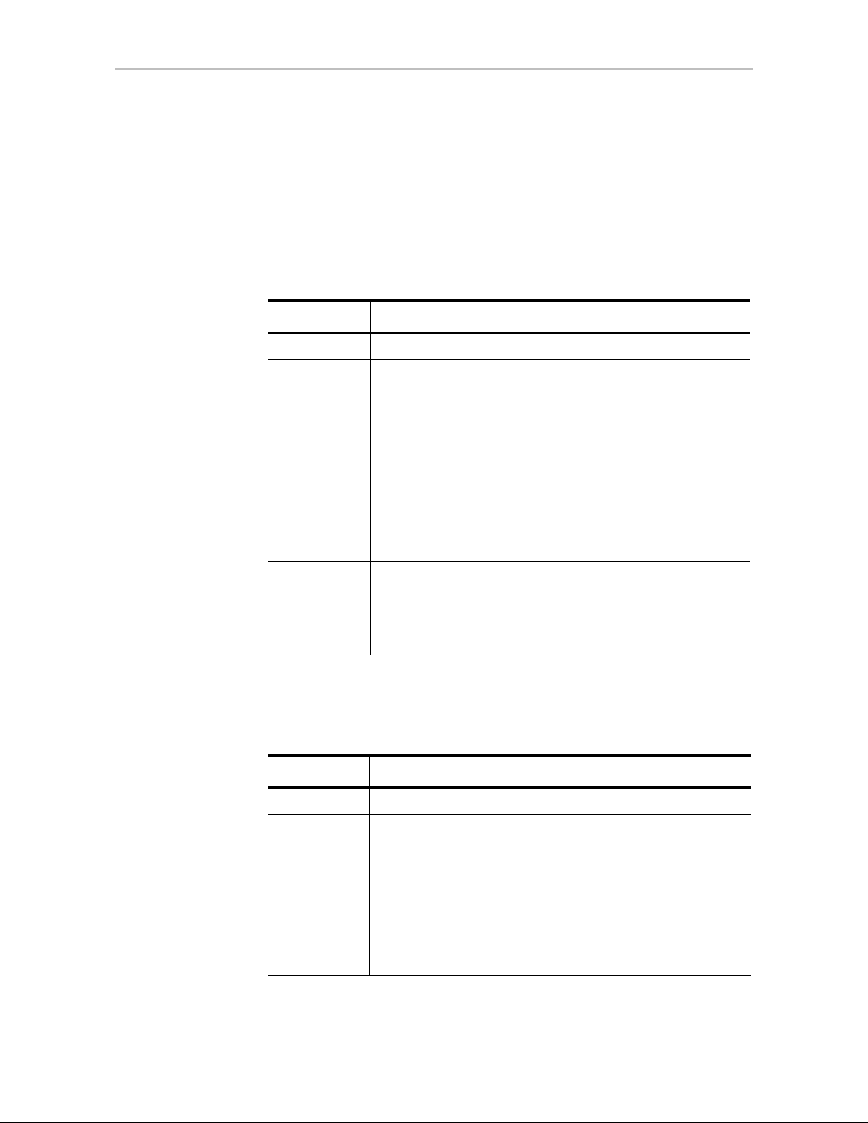
How this User Guide is Organized
Table 1: Chapters and Appendices in this Guide
Chapter/Appendix Description
1. Introduction Provides an overview of product features for
the 3ware 9650SE, 9590SE, and 9550SX
controller models. Includes system
requirements and an introduction to RAID
concepts and levels.
vii 3ware Serial ATA RAID Controller User Guide
Page 8
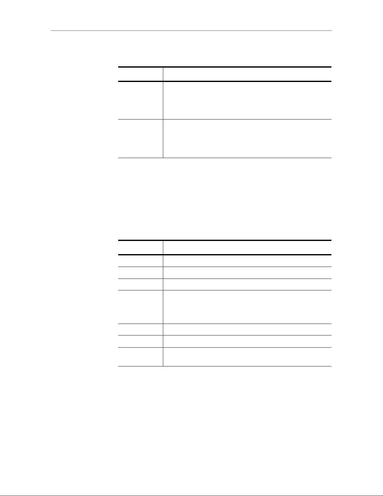
Table 1: Chapters and Appendices in this Guide
Chapter/Appendix Description
2. Getting Started Provides a summary of the process you should
follow to get started using your 3ware RAID
controller.
3. First-Time RAID Configuration
Using 3BM
4. Driver Installation Describes how to install drivers for the 3ware
5. 3ware BIOS Manager (3BM) Describes the basics of using 3BM.
6. 3ware Disk Manager 2
(3DM 2)
7. Configuring Your Controller Describes how to view details about the
8. Configuring Units Describes how to configure new units and hot
9. Maintaining Units Describes how to check unit and drive status,
10. Maintaining Your Controller Describes how to update the driver, move a unit
Provides step-by-step instructions for
configuring RAID units if you have just installed
the controller.
controller if you have just installed and
configured it. Includes information for Windows,
Linux, and FreeBSD.
Describes the basics of using 3DM. Also
includes information about installing and
uninstalling 3DM, and how to start the 3DM
process manually, if required.
controller, check its status, and change
configuration settings that affect the controller
and all associated drives.
spares, change existing configurations, and set
unit policies.
review alarms and errors, schedule background
maintenance tasks, and manually start them,
when necessary or desirable. Includes
explanations of initialization, verify, rebuild, and
self-tests.
from one controller to another, and replace an
existing 3ware controller with a new one. Also
includes information about checking battery
status on a BBU (Battery Backup Unit).
11. 3DM 2 Reference Describes the features and functions on each
of the pages in 3DM.
12. Troubleshooting Provides common problems and solutions, and
explains error messages.
A. Glossary Includes definitions for terms used throughout
this guide.
B. Software Installation Provides instructions for installing software
management tools (3DM 2, CLI, tw_update)
and documentation.
C. Compliance and Conformity
Statements
Provides compliance and conformity statement.
viii 3ware Serial ATA RAID Controller User Guide
Page 9

Table 1: Chapters and Appendices in this Guide
Chapter/Appendix Description
Conventions
D. Warranty, Technical Support,
Conventions
The following conventions are used through this guide:
• 3BM and 3BM 2 both refer to the 3ware BIOS Manager, version 2.
• 3DM and 3DM 2 both refer to the 3ware Disk Manager, version 2.
• In the sections that describe using 3DM, current controller is used to refer
• Unit refers to one or more disks configured through 3ware to be treated by
• Boldface is used for buttons, fields, and settings that appear on the screen.
•
Screenshots
The screenshots in this documentation are examples only, and may not exactly
reflect the operating system and browser you are using. 3ware software works
on a number of different operating systems, including Mac OS X, Microsoft
Windows®, Linux®, and FreeBSD®, and runs in a number of different
browsers. In addition, the version shown in screenshots may not match your
version. For the current released and tested version number, see the latest
release notes.
Provides warranty information and tells you
and Service
to the controller which is currently selected in this drop-down list.
the operating system as a single drive. Also known as an array. Array and
unit are used interchangeably throughout this manual.
Monospace font is used for code and to indicate things you type.
how to contact technical support.
Using the 3ware HTML Bookshelf
The 3ware HTML Bookshelf is an HTML version of this user guide and the
CLI Guide, combined as one resource. It is available on your 3ware CD, in the
/doc folder.
To make use of the 3ware HTML Bookshelf
1 Copy the compressed version of the guide (3wareHTMLBookshelf.zip or
3wareHTMLBookshelf.tgz, depending on your operating system) to a
local drive on your computer and extract it.
www.3ware.com ix
Page 10
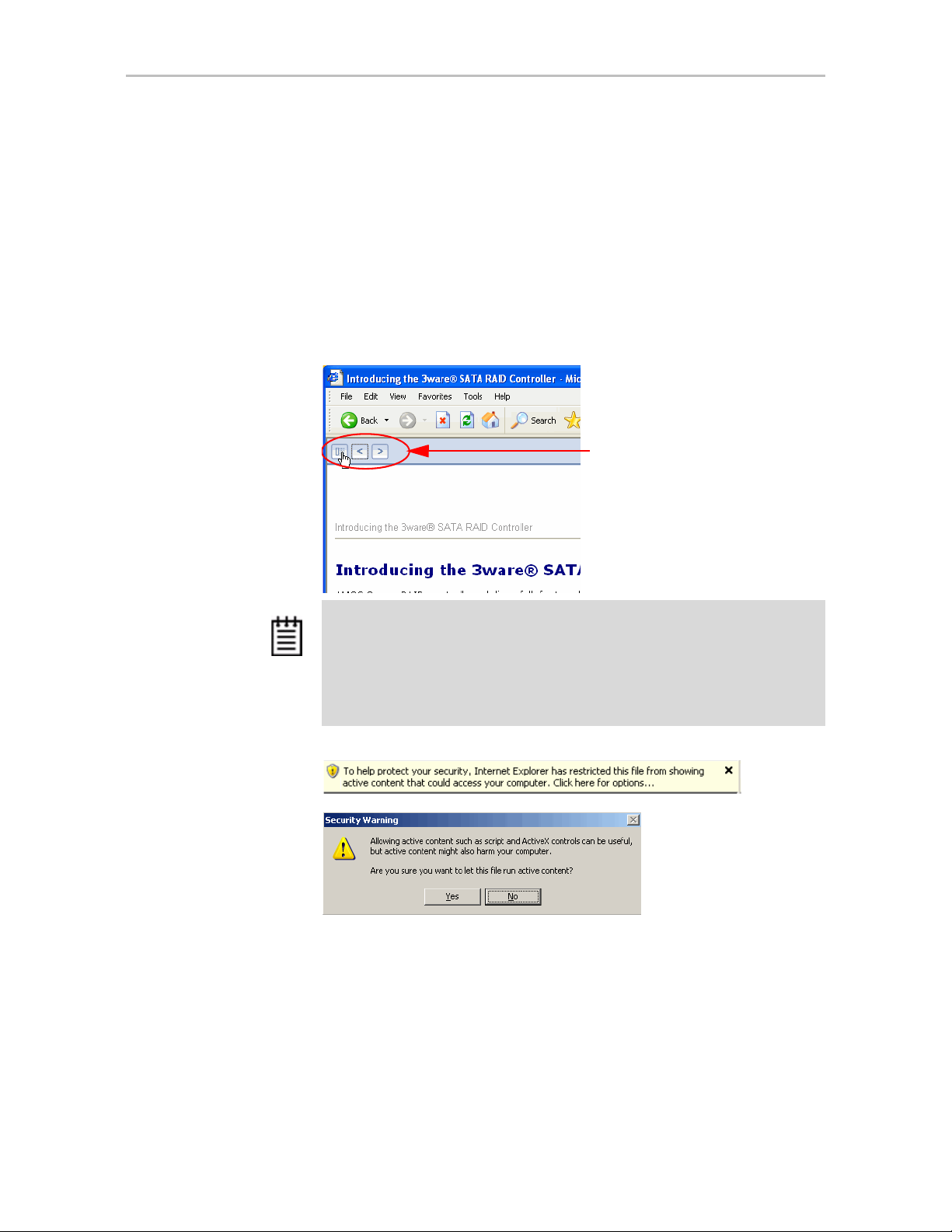
2 To launch the bookshelf at the opening page, open the
3wareHTMLBookshelf folder and double click the file index.html.
Opening the file from “index.html” automatically displays a navigation
panel at the left that includes a Table of Contents, Index, and Search.
You can also open the bookshelf by double-clicking any other html file in
the 3wareHTMLBookshelf folder. When you open an individual file, the
navigation pane does not automatically open. In this case, you can display
the navigation pane by clicking the
Figure 1. Navigation Button in the 3ware HTML Bookshelf Window
Show Navigation button at the left.
Click the Show Navigation
button to display the Table of
Contents
Note: The 3ware HTML Bookshelf is created as a set of HTML documents
that are often displayed from a website. When installed on your personal
computer, some browsers flag them as “active content,” and require your
approval before displaying the content.
If you see messages similar to the following, you must confirm the display of
active content in order to see the pages.
x 3ware Serial ATA RAID Controller User Guide
Page 11

1
Introducing the 3ware® SATA RAID Controller
AMCC 3ware RAID controllers deliver full-featured, true hardware RAID to
servers and workstations. AMCC's RAID controllers offer Serial AT A (SAT A)
and SATA II interfaces in both low profile and full-height footprints.
Combined with an advanced RAID management feature set that includes
web-based, command-based, and API (application programming interface)
software components, AMCC controllers, available in 2-, 4-, 8-, 12-, 16-, and
24-port configurations, provide compelling RAID solutions.
This section introduces the features and concepts of AMCC 3ware RAID
controllers. It is organized into the following topics:
• What’s New with 9650SE Models
• System Requirements
• Understanding RAID Concepts and Levels
• 3ware Tools for Configuration and Management
• Monitoring, Maintenance, and Troubleshooting Features
What’s New with 9650SE Models
The 9650SE models in 3ware’s 9000 series of RAID controllers have the
following features and benefits:
• Simultaneous RAID 6 parity generation to maximize RAID 6
performance
• 8th-generation StorSwitch™ non-blocking switch fabric for maximum
controller output
• StreamFusion™ optimizes RAID 5 and RAID 6 disk accesses to
maximize application performance under heavy loads
• StorSave™ BBU with write journaling optimizes data protection and
performance
• RAID levels 0, 1, 5, 6, 10, 50, Single Disk, and JBOD
1 3ware Serial ATA RAID Controller User Guide
Page 12
Chapter 1. Introducing the 3ware® SATA RAID Controller
(RAID 6 and RAID 50 are available only with 3ware RAID controller
models that have 8 or more ports)
• Choice of 2, 4, 8, 12, 16, or 24 SATA ports
• PCI Express® x1, x4 and x8 connectivity
• If you have a 3ware Sidecar, the drive Locate feature allows you to easily
identify a drive in the enclosure by blinking the LED associated with it
System Requirements
3ware 9650SE, 9590SE, and 9550SX model RAID controllers have the
following requirements:
Motherboard and Slot Requirements
A workstation-class or server-class motherboard, with slots that support the
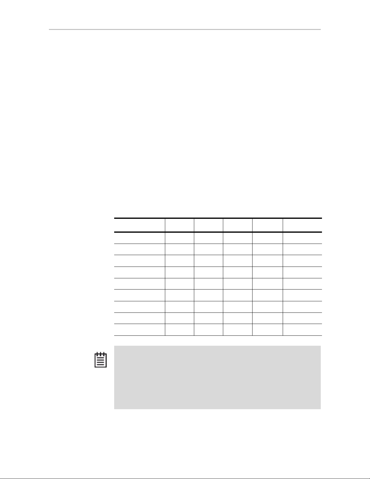
specific 3ware RAID controller model, as shown in Table 2.
Table 2: Required Slots for 3ware RAID Controller Models
Controller Model PCI-E X1 PCI-E X4 PCI-E X8 PCI-E x16 PCI-X (64-bit)
9650SE-2LPML Y
9650SE-4LPML N
9650SE-4LPME N
9650SE-8LPML N
9650SE-12ML N
9650SE-16ML N
9650SE-24M8 N
9590SE N
9550SX N
ES YES YES Yes No
O YES YES Yes No
O YES YES Yes No
O YES YES Yes No
O NO YES Yes No
O NO YES Yes No
O NO YES Yes No
O YES YES Yes No
O NO NO No Yes
Notes:
3ware 9650SE and 9590SE RAID controllers must be installed in a PCI Express
slot that complies with PCI 1.1 or later standards.
The 3ware 9550SX Controller performs best when installed in a PCI-X 133MHz 64bit slot. However, it can also operate at 66MHz or 100MHz.
PCI Slots used for the 9550SX controllers must comply with PCI 2.2 or later
standards and must meet the Plug and Play and PC99 specifications.
2 3ware Serial ATA RAID Controller User Guide
Page 13

System Requirements
Drive Requirements
Depending on the particular model, the 3ware RAID controller may be
connected to two, four, eight, twelve, sixteen, or twenty-four SATA drives
using the supplied interface cables.
Drives must meet SATA-1 (1.5 GB/s) or SATA-2 (3.0 Gb/s) standards.
A list of drives that have been tested is available at
http://www.3ware.com/products/compatibility_sata2.asp
Drives may be of any capacity or physical form factor.
The length of shielded and unshielded interface cables may not exceed 1M
(39”) for Serial ATA controllers.
Operating System
• 3ware RAID controllers may be used with:
• Windows 2000, Windows XP, Windows Server 2003, both 32-bit and 64-
bit x86
• Red Hat Linux, 32-bit and 64-bit x86
• SuSE Linux, 32-bit and 64-bit x86
• Fedora Core, 32-bit and 64-bit x86
• Other versions of Linux, 32-bit and 64-bit x86, using the open source
Linux 2.4 or 2.6 kernel driver
• FreeBSD, 32-bit and 64-bit x86
For the latest driver versions for all operating systems, see the current Release
Notes at http://www.3ware.com/support/.
Other Requirements
• Adequate air flow and cooling
• Adequate power supply for drives
• 3DM 2 (3ware Disk Manager) displays information in a browser. It
requires one of the following browsers:
• Internet Explorer 5.5 and later
• Mozilla Firefox 1.2 and later
• Netscape 7 and later
In addition:
• JavaScript must be enabled
• Cookies must be enabled
www.3ware.com 3
Page 14

Chapter 1. Introducing the 3ware® SATA RAID Controller
• For best viewing, screen resolution should be 1024 x 768 or greater,
with 16-bit color or greater.
For a complete listing of features and system requirements, refer to the 3ware
SATA RAID Controller datasheets, available from the website at http://
www.3ware.com/products.
Understanding RAID Concepts and Levels
3ware RAID controllers use RAID (Redundant Array of Inexpensive Disks)
to increase your storage system’s performance and provide fault tolerance
(protection against data loss).
This section organizes information about RAID concepts and configuration
levels into the following topics:
• “RAID Concepts” on page 4
• “Available RAID Configurations” on page 5
• “Determining What RAID Level to Use” on page 11
RAID Concepts
The following concepts are important to understand when working with a
RAID controller:
•
•
•
Arrays and Units. In the storage industry, the term “array” is used to
describe two or more disk drives that appear to the operating system as a
single unit. When working with a 3ware RAID controller, “unit” is the
term used to refer to an array of disks that is configured and managed
through the 3ware software. Single-disk units can also be configured in
the 3ware software.
Mirroring. Mirrored arrays (RAID 1) write data to paired drives
simultaneously . If one drive fails, the data is preserved on the paired
drive. Mirroring provides data protection through redundancy. In
addition, mirroring using a 3ware RAID controller provides improved
performance because 3ware’s TwinStor technology reads from both
drives simultaneously.
Striping. Striping across disks allows data to be written and accessed on
more than one drive, at the same time. Striping combines each drive’s
capacity into one large volume. Striped disk arrays (RAID 0) achieve
highest transfer rates and performance at the expense of fault tolerance.
•
Distributed Parity . Parity works in combination with striping on RAID 5,
RAID 6, and RAID 50. Parity information is written to each of the striped
4 3ware Serial ATA RAID Controller User Guide
Page 15

drives, in rotation. Should a failure occur, the data on the failed drive can
be reconstructed from the data on the other drives.
Hot Swap. The process of exchanging a drive without having to shut
•
down the system. This is useful when you need to exchange a defective
drive in a redundant unit.
Array Roaming. The process of removing a unit from a controller and
•
putting it back later, either on the same controller, or a different one, and
having it recognized as a unit. The disks may be attached to different ports
than they were originally attached to, without harm to the data.
For definitions of other terms used throughout the documentation, see the
“Glossary”.
Available RAID Configurations
RAID is a method of combining several hard drives into one unit. It offers
fault tolerance and higher throughput levels than a single hard drive or group
of independent hard drives. RAID levels 0, 1, 10 and 5 are th e most popular.
AMCC's 3ware controllers support RAID 0, 1, 5, 6, 10, 50, JBOD and Single
Disk. The information below provides a more in-depth explanation of the
different RAID levels.
Understanding RAID Concepts and Levels
For how to configure RAID units, see “Configuring a New Unit” on page 91.
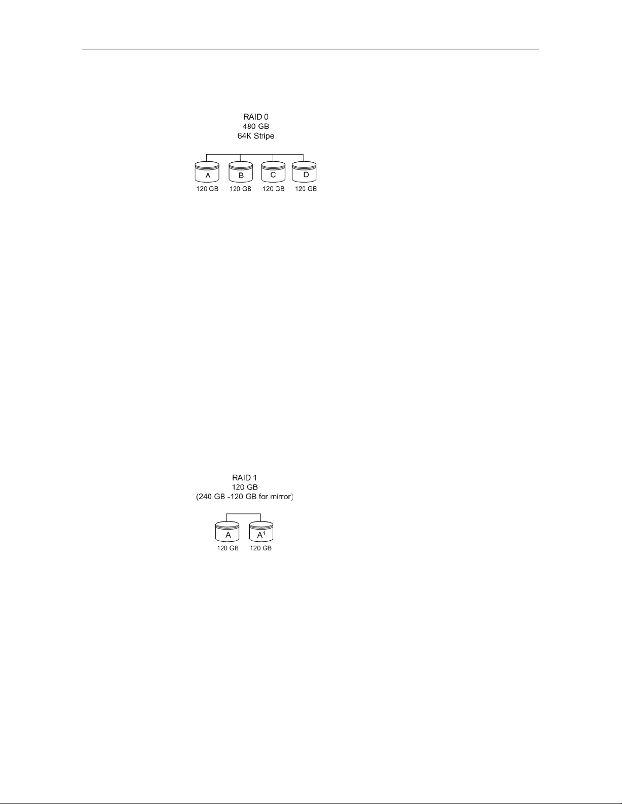
RAID 0
RAID 0 provides improved performance, but no fault tolerance. Since the
data is striped across more than one disk, RAID 0 disk arrays achieve high
transfer rates because they can read and write data on more than one drive
simultaneously. The stripe size is configurable during unit creation. RAID 0
requires a minimum of two drives.
When drives are configured in a striped disk array (see Figure 2), large files
are distributed across the multiple disks using RAID 0 techniques.
Striped disk arrays give exceptional performance, particularly for data
intensive applications such as video editing, computer-aided design and
geographical information systems.
RAID 0 arrays are not fault tolerant. The loss of any drive results in the loss of
all the data in that array, and can even cause a system hang, depending on
your operating system. RAID 0 arrays are not recommended for high
availability systems unless additional precautions are taken to prevent system
hangs and data loss.
www.3ware.com 5
Page 16
Chapter 1. Introducing the 3ware® SATA RAID Controller
Figure 2. RAID 0 Configuration Example
RAID 1
RAID 1 provides fault tolerance and a speed advantage over non-RAID disks.
RAID 1 is also known as a mirrored array. Mirroring is done on pairs of
drives. Mirrored disk arrays write the same data to two different drives using
RAID 1 algorithms (see Figure 3). This gives your system fault tolerance by
preserving the data on one drive if the other drive fails. Fault tolerance is a
basic requirement for critical systems like web and database servers.
3ware uses a patented technology, TwinStor®, on RAID 1 arrays for
improved performance during sequential read operations. With TwinStor
technology, read performance is twice the speed of a single drive during
sequential read operation.
The adaptive algorithms in TwinStor technology boost performance by
distinguishing between random and sequential read requests. For the
sequential requests generated when accessing large files, both drives are used,
with the heads simultaneously reading alternating sections of the file. For the
smaller random transactions, the data is read from a single optimal drive head.
Figure 3. RAID 1 Configuration Example
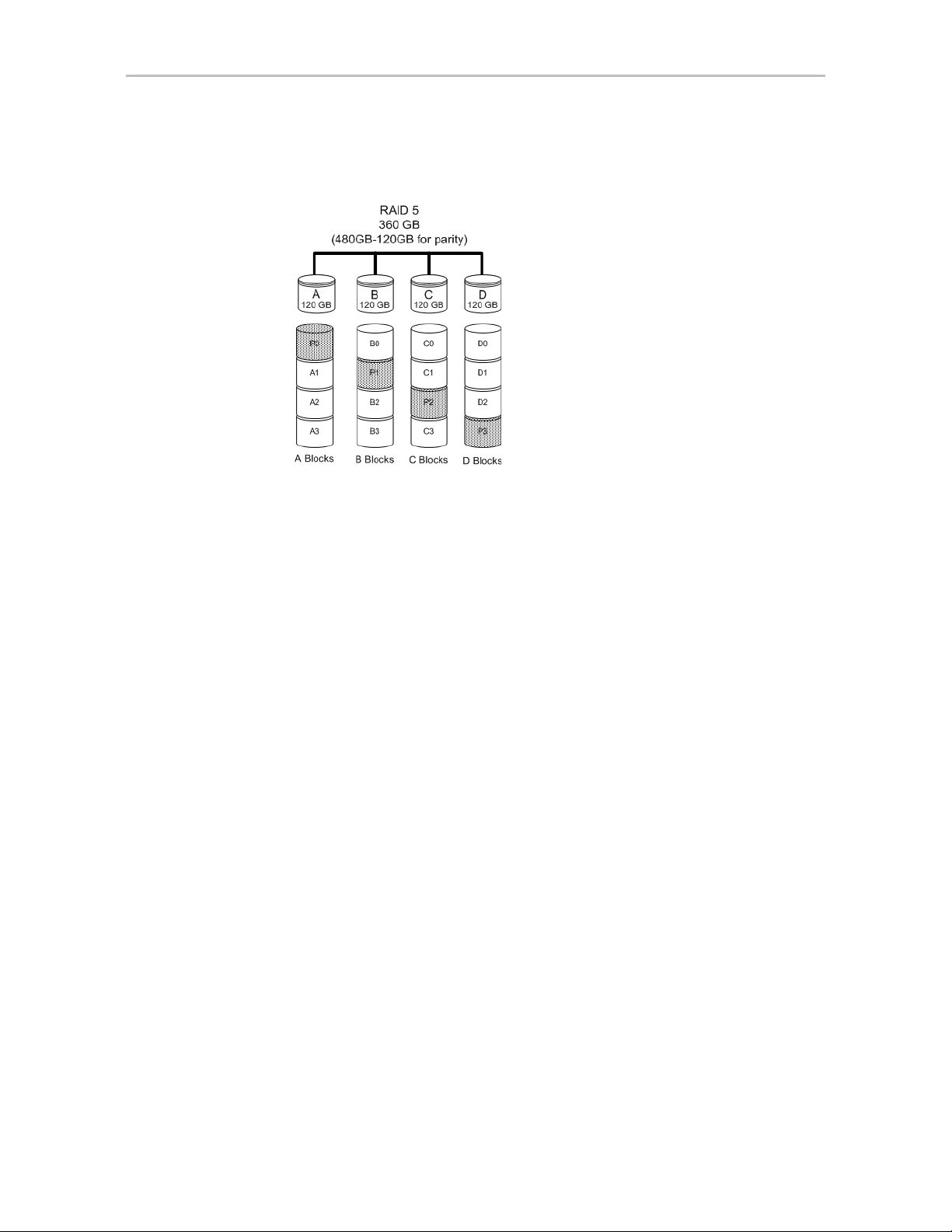
RAID 5
RAID 5 provides performance, fault tolerance, high capacity, and storage
efficiency. It requires a minimum of three drives and combines striping data
with parity (exclusive OR) to restore data in case of a drive failure.
Performance and efficiency increase as the number of drives in a unit
increases.
Parity information is distributed across all of the drives in a unit rather than
being concentrated on a single disk (see Figure 4). This avoids throughput
loss due to contention for the parity drive.
6 3ware Serial ATA RAID Controller User Guide
Page 17
Understanding RAID Concepts and Levels
RAID 5 is able to tolerate 1 drive failure in the unit.
Figure 4. RAID 5 Configuration Example
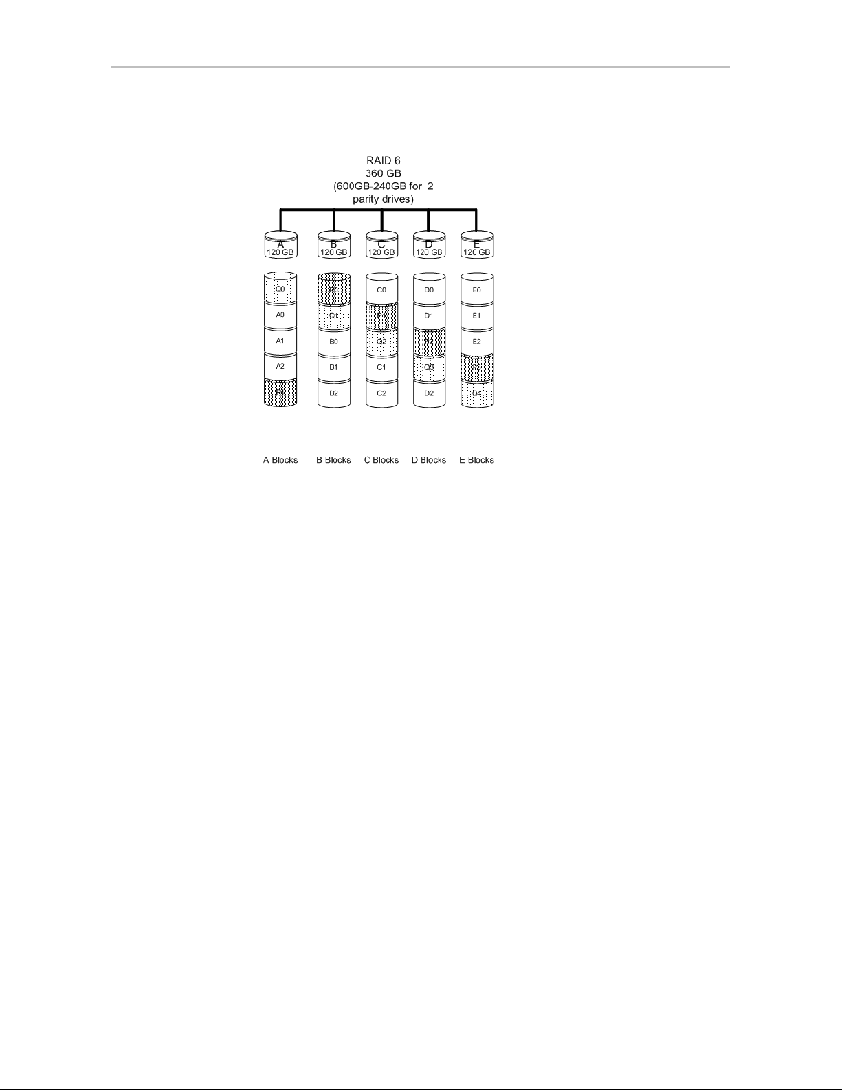
RAID 6
RAID 6 requires a 3ware 9650SE RAID controller.
RAID 6 provides greater redundancy and fault tolerance than RAID 5. It is
similar to RAID 5, but has two blocks of parity information (P+Q) distributed
across all the drives of a unit, instead of the single block of RAID 5.
Due to the two parities, a RAID 6 unit can tolerate two hard drives failing
simultaneously. This also means that a RAID 6 unit may be in two different
states at the same time. For example, one sub-unit can be degraded, while
another may be rebuilding, or one sub-unit may be initializing, while another
is verifying.
RAID 6 requires a minimum of five drives. Performance and storage
efficiency also increase as the number of drives increase.
www.3ware.com 7
Page 18
Chapter 1. Introducing the 3ware® SATA RAID Controller
Figure 5. RAID 6 Configuration Example
RAID 10
RAID 10 is a combination of striped and mirrored arrays for fault tolerance
and high performance.
When drives are configured as a striped mirrored array, the disks are
configured using both RAID 0 and RAID 1 techniques, thus the name RAID
10 (see Figure 6). A minimum of four drives are required to use this
technique. The first two drives are mirrored as a fault tolerant array using
RAID 1. The third and fourth drives are mirrored as a second fault tolerant
array using RAID 1. The two mirrored arrays are then grouped as a striped
RAID 0 array using a two tier structure. Higher data transfer rates are
achieved by leveraging TwinStor and striping the arrays.
In addition, RAID 10 arrays offer a higher degree of fault tolerance than
RAID 1 and RAID 5, since the array can sustain multiple drive failures
without data loss. For example, in a twelve-drive RAID 10 array, up to six
drives can fail (half of each mirrored pair) and the array will continue to
function. Please note that if both halves of a mirrored pair in the RAID 10
array fail, then all of the data will be lost.
8 3ware Serial ATA RAID Controller User Guide
Page 19

Understanding RAID Concepts and Levels
Figure 6. RAID 10 Configuration Example
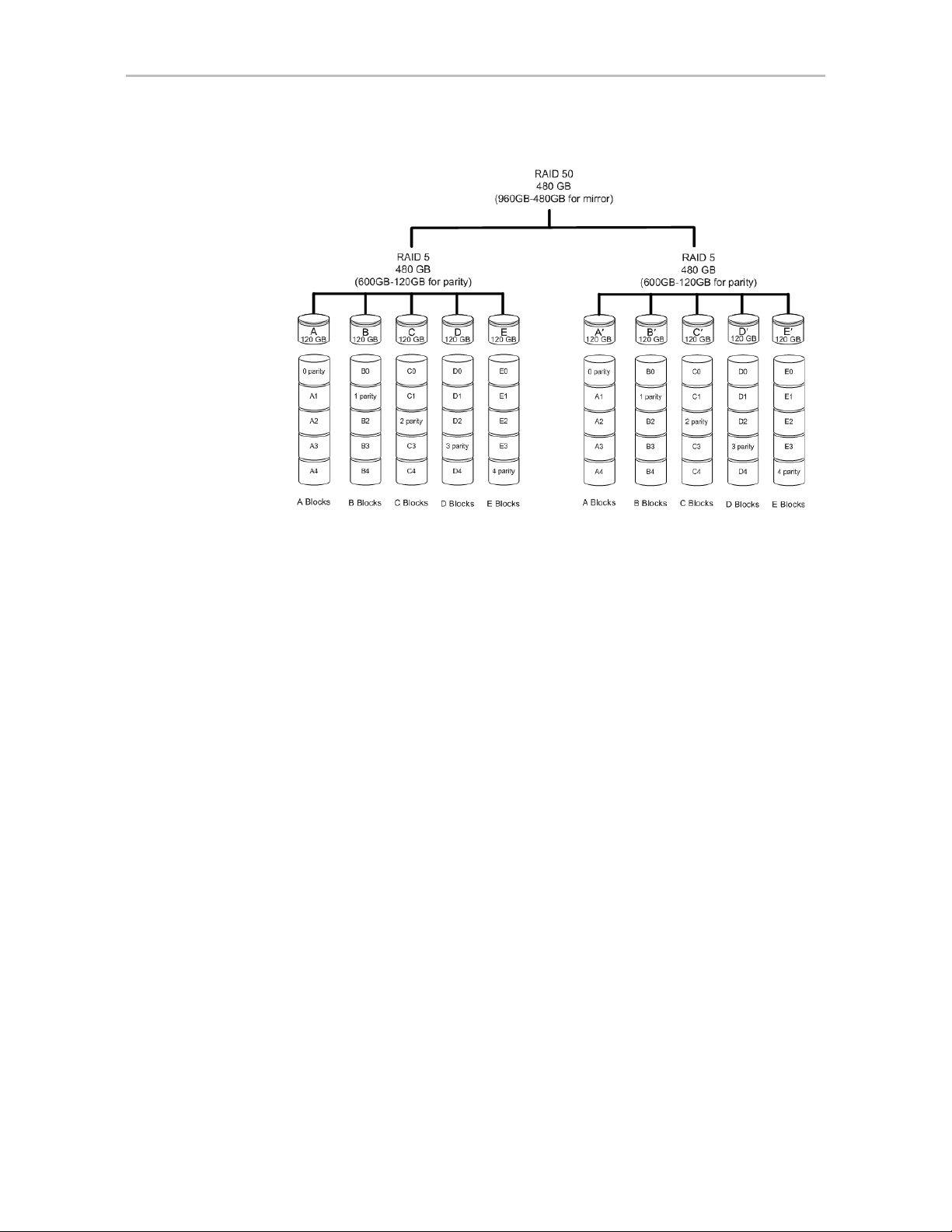
RAID 50
RAID 50 is a combination of RAID 5 with RAID 0. This array type provides
fault tolerance and high performance. RAID 50 requires a minimum of six
drives.
Several combinations are available with RAID 50. For example, on a 12-port
controller, you can hav e a grouping of 3, 4, or 6 drives. A grouping of 3 means
that the RAID 5 arrays used have 3 disks each; four of these 3-drive RAID 5
arrays are striped together to form the 12-drive RAID 50 array. On a 16-port
controller, you can have a grouping of 4 or 8 drives.
In addition, RAID 50 arrays offer a higher degree of fault tolerance than
RAID 1 and RAID 5, since the array can sustain multiple drive failures
without data loss. For example, in a twelve-drive RAID 50 array, up to one
drive in each RAID 5 set can fail and the array will continue to function.
Please note that if two or more drives in a RAID 5 set fail, then all of the data
will be lost.
www.3ware.com 9
Page 20
Chapter 1. Introducing the 3ware® SATA RAID Controller
Figure 7. RAID 50 Configuration Example
Single Disk
A single drive can be configured as a unit through 3ware software. (3BM,
3DM 2, or CLI). Like disks in other RAID configurations, single disks
contain 3ware Disk Control Block (DCB) information and are seen by the OS
as available units.
Single drives are not fault tolerant and therefore not recommended for high
availability systems unless additional precautions are taken to prevent system
hangs and data loss.
JBOD
A JBOD (acronym for “Just a Bunch of Disks”) is an unconfigured disk
attached to your 3ware RAID controller. JBOD configuration is no longer
supported in the 3ware 9000 series. AMCC recommends that you use Single
Disk as a replacement for JBOD, to take advantage of advanced features such
as caching, OCE, and RLM.
JBOD units are not fault tolerant and therefore not recommended for high
availability systems unless additional precautions are taken to prevent system
hangs and data loss.
Hot Spare
A hot spare is a single drive, available online, so that a redundant unit can be
automatically rebuilt in case of drive failure.
10 3ware Serial ATA RAID Controller User Guide
Page 21
Understanding RAID Concepts and Levels
Determining What RAID Level to Use
Your choice of which type of RAID unit (array) to create will depend on your
needs. You may wish to maximize speed of access, total amount of storage, or
redundant protection of data. Each type of RAID unit offers a different blend
of these characteristics.
The following table provides a brief summary of RAID type characteristics.
Table 3: RAID Configuration Types
RAID Type Description
RAID 0 Provides performance, but no fault tolerance.
RAID 1 Provides fault tolerance and a read speed advantage over non-
RAID disks.
RAID 5 This type of unit provides performance, fault tolerance, and high
storage efficiency. RAID 5 units can tolerate one drive failing
before losing data.
RAID 6 Provides very high fault tolerance with the ability to protect
against two consecutive drive failures. Performance and
efficiency increase with higher numbers of drives.
RAID 10 A combination of striped and mirrored units for fault tolerance
and high performance.
RAID 50 A combination of RAID 5 and RAID 0. It provides high fault
tolerance and performance.
Single Disk Not a RAID type, but supported as a configuration.
Provides for maximum disk capacity with no redundancy.
You can create one or more units, depending on the number of drives you
have installed.
Table 4: Possible Configurations Based on Number of Drives
# Drives Possible RAID Configurations
1 Single disk or hot spare
2 RAID 0 or RAID 1
3RAID 0
RAID 1 with hot spare
RAID 5
4 RAID 5 with hot spare
RAID 10
Combination of RAID 0, RAID 1, single disk
www.3ware.com 11
Page 22
Chapter 1. Introducing the 3ware® SATA RAID Controller
Table 4: Possible Configurations Based on Number of Drives
# Drives Possible RAID Configurations
5RAID 6
RAID 5 with hot spare
RAID 10 with hot spare
Combination of RAID 0, RAID 1, hot spare, single disk
6 or more RAID 6
RAID 6 with hot spare
RAID 50
Combination of RAID 0, 1, 5, 6,10, hot spare, single disk
Using Drive Capacity Efficiently
To make the most efficient use of drive capacity, it is advisable to use drives
of the same capacity in a unit. This is because the capacity of each drive is
limited to the capacity of the smallest drive in the unit.
The total unit capacity is defined as follows:
Table 5: Drive Capacity
RAID Level Capacity
Single Disk Capacity of the drive
RAID 0 (number of drives) X (capacity of the smallest drive)
RAID 1 Capacity of the smallest drive
RAID 5 (number of drives - 1) X (capacity of the smallest drive)
Storage efficiency increases with the number of disks:
storage efficiency = (number of drives -1)/(number of drives)
RAID 6 (number of drives - 2) x (capacity of the smallest drive)
RAID 10 (number of drives / 2) X (capacity of smallest drive)
RAID 50 (number of drives - number of groups of drives) X (capacity of the
smallest drive)
Through drive coercion, the capacity used for each drive is rounded down so
that drives from differing manufacturers are more likely to be able to be used
as spares for each other. The capacity used for each drive is rounded down to
the nearest GB for drives under 45 GB (45,000,000,000 bytes), and rounded
down to the nearest 5 GB for drives over 45 GB. For example, a 44.3 GB
drive will be rounded down to 44 GB, and a 123 GB drive will be rounded
down to 120 GB. For more information, see the discussion of drive coercion
under “Creating a Hot Spare” on page 103.
12 3ware Serial ATA RAID Controller User Guide
Page 23

3ware Tools for Configuration and Management
Support for Over 2 Terabytes
Windows 2000, Windows XP (32-bit), Linux 2.4, and FreeBSD 4.x, do not
currently recognize unit capacity in excess of 2 TB.
If the combined capacity of the drives to be connected to a unit exceeds 2
Terabytes (TB), you can enable auto-carving when you configure your units.
Auto-carving divides the available unit capacity into multiple chunks of 2 TB
or smaller that can be addressed by the operating systems as separate
volumes. The carve size is adjustable from 1024 MB to 2048 MB (default)
prior to unit creation.
If a unit over 2 TB was created prior to enabling the auto-carve option, its
capacity visible to the operating system will still be 2TB; no additional
capacity will be registered. To change this, the unit has to be recreated.
For more information, see “Using Auto-Carving for Multi LUN Support” on
page 86.
3ware Tools for Configuration and
Management
3ware software tools let you easily configure the drives attached to your
3ware RAID controller, specifying which drives should be used together as a
RAID unit and the type of RAID configuration you want, and designating hot
spares for use if a drive degrades.
3ware provides the following tools for use in configuring and managing units
attached to the 3ware controller:
• 3BM (3ware BIOS Manager)
3BM is a BIOS level tool for creating, deleting, and maintaining disk
arrays, rebuilding arrays, designating hot spares, and setting controller
policies. 3BM is the tool most frequently used to configure units
immediately after installation of the controller, but can also be used after
installation to maintain the controller and associated drives.
For general information about working with 3BM, seeChapter 5, “3ware
BIOS Manager 2 (3BM 2) Introduction.”
• 3DM 2 (3ware Disk Manager)
3DM is a daemon (under Linux and FreeBSD) and a service (under
Windows) which runs in the background on the controller’s host system,
and can be accessed through a web browser to provide ongoing
monitoring and administration of the controller and associated drives. It
can be used locally (on the system that contains the 9000) or remotely (on
a system connected via a network to the system containing the 9000).
www.3ware.com 13
Page 24

Chapter 1. Introducing the 3ware® SATA RAID Controller
For details about working with 3DM, see “3DM 2 (3ware Disk Manager)
Introduction” on page 66.
3DM 2 is the current version of the 3ware Disk Manager . Th roughout this
documentation, it is referred to interchangeably as 3DM and 3DM 2.
• 3ware Alert Utility (WinAVAlarm)
The 3ware Alert Utility for Windows runs on the system in which the
3ware RAID controller is installed and provides direct notification by
popup message and audio alarm when events occur. This utility can be
configured to specify the type of events that should generate these
notifications. For details, see “Using the Alert Utility Under W indows” on
page 139.
• 3ware CLI (Command Line Interface)
The 3ware CLI provides the functionality available in 3DM through a
Command Line Interface. You can view unit status and version
information and perform maintenance functions such as adding or
removing drives, and reconfiguring RAID units online. You can also use
it to remotely administer controllers in a system.
The 3ware CLI is described in 3ware Serial ATA RAID Controller CLI
Guide and in the 3ware HTML Bookshelf.
Monitoring, Maintenance, and Troubleshooting Feat ures
Several 3ware RAID controller features aid in monitoring and
troubleshooting your drives.
•
SMART Monitoring (Self-Monitoring, Analysis and Reporting
Technology) automatically checks a disk drive's health every 24 hours
and reports potential problems. This allows you to take proactive steps to
prevent impending disk crashes. SMART data is checked on all disk
drives (array members, single disks, and hot spares). Monitoring of
SMART thresholds can be turned on and off in 3DM. (For details, see
“V iewin g SMART Data About a Drive” on page 141.)
Staggered Spinup allows drives that support this feature to be powered-
•
up into the standby power management state to minimize in-rush current
at power-up and to allow the controller to sequence the spin-up of drives.
Both SAT AII OOB and ATA spin-up methods are supported. The standby
power management state is persistent after power-down and power-up.
You can set the number of drives that will spin up at the same time, and
the time between staggers in 3BM (the 3ware BIOS Management utility).
For details, see “Enabling and Setting Up Staggered Spin-up” on page 89.
•
Verification and Media Scans. The verify task verifies all redundant
units, and checks for media errors on single disks, spares, JBODS and
14 3ware Serial ATA RAID Controller User Guide
Page 25

Monitoring, Maintenance, and Troub leshooting Features
RAID 0 unit members. If the disk drive is part of a redundant unit, error
locations that are found and are deemed repairable are rewritten with the
redundant data. This forces the drive firmware to reallocate the error
sectors accordingly. (For more information, see “About Verification” on
page 146.)
Error Correction. Bad sectors can be dynamically repaired through error
•
correction (Dynamic Sector Repair). Reallocation of blocks is based
intelligently on the location of the block in relation to the stripe.
Scheduled Background Tasks. Initialize, rebuild, verify, and self-test
•
tasks can all be run in the background, at scheduled times. This lets you
choose a time for these tasks to be run when it will be least disruptive to
your system. You can also define the rate at which background tasks are
performed, specifying whether I/O tasks should be given more processing
time, or background rebuild and verify tasks should be given more
processing time. (For more information, see “Scheduling Background
Tasks” on page 156.)
Write Cache. Write cache can be enabled or disabled using 3BM 2,
•
3DM 2 and CLI. When write cache is enabled, data will be stored in
system cache, 3ware controller cache, and drive cache before the data is
committed to disk. This allows the system to process multiple write
commands at the same time, thus improving performance. However when
data is stored in cache, it could be lost if a power failure occurs. With a
Battery Backup Unit (BBU) installed, the cache stored on the 3ware
controller can be restored. (For more information, see “Enabling and
Disabling the Unit Write Cache” on page 108.)
•
StorSave™ Profiles allow you to set the level of protection versus
performance that is desired for a unit when write cache is enabled. (For
more information, see “Setting the StorSave Profile for a Unit” on
page 112.)
•
Drive and Unit Identification. Units or drives in enclosures can be
2
identified by flashing LEDs. When the I
C port on the controller has been
connected to a chassis with a Chassis Control Unit (CCU), such as the
3ware Sidecar, you can issue drive Locate commands that blink the LEDs
for particular drives, so that you can quickly identify which drive needs to
be checked or replaced. For more information, see “Locating a Drive by
Blinking Its LED” on page 161.
Auto Rebuild. For times when you do not have a spare available, setting
•
the Auto Rebuild policy allows rebuilds to occur with an available drive
or with a failed drive. (For more information, see “Setting the Auto
Rebuild Policy” on page 85.)
www.3ware.com 15
Page 26

2
Getting Started with Your 3ware RAID Controller
Setting up your 3ware RAID controller involves these main steps:
• Physically Install the RAID Controller and Drives
• Configure a RAID Unit
• Install the Driver and Make the Operating System Aware of the New
Drives
• Set Up Management and Maintenance Features
Once the controller and drives have been physically installed, the order in
which you perform these steps depends in part on whether one of the units
you configure will act as your boot drive.
Tip: When you are first setting up your system, you may want to review
“System Requirements” on page 2.
Physically Install the RAID Controller and Drives
To install your controller, follow the instructions in the installation guide that
came with your 3ware controller. If you do not have a hardcopy of the
installation manual, it is available in the “doc” folder on your 3ware CD, or
you can download it from the 3ware website at http://www.3ware.com/
support/userdocs.asp.
For drive installation, see the instructions that came with your 3ware Sidecar
or other external enclosure. If you are installing drives in a computer case,
follow the manufacturer’s instructions.
Configure a RAID Unit
If you would like more information about what RAID level to choose for your
situation, review the information under “Understanding RAID Concepts and
Levels” on page 4. Then turn to “Configuring a New Unit” on page 91.
If you want to install the operating system on and boot from a drive managed
through the new 3ware RAID controller, use the 3ware BIOS Manager (3BM)
to define the configuration. You will find step-by-step instructions for initial
16 3ware Serial ATA RAID Controller User Guide
Page 27

installation in. Chapter 3, “First-Time RAID Configuration Using 3BM.”
Additional information about configuration is also included in the later
chapters of this user guide.
If the operating system is already installed on another drive in your system,
you can configure units through 3BM, through 3ware Disk Manager (3DM),
or through the Command Line Interface (CLI). If you want to use 3DM or the
CLI for configuration, go ahead and boot to the operating system, install the
driver and the 3DM 2 software, and then configure your units. You may want
to refer to the following information:
• Chapter 6, “3DM 2 (3ware Disk Manager) Introduction”
• Chapter 8, “Configuring Units”
• 3ware Serial ATA RAID Controller CLI Guide, available from the CD-
ROM, the 3ware HTML Bookshelf and from the website http://
www.3ware.com/support/userdocs.asp
Install the Driver and Make the Operating System Aware of the New Drives
Instructions for installing drivers are available in “Driver Installation” on
page 30.
You will also find instructions for updating the driver under “Downloading
the Driver and Firmware” on page 165.
Set Up Management and Maintenance Features
3ware RAID controllers include a number of features to help you manage and
maintain the controller and your configured units. The default settings for
these features allow you to begin using your newly configured units right
away. You can review and change these features as a final step in your initial
setup, or you can make changes to them later, at your convenience. These
features include:
• Controller and unit policies, such as Auto Rebuild, Auto Verify, use of
write cache, use of queuing mode, selection of a StorSave profile, and
specifying how unconfigured disks (JBODs) are handled.
• Email notification of alarms and other events
• Schedules for when background tasks will be performed, to minimize the
impact on day-to-day performance during peak usage times. (Background
tasks include rebuild, verify, initialize, migrate, and self-test.)
Details about these features are described in this documentation. When you
first set up your controller, you may want to review these sections in
particular:
www.3ware.com 17
Page 28
Chapter 2. Getting Started with Your 3ware RAID Controller
• “Configuring Your Controller” on page 80
• “Setting Unit Policies” on page 106
• “Setting Background Task Rate” on page 155
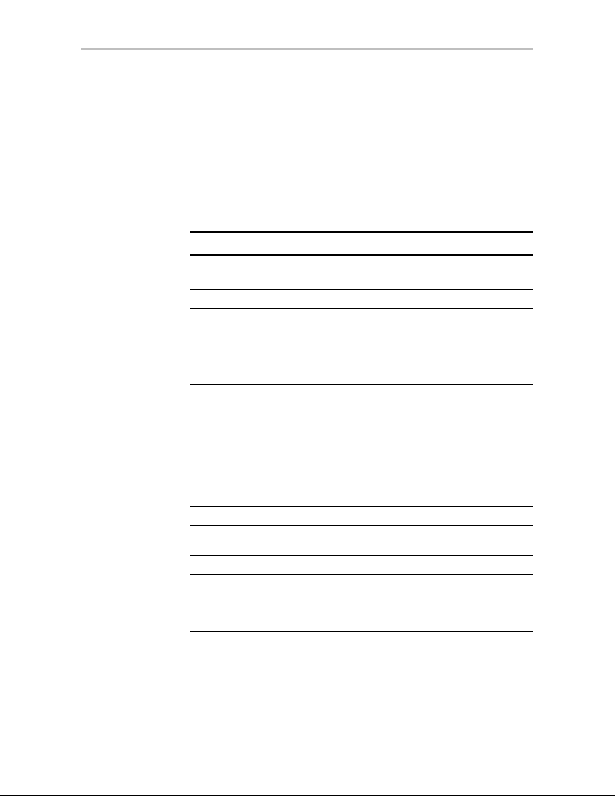
Initial Settings for Policies and Background Tasks
The table below lists the default settings for policies and background tasks.
These settings are used if you do not explicitly change the policy settings.
Table 6: Default Settings for Policies and Background Tasks
Policy Default Value Where to Change
Controller-Level Settings
(For details, see “Configuring Your Controller” on page 80
Auto-Rebuild Enabled 3BM, 3DM, CLI
Auto-Carving Disabled 3BM, 3DM, CLI
Auto-Detect Enabled CLI
Carve Size or Factor 2048 GB 3BM, 3DM, CLI
Drives Per Spinup 1 3BM, CLI
Delay Between Spinup 6 seconds 3BM, CLI
Export Unconfigured (JBOD)
Disks
Staggered Method ATA-6 3BM
Staggered Spinup Enabled 3BM
Unit-Level Settings
(For details, see “Setting Unit Policies” on page 106)
Auto Verify Disabled 3DM, CLI
Continue on Source Error
During Rebuild
Boot Volume Size Blank 3BM
Queuing (NCQ) Enabled 3BM, 3DM, CLI
StorSave Profile Protection 3BM, 3DM, CLI
Write Cache Enabled 3BM, 3DM, CLI
Disabled 3BM, CLI
Disabled 3BM, 3DM, CLI
Background Task Settings
(For details, see “Scheduling Background Tasks” on page 156 and “Setting
Background Task Rate” on page 155)
18 3ware Serial ATA RAID Controller User Guide
Page 29

Table 6: Default Settings for Policies and Background Tasks
Policy Default Value Where to Change
Verify Task Schedules
starting at 12:00 am
Daily,
3DM, CLI
and running for 24 hours
Follow Verify Task Schedule No 3DM, CLI
Rebuild Task Schedules
Daily,
starting at 12:00 am
3DM, CLI
and running for 24 hours
Follow Rebuild T ask
Schedule
Self-test Task Schedules
a
No 3DM, CLI
Daily, starting at 12:00 am
3DM, CLI
and running for 24 hours
Follow Self-test Task
Schedule
Yes 3DM, CLI
a. Although the default Self-test Task Schedule is for 24 hours, self-test
tasks are run only at the beginning of that time period and take just a few
minutes. For more information about task schedules, see “Scheduling
Background Tasks” on page 156.
www.3ware.com 19
Page 30
3
First-Time RAID Configuration Using 3BM
If you will install the operating system on and boot from a unit managed
through the new 3ware RAID controller, follow the steps in this chapter to use
the 3ware BIOS Manager (3BM) to configure the unit and install the driver.
If the operating system is already installed on another drive in your system,
you can use the steps below or you can configure units through 3DM or the
CLI.
You can create one or more units on a single controller, depending on the
number of drives that the specific 3ware RAID controller supports and the
number of drives attached. (For more information, see “Determining What
RAID Level to Use” on page 11.)
Basic Steps for Creating a Unit
The process of configuring your RAID units includes these main steps, which
are detailed in the step-by-step example:
• Launch 3BM (3ware BIOS Manager)
• Select the drives to be included and indicate that you want to create a unit
• Select the desired RAID configuration
• Set other parameters, depending on the type of RAID configuration
• Confirm the unit configuration
• Save your changes and finish up
Note: If the capacity of the unit you create will exceed 2TB and you are using
Windows 2000, Windows XP (32-bit), Linux 2.4, or FreeBSD 4.x, you will need to
enable auto-carving. Before creating your unit, follow the instructions under “Using
Auto-Carving for Multi LUN Support” on page 86.
20 3ware Serial ATA RAID Controller User Guide
Page 31

Basic Steps fo r Creating a Unit
To launch 3BM
1 Power up or reboot your system.
While the system is starting, watch for a screen similar to Figure 8.
Figure 8. 3ware BIOS Screen
----Press <Alt-3> to access 3ware BIOS Manager ---3ware ATA RAID Controller: 9590SE-12
BIOS: BE9X X.XX.XX.XXX Firmware: FE9X X.XX.XX.XXX
BBU Status: Not Present
Number of online units: 1, available drives: 0, hot spare: 0, offline units:0
Exportable Units:Œ
3drive 64K RAID5 558.77GB (PrimaryRAID5)
SATA - Maxtor 7B300S0 279.48 GB (Port 5)
SATA - Maxtor 7B300S0 279.48 GB (Port 6)
SATA - Maxtor 7B300S0 279.48 GB (Port 7)
2 Press Alt-3 immediately to bring up the 3ware BIOS Manager (3BM).
Normally your 3ware configuration remains on-screen for just a few
seconds. However, if a unit has degraded, the screen indicates the
problem and remains on your screen longer.
3 If you have more than one 9000-series controller in your system, a screen
lists the available boards. (See Figure 9.) In this case, highlight the board
with which you want to work and press Enter.
Figure 9. 3ware Controller Board Selection Screen
You see a screen similar to Figure 10, warning you that changing your
disk array configuration may overwrite data on the disks.
www.3ware.com 21
Page 32

Chapter 3. First-Time RAID Configuration Using 3BM
4 If you plan to make changes to your config uration and need to backup
data before continuing, press ESC and do so now. Otherwise, press any
key to continue.
Figure 10. Warning Message When you Start 3BM
To select the drives and create a unit
1 Select the drives to be included by highlighting each one and pressing
Enter to select it.
When you select a drive, an asterisk appears next to it in the left-most
column (see Figure 11).
You may include from one to twenty-four drives in the unit, depending on
the number available.
Figure 11. Asterisks Next to Selected Drives
2 After all drives for the unit are selected, use the Tab to move to the
Create Unit button and press Enter.
The Create Disk Array screen appears (see Figure 12).
22 3ware Serial ATA RAID Controller User Guide
Page 33

Basic Steps fo r Creating a Unit
3 Make sure that the proper drives are listed.
Figure 12. Create Disk Array Display, RAID 0 Example
To name the unit and select the desired RAID configuration
1 (Optional) Press Enter in the Array Name field and type a name for the
unit. Then press Enter again to accept the name.
2 Use the arrow keys or press Tab to move to the RAID Configuration
field and press Enter to display the available RAID levels for the number
of drives you selected.
Figure 13. List of Configuration Choices for Four Drives
3 Use the arrow keys to highlight the desired RAID configuration and
press Enter.
For information about the different RAID levels and when to use each,
see “Understanding RAID Concepts and Levels” on page 4.
4 Use the arrow keys or press Tab to move to the field Stripe Size and
select the desired stripe size (16KB, 64KB, or 256KB).
Notes:
Striping size is not applicable for RAID 1, because it is a mirrored unit
without striping.
For RAID 6, only stripe size of 64KB is supported.
In general, use smaller stripe sizes for sequential access (such as video
access) and larger stripe sizes for random access (such as a database).
www.3ware.com 23
Page 34

Chapter 3. First-Time RAID Configuration Using 3BM
Figure 14. Stripe Sizes for a RAID 5
To set other policies for the unit
While creating a unit through 3BM, you can set several policies that effect the
unit (Write Cache, Drive Queuing Mode, and Continue on Error When
Rebuild), and you can select a StorSave profile.
Each of these policies is already set to a default value, so you do not have to
change them. In addition, you can change each of these policies later without
affecting the configuration.
1 Use the arrow keys or press Tab to move to the field you want to change.
2 Press Enter to see the available options.
3 Use the arrow keys to select the option you want and press Enter to
choose it.
For details about these parameters, see:
• “Enabling and Disabling the Unit Write Cache” on page 108
• “Enabling and Disabling Queuing for a Unit” on page 111
• “Setting the StorSave Profile for a Unit” on page 112
• “Setting Continue on Source Error During Rebuild” on page 110
To create a boot unit of a particular size
You can specify a portion of the unit you create to be used as a boot volume, if
desired. This is useful if you will be installing your operating system onto the
unit and want to have a designated volume for the OS. The remainder of the
unit will be created as a separate volume.
24 3ware Serial ATA RAID Controller User Guide
Page 35

Basic Steps fo r Creating a Unit
Note: Setting a Boot Volume Size is optional. In addition, if you specify a boot
volume, you do not have to install your operating system onto it. For more
information about creating a boot volume, see “Boot volume size” on page 94. If the
size your array is 2TB or greater, you may also want to review the information about
carving the unit into multiple volumes. For details, see “Using Auto-Carving for Multi
LUN Support” on page 86.
1 Use the arrow keys or press Tab to move to the Boot Volume Size field.
2 Press Enter to display a text box.
3 Enter the size in Gigabytes that should be assigned to the boot volume.
4 Press Enter again to accept the size.
To confirm unit configuration
1 Press Tab to select the OK button and press Enter to confirm creation of
the unit.
Or, if you want to cancel the creation of the unit, tab to Cancel and press
Enter.
2 If you leave the Unit Write Cache field enabled and do not have a BBU
installed, 3BM will ask you to confirm that you want enable write cache.
The unit is not actually created and no data is overwritten until you have
finished making all your changes and press F8.
3 If the volume summary screen appears, review the information and press
any key to continue.
Multiple volumes will be created if you entered a Boot Volume Size of
greater than zero (0), or if auto-carving is enabled and the combined size
of the drives in your unit is large enough to divide it into multiple
volumes. For more information about auto-carving, see “Using AutoCarving for Multi LUN Support” on page 86.
www.3ware.com 25
Page 36

Chapter 3. First-Time RAID Configuration Using 3BM
Figure 15. Summary of Volumes to be Created
To finish up and save your changes
1 If you have additional drives, you can go ahead and configure an
additional RAID unit or designate a hot spare. Then continue on with
these steps. (For details about hot spares, see page 28.)
2 If you configured more than one unit, and you plan to install the operating
system on one of them, make that unit be the first unit (Unit 0) in the list
of Exportable Units.
To move a unit up in the list, highlight it and press the Page Up key.
You will also want to make sure that the controller is the boot device for
your computer . After finalizing the configuration below, be sure to follow
the steps under “Checking the Motherboard Boot Sequence” on page 29.
3 When you are finished configuring units, press F8 to save the changes
and exit 3BM.
A warning message asks you to confirm that all existing data on the drives
will be deleted.
Figure 16. Confirmation Message when Saving and Exiting
26 3ware Serial ATA RAID Controller User Guide
Page 37

Basic Steps fo r Creating a Unit
4Type Y to continue, delete any existing data on the drives, and create the
unit.
Depending on the RAID configuration you are creating, initialization of
the unit may begin immediately. (RAID 6 units and some RAID 5 and
RAID 50 units begin immediate initialization.) The initialization process
can take several hours, depending on the size of your drives.
5 If you want to use a RAID configuration which has started initializing,
you can press Esc to cancel the progress box. (Before doing this, be sure
to read “Trade-offs to cancelling initialization,” below.)
You can then exit 3BM and boot to the operating system before the
process of writing zeroes to the drives is complete. Once you have booted
to the operating system, background initialization of the unit will begin
after a delay of up to ten minutes.
Trade-offs to cancelling initialization:
• Performance of these units will be lower until initialization is
complete.
• When initializing is done after booting to the operating system,
the process of initializing takes longer than it does if initialization
is done by writing zeroes to the unit in the BIOS. Consequently, it
will be a longer period of time until the performance of the unit is
fully optimal. Data remains intact when initialization is done in the
operating system.
For complete information about initialization of RAID units, see “About
Initialization” on page 143.
6 If you are finished creating RAID units, be sure to check the boot
sequence for your system, as described under “Checking the Motherboard
Boot Sequence” on page 29.
www.3ware.com 27
Page 38

Chapter 3. First-Time RAID Configuration Using 3BM
Specifying a Hot Spare
You can designate one of the Available Drives as a hot spare in 3BM. If a hot
spare is specified and a redundant unit degrades, an event notification will be
generated. The hot spare will automatically replace the failed drive without
user intervention.
To specify a hot spare
1 In the list of Available Drives, highlight the drive to use.
2Type s to specify that the selected drive will be the hot spare.
You’ll see the words “Hot Spare” appear next to the drive in the Available
Drives list.
Figure 17. Hot Spare Indicated
If a hot spare is already enabled, you can disable it by following the same
process.
Note: In order to replace a failed drive in a degraded unit, a hot spare drive
must have the same or larger storage capacity than the failed drive.
Leaving Individual Drives as JBODs
By default, if you leave individual drives unconfigured (JBODs), they will not
be available to the operating system. If you want to be able to use individual
drives, configure them as single-disk units.
If you have JBODs attached to an 8000 controller that you want to use with
the 9000 controller, see “Moving Units from an 8000 Controller to a 9000
Controller” on page 126.
28 3ware Serial ATA RAID Controller User Guide
Page 39

Checking the Motherboard Boot Sequence
Checking the Motherboard Boot Sequence
Using your computer’s Setup utility, ensure that it shows the appropriate boot
device.
After installing the 3ware 9000 controller in your system, go into the BIOS
for your computer system to check and change the boot order. This is
necessary because most systems automatically change the boot order when
they detect a newly installed controller and device. Refer to the
documentation for your system for information about starting the system
BIOS.
• If the OS is already installed on a unit connected to the system, be
sure that device precedes the 3ware RAID controller in the boot sequence.
If you have other disks installed on the motherboard, the 3ware RAID
controller should precede them in boot order.
• If you will install your OS on a disk or unit attached to the 3ware
RAID controller, specify the controller as the boot device. (Note that if
you configured more than one unit, the drive(s) specified as Unit 0 will be
treated as the boot disk.)
What Next?
The final steps in setting up your RAID units are to load the 3ware driver and
make the units available to your operating system. For details, turn to
Chapter 4, “Driver Installation.”
After installing the driver, in order to maintain your RAID units, you may also
want to install 3ware’s browser-based Disk Management tool, 3DM 2, or the
3ware Command Line Interface (CLI). For more information, see
Appendix B, “Software Installation” on page 271.
www.3ware.com 29
Page 40

4
Driver Installation
This chapter provides details about how to install the driver for your 3ware
RAID controller and make the units available to your operating system.
This section is for PCs only, for Mac OS X, see 3ware Serial ATA RAID
Controller User Guide for Mac OS X.
• If the unit you have created will be your system's boot device, you install
the driver for the controller as you install the operating system.
• If the operating system is already installed on a unit connected to another
controller or to the motherboard, you start the operating system and then
install the driver.
Details for both situations are described in this chapter. Driver information is
organized by operating system:
• “Driver Installation Under Windows” on page 31
• “Driver Installation Under Linux” on page 39
• “Driver Installation Under FreeBSD” on page 50
Note: If you are working with a system that already has a 3ware RAID controller
installed, and want to update the driver or firmware for your 3ware RAID controller
to a newer version, see the information in “Updating the Driver and Firmware” on
page 181.
30 3ware Serial ATA RAID Controller User Guide
Page 41

Driver Installation Under Windows
Driver Installation Under Windows
Note: Before installing the 3ware driver, you must have already physically installed
your 3ware RAID controller in the system.
Consult the installation guide that came with your controller for how to do this. You
can download that guide from: http://www.3ware.com/support/userdocs.asp.
The 3ware RAID controller can be used with Microsoft Windows 2000 (SP3
or newer), Windows XP (SP1 or newer), an d Win dows Server 2003. W indows
2003 64-bit for AMD Opteron or Intel EM64T is also supported. It is
recommended that you upgrade to the latest service pack available.
A drive or unit managed by the 3ware RAID controller may be configured to
be your system’s boot device. Or, you can use units managed by the 3ware
controller for secondary storage and boot from another device, such as a disk
attached to the motherboard, or other bootable media.
This section contains instructions for how to:
• Create a driver diskette for the 3ware RAID controller
• Install the 3ware driver and Windows on a new drive or unit.
• Install the 3ware driver when Windows is already installed on a different
device.
Note: You must have administrator privileges for your system to install the
Windows operating system and the 3ware driver.
Materials Required
• 3ware software CD-ROM
• Microsoft Windows 2000, XP, or Server 2003 installation CD-ROM. (No t
required if Windows is already installed on another drive.).
• Floppy diskette, to create a driver diskette.
If you are installing Windows onto the RAID unit you are creating, you
must create a 3ware driver diskette. If Windows is already installed on
another device, you may install the 3ware driver from either the 3ware
software CD-ROM or from a diskette.
www.3ware.com 31
Page 42

Chapter 4. Driver Installation
Creating a 3ware Driver Diskette
If you are installing Windows on a new unit or drive managed by the 3ware
RAID controller, you must create a 3ware driver diskette.
To create a driver diskette
1 Insert the 3ware software CD into your system.
2 When the 3ware Menu appears, click Driver and Firmware Disks.
3 In the 3ware Driver & Firmware Images menu, click the appropriate
button to create the driver diskette that you need.
Note that there are both 32-bit and 64-bit AMD drivers available for
Windows. Be sure to select the correct one.
4 When the confirm message appears, insert a blank diskette into a floppy
drive and click the Yes button to begin the process.
Installing the 3ware Driver and Windows on aNewUnit
If you want to install Windows on a new drive configuration managed by the
3ware RAID controller, follow the instructions in this section.
If Windows is already installed on another drive, turn to “Installing the Driver
on a System that Boots from a Different Device” on page 33.
To install Windows and the 3ware driver
1 Boot from the Windows 2000, Windows XP, or Windows Server 2003 CD
and press F6 when you see the message: “Press F6 if you need to install a
3rd party SCSI or RAID driver” at the bottom of the display.
2 When you see the message: “Setup could not determine the type of one or
more mass storage devices or you have chosen to manually specify an
adapter…”
Type S to specify that you have an additional 3ware RAID controller.
3 Insert the 3ware driver diskette and press Enter.
4 When a box with AMCC 3ware Series ATA RAID Controller appears,
press Enter to select it.
5Type S if you have additional devices to add. Otherwise, press Enter.
32 3ware Serial ATA RAID Controller User Guide
Page 43

Driver Installation Under Windows
6 If the “Digital Signature Not Found” message appears, click Yes to
continue the installation.
(If there are multiple controllers in the system, you will see this message
once for each controller.)
7 Continue with the normal Windows installation at this point. There are no
instructions after installing the driver that are specific to 3ware. If you
need additional instructions, refer to the Windows 2000, Windows XP, or
Windows Server 2003 documentation supplied by Microsoft.
8 Follow the instructions under “Making Units Managed by a 3ware
Controller Available to Windows” on page 38.
Installing the Driver on a System that Boots from a Different Device
If you are installing the 3ware RAID controller on a system that already has
the operating system installed on another drive, follow the instructions in this
section, depending on the version of Windows installed on your system:
• “To install the 3ware driver under Windows 2000” on page 33
• “To install the 3ware driver under Windows XP or 2003” on page 35
To install the 3ware driver under Windows 2000
When you start Windows after installing a 3ware RAID controller, Windows
recognizes it as a Plug and Play device, and brings up the Found New
Hardware Wizard. This wizard guides you through installing the 3ware
driver (see Figure 18). Note that you will see screens for the installation of
two drivers during this process.
www.3ware.com 33
Page 44

Chapter 4. Driver Installation
Figure 18. Found New Hardware Wizard, Windows 2000
1 Click the Next button and respond to the questions the Wizard displays
using the default selections.
2 When the Wizard prompts you to select a device driver, click Have Disk,
and then indicate that it is on the CD or floppy.
3 If the “Digital Signature Not Found” message appears, click Yes to
continue the installation.
4 When the Completing the Found New Hardware Wizard screen appears
(Figure 19), click Finish.
Figure 19. Completing Found New Hardware Wizard
5 If the “Completing” screen (Figure 19) indicates that you should restart
your computer, do so now.
34 3ware Serial ATA RAID Controller User Guide
Page 45

Driver Installation Under Windows
6 When the Install Hardware Device Drivers screen appears (Figure 20),
click Next and follow the prompts on the screen to install the second
driver.
Figure 20. Install Hardware Device Drivers
7 When the second Completing the Found New Hardware screen appears,
click Finish.
Figure 21. Completing Found New Hardware Wizard
After the driver has been installed, continue with the instructions under
“Making Units Managed by a 3ware Controller Available to Windows”
on page 38.
To install the 3ware driver under Windows XP or 2003
When you start Windows after installing a 3ware RAID controller, Windows
recognizes it as a Plug and Play device, and brings up the Found New
Hardware W izard. This wizard guides you in installing the 3ware driver (see
Figure 22). Note that you will see screens for the installation of two drivers
during this process.
www.3ware.com 35
Page 46

Chapter 4. Driver Installation
Figure 22. Found New Hardware Wizard, Windows XP and 2003
1 Click the Next button and respond to the questions the Wizard displays.
2 When the Wizard prompts you to select a device driver, click Have Disk,
and then indicate that it is on the CD or floppy.
3 If the “Digital Signature Not Found” message appears, click Yes to
continue the installation.
4 When the Completing the Found New Hardware Wizard screen appears
(Figure 23), click Finish.
Figure 23. Completing Found New Hardware Wizard
5 If the “Completing” screen similar to the one above indicates that you
should restart your computer, do so now.
6 When the Welcome to the Found New Hardware Wizard screen appears
again (Figure 24), click Next and follow the prompts on the screen to
install the second driver.
36 3ware Serial ATA RAID Controller User Guide
Page 47

Driver Installation Under Windows
Figure 24. Welcome to the Found New Hardware Wizard
7 When the second Completing the Found New Hardware screen appears,
click Finish.
Figure 25. Completing Found New Hardware Wizard
After the driver has been installed, continue with the instructions below under
“Making Units Managed by a 3ware Controller Available to Windows” on
page 38.
www.3ware.com 37
Page 48

Chapter 4. Driver Installation
Making Units Managed by a 3ware Controller Available to Windows
After the 3ware driver has been installed, you need to partition and format the
new units or disks.
1 Remove the driver diskette or CD, reboot the system, and log in as the
system administrator.
2Use Disk Administrator to partition and format the new units or disks:
From the Start menu, choose Administrative Tools > Computer
Management.
In the Computer Management window, under Storage, select Disk
Management.
Figure 26. Computer Management Screen
3 Follow the steps that appear on the screen to write a signature to the drive.
4 Right-click on the drive and select Create Volume.
5 Follow the steps the appear on-screen to create a volume and to assign a
drive letter.
38 3ware Serial ATA RAID Controller User Guide
Page 49

Driver Installation Under Linux
Note: Before installing the 3ware driver, you must have already installed your
3ware RAID controller in the system. Consult the installation guide that came with
your controller for how to do this. You can download that guide from: http://
www.3ware.com/support/userdocs.asp
A drive or unit managed by the 3ware RAID controller may be configured to
be your system's boot device. Or, you can use units managed by the 3ware
controller for secondary storage and boot from another device, such as a disk
attached to the motherboard, or other bootable media.
These steps assume that you do not have a 3ware 9000 Series card installed in
the system already . If you already do and you wish to ad d a 9550SX, 9590S E,
or 9650SE to that same system, you will need to upgrade the 3ware driver,
3DM 2, and/or CLI with the current version.
The steps you follow to install the driver and make your RAID unit available
depend on which version of Linux you are using, and whether it will be your
boot device. This chapter provides step-by-step inst ructions for the following:
Driver Installation Under Linux
• Red Hat / Fedora Core Linux Installation
• “Installing the 3ware Kernel Driver Module while Installing Red Hat
Linux on a New Unit” on page 42
• “Installing the 3ware Kernel Driver Module on a Red Hat or Fedora
Core Linux System that Boots From a Different Device” on page 44
• SuSE Linux Installation
• “Installing the 3ware Kernel Driver Module while Installing SuSE
Linux on a New Unit” on page 48
• “Installing the 3ware Kernel Driver Module on a SuSE Linux System
that Boots from a Different Device” on page 48
The 9.4.1 code set from the 3ware website provides compiled drivers for these
versions of Linux:
• Fedora Core 5 for AMD and Intel Platforms (32-bit & 64-bit)
• RedHat Workstation 4 (update 4) for AMD and Intel Platforms (32-bit &
64-bit)
• SuSE 10.1 Pro for AMD and Intel Platforms (32-bit & 64-bit)
• SuSE Linux Enterprise Server 10.0 for AMD and Intel Platforms (32-bit
& 64-bit)
If you are using an unsupported Linux distribution or kernel for which there is
not a driver available from the 3ware download page, see the following article
in the 3ware knowledgebase:
http://www.3ware.com/kb/article.aspx?id=14546. You can also contact
www.3ware.com 39
Page 50

Chapter 4. Driver Installation
3ware Technical Support, or email your driver request to
support1@amcc.com.
For information about how to compile a driver from the 3ware driver source,
see the links appended to knowledgebase article 14546 (http://
www.3ware.com/kb/article.aspx?id=14546).
Obtaining 3ware Linux Drivers
Obtain the 3ware driver for Linux from one of these two sources:
•
3ware software CD-ROM. Compiled and tested drivers for Red Hat and
SuSE Linux are included on this CD.
3ware web site. You can download the latest compiled and tested driver
•
for supported Linux distributions from the 3ware web site at
http://www.3ware.com/support/index.asp. Included in these downloads is
the Linux driver source, which you can use to compile the latest driver for
RedHat, SuSE, and other similar distributions, running similar kernel
strings.
Be Sure to Use the Correct Drivers
The Linux 3w-9xxx drivers included on the 3ware CD are for 3ware 965 0SE,
9590SE, 9550SX, and 9500S series controllers. 3ware 7/8000 series
controllers use a Linux driver labeled 3w-xxxx. The drivers for the 9000
series controllers and the 7/8000 series controllers are not interchangeable,
but can be used together when both controller types are installed in the same
system. The examples in this chapter refer only to the 9000 series driver
(9650SE, 9590SE, 9550SX, and 9500S). For information about using the 7/
8000 driver and controller , refer to the user gu ide or installation procedur e for
the 7/8000-series controller.
Warning: Be sure to use the correct driver for your processor. It is possible to load
the wrong driver onto a system, however when you boot such systems, they will not
work.
For Red Hat and SuSE, AMCC offers the following drivers:
• x86 32-bit for Intel x86 and AMD Athlon
• x86 64-bit for AMD Opteron and Intel Xeon (EM64T)
40 3ware Serial ATA RAID Controller User Guide
Page 51

Driver Installation Under Linux
Determining the Current Version of your 3ware Driver
If you already have a 3ware controller installed, you can check the current
driver version, using either 3DM 2 or the CLI. (For details, see “Viewing
Information About a Controller” on page 80.)
You can also check it using the following method:
If you have a 2.4 kernel or earlier,
cat /proc/scsi/3w-9xxx/*
where the asterisk (*) represents SCSI host ID and 9xxx represents the
family of the controller. For example:
cat /proc/scsi/3w-9xxx/0
If you have a 2.6 kernel with sysfs, type the following command:
cat /sys/class/scsi_host/<hostid>/stats
where <hostid> is usually host0, unless other SCSI devices are available,
in which case it may be host1 or higher.
If you have a 2.6 kernel without sysfs, type the following command:
dmesg | grep 3w
type the following command:
Driver Installation Under Red Hat Linux or Fedora Core 5
Materials required
• 3ware software CD-ROM
• Floppy diskette, if you need to create a driver install diskette.
• Red Hat Linux installation DVD or CD-ROM. (Not required if Red Hat
Linux is already installed on another drive.)
Creating a Red Hat Linux Driver Diskette
If you are installing Linux on the new drive or unit managed by the 3ware
RAID controller, you must create a 3ware driver install diskette. If Linux is
already installed on another device, you may install the 3ware ke rnel driver
module from the 3ware software CD-ROM.
To create a Red Hat Linux driver install diskette
1 Insert the 3ware software CD into your system.
2 When the 3ware Escalade Menu appears, click the Driver & Firmware
Disks button.
www.3ware.com 41
Page 52

Chapter 4. Driver Installation
3 In the 3ware Driver & Firmware Disk Images menu, click the button for
4 Insert a blank diskette into a drive and click the Yes button to begin
Note: If you need to create a Linux driver diskette for a Linux distribution other that
what is available on the menu, see 3ware knowledgebase article 14546 http://
www.3ware.com/kb/article.aspx?id=14546
To get the kernel driver module
If you only need the kernel driver module, you can get it in one of two ways:
the driver disk you want to create.
A confirmation window opens.
creating the driver floppy diskette.
• Browse the 3ware CD to
/packages/drivers/linux and copy the
appropriate kernel driver modules for your distribution release.
Or
• Follow the steps above to create a driver install diskette from the menu.
Extract the kernel driver module from the modules.cgz file, using this
command:
zcat modules.cgz|cpio -idvm
Installing the 3ware Kernel Driver Module while Installing Red Hat Linux on a New Unit
Note: If Red Hat Linux is already installed and bootable on another drive, turn to
“Installing the 3ware Kernel Driver Module on a Red Hat or Fedora Core Linux
System that Boots From a Different Device” on page 44.
Note: We have tested some older systems where a drive connected to the
motherboard interfered with using a drive or unit managed by the 3ware RAID
controller as a boot device. Disconnecting the drive while installing Linux will
eliminate this problem. After Linux is installed, the drive can be reconnected.
To install the 3ware kernel driver module while installing Red Hat
or Fedora Core Linux on a new unit
1 Boot with the Red Hat or Fedora Core DVD or CD:
a Insert the Red Hat DVD or CD-ROM disk into your computer.
b Make sure the boot order in your motherboard’ s BIOS is correct; then
start or reboot your computer.
42 3ware Serial ATA RAID Controller User Guide
Page 53

Driver Installation Under Linux
c When the Welcome to Red Hat display appears, type:
linux dd
A number of files will load and then a message will prompt you to
insert your driver install disk.
4 Install the 3ware kernel driver module, using the driver install diskette:
Insert the driver install diskette containing the 3ware driver for Red Hat
and press Enter.
The system automatically reports:
Loading 3w-9xxx
5 When prompted, select the proper language and keyboard types for your
locality.
6 If asked for what type of media, select Local CD-ROM since you are
installing from the Red Hat CD-ROM.
For Fedora Core 5, due to an installation bug that does not update the driver,
do not reboot. Instead perform the following additional steps:
7 After the install completes, jump to a console by pressing Ctrl+Alt+F2.
8 Change directory to
/mnt/sysimage
9 Type the following commands:
mcopy a:InstallFix .
chmod +x InstallFix
chroot /mnt/sysimage
10 Run the workaround script
./InstallFix
The workaround will copy in the updated driver(s) and recreate the
ramdisk(s) so that upon reboot you have the updated drivers and not the
ones that came on the OS installation CD.
11 When the script finishes, type the following:
exit
12 Return to the installation screen by pressing Ctrl+Alt+F7.
13 Click reboot button to finish installation.
www.3ware.com 43
Page 54

Chapter 4. Driver Installation
Installing the 3ware Kernel Driver Module on a Red Hat or Fedora Core Linux System that Boots From a Different Device
The steps for installing the 3ware kernel driver module vary slightly,
depending on your specific installation requirements. Select the appropriate
set of steps below, based on whether:
• You want to update the RAM disk
• You prefer to load the driver manually or from a script, instead of
About V ariables In the Kernel Driver Module Installation Instructions
These conventions are used for variable text for kernel strings and module
names in the instructions on the following pages.
updating the RAM disk
Kernel String Conventions
<kernel string> refers to the kernel version.
The kernel string will have different endings, depending on the kernel you are
using.
• For an SMP kernel (multi-processor), the kernel string will end in smp.
For example:
2.6.16-smp.
• For an Enterprise kernel, the kernel string will end in enterprise. For
example:
2.6.16-enterprise
• For a Bigmem kernel, the kernel string will end in bigmem. For example:
2.6.16-bigmem
• For a Hugemem kernel, the kernel string will end in hugmem. For
example:
2.6.16-hugmem
Module Naming Conventions
3w-9xxx.* refers to the specific kernel driver module you will copy in the
examples shown in steps 3 and 4. The name of the kernel driver module you
will copy (
3w-9xxx.*) varies, depending on the kernel; however you will
always copy it to a file named
3w-9xxx.o for 2.4 kernels, or 3w-9xxx.ko for 2.6 kernels.
The available kernel driver module files are:
• For UP kernels:
3w-9xxx.ko
• For SMP kernels: 3w-9xxx.smp
• For Enterprise kernels: 3w-9xxx.ent
44 3ware Serial ATA RAID Controller User Guide
Page 55

Driver Installation Under Linux
• For Bigmem kernels: 3w-9xxx.big
• For Hugemem kernels:
• For IA32E kernels:
3w-9xxx.hug
3w-9xxx.i32
To install the 3ware driver and update the RAM disk
1 Log in as root and open a console window.
2 Mount the CD which contains the 3ware kernel driver module.
To mount the CD, type:
mount /dev/cdrom and press Enter.
3 Copy the kernel driver module:
For Redhat WS4 Intel x86 and AMD, type:
cp /mnt/cdrom/packages/drivers/linux/redhat/ws4_u4/x86/
3w-9xxx.<ko, smp, or hug> /lib/modules/
kernel/drivers/scsi/3w-9xxx.ko
<put kernel string here>/
For Fedora Core on Intel x86 and AMD, type:
cp /mnt/cdrom/packages/drivers/linux/fedora/core5/x86/
3w-9xxx.<ko, smp, or hug> /lib/modules/
kernel/drivers/scsi/3w-9xxx.ko
<put kernel string here>/
If prompted to overwrite, type y.
For Redhat workstation on AMD Opteron and Intel EM64T, type:
cp /mnt/cdrom/packages/drivers/linux/redhat/ws4_u4/x86_64/
3w-9xxx.<ko or smp> /lib/modules/
kernel/drivers/scsi/3w-9xxx.ko
<put kernel string here>/
For Fedora Core on AMD Opteron and Intel EM64T, type:
cp /mnt/cdrom/packages/drivers/linux/fedora/core5/x86_64/
3w-9xxx.<ko or smp> /lib/modules/
kernel/drivers/scsi/3w-9xxx.ko
<put kernel string here>/
If prompted to overwrite, type y.
4 For 2.6 Kernels, add the following line to
alias scsi_hostadapter 3w-9xxx.ko
/etc/modprobe.conf
5 Update the modules.dep file, by issuing the following command:
/sbin/depmod -a
6 Run mkinitrd by entering the following:
/sbin/mkinitrd -v -f /boot/initrd-<kernel string>.img
<kernel string1>
where <kernel string1> is the /lib/modules directory from which to copy
the 3w-9xxx driver. Example:
/sbin/mkinitrd -v -f /boot/initrd-2.6.18-14.img 2.6.18-14
www.3ware.com 45
Page 56

Chapter 4. Driver Installation
7 If you are using the GRUB boot loader, skip to Step 8.
8Reboot.
To install the 3ware kernel driver module and load the module
manually instead of using a RAM disk
1 Log in as root and open a console window.
2 Mount the CD which contains the 3war e kernel driver module.
If you are using the LILO boot loader, run LILO to update the boot record
on disk by typing the following:
/sbin/lilo
The output should be similar to:
Added linux *
The 3ware kernel driver module will be loaded from the ram disk
automatically at boot time.
To mount the CD, type:
mount /dev/cdrom and press Enter.
3 Copy the kernel driver module.
For Redhat workstation on Intel x86 and AMD x86, type:
cp /mnt/cdrom/packages/drivers/linux/redhat/ws4_u4/x86/
3w-9xxx.<ko, smp, or hug> /lib/modules/
kernel/drivers/scsi/3w-9xxx.ko
<put kernel string here>/
For Fedora Core on Intel x86 and AMD x86, type:
cp /mnt/cdrom/packages/drivers/linux/fedora/core5/x86/
3w-9xxx. <ko, smp, or hug> /lib/modules/
kernel/drivers/scsi/3w-9xxx.ko
<put kernel string here>/
If prompted to overwrite, type y.
For Redhat workstation on AMD Opteron and EM64T, type:
cp /mnt/cdrom/packages/drivers/linux/redhat/ws4_u4/x86_64/
3w-9xxx.<ko or smp> /lib/modules/
kernel/drivers/scsi/3w-9xxx.ko
<put kernel string here>/
For Fedora Core on AMD Opteron and EM64T, type:
cp /mnt/cdrom/packages/drivers/linux/fedora/core5/x86_64/
3w-9xxx.<ko or smp> /lib/modules/
kernel/drivers/scsi/3w-9xxx.ko
<put kernel string here>/
If prompted to overwrite, type y.
4 Add the following line to
alias scsi_hostadapter 3w-9xxx
/etc/modules.conf:
5 Update the modules.dep file, by issuing the following command:
/sbin/depmod -a
46 3ware Serial ATA RAID Controller User Guide
Page 57

6 Load the kernel driver module manually. Type:
modprobe sd_mod
insmod 3w-9xxx
You can also incorporate the insmod command into a startup script.
Driver Installation Under SuSE Linux
Materials required
• 3ware software CD-ROM
• Floppy diskette, if you need to make a driver install diskette.
• SuSE Linux Installation CD-ROM/DVD (Not required if SuSE Linux is
already installed on another drive.)
Creating a SuSE Linux Driver Diskette
Driver Installation Under Linux
If you are installing Linux on the new drive or unit managed by the 3ware
RAID controller, you must create a 3ware driver install diskette. If Linux is
already installed on another device, you may install the 3ware ke rnel driver
module from the 3ware software CD-ROM.
To create a driver install diskette
1 Insert the 3ware software CD into your system.
2 When the 3ware Escalade Menu appears, click Driver and Firmware
Disks.
3 In the 3ware Driver and Firmware Disk Images menu, click the button for
the driver disk you want to create.
A confirmation window opens.
4 Insert a blank diskette into a drive and click the Yes button to begin
copying the driver to the floppy diskette.
Note: If you need to create a Linux driver diskette for a Linux distribution other that
what is available on the menu, see 3ware knowledgebase article 14546
http://www.3ware.com/KB/article.aspx?id=14546
www.3ware.com 47
Page 58

Chapter 4. Driver Installation
To get the kernel driver module
If you only need the kernel driver module, you can get it in one of two ways:
• Browse the 3ware CD to
/packages/drivers/linux and copy the
appropriate kernel driver modules for your distribution release.
Or
• Follow the steps above to create a driver install diskette from the menu.
Extract the kernel driver module from the
update.tar.gz file, using
this command:
tar -xzf update.tar.gz
Installing the 3ware Kernel Driver Module while Installing SuSE Linux on a New Unit
Note: If SuSE Linux is already installed on another drive, turn to “Installing the
3ware Kernel Driver Module on a SuSE Linux System that Boots from a Different
Device” on page 48.
1 Boot directly from the SuSE installation CD #1 or DVD.
2 When installing SuSE, press either the F6 key or the F3 key, depending on
the version.
You will then be prompted to insert the driver install disk.
3 Insert the 3ware Linux driver installation diskette.
4 Click OK and continue with the installation.
Installing the 3ware Kernel Driver Module on a SuSE Linux System that Boots from a Different Device
1 Log in as root.
2 Edit
/etc/sysconfig/kernel and make sure the file contains the
following line:
INITRD_MODULES="reiserfs 3w-9xxx"
48 3ware Serial ATA RAID Controller User Guide
Page 59

Driver Installation Under Linux
Note: Other modules may be listed before or after 3w-9xxx,
depending on the installation. You may see entries like reiserfs,
ext3 or scsi_mod. If present, leave them (ensuring there is a space
between each module name), since the system needs them to boot
properly.
Note about variables: In the instruction below, replace <kernel
string> with the kernel version you are using (i.e. 2. 6, etc. ).
In addition, replace 3w-9xxx.* with the appropriate module file for your
kernel. The available module files are:
For UP kernels
For SMP kernels: 3w-9xxx.smp
For BigSMP (high memory ) kernels: 3w-9xxx.big
: 3w-9xxx.ko
3 If you are using SuSE 9.1 or earlier, after the existing 3w-xxx entry, add
3w-9xxx to the file /lib/modules/<kernel string>/modules.dep
4 Mount the CD-ROM and copy and install the appropriate kernel driver
module for your system.
Note: The AMD 64-bit driver is also used for 64-bit Intel Xeon
systems.
mount /dev/cdrom /cdrom
Copy the kernel driver module:
For SuSE 10.1 Professional 32-bit (x86), type:
cp /cdrom/packages/drivers/linux/suse/su101/x86/
3w-9xxx.<ko, smp, or big>
/lib/modules/
<kernel string>/kernel/drivers/scsi/3w-9xxx.ko
For SuSE Linux Enterprise Server 10.0 64-bit (x86_64), type:
cp /cdrom/packages/drivers/linux/suse/su101/x86_64/
3w-9xxx.<ko or smp>
/lib/modules/
<kernel string>/kernel/drivers/scsi/3w-9xxx.ko
For SuSE 10.1 Professional 32-bit (x86), type:
cp /cdrom/packages/drivers/linux/suse/sles10/x86/
3w-9xxx.<ko, smp, or big>
/lib/modules/
<kernel string>/kernel/drivers/scsi/3w-9xxx.ko
For SuSE Linux Enterprise Server 10.0, 64-bit (x86_64), type:
cp /cdrom/packages/drivers/linux/suse/sles10/x86_64/
3w-9xxx.<ko or smp>
/lib/modules/
<kernel string>/kernel/drivers/scsi/3w-9xxx.ko
If prompted to overwrite, type y.
www.3ware.com 49
Page 60

Chapter 4. Driver Installation
5 To load the kernel driver module, type:
6Type:
7Type:
8 If you are using the GRUB boot loader, you are finished.
/sbin/insmod /lib/modules/<kernel string>/kernel/drivers/scsi/
3w-9xxx.ko
Note: If the kernel driver module installation fails, confirm that the
correct driver was installed from the CD-ROM. If a driver is not
available for your system, you will need to compile your own driver.
For more information, see 3ware knowledgebase article 14546 http://
www.3ware.com/kb/article.aspx?id=14546.
/sbin/depmod -a
/sbin/mkinitrd
If you are using the LILO boot loader, run LILO to update the boot record
on disk by typing the following:
/sbin/lilo
The output should be similar to:
Added linux *
Compiling a 3ware Driver for Linux
If you are using a Linux distribution for which there is not a compiled driver
available from 3ware, you can copy the source from the 3ware software CD or
download the source from the 3ware website and compile a new driver. For
more information, see 3ware knowledgebase article 14546
http://www.3ware.com/KB/article.aspx?id=14546.
Driver Installation Under FreeBSD
Note: Before installing the 3ware driver, you must have already installed your
3ware RAID controller in the system. Consult the installation guide that came with
your controller for how to do this. You can download the installation guide from:
http://www.3ware.com/support/userdocs.asp
A drive or unit managed by the 3ware RAID controller may be configured to
be your system's boot device. Or, you can use another device as your boot
device, such as a disk attached to the motherboard.
50 3ware Serial ATA RAID Controller User Guide
Page 61

Obtaining 3ware FreeBSD Drivers
The 3ware software CD-ROM that came with the 3ware RAID controller
includes compiled and tested kernel driver modules for FreeBSD 6.1 only , and
source files for 5.x and 6.x series. To see if a more recent driver is available,
please see the 3ware web site at http://www.3ware.com/support/index.asp.
Materials Required
• 3ware kernel driver module
The kernel driver module and the corresponding source files can be found
on the 3ware CD-ROM, at
/packages/drivers/freebsd/6.1/x86
or
/packages/drivers/freebsd/6.1/x86_64
depending on whether you have the 32-bit or 64-bit version of FreeBSD
6.1 (respectively).
Driver Installation Under FreeBSD
The source for the 3ware FreeBSD kernel driver module is available at
/packages/drivers/freebsd/src/6.x.
Y ou can also download the FreeBSD kernel driver module from the 3ware
web site http://www.3ware.com/support/index.asp.
• FreeBSD installation CD-ROM or diskette
Installing the Driver under FreeBSD
The steps you follow to install the driver and make your 3ware RAID unit
available depend on whether it will be your boot device or will be used for
secondary storage. These instructions provide step-by-step instructions for the
following situations:
• “Installing the Kernel Driver Module while Installing FreeBSD v6.1 on a
Unit on the 3ware RAID Controller” on page 51
• “Installing the 3ware Kernel Driver Module on a FreeBSD System that
Boots from a Device on the Motherboard” on page 54
Installing the Kernel Driver Module while Installing FreeBSD v6.1 on a Unit on the 3ware RAID Controller
Use the steps in this section if you are installing FreeBSD on the new drive or
unit managed by the 3ware RAID controller.
www.3ware.com 51
Page 62

Chapter 4. Driver Installation
Note: The 3ware kernel driver module integrated into the FreeBSD installation CD
supports 9500S controllers, but not 9550SX/9590SE/9650SE controllers. Since this
driver is statically compiled with the kernel, newer drivers with the same name
(twa.ko) cannot exist. A temporary driver is provided, named twa_96se.ko, which
can be used to accomplish the FreeBSD installation and enable boot device
support. Once up and booted, you will need to upgrade the kernel driver module by
compiling the new kernel driver sources provided on the CD or website. The steps
below describe how to load the temporary kernel driver module, and then how to
upgrade the kernel to include it.
Note: Some versions of FreeBSD cannot boot to arrays larger than 1 TByte. If you
want to create an array larger than 1 TByte, check to make sure that the version of
FreeBSD you have supports it.
To install the kernel driver module while installing FreeBSD v6.1
1 Disconnect all SCSI devices in the system, except the except the CD or
and the ones connected to the 3ware RAID controller.
DVD
2 Create the RAID units on the 3ware RAID controller using 3BM (the
3ware BIOS Manager). For details, see “First-Time RAID Configuration
Using 3BM” on page 20.
3 Copy the temporary kernel driver module (
twa_96se.ko is available on the 3ware CD-ROM, at
for 32 bit:
packages/drivers/freebsd/6.1/9650seInstall/x86
twa_96se.ko) onto a floppy.
for 64 bit: packages/drivers/freebsd/6.1/9650seInstall/
x86_64
twa_96se.ko
is also available at the following link
http://www.3ware.com/KB/article.aspx?id=15003. Both 32-bit (x86) and
64-bit (x86_64) Versions are attached.
4 Boot the system from the FreeBSD installation CD. Immediately after the
system starts booting the kernel, insert the floppy containing the
appropriate 3ware 9550SX/9590SE/9650SE kernel driver module into the
floppy drive.
5 Run sysinstall.
In the sysinstall menu, choose
Load
twa_96se.ko from the floppy drive.
Configure > Load KLD.
6 Install the FreeBSD OS, remove the floppy and the CD, and reboot.
7 Immediately after the system starts booting the kernel, re-insert the floppy
into the floppy drive.
52 3ware Serial ATA RAID Controller User Guide
Page 63

Driver Installation Under FreeBSD
8 At the FreeBSD boot menu, select "Escape to loader prompt.”
9 At the loader prompt, load the kernel driver module by typing
load disk0:twa_96se.ko (assuming disk0 is the floppy drive)
Then boot, by typing
boot
Now that you have installed the twa_96se.ko kernel driver module and you
are up and booted into FreeBSD, the next step is to upgrade the kernel with
the latest 3ware kernel driver sources.
10 Once the system boots up, replace the twa driver sources at
/sys/dev/twa and /sys/modules/twa with the new sources that
have 9550SX/9590SE/9650SE support, for the OS version being used.
The sources for the new kernel driver module for FreeBSD 6.1 can be
found on both the 3ware CD-ROM and the 3ware website.
For step-by-step instructions, see “To update the kernel with new driver
source” on page 53.
11 Build the kernel with the new driver sources.
For help with this, see http://www.freebsd.org/doc/en_US.ISO8859-1/
books/handbook/kernelconfig-building.html.
12 Reboot your system.
To update the kernel with new driver source
1 Copy .c and .h files to
twa
sys/dev/twa and makefile to sys/modules/
2 Go to /usr/src/sys/conf/ and edit the files file (use vi or any other editor)
a Remove these lines:
twa/twa.c
twa/twa_cam.c
twa/twa_freebsd.c
twa/twa_fwing.c
twa/twa_globals.c
b Replace them with:
twa/tw_cl_fwimg.c (omit this if using code set 9.3.0.4 or newer)
twa/tw_cl_init.c
twa/tw_cl_intr.c
twa/tw_cl_io.c
twa/tw_cl_misc.c
twa/tw_osl_cam.c
twa/tw_osl_freebsd.c
c Save changes.
www.3ware.com 53
Page 64

Chapter 4. Driver Installation
3Go to /usr/src/sys/conf/ and edit kern.pre.mk (use vi or any
other editor).
Below this line:
INCLUDES+= -I$S/contrib/ngatm
Add this line: INCLUDES+= -I$S/dev/twa
Save changes.
4Go to usr/src/sys/i386/conf or /usr/src/sys/amd64/conf,
depending on whether you have a 32-bit or 64-bit version of FreeBSD 5.4
(respectively).
a Edit the
b Make sure
GENERIC file (use vi or any other editor).
Device twa # 3ware 9000 series is not commented
out.
c Save changes.
dDo
config (GENERIC, SMP, P AE), using the flags required for your
hardware, followed by
cd ../compile/SMP
make clean
make cleandepend
make depend
make
make install
5 Reboot your system.
When the system reboots, the new kernel driver module will load
automatically.
Note: If you have more than 4 GBytes of system memory, you will need to use the
PAE kernel. The FreeBSD PAE kernel has a bug that requires the 3ware driver to
be statically compiled. Do not dynamically load the kernel driver module (e.g.
kldload twa.ko); doing so will cause the kernel to panic.
Installing the 3ware Kernel Driver Module on a FreeBSD System that Boots from a Device on the Motherboard
Use the steps in this section if FreeBSD is installed on a boot drive attached to
the motherboard ATA controller, and you will be using the unit on your 3ware
RAID controller for secondary storage.
When you use the controller for secondary storage, you do not need to install
the kernel driver module, however you may want to update the kernel with it.
54 3ware Serial ATA RAID Controller User Guide
Page 65

Driver Installation Under FreeBSD
To install the 3ware kernel driver module when FreeBSD is
installed on a device on the motherboard
1 Make sure the 3ware RAID controller is not installed in the system yet.
2 Install FreeBSD to a disk attached to the motherboard ATA controller.
Be sure to install the full FreeBSD source.
3 Once FreeBSD is installed, power down the system and install the 3ware
RAID controller. For assistance, see the installation guide that came with
the controller.
Create the RAID units on the controller using either 3BM (the BIOS of
the controller) or 3DM2/CLI (once FreeBSD is loaded).
4 Boot to FreeBSD.
5 Once the system boots up, replace the twa driver sources at
/sys/dev/twa and /sys/modules/twa with the new sources that
have 9550SX/9590SE/9650 support, for the OS version being used.
The sources for the new kernel driver module for FreeBSD 5.4 can be
found on both the 3ware CD-ROM and the 3ware website.
For step-by-step instructions, see “To update the kernel with new driver
source” on page 53.
6 Build the kernel with the new driver sources.
For help with this, see http://www.freebsd.org/doc/en_US.ISO8859-1/
books/handbook/kernelconfig-building.html.
7 Reboot your system.
Compiling and Loading the driver as a Module
If you want to compile the driver and load it as a module without rebuilding
the kernel, follow these steps.
Note: The 6.x source files are located on the CD at
/packages/drivers/freebsd/src/6.x/twa.tgz
The 5.x source files are located on the CD at
/packages/drivers/freebsd/src/5.x/twa.tgz
1 Disconnect all SCSI devices in the system, except the ones connected to
the 3ware RAID controller.
2 Create the RAID units on the 3ware RAID controller using 3BM (BIOS)
3 Unpack twa.tgz and copy (*.c and *.h) files to
Makefile to
www.3ware.com 55
sys/modules/twa
sys/dev/twa and
Page 66

Chapter 4. Driver Installation
4 cd /sys/modules/twa
make
5 Comment out the entry
usr/src/sys/i386/conf or /usr/src/sys/amd64/conf
Device twa # 3ware 9000 series in
6 Rebuild the kernel and reboot your system.
7 Load the kernel driver module from /sys/modules/twa
kldload twa.ko
56 3ware Serial ATA RAID Controller User Guide
Page 67

5
3ware BIOS Manager 2 (3BM 2) Introduction
This section describes the basics of using 3ware BIOS Manager 2 (3BM 2),
one of the tools you can use to configure and maintain the units connected to
your 3ware RAID controller. It is organized into the following topics:
• Starting 3BM 2
• Exiting the 3BM Configuration Utility
• Working in the 3BM Screens
• Adjusting BIOS Loading Settings
• Displaying Controller Information
• Getting Help While Using 3BM
For information about doing particular tasks in 3BM, refer to the later sections
in this guide.
Starting 3BM 2
You access 3BM during the start-up process for your computer.
1 Power up or reboot your system.
2 While the system is starting, watch for a screen similar to the 3ware BIOS
screen below.
Figure 27. 3ware BIOS Screen
----Press <Alt-3> to access 3ware BIOS Manager ---3ware ATA RAID Controller: 9590SE-12
BIOS: BE9X X.XX.XX.XXX Firmware: FE9X X.XX.XX.XXX
BBU Status: Not Present
Number of online units: 1, available drives: 0, hot spare: 0, offline units:0
Exportable Units:Œ
3drive 64K RAID5 558.77GB (PrimaryRAID5)
SATA - Maxtor 7B300S0 279.48 GB (Port 5)
SATA - Maxtor 7B300S0 279.48 GB (Port 6)
SATA - Maxtor 7B300S0 279.48 GB (Port 7)
www.3ware.com 57
Page 68

Chapter 5. 3ware BIOS Manager 2 (3BM 2) Introduction
3 Press Alt-3 immediately to bring up the 3ware BIOS Manager (3BM).
Normally your 3ware configuration remains on-screen for just a few
seconds. However, if a unit has degraded, the screen indicates the
problem and remains on your screen longer.
4 If you have more than one 9000-series controller in your system, a screen
lists the available boards (see Figure 28). In this case, highlight the board
with which you want to work and press
Figure 28. AMCC Boards Selection Screen
Enter.
You see a screen similar to the warning message below, warning you that
changing your disk array configuration may overwrite data on the disks.
5 If you plan to make changes to your config uration and need to backup
data before continuing, press
ESC and do so now. Otherwise, press any
key to continue.
Figure 29. Warning Message When you Start 3BM
If 3BM detects a degraded array, a red message box appears, to alert you
to the problem. For information about rebuilding a degraded array, see
“Locating a Drive by Blinking Its LED” on page 161.
58 3ware Serial ATA RAID Controller User Guide
Page 69

Exiting the 3BM Configuration Utility
Note: If you have a combination of 7000/8000-series and 9000-series controllers in
your system, the 7000/8000-series controllers are not listed on the selection screen
shown in Figure 28. Instead, an additional BIOS summary will appear for the 7000 /
8000-series controller, similar to Figure 27. To access the BIOS utility for the 7000/
8000-series board, press
Although similar to 3BM, some screens and features are different for the 7000/
8000-series. For detailed information, see the version of the 3ware Escalade ATA
RAID Controller User Guide that supports the 7000 and 8000 series controllers.
If you have two 9000 series controllers that have different versions of the BIOS
installed, they will also appear in different BIOS summaries, and will launch different
versions of 3BM.
Alt-3 when the information for that controller appears.
Exiting the 3BM Configuration Utility
When you are ready to exit the 3BM configuration utility, you have the option
to save the configuration changes you have made, or to discard the changes.
To save your configuration modifications
1 Press the
F8 or Esc key.
A list of affected drives appears, and a messages ask you to confirm the
configuration.
2Type
Y.
The booting process resumes.
To exit without saving changes
1 Press
Esc.
2 If you have unsaved changes, 3BM will ask you whether you want to save
the changes and exit, or exit without saving the changes.
If you want to exit without saving changes, type
If you change your mind and want to save the changes, type
Exception: Changes made to controller policies are saved when you leave the
Policy screen. Pressing
changing policies, see “Setting the Auto Rebuild Policy” on page 85.
F8 is not required to save those changes. For more about
N.
Y.
www.3ware.com 59
Page 70

Chapter 5. 3ware BIOS Manager 2 (3BM 2) Introduction
Working in the 3BM Screens
The main 3BM screen (Figure 30) shows the current configuration for the
drives attached to your controller, and a list of any available drives. Unusable
and incomplete drives are also shown.
Figure 30. 3BM Main Display
You will see one or more of the following sections in the main 3BM screen:
•
Available Drives lists any unconfigured, independent drives (JBODs)
that are not associated with an array, and hot spares. If this section does
not appear, there are no available drives.
•
Exportable Units lists the existing units, along with the drives contained
in each. These are the units that will be available to the operating system
when you boot your computer. If this section does not appear, no units
have been configured.
If you have more than one unit, the boot unit is the one at the top of the
list. (You can change the order by highlighting a unit and pressing the
PgUp or PgDn key.)
Unusable Arrays lists any RAID configuration missing too many drives
•
to construct the unit. For example, a RAID 5 unit with two or more drives
missing would appear in this list.
Incomplete Drives and Others lists drives that are remaining from a unit
•
with missing or failed drives, drives that are not usable, and drives that
were part of a unit on a 3ware 7000/8000-series controller, and contain
data that needs to be updated before your 3ware 9000 series controller can
use them. (If you want to move a unit from a 7/8000 controller to the 9000
controller, you must convert the drives first. For more information, see the
section “Moving a Unit from One Controller to Another” on page 126.)
When some of the drives are remaining from a unit, you can power down
and add the missing drives to complete the unit. To use drives that are
60 3ware Serial ATA RAID Controller User Guide
Page 71

Working in the 3BM Screens
listed here in other units, you must first delete them. For more
information, see “Deleting a Unit” on page 120.
If any of the sections are not shown, it means that there are no items of that
type connected to the controller.
Table 7 lists how to move around and select information in the 3BM screens.
When these commands are available in 3BM, they appear at the bottom of the
3BM screen.
Table 7: Working in 3BM 2
T o do this Use these keys
Move between units or drives in a list,
between fields, and between buttons
Select (or unselect) what is currently
highlighted.
A selection may be a drive in a list of
drives, a button at the bottom of the
screen, or a field in the middle of the
screen.
In lists, an asterisk appears to the left of
selected drives or units
Display a drop-down list of available
choices in a field
Move between choices in a field list Up and Down Arrow Keys
Select all available drives Alt+A
In the list of units, expand a selected unit
to see any subunits and drives in the unit,
or contract it to see only the heading
again.
Up and Down Arrow Keys
OR
Left and Right Arrow Keys
OR
Tab and Shift+Tab
Enter or the Spacebar
Enter
Shift+
Shift-
Highlight one of the primary buttons on
the main screen:
• Create Unit
• Delete Unit
• Maintain Unit
• Settings
• Information
Alt+C
Alt+D
Alt+M
Alt+S
Alt+I
www.3ware.com 61
Page 72

Chapter 5. 3ware BIOS Manager 2 (3BM 2) Introduction
Table 7: Working in 3BM 2
T o do this Use these keys
Specify (or unspecify) a drive as a hot
spare
Return to starting values for this session
in the 3ware BIOS Manager
S
F6
Note: F6 cannot bring back previous
policy settings; they are saved when
you exit the Policy screen.
Rescan the controller and update the
status of units and drives
Return to the main 3ware BIOS Manager
screen, from the Advanced Details
screen
Move a highlighted unit up or down in the
list of exportable units
(The top-most unit will become the
bootable unit, if you install the OS.)
Display context sensitive help F1 or Alt-F1
If you have multiple 3ware controllers in
your system, return to the board selection
screen.
Alt+R
Any key
Page Up
Page Down
(Available only when there are
multiple units and a unit is
highlighted.)
Esc
Exit the utility and save or abandon all
changes.
Exit the utility and save all changes F8
Esc
62 3ware Serial ATA RAID Controller User Guide
Page 73

Adjusting BIOS Loading Settings
Adjusting BIOS Loading Settings
3BM 2 includes the following settings that let you customize the behavior of
the BIOS for the selected controller. You can access these settings by selecting
Settings > BIOS Settings from the main 3BM screen.
• Power-On Self Test (POST) Display Options
• BIOS Loading Options
• To change BIOS settings
Power-On Self Test (POST) Display Options
Display Control. Specifies what level of detail to display on the start-up
screen.
•
Full displays all available information about the items attached to the
controller, including available drives, hot spares, and configured units.
•
Unit Only displays only configured units.
•
Summary displays a one-sentence description of the items attached to the
controller.
Array View. Specifies what level of information to show about configured
units on the start-up screen.
•
Expanded lists each unit and shows the specific drives that make up the
unit.
•
Collapsed lists only the configured units.
Pause Time. Sets the number of seconds that BIOS loading will pause to
displaying the RAID configuration before continuing to bo ot the operating
system. You can set a pause time of up to 10 seconds. The default is 6
seconds.
Full Screen Control. When you have many drives attached to a controller
and choose to display the Full level of detail, the information can extend
beyond a screens’ worth. The Full Screen Control setting lets you specify
whether to wait for a keystroke when the screen is full, before displaying
additional information. This option can be either
No Key or Wait Key.
BIOS Loading Options
Load Control. This setting lets you suppress loading of the BIOS for this
controller. This can be useful for “headless” systems (without a monitor and
keyboard) that have many types of PCI controllers and do not need to boot
from the units.
www.3ware.com 63
Page 74

Chapter 5. 3ware BIOS Manager 2 (3BM 2) Introduction
Note: During the boot process, you can also bypass loading of the BIOS for all
controllers for one time only by pressing Alt-B. This is useful to temporarily boot
from a non-3ware device without having to change the system’s boot order.
To change BIOS settings
1 On the main 3BM screen,
Tab to Settings and press Enter.
2 On the pop-up menu, select BIOS and press Enter.
The BIOS Options Settings screen appears.
Figure 31. BIOS Option Settings Screen
3 Tab through the optio ns and make the desired changes.
Tab to OK and press Enter to return to the main screen.
4
64 3ware Serial ATA RAID Controller User Guide
Page 75

Displaying Controller Information
Displaying Controller Information
The Controller Information screen shows you details about your controller,
and about the version of associated software installed on your system.
To see the controller information
1 On the main 3BM screen,
2 On the pop-up menu, select
(Note that the particular versions shown in the screen shot below may not
be current.)
Figure 32. Advanced Detail Screen
To return to the main screen
• Press
Enter.
Tab to Information and press Enter.
Controller and press Enter.
Getting Help While Using 3BM
You can get help with using 3BM while you are in the BIOS manager.
• Press
www.3ware.com 65
F1 or Alt-F1 at any time.
A description of the basic 3BM tasks appears.
When you’re finished using help, press
Esc to close the help window.
Page 76

6
3DM 2 (3ware Disk Manager) Introduction
Note: 3DM 2 includes software developed by the OpenSSL Project for use in the
OpenSSL Toolkit (http://www.openssl.org/).
3ware Disk Manager 2 (3DM 2) allows you to manage and view the status of
your 3ware RAID controllers and associated drives.
There are two parts to 3DM: a process, that runs in the background on the
computer where you have installed your 3ware controller, and a web
application that can be used to access it. 3DM runs as a service under
Microsoft Windows, and as a daemon under Linux and FreeBSD. When the
3DM process is running, you can use your browser to go to 3DM application
pages, where you can view status information about the controller and RAID
units, create RAID units, and perform other administrative and maintenance
tasks locally or remotely.
T wo levels of access to 3DM are provided: user and administrator . Users have
view-only access, and can check the status of drives and units. Administrators
can view and make changes, using 3DM to configure RAID units and
designate hot spares, and to perform maintenance tasks on RAID units.
In this section, information is organized into the following topics:
• Browser Requirements for 3DM
• Installing 3DM
• Starting 3DM and Logging In
• Working with the 3DM Screens
• Setting Up 3DM Preferences
For details about the settings and fields on each of the 3DM 2 screens, see
“3DM 2 Reference” on page 186.
For additional information about managing and maintaining 3ware controllers
using 3DM, see the remaining chapters in this guide.
66 3ware Serial ATA RAID Controller User Guide
Page 77

Browser Requirements for 3DM
3DM runs in most current web browsers. Tested and supported browsers
include:
• Internet Explorer 5.5 and above
• Mozilla Firefox
• Netscape 7 and above
Additional requirements:
• JavaScript must be enabled
• Cookies must be enabled
• For best viewing, use a screen resolution of 1024 X 768 or greater , and set
colors to 16 bit color or greater.
Note: Because 3DM may be viewed in different browsers, the format and style of
the 3DM browser windows illustrated in this documentation are examples only. The
actual “look” of the windows will depend on the browser, 3DM version, and
operating system you use.
Browser Requirements for 3DM
Setting up Mozilla Firefox
Before setting up Mozilla Firefox, remember to download and install the
latest available version of Mozilla Firefox. After installing the latest version,
you may need to follow the instruction in the note below to have Mozilla
Firefox working correctly with 3DM2.
Note: For security reasons, some web browsers do not allow connections to
certain ports including port 1080 and 888. To override this on a per-port basis, the
Mozilla release notes recommend adding a comma-separated list of ports to
default/all.js (in your Mozilla installation directory). For example, to unblock port
888, add the following line:
pref(“network.security.ports.banned.override”, “888”)
This file is located at:
/usr/lib/mozilla/defaults/pref/all.js
www.3ware.com 67
Page 78

Chapter 6. 3DM 2 (3ware Disk Manager) Introduction
Installing 3DM
3DM 2 can be installed from the 3ware CD that came with your 3ware RAID
controller. You can also download the current version from the website at
http://www.3ware.com/support/download.asp. Details about the installation
are described in Appendix B, “Software Installation” on page 271.
3DM must be installed on the system in which the controller is installed. 3DM
does not have to be installed on a remote system in order to remotely manage
the 3ware controller; you simply enter the correct URL into a browser on the
remote system. You will need to enable remote access first, however.
Starting 3DM and Logging In
3DM runs as a service under Windows, and as a daemon under Linux and
FreeBSD. Normally after installation, the 3DM process starts automatically
when you start your system.
It is a good idea to leave the 3DM process running on the system that contains
your 3ware RAID controller. That way email alerts can be sent by 3DM, and
administrators can manage the controller remotely , if remote administration is
enabled.
When 3DM is running in the background on your computer, you can access
the 3DM web application through your browser to check status information
and manage your 3ware RAID controller.
If you want to check the status of a controller from a different computer, see
“Viewing 3DM Remotely Using a Web Browser” on page 71.
Logging In to the 3DM Web Application
When the 3DM process is running in the background, you can log into the
3DM application pages using a brows er.
Two levels of access are provided:
• Users can check the status of the controller, units, and attached drives.
• Administrators can check status, configure, and maintain the units and
drives on the 3ware controller.
Note: Administrator and User status in 3DM is not related to Administrator/User
settings in the operating system.
68 3ware Serial ATA RAID Controller User Guide
Page 79

Starting 3DM and Logging In
To log in to the 3DM web application
1 Open your browser and enter the URL for your system.
The default URL is http://localhost:888/
You can also replace “localhost” with the IP address of the computer that
contains the 3ware controller. For example:
http://<IP address>:888/
Note: If you receive a page not found message, make sure you
entered the URL correctly. If you did, 3DM may not be running in the
background. You can start it manually.
2 The first time you start 3DM, when the security certificate message
displays, click
Show Certificate and accept the certificate so that you do
not see the security message each time you start 3DM.
Figure 33. Security Certificate Message from Browser
(You can also click Continue, in which case you will see this message the
next time you start 3DM.)
3 When the 3DM logon screen appears, select whether you are a
Administrator.
User or
4 Enter your password and click Login.
If you are logging in for the first time after installing 3DM, the default
password for both User and Administrator is
Note: If you forget the passwords, uninstalling and reinstalling 3DM
resets the passwords to 3ware
www.3ware.com 69
.
3ware.
Page 80

Chapter 6. 3DM 2 (3ware Disk Manager) Introduction
Note: If you close your browser, 3DM continues to run in the
background on the system.
Starting the 3DM Daemon under Linux and FreeBSD
3DM should start automatically after installation and upon bootup. If it does
not, use the steps below to start it.
To start the 3DM daemon manually
1 Login as root on the machine on which 3DM is installed.
2 Afterwards, type:
/etc/init.d/tdm2 start
3 To start the 3DM web application, open your browser and enter the URL
for your system.
http://localhost.888
If the 3DM connection is to a remote machine, you can replace
“localhost” with the IP address of the computer that contains the 3ware
controller. For example: http://<IP address>:888/
The 3DM login screen appears.
Starting the 3DM Process under Microsoft Windows
3DM should start automatically after installation and upon bootup. If it does
not, use the steps below to start it.
To start the 3DM process manually
1 On the system on which 3DM is installed, login as Administrator.
2 Open
Control Panel>Administrative Tools>Services>3DM2 and select
Start/Play icon.
the
70 3ware Serial ATA RAID Controller User Guide
Page 81

Working with the 3DM Screens
Viewing 3DM Remotely Using a Web Browser
When remote administration is enabled on the 3DM 2 Settings page, you can
use 3DM to check status and administer your 3ware RAID controller from a
browser on any computer, over an internet connectio n.
You do not need to install the 3DM software on the remote computer.
To connect to 3DM2 through your web browser
• In the address line of your browser, enter the URL or IP of the system
containing the 3ware RAID controller.
If you do not know the URL or IP for the system, you can contact your
network administrator or from a Windows command prompt, type
ipconfig. From a Linux command prompt, type ifconfig.
Note: When using 3DM to access a remote system, the time on the
local system must match the time on the file server. If the time varies
by more than 30 minutes, it will not be possible to remotely monitor
the system (you will not be able to log in). If you are in a different time
zone, you must first change the time of the local system to match the
time of the remote system.
Working with the 3DM Screens
3DM’s features are organized on a series of pages you view in your browser.
After you log in to 3DM, the Summary page shows a list of controllers
installed in the computer at the URL you specified.
Note: If you expect to see a controller that is not listed, it may not be compatible
with the driver that is loaded; a firmware flash upgrade may be required.
www.3ware.com 71
Page 82

Chapter 6. 3DM 2 (3ware Disk Manager) Introduction
Figure 34. 3DM Main Screen
System name and operating system.
Address of the
system to which
you are
connected.
Menu bar
Message bar
List of
controllers on
the system
Time of last
page refresh
Version of 3DM
The menu bar across the top of the screen gives you access to other pages in
3DM. You can move between pages by using the menu bar, or by clicking a
link on the page.
The main area of the page provides summary or detail information about your
3ware RAID controller and the resources connected to it.
As you work in 3DM, the Messages area just below the menu bar displays
information about the results of commands you have selected.
Tip: If you have a question about something you see on the scre en, just clic k the
Help button in the menu bar.
Online Help
3DM Menus
The 3DM menu bar groups access to a number of 3DM pages on menus, and
provides direct link access to others.
Figure 35. 3DM Menu Bar
Status information is available from the Information menu. You can view
controller, unit, and drive information for a particular controller.
The
Management menu gives you access to tasks used for managing
controller-level settings (background task rate, unit polices such as enabling
72 3ware Serial ATA RAID Controller User Guide
Page 83

Working with the 3DM Screens
of unit write cache, and controller settings that affect all units managed by the
controller), tasks that can be scheduled (rebuild, verify, and self-test), and
maintenance of individual units. Unit configuration can also be done through
the
Management > Maintenance page.
The
Monitor menu gives you access to the Alarms page, the BBU page, and
the Enclosure Summary page. The
Alarms page shows a list of alarms,
including the specific alarm message, and the exact date and time it occurred.
BBU page shows the status of a Battery Backup Unit (BBU), if one is
The
installed, and allows you to test the battery. The
Enclosure Summary page
provides lists the enclosures connected to the controller and lets you drill
down for more detailed status information about each.
3DM 2 Settings page lets you set preferences, including email
The
notification for alarms, passwords, page refresh frequency, whether remote
access is permitted, and the incoming port which 3DM will use for listening.
Help lets you access information about using 3DM. The Help is context-
sensitive, so you first see information about the page you now have in view. A
Table of Contents and Index are available to help you find other information.
www.3ware.com 73
Page 84

Chapter 6. 3DM 2 (3ware Disk Manager) Introduction
Viewing Information About Different Controllers
If you have more than one 3ware RAID controller in the system, you select
the one you want to see details about from the drop-down list at the right of
the menu bar.
This drop-down is available on all pages that provide controller-specific
features.
Figure 36. 3DM Controller Selection Drop-down
Note: Throughout these instructions, the term current controller is used to refer to
the controller which is currently selected in this drop-down list.
Refreshing the Screen
You can refresh the data on the screen at any time by clicking Refresh Page
in the menu bar. This causes 3DM to update the information shown with
current information from the controller and associated drives.
Automatic refreshes can also be set. For details, see “Setting the Frequency of
Page Refreshes” on page 79.
Note: If you click Refresh on the browser window instead of on the 3DM menu bar,
you will be taken back to the Summary page.
3DM Screens and What They're Used For
The table below shows a list of the pages you work with in 3DM and
describes what they are used for. Details about each page and the fields and
features on it are provided in Chapter 11, “3DM 2 Reference”. The page
names in the table provide links to details about that page.
In addition, the step-by-step instructions provided in the chapters on
configuring and maintaining your RAID controller and units explain how to
do particular tasks in 3DM.
74 3ware Serial ATA RAID Controller User Guide
Page 85

Table 8: List of 3DM Pages
3DM Page Description
Working with the 3DM Screens
Controller Summary
page
Provides basic information about each 3ware RAID
controller in your system.
To see this page, click Summary in the menu bar.
Controller Details
page
Provides detailed information about the current controller.
To see this page, choose Information > Controller
Details from the menu bar.
Unit Information page Shows a list of the units on the current controller and
provides summary information about each unit.
T o see this p age, choose Information > Unit Information
from the menu bar or click an ID number on the Controller
Summary.
Unit Details page Shows details about a particular unit.
To see this page, click an ID number on the Unit
Information page.
Drive Information
page
Shows a list of drives on the current controller and
provides summary information about each drive.
To see this page, choose Information > Drive
Information from the menu bar.
Drive Details window Shows the SMART data for a specific drive, and shows
additional detail information for the drive.
To see this page, click the Port # for a drive on the Drive
Information page.
Controller Settings
page
Lets you view settings that affect the units on the current
controller and change some of those settings.
Controller-level settings that can be changed include
background task rate, Auto Rebuild, Auto-Carving, and
Carve Size. Some additional policies are shown that can
only be changed in the BIOS or CLI.
Unit-level settings include specifying the StorSave Profile
and enabling or disabling the Write Cache, Auto-Verify,
Continue on Error During Rebuild, and Queuing.
To see this page, choose
Management > Controller
Settings from the menu bar.
Scheduling page Lets you view and change the schedule for tasks that
affect all units on the current controller.
To see this page, choose Management > Scheduling
from the menu bar.
www.3ware.com 75
Page 86

Chapter 6. 3DM 2 (3ware Disk Manager) Introduction
Table 8: List of 3DM Pages
3DM Page Description
Maintenance page Lets you configure new units and make changes to
existing units.
To view this page, choose Management > Maintenance
from the menu bar.
Alarms page Shows a list of alarms, including the specific alarm
message, and the exact date and time it occurred.
T o view this p age, choose Monitor > Alarms on the menu
bar.
Battery Backup page Shows the status of a Battery Backup Unit (BBU), if one is
installed, and allows you to test the battery.
To view this page, choose Monitor > Battery Backup on
the menu bar.
Enclosure Summary
page
Enclosure Details
page
3DM 2 Settings page Lets you set preferences, including email notification for
Lists the enclosures attached to your 3ware controller.
To view this page, choose
Support
Shows details about a particular enclosure, including
status information. You can also use this page to blink the
LED for a particular drive.
To view this page, click the ID number of the Enclosure on
the Enclosure Summary page.
alarms, passwords, page refresh frequency, whether
remote access is permitted, and the incoming port which
3DM will use for listening.
To view this page, click 3DM 2 Settings on the menu bar.
on the menu bar.
Setting Up 3DM Preferences
The 3DM 2 Settings page lets you define preference settings that affect the
overall operation of 3DM. Most of these settings are specified initially during
installation of 3DM.
On the 3DM 2 Settings page you can perform the following tasks:
• Setting and Changing 3DM Passwords
• Managing E-mail Event Notification
• Enabling and Disabling Remote Access
• Setting the Incoming Port #
• Setting the Frequency of Page Refreshes
Monitor > Enclosure
76 3ware Serial ATA RAID Controller User Guide
Page 87

Setting Up 3DM Preferences
Setting and Changing 3DM Passwords
3DM provides different access levels for users and administrators.
The Administrator access level allows the user to fully configure 3DM. The
User access level allows the user to view pages within 3DM. These passwords
work independently of each other.
The default password for both the User and Administrator is “3ware”.
Passwords are case sensitive.
You can only change passwords if you are logged in as Administrator. If you
change the Administrator password, you will be automatically logged out, and
must log back in with the new password.
To set or change the password
1 Click
2 On the 3DM 2 Settings page, in the
3DM 2 Settings on the 3DM menu bar.
password you want to change:
User or Administrator.
Password section, select the type of
3 Type the current password in the Current Password field.
If you are changing the password for the first time, the factory-set default
password is
3ware.
4 Enter the new password in the New Password field and again in the
Confirm New Password field.
5 Click the
Change Password button to enact the change.
Note: If you forget your password, you can uni nstall 3DM and then
reinstall it. This will reset the password to the default password,
.
3ware
Managing E-mail Event Notification
3DM can notify you when the 3ware RAID controller requires attention, such
as when a disk unit becomes degraded and is no longer fault tolerant.
E-mail event notification can only occur while 3DM is running, so it is
recommended that the 3DM process be left running in the background on the
system that contains the 3ware RAID controller.
When events occur, notification can be e-mailed to one or more recipients.
You can specify the type of events for which notifications will be sent by
selecting the severity:
www.3ware.com 77
Page 88

Chapter 6. 3DM 2 (3ware Disk Manager) Introduction
• Information will send e-mails for all events
•
Warning will send e-mail for events with severity of Warning and Error.
Error will send e-mail for events with severity of Error only.
•
Events are listed on the 3DM
Alarms page.
Event notification can be set up during 3DM installation, and can be changed
on the 3DM 2 Settings page.
To set up event notification
1 Click
2In the
3DM 2 Settings on the menu bar.
E-mail Notification section of the 3DM 2 Settings page, enter or
change the settings you want.
• Enable or Disable all notifications.
• Set the severity level of events for which e-mail notifications are sent.
• Specify the email address of the sender. This will appear in the
“From” field of the e-mail.
• Enter the e-mail address(es) to which notifications are sent. (Separate
multiple addresses with a comma (,) or a semicolon (;).
• Enter the SMTP server name or IP of the mail server for the computer
where the 3ware controller is installed.
• If your email server requires authentication, enter the Mail Server
Login and Password.
3 Click
Save E-mail Settings.
To send a test message
You can send a test message to make sure you’ve entered the e-mail
notification settings correctly.
• Click
Send Test Message.
Enabling and Disabling Remote Access
When remote access is enabled, a user can connect to 3DM over the internet
or an intranet, to check status or administer the controller and associated
drives. (See “Viewing 3DM Remotely Using a Web Browser” on page 71.)
If remote access is disabled and a user attempts to connect to 3DM remotely,
they will see the following error message: “Remote Access to 3DM has been
disabled. Please connect using the local machine by entering “localhost” in
the URL bar.”
Remote access can be enabled or disabled on the 3DM 2 Settings page.
78 3ware Serial ATA RAID Controller User Guide
Page 89

To enable or disable remote access
Setting Up 3DM Preferences
1 Click
2In the
3DM 2 Settings on the menu bar.
Remote Access section of the 3DM 2 Settings page, select either
Enabled or Disabled in the Allow Remote Connections field.
The page refreshes, and a message at the top of the screen confirms that
remote access has been enabled or disabled.
Setting the Incoming Port #
You can set the port which 3DM uses to listen for incoming messages. If you
are not sure which port would be the best to use, leave this set to the default
port of 888.
To set the incoming port
1 Click
2In the
3 Click
3DM 2 Settings on the menu bar.
Incoming Port # section of the 3DM 2 Settings page, enter the port
number in the
Change Port.
Listening Port field.
The page refreshes, and a message at the top of the screen confirms that
the listening port has been changed.
Setting the Frequency of Page Refreshes
Since the status of the drives attached to your 3ware RAID controller can
change while you are viewing information about them in 3DM, it is important
to refresh the page information regularly. That way you can be assured that
the information you see in 3DM is current.
You can manually refresh the information on a page by clicking
Page
in the menu bar. But you can also have 3DM refresh the information on
a regular basis.
To set the frequency of page refreshes
1 Click
2In the
3DM 2 Settings on the menu bar.
Page Refresh section of the 3DM 2 Settings page, select how often
you want the page to be refreshed in the
Note: If you do not want 3DM to refresh the screen automatically ,
Never in the Minutes Between Refresh field. You can
select
then refresh manually by clicking Refresh on your web browser.
Minutes Between Refresh field.
Refresh
www.3ware.com 79
Page 90

7
Configuring Your Controller
This section describes how to view details about the controller, check its
status, and change configuration settings that affect the controller and all of
the drives connected to it. It is organized into the following sections:
• V iewing Information About a Controller
• V iewi ng Controller Policies
• Setting the Auto Rebuild Policy
• Using Auto-Carving for Multi LUN Support
• Setting the Size of Volumes Created with Auto-Carving
• Enabling and Setting Up Staggered Spin-up
• Exporting JBOD Disks
Note: Background task rate is also set for all units on a controller. For information
about setting the task rate, see “Setting Background Task Rate” on page 155.
Viewing Information About a Controller
You can check the controller model, serial number, firmware and driver
versions, and the status of the 3ware RAID controller in your computer.
If you have more than one controller in your system, you can easily vie w
information about each one using 3DM. If you are working at the BIOS level,
you access 3BM for each controller separately.
To see details about a controller in 3DM
1 Start 3DM and log in as an administrator.
The 3DM Controller Summary page appears, listing all the 3ware
controllers installed in your system.
The right-most column of the list shows the status of each controller.
80 3ware Serial ATA RAID Controller User Guide
Page 91

Viewing Information About a Controller
Figure 37. Controller Summary Page
Tip: If you are managing controllers remotely, the list of controllers is
for the machine with the IP or URL you entered in the browser
address bar.
2 To see more details about a particular controller, click the ID link for that
controller to display the Controller Details page.
Figure 38. Controller Details Page
To see information about a different controller in the 3DM pages
If you have more than one controller in the system, you can switch between
them by selecting the one you want from the
Select Controller drop-down
list at the right of the menu bar. This drop-down is available on all pages that
provide controller-specific features.
When you select a different controller from this list, the page in view changes,
to reflect the details for the controller you selected.
Note: Throughout this documentation, the term current controller is used to refer to
the controller currently selected in this drop-down list.
www.3ware.com 81
Page 92

Chapter 7. Configuring Your Controller
To see information about a controller in 3BM (BIOS)
1 Power up or reboot your system.
2 While the system is starting, watch for a screen showing information
about the controller and units you want to work with.
When you have more than one controller installed, information about
each one will be shown, sequentially.
3 Press
4
Alt-3 to bring up the 3ware BIOS Manager (3BM).
Note: If you accidentally bypass display of the controller you want to
work with, press
Tab to Information and press Enter.
Ctrl-Alt-Del to restart your computer and try again
5 On the pop-up menu, select
The Controller Information page displays.
About Controller Policies
The following policies affect all units and drives on a controller and can be
adjusted as appropriate for your equipment. Controller policies are shown at
the bottom of the Controller Settings page in 3DM (Figure 39) and on the
Policy Control screen in 3BM (Figure 40).
Auto Rebuild. Determines whether the Auto Rebuild policy is enabled or
•
disabled. When disabled, degraded units can only be rebuilt with
designated spares. When enabled, the controller firmware will attempt to
rebuild a degraded unit if there is no spare, using either an available drive
or a failed drive.
Controller and press Enter.
•
Auto-Carving. Determines whether the auto-carving policy is enabled or
disabled. When it is enabled, any unit larger than a specified size (known
as the carve size) is broken into multiple volumes that can be addressed
by the operating system as separate volumes. The default carve size is 2
TB.
This auto-carving feature is sometimes referred to as multi-LUN, where
each volume that is created is referred to as a “LUN.”
•
Carve Size. (Referred to as Carving Factor in 3BM) Sets the size for
dividing up units into volumes when Auto-Carving is enabled. This
setting can be between 1024 GB and 2048 GB.
Staggered spin-up. Spin-up allows drives to be powered-up into the
•
Standby power management state to minimize in-rush current at power-up
82 3ware Serial ATA RAID Controller User Guide
Page 93

Viewing Controller Policies
and to allow the controller to sequence the spin-up of drives. Compatible
drives are sent a spin up command based on the settings specified with the
policies
settings
•
Number of drives per spin-up and Delay between spin-up
. These policies can only be set using 3BM or the CLI.
Number of drives per spin-up. Number of drives that will spin up at
the same time when the controller is powered up, if staggered spin-up
is enabled. From 1 to x, depending on the number of ports on the
controller.
Delay between spin-up. The delay time (in seconds) between drive
•
groups that spin up at one time on this particular controller, if
staggered spin-up is enabled.
It is possible to enable or disable automatic detection of drives on the
controller’s ports for staggered spinup during hot-swapping of drives. This
feature is only available in the CLI using the autodetect=on|off command.
For more information, see3ware Serial ATA RAID Controller CLI Guide.
• Export JBOD (unconfigured) disks. This setting indicates whether
JBOD disks should be exported to the operating system. JBOD
configuration is strongly discouraged for newly added disks on a 9000
series controller, in favor of Single Disk, so by default, this setting is
disabled. If you have a JBOD configuration from a 7000/8000 controller
that you want to use on the 9000 series controller, you should enable this
setting. This policy can only be set in 3BM and CLI.
•
Staggered method. Indicates whether the type of staggered spin-up is
ATA-6 or SATA OOB (Out Of Band). By default, when Staggered Spinup is enabled, the ATA-6 scheme is used. If your drives support the SAT A
OOB method, select that method in 3BM. There is no electronic method
for the controller to know if a drive supports this method, so it must be set
manually. For staggering to work properly, the drives must support the
selected method. This policy can only be set and only shows in 3BM.
Some additional policies can be set at the unit level. For more information,
see “Setting Unit Policies” on page 106.
Viewing Controller Policies
You can view the current state of controller policies in 3DM, in the Other
Controller Settings
Figure 39). Only the Auto Rebuild, Auto-Carving, and Carve Size policies
can be changed on this page. The other policies can be changed in 3BM or
through the CLI. For a summary of the initial default settings, see Table 6,
“Default Settings for Policies and Background Tasks,” on page 18.
www.3ware.com 83
section at the bottom of the Controller Settings page (See
Page 94

Chapter 7. Configuring Your Controller
To view controller policies in 3DM
• Choose
Management > Controller Settings from the menu bar.
The policies that appear under Other Controller Settings vary, depending
on the controller model you are using.
Figure 39. 3DM Controller Settings Page
84 3ware Serial ATA RAID Controller User Guide
Page 95

Setting the Auto Rebuild Policy
To view controller polices in 3BM
You can also view and change these controller polices in 3BM, as shown in
Figure 40.
1 On the main 3BM screen,
2 On the pop-up menu, select
The Policy Control screen displays.
Figure 40. 3BM Policy Control Screen
Tab to Settings and press Enter.
Controller Policies and press Enter.
Setting the Auto Rebuild Policy
The Auto Rebuild policy determines how the controller firmware will attempt
to rebuild degraded units.
When Auto Rebuild is disabled, only spares will be automatically used to
rebuild degraded units. When Auto Rebuild is enabled, the firmware will
select drives to use for automatically rebuilding a degraded unit using the
following priority order.
• Smallest usable spare.
• Smallest usable unconfigured (available) drive.
• Smallest usable failed drive.
Enabling Auto Rebuild allows you to add a drive to the controller and have it
be available for a rebuild, without having to specify it as a spare.
With Auto Rebuild enabled, if you accidentally disconnect a drive (causing
the controller to see it as a failed drive) and then reconnect it, the controller
will automatically try to use it again.
You can enable or disable the Auto-Rebuild policy through 3DM or 3BM.
www.3ware.com 85
Page 96

Chapter 7. Configuring Your Controller
To enable Auto-Rebuild through 3BM
1 On the main 3BM screen,
2 On the pop-up menu, select
3 On the Policy Settings page,
to display the options, select
Tab to Settings and press Enter.
Controller Policies and press Enter.
Tab to the Auto-Rebuild field, press Enter
Enable and press Enter again to select it.
4 Tab to OK and press Enter to select it.
The policy is enabled immediately.
To enable Auto Rebuild through 3DM
1 Choose
Management > Controller Settings from the menu bar in 3DM.
2 In the Other Controller Settings section at the bottom of the screen, select
the
Enabled option for Auto Rebuild.
The page refreshes, and a message at the top confirms the change you
have made.
Using Auto-Carving for Multi LUN Support
When the Auto-Carving policy is on, any unit larger than a specified size
(known as the carve size) is created as multiple volumes that can be addressed
by the operating system as separate volumes. These chunks are sometimes
known as multiple LUNs (logical units). However, throughout the 3ware
documentation, they are referred to as volumes.
For example, using the default carve size of 2 TB, if the unit is 2.5 TB then it
will contain two volumes, with the first volume containing 2TB and the
second volume containing 0.5 TB. If the unit is 5.0 TB then it will contain 3
volumes, with the first two volumes containing 2 TB each and the last volume
containing 1TB. (
Note: If a specific Boot Volume was also spec ified in 3BM,
the first volume will be the size specified for the Boot Volume, and then the
carve size will be applied to the remainder of the unit. For more information,
see “Boot volume size” on page 94.)
Each volume can be treated as an individual disk with its own file system. The
default carve size is 2 TB; you can change this to a setting in the range of
1TB to 2 TB (1024 GB to 2048 GB). 3ware firmware supports a maximum of
8 volumes per controller, up to a total of 16 TB.
If you are migrating a unit to a size that is larger than the ca rve siz e and autocarving is on, multiple volumes will be created.
86 3ware Serial ATA RAID Controller User Guide
Page 97

Using Auto-Carving for Multi LUN Support
Note: Using auto-carving can have an impact on performance.
The main use of auto-carving is to gain use of the full capacity in units greater
than 2 TB. This is because Windows 2000, Windows 2003 (
32-bit and 64-bit
without SP1), Windows XP (32-bit), and FreeBSD 4.x, do not currently
recognize unit capacity in excess of 2 TB.
Note: Operating systems without this limitation include Linux 2.6, FreeBSD 5.x,
Windows XP (64bit), and Windows 2003 (32-bit and 64-bit with SP1 or newer).
Even though the Linux 2.6 kernel supports partitions larger than 2 TB, the installers
for SuSE and Redhat do not. Turn auto-carving on to prevent the installation from
failing.
You must turn on the Auto-Carving policy before creating the unit. Units
created with this policy turned off will not be affected by a change to the
policy. If the policy is turned off later, units that have been carved into
volumes will retain their individual volumes; existing data is not affected.
To use auto-carving
1 Enable the auto-carving feature. You can do so using 3DM or 3BM.
In 3DM, enable Auto-Carving at the bottom of the
Controller Settings
In 3BM, you enable Auto-Carving on the
page.
Settings > Controller Policies
Management >
page.
Figure 41. Auto-Carve policy in 3BM
2 Create a new unit or migrate an existing unit to include the drives you
want to use.
www.3ware.com 87
Page 98

Chapter 7. Configuring Your Controller
If the combined capacity of the drives exceeds the carve size, a number of
volumes will be created.
3 Verify the creation of the volumes.
In 3DM 2, the number of volumes is shown on the Unit Details page.
4 Verify that the volumes appear in the operating system. They will appear
as additional drives.
Notes:
• If you are configuring a unit for primary storage and it will be greater than 2 TB,
be sure to enable the auto-carve policy before creating the unit.
• When volumes have been created through auto-carving, they cannot be
deleted except by deleting the unit.
• If you create a bootable unit that has multiple volumes, the first volume is
always used as the boot device.
• Changing the auto-carve policy does not affect existing units.
Setting the Size of Volumes Created with Auto-Carving
If you create units over 2 TB in size and use auto-carving to divide them into
multiple volumes, you can control the size of the volumes to be created by
setting the carve size (referred to as carving factor in 3BM) to use. The carve
size can be between 1TB (1024 GB) and 2 TB (2048 GB); the default is
2TB.
When you change this policy, it applies to units you create in the future.
Existing units will not be affected.
To set the carve size in 3DM
1 Choose
2 In the Other Controller Settings section at the bottom of the screen, in the
Carve Size field, enter the size you want (between 1024 GB and
2048 GB) to use and click
The page refreshes, and a message at the top confirms the change you
have made.
To set the carve size (carving factor) in 3BM
Management > Controller Settings from the menu bar in 3DM.
Submit.
1 On the main 3BM screen,
2 On the pop-up menu, select
88 3ware Serial ATA RAID Controller User Guide
Tab to Settings and press Enter.
Controller Policies and press Enter.
Page 99

Enabling and Setting Up Staggered Spin-up
3 On the Policy Settings page, Tab to the Carving Factor field, press Enter
to display the text entry box, enter the size you want (between 1024 GB
and 2048 GB) and press
Tab to OK and press Enter to select it.
4
Enter again to accept it.
The policy is enabled immediately.
Enabling and Setting Up Staggered Spin-up
You can set the number of drives that will spin up at the same time and the
delay time between drive group spinups. Three policy settings let you set the
number of drives that will spin up at the same time and set the delay between
drive groups that spin up at one time.
Not all drives support staggered spinup. If you enable staggered spinup and
have drives that do not support it, the setting will be ignored. You can change
these settings in 3BM or using the CLI.
It is possible to enable or disable automatic detection of drives on the controller’s
ports for staggered spinup during hot-swapping of drives. This feature is only
available in the CLI using the autodetect=on|off command. For more information,
see /cx set autodetect=on|off disk=<p:-p>|all 3ware Serial ATA RAID Controller CLI
Guide.
Note: Some hard drives require that the power management jumper (PM2) be set
to enable staggered spinup, in order for the SATA OOB option to be used. For more
information, see the knowledgebase article 14889, at
KB/article.aspx?id=14889
http://www.3ware.com/
To enable or disable spinup and set the delay between spinups
1 At the main 3BM screen,
2 On the Policy
Control screen, Tab through these fields, making the
Tab to Policy and press Enter.
choices you want to use:
• Staggered Spinup: Choose enabled or disabled.
• Number of Drives Per Spinup: Select the number of drives—fro m 1
to 4, 8, 12, or 16, depending on the number of ports on the controller.
•
Delay between spinup: Select the number of seconds—from 1 to 6.
Staggered Meth od: Select either A TA-6 or SATA OOB as the type of
•
staggered spinup you want to use. For staggering to work correctly,
the drives must support the selected method. Check the
documentation for the drive to see which method is supported.
3
Tab to the OK button and press Enter.
You will notice a short delay as 3BM makes the policy changes.
www.3ware.com 89
Page 100

Chapter 7. Configuring Your Controller
Exporting JBOD Disks
By default, JBOD disks (unconfigured disks) connected to the 3ware RAID
controller are not exported to the operating system. This means that any drives
you leave unconfigured are not seen by the operating system, and cannot be
used for storage. When Export JBOD Disks is set to No, you make individual
disks available for use by configuring them as Single Disks.
If you want unconfigured disks to be available on your computer, you can
change this setting in 3BM or using the CLI.
Note: It is recommended that JBODs not be made available to the operating
system. The advantages of working with configured Single Disks over JBOD are:
If interrupted, a single disk media scan will continue from where it left off, while a
JBOD media scan must restart from the beginning.
Single disks can take advantage of the controller caching and configuration is
persistent.
Single disks will be able to be migrated to redundant units in the future (e.g. A single
disk will be able to be mirrored to another drive, creating a RAID 1 array).
If JBOD disks are not exported to the operating system, they will appear as
available drives in 3DM, and can be configured as single disks or spares, and
included in other RAID configurations. If you change the policy to allow
JBOD disks to be exported to the operating system, they will appear as units
in 3DM if those drives were previously used as JBODs on another controller.
AMCC recommends that new drives be configured as Singles and not JBODs.
To enable or disable the export of unconfigured disks
1 At the main 3BM screen,
2On the
Enter to display the choices, use the arrow keys to select Yes (to enable),
or
3
Tab to the OK button and press Enter.
Policy Control screen, Tab to Export Unconfigured Disks, press
No (to disable) and press Enter again to choose it.
Tab to Policy and press Enter.
You will notice a short delay as 3BM makes the policy changes.
Note: If you enable the Export JBOD Disks option, the controller recognizes and
displays as JBODs any drives that were previously connected to 3ware 7000/8000series controllers as JBODs. Drives that were previously connected to a 9000series controller and configured will not be seen as JBODs.
90 3ware Serial ATA RAID Controller User Guide
 Loading...