

Page 1
OS X
®
3ware
®
Serial ATA RAID Controller
PN 720-0161-00
March 2007
User Guide for Mac
Page 2

Copyright
©2004-2007 Applied Micro Circuits Corporation (AMCC). All rights
reserved. This publication may be copied or reproduced for reference
purposes only. All other purposes require the express written consent of
AMCC, 215 Moffett Park Drive, Sunnyvale, CA 94089. AMCC shall not be
responsible or liable for, and shall be held harmless against, any and all
damages, claims, and/or disputes that arise from the copying or reproduction
of this publication.
Trademarks
3ware®, Escalade®, 3DM®, and TwinStor® are all registered trademarks of
AMCC. The 3ware logo, 3BM, Multi-Lane, StorSave, StorSwitch,
StreamFusion, and R5 Fusion are all trademarks of AMCC. Apple®, the
Apple logo, and PowerMac® are trademarks of Apple Computer Inc.,
registered in the United St at es a nd /or other countries. Safari is a trademark o f
Apple Computer, Inc. PowerPC and the PowerPC logo are trademarks of
International Business Machines Corporation. Linux® is a registered
trademark of Linus Torvalds in the United States, other countries, or both.
Windows® is a registered trademark of Microsoft Corporation in the United
States and other countries. Firefox® is a registered trademark of the Mozilla
Foundation. PCI Express® is a registered trademark of PCI-SIG®. All other
trademarks herein are property of their respective owners.
Disclaimer
While every attempt is made to make this document as accurate as possible,
AMCC assumes no responsibility for errors or omissions in this document,
nor does AMCC make any commitment to update the information contained
herein.
www.3ware.com ii
Page 3

Table of Contents
About this User Guide . . . . . . . . . . . . . . . . . . . . . . . . . . . . . . vi
How this User Guide is Organized . . . . . . . . . . . . . . . . . . . . . . . . . . . . . . . . . . . vi
Conventions . . . . . . . . . . . . . . . . . . . . . . . . . . . . . . . . . . . . . . . . . . . . . . . . . . . .vii
Screenshots . . . . . . . . . . . . . . . . . . . . . . . . . . . . . . . . . . . . . . . . . . . . . . . . . . . .viii
Using the 3ware HTML Bookshelf . . . . . . . . . . . . . . . . . . . . . . . . . . . . . . . . . . .viii
Chapter 1. Getting Started with Your 3ware RAID Controller . . . . . . . . .1
Chapter 2. Introducing the 3ware® SATA RAID Controller. . . . . . . . . . .4
System Requirements . . . . . . . . . . . . . . . . . . . . . . . . . . . . . . . . . . . . . . . . . . . . . .5
Understanding RAID Concepts and Levels . . . . . . . . . . . . . . . . . . . . . . . . . . . . .6
RAID Concepts . . . . . . . . . . . . . . . . . . . . . . . . . . . . . . . . . . . . . . . . . . . . . . .6
Available RAID Configurations . . . . . . . . . . . . . . . . . . . . . . . . . . . . . . . . . . . .7
Determining What RAID Level to Use . . . . . . . . . . . . . . . . . . . . . . . . . . . . .10
3ware Tools for Configuration and Management . . . . . . . . . . . . . . . . . . . . . . . .11
Monitoring, Maintenance, and Troubleshooting Features . . . . . . . . . . . . . . . . . .12
Chapter 3. 3DM 2 (3ware Disk Manager) Introduction . . . . . . . . . . . . . .14
Browser Requirements for 3DM . . . . . . . . . . . . . . . . . . . . . . . . . . . . . . . . . . . . .15
Starting 3DM and Logging In . . . . . . . . . . . . . . . . . . . . . . . . . . . . . . . . . . . . . . .15
Logging In to the 3DM Web Application . . . . . . . . . . . . . . . . . . . . . . . . . . . .16
Starting and Stopping the 3DM Process Manually on the Macintosh . . . . .17
Viewing 3DM Remotely Using a Web Browser . . . . . . . . . . . . . . . . . . . . . .18
Working with the 3DM Screens . . . . . . . . . . . . . . . . . . . . . . . . . . . . . . . . . . . . . .19
3DM Menus . . . . . . . . . . . . . . . . . . . . . . . . . . . . . . . . . . . . . . . . . . . . . . . . .20
Viewing Information About Different Controllers . . . . . . . . . . . . . . . . . . . . .21
Refreshing the Screen . . . . . . . . . . . . . . . . . . . . . . . . . . . . . . . . . . . . . . . . .21
3DM Screens and What They're Used For . . . . . . . . . . . . . . . . . . . . . . . . .21
Setting Up 3DM Preferences . . . . . . . . . . . . . . . . . . . . . . . . . . . . . . . . . . . . . . .23
Setting and Changing 3DM Passwords . . . . . . . . . . . . . . . . . . . . . . . . . . . .24
Managing E-mail Event Notification . . . . . . . . . . . . . . . . . . . . . . . . . . . . . . .24
Enabling and Disabling Remote Access . . . . . . . . . . . . . . . . . . . . . . . . . . .25
Setting the Incoming Port # . . . . . . . . . . . . . . . . . . . . . . . . . . . . . . . . . . . . .26
Setting the Frequency of Page Refreshes . . . . . . . . . . . . . . . . . . . . . . . . . .26
Chapter 4. Configuring Your Controller . . . . . . . . . . . . . . . . . . . . . . . . .27
Viewing Information About a Controller . . . . . . . . . . . . . . . . . . . . . . . . . . . . . . .27
About Controller Policies . . . . . . . . . . . . . . . . . . . . . . . . . . . . . . . . . . . . . . . . . .29
Viewing Controller Policies . . . . . . . . . . . . . . . . . . . . . . . . . . . . . . . . . . . . . . . . .29
Setting the Auto Rebuild Policy . . . . . . . . . . . . . . . . . . . . . . . . . . . . . . . . . . . . .30
Using Auto-Carving for Multi LUN Support . . . . . . . . . . . . . . . . . . . . . . . . . . . . .31
Setting the Size of Volumes Created with Auto-Carving . . . . . . . . . . . . . . . . . . .32
www.3ware.com iii
Page 4

Chapter 5. Configuring Units . . . . . . . . . . . . . . . . . . . . . . . . . . . . . . . . . .33
Configuring a New Unit . . . . . . . . . . . . . . . . . . . . . . . . . . . . . . . . . . . . . . . . . . . .33
Configuration Options When Creating a Unit . . . . . . . . . . . . . . . . . . . . . . . .33
Creating a Unit . . . . . . . . . . . . . . . . . . . . . . . . . . . . . . . . . . . . . . . . . . . . . .35
Initializing (Formatting) and Partitioning Units . . . . . . . . . . . . . . . . . . . . . . .37
Creating a Hot Spare . . . . . . . . . . . . . . . . . . . . . . . . . . . . . . . . . . . . . . . . . . . . .40
Naming a Unit . . . . . . . . . . . . . . . . . . . . . . . . . . . . . . . . . . . . . . . . . . . . . . . . . . .41
Setting Unit Policies . . . . . . . . . . . . . . . . . . . . . . . . . . . . . . . . . . . . . . . . . . . . . .42
Enabling and Disabling the Unit Write Cache . . . . . . . . . . . . . . . . . . . . . . .43
Setting Auto Verify for a Unit . . . . . . . . . . . . . . . . . . . . . . . . . . . . . . . . . . . .44
Setting Continue on Source Error During Rebuild . . . . . . . . . . . . . . . . . . . .45
Enabling and Disabling Queuing for a Unit . . . . . . . . . . . . . . . . . . . . . . . . .46
Setting the StorSave Profile for a Unit . . . . . . . . . . . . . . . . . . . . . . . . . . . . .46
Changing An Existing Configuration by Migrating . . . . . . . . . . . . . . . . . . . . . . .48
RAID Level Migration (RLM) Overview . . . . . . . . . . . . . . . . . . . . . . . . . . . .49
Changing RAID Level . . . . . . . . . . . . . . . . . . . . . . . . . . . . . . . . . . . . . . . . .50
Expanding Unit Capacity . . . . . . . . . . . . . . . . . . . . . . . . . . . . . . . . . . . . . . .51
Informing the Operating System of Changed Configuration . . . . . . . . . . . .52
Deleting a Unit . . . . . . . . . . . . . . . . . . . . . . . . . . . . . . . . . . . . . . . . . . . . . . . . . .53
Removing a Unit . . . . . . . . . . . . . . . . . . . . . . . . . . . . . . . . . . . . . . . . . . . . . . . . .55
Moving a Unit from One Controller to Another . . . . . . . . . . . . . . . . . . . . . . . . . .56
Adding a Drive . . . . . . . . . . . . . . . . . . . . . . . . . . . . . . . . . . . . . . . . . . . . . . . . . .56
Removing a Drive . . . . . . . . . . . . . . . . . . . . . . . . . . . . . . . . . . . . . . . . . . . . . . . .57
Rescanning the Controller . . . . . . . . . . . . . . . . . . . . . . . . . . . . . . . . . . . . . . . . .58
Chapter 6. Maintaining Units . . . . . . . . . . . . . . . . . . . . . . . . . . . . . . . . . .60
Checking Unit and Drive Status . . . . . . . . . . . . . . . . . . . . . . . . . . . . . . . . . . . . .60
Enclosure LED Status Indicators . . . . . . . . . . . . . . . . . . . . . . . . . . . . . . . . .63
Unit Statuses . . . . . . . . . . . . . . . . . . . . . . . . . . . . . . . . . . . . . . . . . . . . . . . .63
Drive Statuses . . . . . . . . . . . . . . . . . . . . . . . . . . . . . . . . . . . . . . . . . . . . . . .64
About Degraded Units . . . . . . . . . . . . . . . . . . . . . . . . . . . . . . . . . . . . . . . . . . . . .65
About Inoperable Units . . . . . . . . . . . . . . . . . . . . . . . . . . . . . . . . . . . . . . . . . . . .65
Alarms, Errors, and Other Events . . . . . . . . . . . . . . . . . . . . . . . . . . . . . . . . . . . .66
Viewing Alarms, Errors, and Other Events . . . . . . . . . . . . . . . . . . . . . . . . . .66
Downloading an Error Log . . . . . . . . . . . . . . . . . . . . . . . . . . . . . . . . . . . . . .67
Viewing SMART Data About a Drive . . . . . . . . . . . . . . . . . . . . . . . . . . . . . .67
Background Tasks . . . . . . . . . . . . . . . . . . . . . . . . . . . . . . . . . . . . . . . . . . . . . . .68
About Initialization . . . . . . . . . . . . . . . . . . . . . . . . . . . . . . . . . . . . . . . . . . . .69
About Verification . . . . . . . . . . . . . . . . . . . . . . . . . . . . . . . . . . . . . . . . . . . . .70
Starting a Verify Manually . . . . . . . . . . . . . . . . . . . . . . . . . . . . . . . . . . . . . .73
Rebuilding Units . . . . . . . . . . . . . . . . . . . . . . . . . . . . . . . . . . . . . . . . . . . . . .73
Cancelling a Rebuild and Restarting It with a Different Drive . . . . . . . . . . .75
Setting Background Task Rate . . . . . . . . . . . . . . . . . . . . . . . . . . . . . . . . . . .75
Background Task Prioritization . . . . . . . . . . . . . . . . . . . . . . . . . . . . . . . . . . .76
Scheduling Background Tasks . . . . . . . . . . . . . . . . . . . . . . . . . . . . . . . . . . . . . .76
Viewing Current Task Schedules . . . . . . . . . . . . . . . . . . . . . . . . . . . . . . . . .77
Turning On or Off Use of a Task Schedule . . . . . . . . . . . . . . . . . . . . . . . . .78
Removing a Task Schedule . . . . . . . . . . . . . . . . . . . . . . . . . . . . . . . . . . . . .79
Adding a New Task Schedule Slot . . . . . . . . . . . . . . . . . . . . . . . . . . . . . . . .79
Selecting Self-tests to be Performed . . . . . . . . . . . . . . . . . . . . . . . . . . . . . .80
Locating a Drive by Blinking Its LED . . . . . . . . . . . . . . . . . . . . . . . . . . . . . . . . . .81
iv 3ware Serial ATA RAID Controller User Guide for Mac OS X
Page 5

Chapter 7. Maintaining Your Controller . . . . . . . . . . . . . . . . . . . . . . . . .83
Determining the Current Version of Your 3ware Driver . . . . . . . . . . . . . . . . . . . .83
Updating the Firmware and Driver . . . . . . . . . . . . . . . . . . . . . . . . . . . . . . . . . . .84
Updating the Firmware Through 3DM 2 . . . . . . . . . . . . . . . . . . . . . . . . . . . .85
Viewing Battery Information . . . . . . . . . . . . . . . . . . . . . . . . . . . . . . . . . . . . . . . .85
Testing Battery Capacity . . . . . . . . . . . . . . . . . . . . . . . . . . . . . . . . . . . . . . . . . . .86
Chapter 8. 3DM 2 Reference. . . . . . . . . . . . . . . . . . . . . . . . . . . . . . . . . . .88
Controller Summary page . . . . . . . . . . . . . . . . . . . . . . . . . . . . . . . . . . . . . . . . . .89
Controller Details page . . . . . . . . . . . . . . . . . . . . . . . . . . . . . . . . . . . . . . . . . . . .90
Unit Information page . . . . . . . . . . . . . . . . . . . . . . . . . . . . . . . . . . . . . . . . . . . . .91
Unit Details page . . . . . . . . . . . . . . . . . . . . . . . . . . . . . . . . . . . . . . . . . . . . . . . . .92
Drive Information page . . . . . . . . . . . . . . . . . . . . . . . . . . . . . . . . . . . . . . . . . . . .93
Drive Details window . . . . . . . . . . . . . . . . . . . . . . . . . . . . . . . . . . . . . . . . . . . . . .95
Controller Settings page . . . . . . . . . . . . . . . . . . . . . . . . . . . . . . . . . . . . . . . . . . .96
Scheduling page . . . . . . . . . . . . . . . . . . . . . . . . . . . . . . . . . . . . . . . . . . . . . . . .100
Maintenance page . . . . . . . . . . . . . . . . . . . . . . . . . . . . . . . . . . . . . . . . . . . . . .102
Alarms page . . . . . . . . . . . . . . . . . . . . . . . . . . . . . . . . . . . . . . . . . . . . . . . . . . .109
Battery Backup page . . . . . . . . . . . . . . . . . . . . . . . . . . . . . . . . . . . . . . . . . . . . .110
Enclosure Summary page . . . . . . . . . . . . . . . . . . . . . . . . . . . . . . . . . . . . . . . . .112
Enclosure Details page . . . . . . . . . . . . . . . . . . . . . . . . . . . . . . . . . . . . . . . . . . .113
3DM 2 Settings page . . . . . . . . . . . . . . . . . . . . . . . . . . . . . . . . . . . . . . . . . . . .114
Chapter 9. Troubleshooting . . . . . . . . . . . . . . . . . . . . . . . . . . . . . . . . . .117
Web Resources . . . . . . . . . . . . . . . . . . . . . . . . . . . . . . . . . . . . . . . . . . . . . . . .117
Before Contacting Customer Support . . . . . . . . . . . . . . . . . . . . . . . . . . . . . . . .118
Basic Troubleshooting: Check This First . . . . . . . . . . . . . . . . . . . . . . . . . . . . .118
Command Logging . . . . . . . . . . . . . . . . . . . . . . . . . . . . . . . . . . . . . . . . . . . . . .119
Enclosure-Related Problems . . . . . . . . . . . . . . . . . . . . . . . . . . . . . . . . . . . . . .119
Error and Notification Messages . . . . . . . . . . . . . . . . . . . . . . . . . . . . . . . . . . . .119
Error and Notification Message Details . . . . . . . . . . . . . . . . . . . . . . . . . . .123
Appendices . . . . . . . . . . . . . . . . . . . . . . . . . . . . . . . . . . . . . . . . . . . . . . . .158
Appendix A. Glossary . . . . . . . . . . . . . . . . . . . . . . . . . . . . . . . . . . . . . . . 159
Appendix B. Driver and Software Installation . . . . . . . . . . . . . . . . . . . . 165
Uninstalling 3DM on the Macintosh . . . . . . . . . . . . . . . . . . . . . . . . . . . . . . . . .172
Appendix C. Compliance and Conformity Statements . . . . . . . . . . . . . 173
FCC Radio Frequency Interference Statement . . . . . . . . . . . . . . . . . . . . . . . . .173
European Community Conformity Statement . . . . . . . . . . . . . . . . . . . . . . . . . .174
Appendix D. Warranty, Technical Support, and Service. . . . . . . . . . . . 175
Limited Warranty . . . . . . . . . . . . . . . . . . . . . . . . . . . . . . . . . . . . . . . . . . . . . . . .175
Warranty Service and RMA Process . . . . . . . . . . . . . . . . . . . . . . . . . . . . . . . .176
AMCC Technical Support and Services . . . . . . . . . . . . . . . . . . . . . . . . . . . . . .177
Sales and ordering information . . . . . . . . . . . . . . . . . . . . . . . . . . . . . . . . . . . . .177
Feedback on this manual . . . . . . . . . . . . . . . . . . . . . . . . . . . . . . . . . . . . . . . . .177
Index . . . . . . . . . . . . . . . . . . . . . . . . . . . . . . . . . . . . . . . . . . . . . . . . .178
www.3ware.com v
Page 6
About this User Guide
This document, 3ware Serial ATA RAID Controller User Guide for Mac OS X,
provides instructions for configuring and maintaining RAID units on 3ware
9650SE and 9590SE controllers used with Mac OS X systems.
This guide assumes that you have already installed your controller in your
system and connected it to your 3ware® Sidecar external enclosure. If you
have not yet done so, see the installation guide that came with your controller.
If you do not have the printed copy, a PDF of the installation guide is
available on your 3ware CD, or you can download it from: http://
www.3ware.com/support/userdocs.asp. (Note that there are different
installation guides for different 3ware RAID controller models. The 9650SE4LPME is part of the 3ware Sidecar Kit.)
There are often multiple ways to accomplish the same configuration and
maintenance tasks for your 3ware RAID controller. This manual includes
instructions for performing tasks using 3ware Disk Manager 2, referred to as
3DM 2.
You can also perform many tasks at the command line, using 3ware’s
Command Line Interface (CLI). The CLI is described in a separate manual:
3ware Serial ATA RAID Controller CLI Guide. Information from both this
Users Guide and the CLI Guide are also available in the 3ware HTML
Bookshelf, available in the 3ware Documentation folder and on your 3ware
CD. (For more information, see “Using the 3ware HTML Bookshelf” on
page viii.)
How this User Guide is Organized
Table 1: Chapters and Appendices in this User Guide
Chapter/Appendix Description
1. Getting Started wit h
Your 3ware RAID
Controller
2. Introducing the 3ware
SATA RAID
Controller
vi 3ware Serial ATA RAID Controller User Guide for Mac OS X
Provides a summary of the process you should follow to get started using your
3ware RAID controller.
Provides an overview of 3ware 9650SE and 9590SE RAID controller features.
Includes system requirements and an introduction to RAID concepts and levels.
Page 7
Table 1: Chapters and Appendices in this User Guide
Chapter/Appendix Description
Conventions
3. 3ware Disk Manager
(3DM 2) Introduction
4. Configuring Your
Controller
5. Configuring Units Describes how to configure new units and spares, change existing configurations,
6. Maintaining Units Describes how to check unit and drive status, review alarms and errors, schedule
7. Maintaining Your
Controller
8. 3DM 2 Reference Describes the features and functions on each of the pages in 3DM.
9. Troubleshooting Provides common problems and solutions, and explains error messages.
A. Glossary Includes definitions for terms used throughout this guide.
B. Driver and Disk
Management Tool
Installation
C. Compliance and
Conformity
Statements
D. Warranty, Technical
Support, and Service
Describes the basics of using 3DM. Also includes information about installing and
uninstalling 3DM, and how to start the 3DM process manually, if required.
Describes how to view details about the controller, check its status, and change
configuration settings that affect the controller and all associated drives.
and set unit policies.
background maintenance tasks, and manually start them, when necessary or
desirable. Includes explanations of initialization, verify, rebuild, and self-tests.
Describes how to update the driver, move a unit from one controller to another , and
replace an existing 3ware controller with a new one.
Describes how to install the driver for the 3ware controller and other 3ware software
tools.
Provides compliance and conformity statement.
Provides warranty information and tells you how to contact technical support.
Conventions
The following conventions are used through this guide:
• 3DM and 3DM 2 both refer to the 3ware Disk Manager, version 2.
• In the sections that describe using 3DM, current controller is used to refer
to the controller which is currently selected in this drop-down list.
• Unit refers to one or more disks configured through 3ware to be treated by
the operating system as a single drive. Also known as an array. Array and
unit are used interchangeably throughout this manual.
• Boldface is used for buttons, fields, and settings that appear on the screen.
•
Monospace font is used for code and to indicate things you type.
www.3ware.com vii
Page 8
Screenshots
The screenshots in this documentation are examples only, and may not exactly
reflect the operating system and browser you are using. 3ware software works
on a number of different operating systems, including Mac OS X, Microsoft
Windows®, Linux®, and FreeBSD®, and runs in a number of different
browsers. In addition, the version shown in screenshots may not match your
version. For the current released and tested version number, see the latest
release notes.
Using the 3ware HTML Bookshelf
The 3ware HTML Bookshelf is an HTML version of this user guide and the
CLI Guide, combined as one resource. It is available on your 3ware CD, in the
/doc folder.
To make use of the 3ware HTML Bookshelf
1 Copy the compressed version of the guide (3wareHTMLBookshelf.zip or
3wareHTMLBookshelf.tgz, depending on your operating system) to a
local drive on your computer and extract it.
2 To launch the bookshelf at the opening page, open the
3wareHTMLBookshelf folder and double click the file index.html.
Opening the file from “index.html” automatically displays a navigation
panel at the left that includes a Table of Contents, Index, and Search.
You can also open the bookshelf by double-clicking any other html file in
the 3wareHTMLBookshelf folder. When you open an individual file, the
navigation pane does not automatically open. In this case, you can display
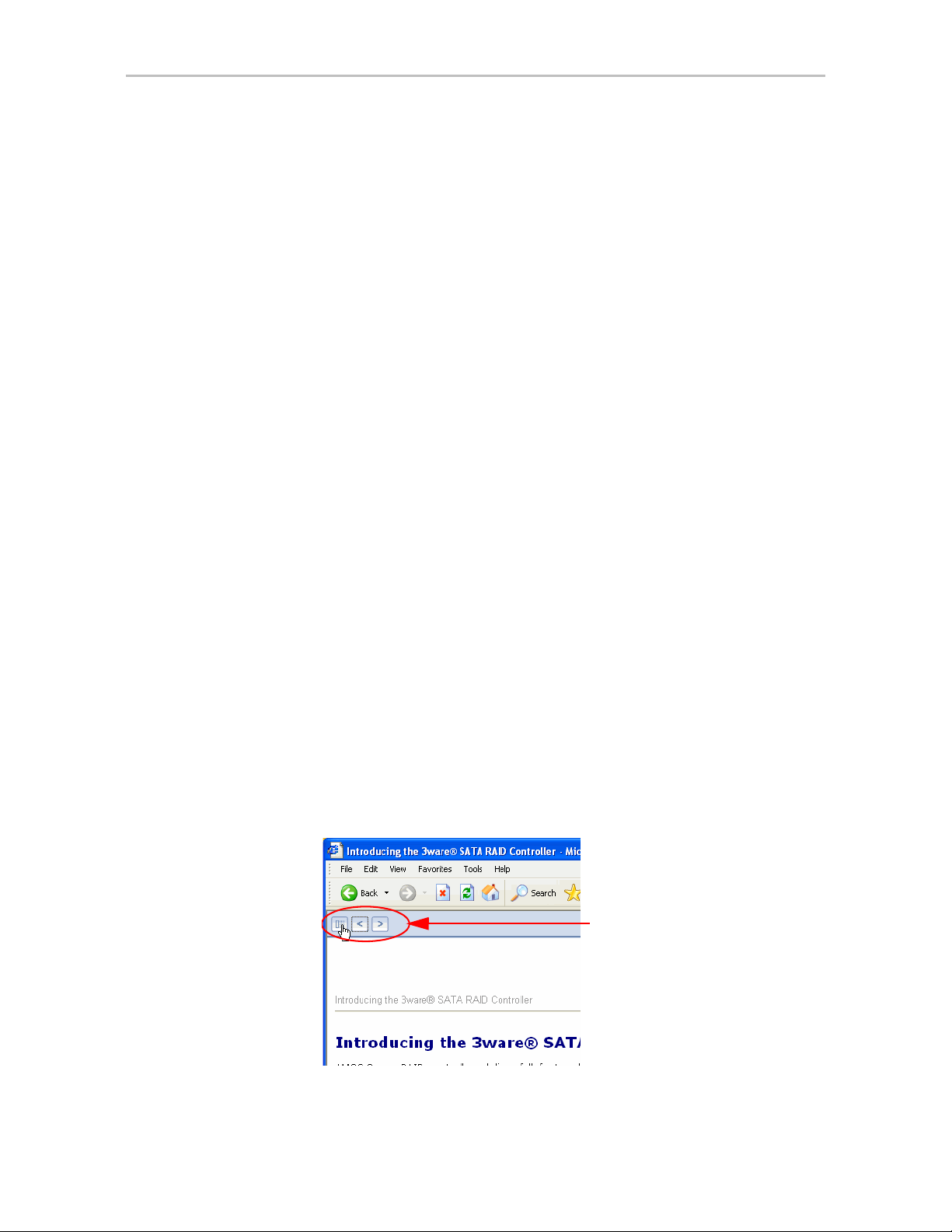
the navigation pane by clicking the
Figure 1. Navigation Button in the 3ware HTML Bookshelf Window
Show Navigation button at the left.
Click the Show Navigation
button to display the Table of
Contents
viii 3ware Serial ATA RAID Controller User Guide for Mac OS X
Page 9

Getting Started with Your 3ware RAID Controller
Setting up your 3ware RAID controller involves these main steps:
• Physically Install the RAID Controller and Drives
• Install the 3ware Driver and Disk Management Software
• Configure a RAID Unit
• Set Up Management and Maintenance Features
Tip: When you are first setting up your system, you may want to review
“System Requirements” on page 5.
1
Physically Install the RAID Controller and Drives
T o install your controller and drives, fo llow the instructions in the installation
guide that came with your 3ware Sidecar Kit. If you do not have a hardcopy of
the installation manual, it is available in the 3ware Documentation folder on
your 3ware CD, and you can download it from the 3ware website at http://
www.3ware.com/support/userdocs.asp.
For drive installation, see the instructions that came with your 3ware Sidecar
or other external enclosure. If you are installing drives in a computer case,
follow the manufacturer’s instructions.
Install the 3ware Driver and Disk Management Software
Instructions for installing the drivers and software are in the 3ware Sidecar
Kit with the 9650SE-4LPME: Installation Guide and in Appendix B, “Driver
and Software Installation”
Configure a RAID Unit
If you would like more information about what RAID level to choose for your
situation, review the information under “Understanding RAID Concepts and
Levels” on page 6. Then turn to “Configuring a New Unit” on page 33.
www.3ware.com 1
Page 10

Chapter 1. Getting Started with Your 3ware RAID Controller
Set Up Management and Maintenance Features
3ware RAID controllers include a number of features to help you manage and
maintain the controller and your configured units. The default settings for
these features allow you to begin using your newly configured units right
away. You can review and change these features as a final step in your initial
setup, or you can make changes to them later, at your convenience. These
features include:
• Controller and unit policies, such as Auto Rebuild, Auto Verify, use of
write cache, use of queueing mode, and selection of a StorSave profile.
• Email notification of alarms and other events
• Schedules for when background tasks will be performed, to minimize the
impact on day-to-day performance during peak usage times. (Background
tasks include rebuild, verify, initialize, migrate, and self-test.)
Details about these features are described in this documentation. When you
first set up your controller, you may want to review these sections in
particular:
• “Configuring Your Controller” on page 27
• “Setting Unit Policies” on page 42
• “Setting Background Task Rate” on page 75
Initial Settings for Policies and Background Tasks
The table below lists the default settings for policies and background tasks.
These settings are used if you do not explicitly change the policy settings.
Table 2: Default Settings for Policies and Background Tasks
Policy Default Value Where to Change
Controller-Level Settings
(For details, see “Configuring Your Controller” on page 27
Auto-Rebuild Enabled 3DM, CLI
Auto-Carving Disabled 3DM, CLI
Auto-Detect Enabled CLI
Carve Size or Factor 2048 GB 3DM, CLI
Unit-Level Settings
(For details, see “Setting Unit Policies” on page 42)
Auto Verify Disabled 3DM, CLI
Continue on Source Error
During Rebuild
2 3ware Serial ATA RAID Controller User Guide for Mac OS X
Disabled 3DM, CLI
Page 11
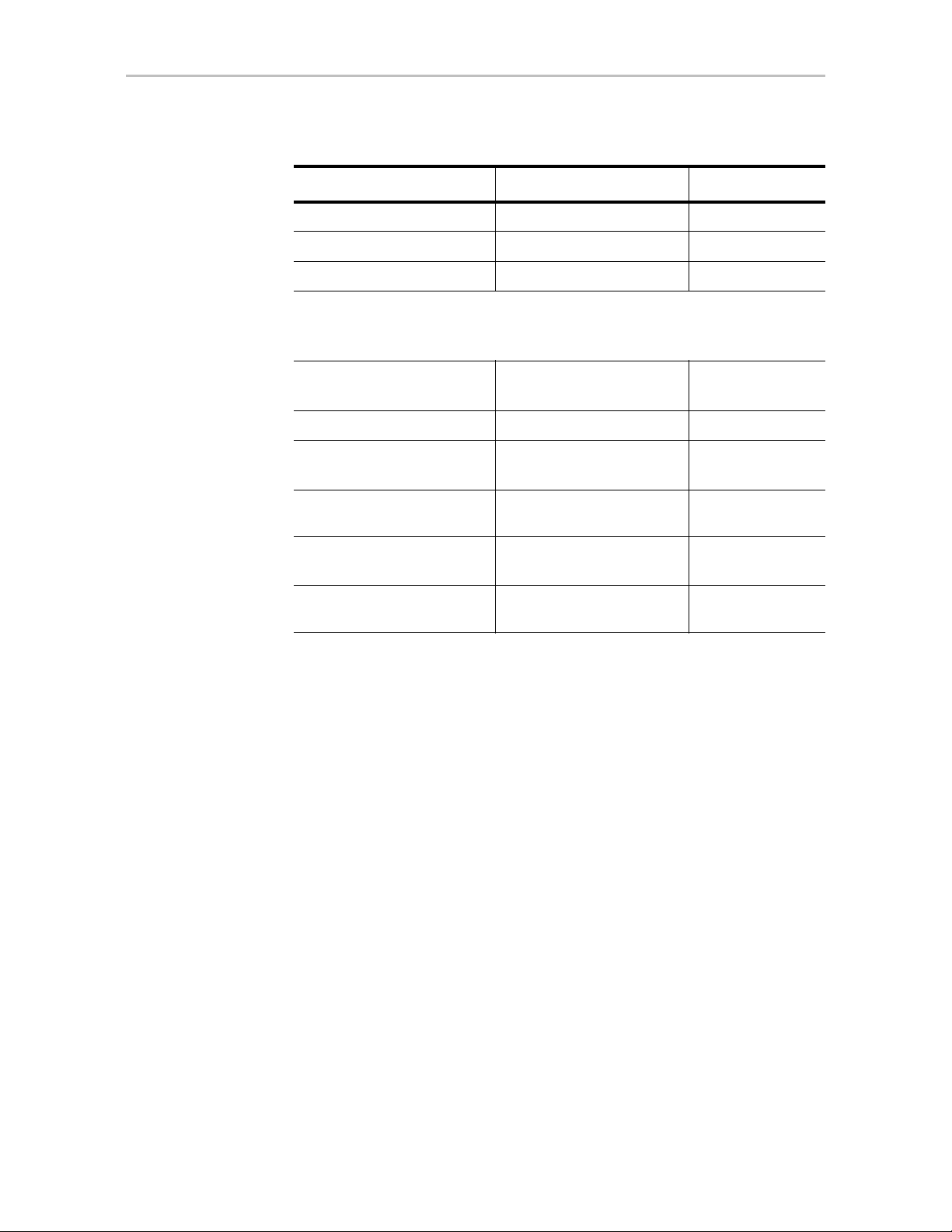
Table 2: Default Settings for Policies and Background Tasks
Policy Default Value Where to Change
Queuing (NCQ) Enabled 3DM, CLI
StorSave Profile Protection 3DM, CLI
Write Cache Enabled 3DM, CLI
Background Task Settings
(For details, see “Scheduling Background Tasks” on page 76 and “Setting
Background Task Rate” on page 75)
Verify Task Schedules
Daily,
starting at 12:00 am
3DM, CLI
and running for 24 hours
Follow Verify Task Schedule No 3DM, CLI
Rebuild Task Schedules
Daily,
starting at 12:00 am
3DM, CLI
and running for 24 hours
Follow Rebuild T ask
Schedule
Self-test Task Schedules
a
No 3DM, CLI
Daily, starting at 12:00 am
3DM, CLI
and running for 24 hours
Follow Self-test Task
Schedule
Yes 3DM, CLI
a. Although the default Self-test Task Schedule is for 24 hours, self-test
tasks are run only at the beginning of that time period and take just a few
minutes. For more information about task schedules, see “Scheduling
Background Tasks” on page 76.
www.3ware.com 3
Page 12

2
Introducing the 3ware® SATA RAID Controller
T w o 3ware SATA RAID controllers are available for use with Mac OS X: the
9650SE-4LPME and the 9590SE-4ME. Both of these controllers are 4-lane
(x4) PCI Express® cards and can be installed in any of the available x4 or x8
PCI Express slots on your Mac Pro or Power Mac® G5. (The x16 slot is
normally reserved for your graphics card.)
These 3ware RAID controllers feature:
• Support for up to 4 SATA drives.
• AMCC’s remote management software, 3ware Disk Manager 2 (3DM
which simplifies storage configuration and management through a web
browser.
• An enhanced firmware platform that allows future upgrades.
• Advanced RAID features for greater data protection and management.
• PCI Express connectivity
• Transfer rate of up to 2.5Gbps per lane
• 7th generation StorSwitch(TM) technology
• Support for 3Gbps and Native Command Queuing (NCQ)
• StorSave profiles that let you set the desired level of protection versus
performance for a unit
• Drive Locate which allows you to easily identify a drive in the 3ware
Sidecar enclosure by blinking the LED associated with it
• The ability to define a carving size to be used when carving units into
volumes.
Note: The 9650SE-4LPME and 9590SE-4ME are each part of a 3ware Sidecar Kit,
which includes the 3ware Sidecar Enclosure. Information about setting up the
3ware Sidecar itself is included in the installation guide that comes with the 3ware
Sidecar Kit. Make sure you get the appropriate RAID controller model for the type of
Mac you own (Mac Pro or Power Mac G5).
®
2)
4 3ware Serial ATA RAID Controller User Guide for Mac OS X
Page 13

System Requirements
Drive Requirements
Drives must be 3.5" and meet SATA-1 or SATA-2 standards.
A list of drives that have been tested is available at
http://www.3ware.com/products/compatibility_sata2.asp
Operating System and Computer Requirements
Mac OS 10.4.6 or later, running on a Mac Pro or a Power Mac G5 (PowerPCbased) with PCI Express.
Other Requirements
System Requirements
• 3DM 2 (3ware Disk Manager) displays information in a browser. It
requires one of the following browsers:
• Safari™ 2.0.4 or newer
• Firefox® 1.5.0.4 or newer
In addition:
• JavaScript must be enabled
• Cookies must be enabled
• For best viewing, screen resolution should be 1024 x 768 or greater,
with 16-bit color or greater.
Note: When using the 3ware HTML Bookshelf, if you use the Safari browser, the
Back button does not step you back through pages accessed in the bookshelf. You
can use the navigation features built into the bookshelf, however, including the
Previous/Next arrows at the top of each page, the breadcrumbs, and the Contents/
Index/Search pane at the left.
Tip: The Back button does work correctly when viewing the 3ware HTML Bookshelf
in Firefox.
For a complete listing of features and system requirements, refer to the 3ware
SATA RAID Controller datasheets, available from the website at http://
www.3ware.com/products.
www.3ware.com 5
Page 14

Chapter 2. Introducing the 3ware® SATA RAID Controller
Understanding RAID Concepts and Levels
3ware RAID controllers use RAID (Redundant Array of Inexpensive Disks)
to increase your storage system’s performance and provide fault tolerance
(protection against data loss).
This section organizes information about RAID concepts and configuration
levels into the following topics:
• “RAID Concepts” on page 6
• “Available RAID Configurations” on page 7
• “Determining What RAID Level to Use” on page 10
RAID Concepts
The following concepts are important to understand when working with a
RAID controller:
•
Arrays and Units. In the storage industry, the term “array” is used to
describe two or more disk drives that appear to the operating system as a
single unit. When working with a 3ware RAID controller, “unit” is the
term used to refer to an array of disks that is configured and managed
through the 3ware software. Single-disk units can also be configured in
the 3ware software.
•
Mirroring. Mirrored arrays (RAID 1) write data to paired drives
simultaneously . If one drive fails, the data is preserved on the paired
drive. Mirroring provides data protection through redundancy. In
addition, mirroring using a 3ware RAID controller provides improved
performance because 3ware’s TwinStor technology reads from both
drives simultaneously.
•
Striping. Striping across disks allows data to be written and accessed on
more than one drive, at the same time. Striping combines each drive’s
capacity into one large volume. Striped disk arrays (RAID 0) achieve
highest transfer rates and performance at the expense of fault tolerance.
•
Distributed Parity . Parity works in combination with striping on RAID 5.
Parity information is written to each of the striped drives, in rotation.
Should a failure occur, the data on the failed drive can be reconstructed
from the data on the other drives.
Hot Swap. The process of exchanging a drive without having to shut
•
down the system. This is useful when you need to exchange a defective
drive in a redundant unit.
For definitions of other terms used throughout the documentation, see the
“Glossary”.
6 3ware Serial ATA RAID Controller User Guide for Mac OS X
Page 15
Available RAID Configurations
RAID is a method of combining several hard drives into one unit. It offers
fault tolerance and higher throughput levels than a single hard drive or group
of independent hard drives. RAID levels 0, 1, 10 and 5 are th e most popular.
AMCC's 3ware controllers support RAID 0, 1, 5, 10, JBOD and Single Disk.
The information below provides a more in-depth explanation of the different
RAID levels.
For how to configure RAID units, see “Configuring a New Unit” on page 33.
RAID 0
RAID 0 provides improved performance, but no fault tolerance. Since the
data is striped across more than one disk, RAID 0 disk arrays achieve high
transfer rates because they can read and write data on more than one drive
simultaneously. The stripe size is configurable during unit creation. RAID 0
requires a minimum of two drives.
When drives are configured in a striped disk array (see Figure 2), large files
are distributed across the multiple disks using RAID 0 techniques.
Understanding RAID Concepts and Levels
Striped disk arrays give exceptional performance, particularly for data
intensive applications such as video editing, computer-aided design and
geographical information systems.
RAID 0 arrays are not fault tolerant. The loss of any drive results in the loss of
all the data in that array, and can even cause a system hang, depending on
your operating system. RAID 0 arrays are not recommended for high
availability systems unless additional precautions are taken to prevent system
hangs and data loss.
Figure 2. RAID 0 Configuration Example
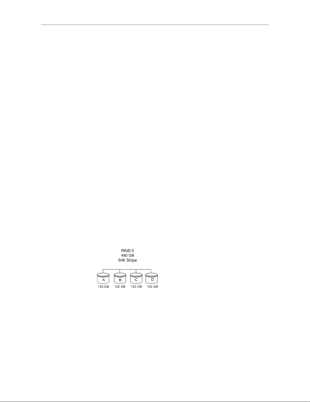
RAID 1
RAID 1 provides fault tolerance and a speed advantage over non-RAID disks.
RAID 1 is also known as a mirrored array. Mirroring is done on pairs of
drives. Mirrored disk arrays write the same data to two different drives using
RAID 1 algorithms (see Figure 3). This gives your system fault tolerance by
preserving the data on one drive if the other drive fails. Fault tolerance is a
basic requirement for critical systems like web and database servers.
www.3ware.com 7
Page 16
Chapter 2. Introducing the 3ware® SATA RAID Controller
3ware uses a patented technology, TwinStor®, on RAID 1 arrays for
improved performance during sequential read operations. With TwinStor
technology, read performance is twice the speed of a single drive during
sequential read operation.
The adaptive algorithms in TwinStor technology boost performance by
distinguishing between random and sequential read requests. For the
sequential requests generated when accessing large files, both drives are used,
with the heads simultaneously reading alternating sections of the file. For the
smaller random transactions, the data is read from a single optimal drive head.
Figure 3. RAID 1 Configuration Example
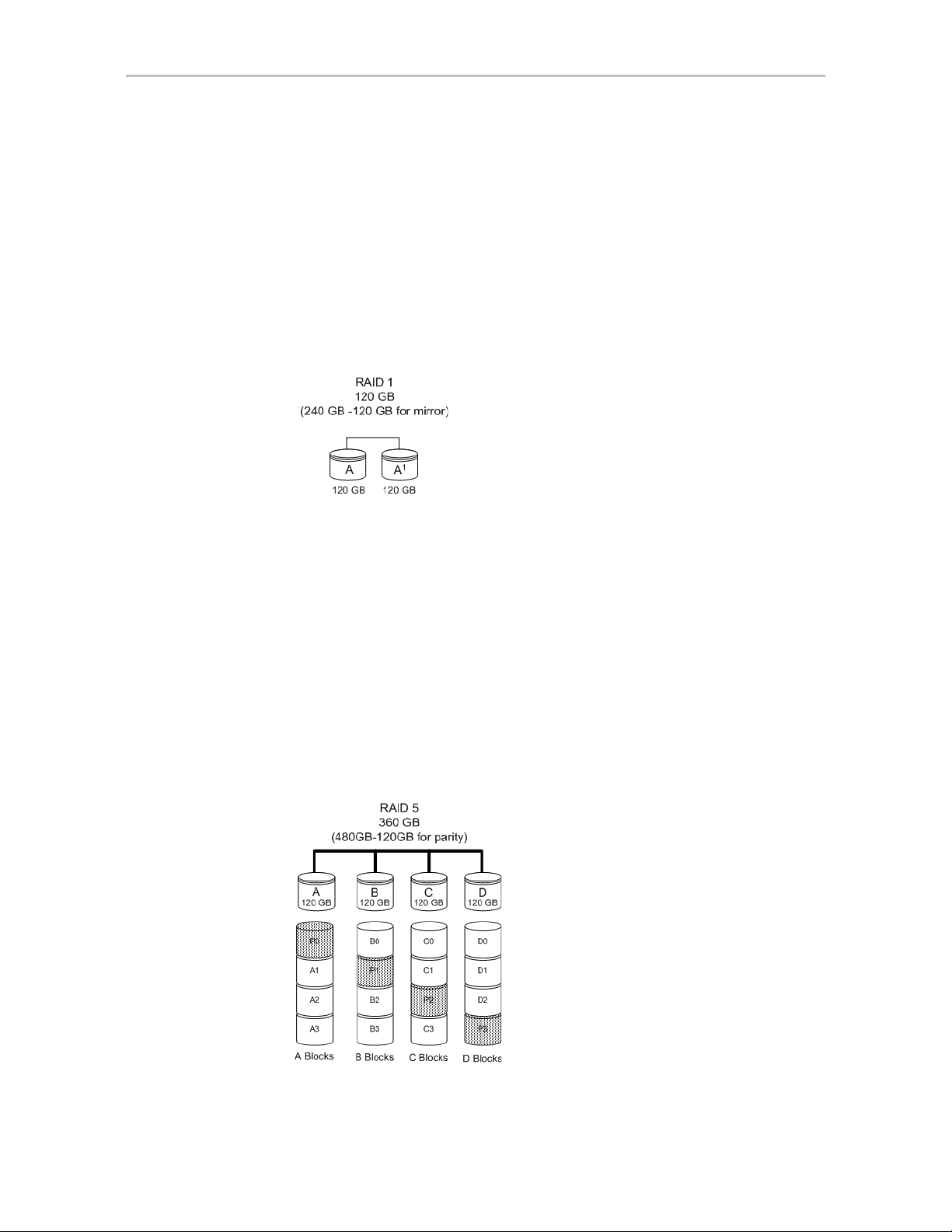
RAID 5
RAID 5 provides performance, fault tolerance, high capacity, and storage
efficiency. It requires a minimum of three drives and combines striping data
with parity (exclusive OR) to restore data in case of a drive failure.
Performance and efficiency increase as the number of drives in a unit
increases.
Parity information is distributed across all of the drives in a unit rather than
being concentrated on a single disk (see Figure 4). This avoids throughput
loss due to contention for the parity drive.
RAID 5 is able to tolerate 1 drive failure in the unit.
Figure 4. RAID 5 Configuration Example
8 3ware Serial ATA RAID Controller User Guide for Mac OS X
Page 17
Understanding RAID Concepts and Levels
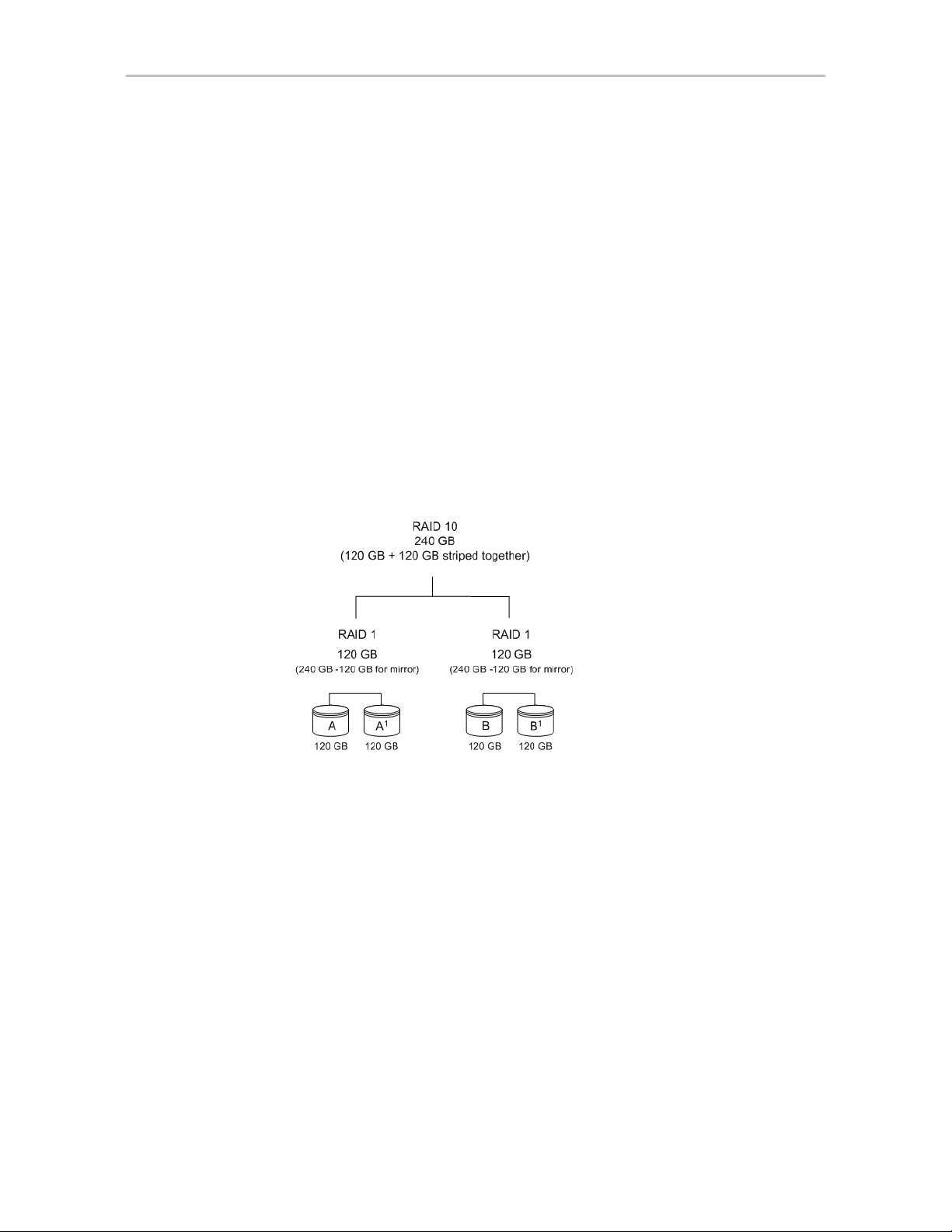
RAID 10
RAID 10 is a combination of striped and mirrored arrays for fault tolerance
and high performance.
When drives are configured as a striped mirrored array, the disks are
configured using both RAID 0 and RAID 1 techniques, thus the name RAID
10 (see Figure 5). A minimum of four drives are required to use this
technique. The first two drives are mirrored as a fault tolerant array using
RAID 1. The third and fourth drives are mirrored as a second fault tolerant
array using RAID 1. The two mirrored arrays are then grouped as a striped
RAID 0 array using a two tier structure. Higher data transfer rates are
achieved by leveraging TwinStor and striping the arrays.
In addition, RAID 10 arrays offer a higher degree of fault tolerance than
RAID 1 and RAID 5, since the array can sustain multiple drive failures
without data loss. Please note that if both halves of a mirrored pair in the
RAID 10 array fail, then all of the data will be lost.
Figure 5. RAID 10 Configuration Example
Single Disk
A single drive can be configured as a unit through 3ware software. (3DM 2 or
CLI). Like disks in other RAID configurations, single disks contain 3ware
Disk Control Block (DCB) information and are seen by the OS as available
units.
Single drives are not fault tolerant and therefore not recommended for high
availability systems unless additional precautions are taken to prevent system
hangs and data loss.
Hot Spare
A hot spare is a single drive, available online, so that a redundant unit can be
automatically rebuilt in case of drive failure.
www.3ware.com 9
Page 18

Chapter 2. Introducing the 3ware® SATA RAID Controller
Determining What RAID Level to Use
Your choice of which type of RAID unit (array) to create will depend on your
needs. You may wish to maximize speed of access, total amount of storage, or
redundant protection of data. Each type of RAID unit offers a different blend
of these characteristics.
The following table provides a brief summary of RAID type characteristics.
Table 3: RAID Configuration Types
RAID Type Description
RAID 0 Provides performance, but no fault tolerance.
RAID 1 Provides fault tolerance and a read speed advant age over non-
RAID disks.
RAID 5 This type of unit provides performance, fault tolerance, and high
storage efficiency. RAID 5 units can tolerate one drive failing
before losing data.
RAID 10 A combination of striped and mirrored units for fault tolerance
and high performance.
Single Disk Not a RAID type, but supported as a configuration.
Provides for maximum disk capacity with no redundancy.
You can create one or more units, depending on the number of drives you
have installed.
Using Drive Capacity Efficiently
To make the most efficient use of drive capacity, it is advisable to use drives
of the same capacity in a unit. This is because the capacity of each drive is
limited to the capacity of the smallest drive in the unit.
The total unit capacity is defined as follows:
10 3war e Ser ial AT A RAID Con tr oller User Guide for Mac OS X
Page 19
3ware Tools for Configuration and Management
Table 4: Drive Capacity
RAID Level Capacity
Single Disk Capacity of the drive
RAID 0 (number of drives) X (capacity of the smallest drive)
RAID 1 Capacity of the smallest drive
RAID 5 (number of drives - 1) X (capacity of the smallest drive)
Storage efficiency increases with the number of disks:
storage efficiency = (number of drives -1)/(number of drives)
RAID 10 (number of drives / 2) X (capacity of smallest drive)
Through drive coercion, the capacity used for each drive is rounded down so
that drives from differing manufacturers are more likely to be able to be used
as spares for each other. The capacity used for each drive is rounded down to
the nearest GB for drives under 45 GB (45,000,000,000 bytes), and rounded
down to the nearest 5 GB for drives over 45 GB. For example, a 44.3 GB
drive will be rounded down to 44 GB, and a 123 GB drive will be rounded
down to 120 GB. For more information, see the discussion of drive coercion
under “Creating a Hot Spare” on page 40.
3ware Tools for Configuration and
Management
3ware software tools let you easily configure the drives attached to your
3ware RAID controller, specifying which drives should be used together as a
RAID unit and the type of RAID configuration you want, and designating hot
spares for use if a drive degrades.
3ware provides the following tools for use in configuring and managing units
attached to the 3ware controller:
• 3DM 2 (3ware Disk Manager)
3DM runs in the background on the controller’s host system, and can be
accessed through a web browser to provide ongoing monitoring and
administration of the controller and associated drives. It can be used
locally or remotely.
For details about working with 3DM, see “3DM 2 (3ware Disk Manager)
Introduction” on page 14.
Using 3DM to manage your 3ware RAID controller is discussed
throughout this manual.
www.3ware.com 11
Page 20

Chapter 2. Introducing the 3ware® SATA RAID Controller
3DM 2 is the current version of the 3ware Disk Manager . Th roughout this
documentation, it is referred to interchangeably as 3DM and 3DM 2.
• 3ware CLI (Command Line Interface)
The 3ware CLI provides the functionality available in 3DM through a
Command Line Interface. You can view unit status and version
information and perform maintenance functions such as adding or
removing drives, and reconfiguring RAID units online. You can also use
it to remotely administer controllers in a system.
The 3ware CLI is described in 3ware Serial ATA RAID Controller CLI
Guide and in the 3ware HTML Bookshelf.
Monitoring, Maintenance, and Troubleshooting Feat ures
Several 3ware RAID controller features aid in monitoring and
troubleshooting your drives.
•
SMART Monitoring (Self-Monitoring, Analysis and Reporting
Technology) automatically checks a disk drive's health every 24 hours
and reports potential problems. This allows you to take proactive steps to
prevent impending disk crashes. SMART data is checked on all disk
drives (array members, single disks, and hot spares). Monitoring of
SMART thresholds can be turned on and off in 3DM. (For details, see
“V iewin g SMART Data About a Drive” on page 67.)
•
Verification. The verify task verifies all redundant units, and checks for
media errors on single disks, spares, and RAID 0 unit members. If the
disk drive is part of a redundant unit, error locations that are found and are
deemed repairable are rewritten with the redundant data. This forces the
drive firmware to reallocate the error sectors accordingly. (For more
information, see “About Verification” on page 70.)
•
Error Correction. Bad sectors can be dynamically repaired through error
correction (Dynamic Sector Repair). Reallocation of blocks is based
intelligently on the location of the block in relation to the stripe.
•
Scheduled Background Tasks. Initialize, rebuild, verify, and self-test
tasks can all be run in the background, at scheduled times. This lets you
choose a time for these tasks to be run when it will be least disruptive to
your system. You can also define the rate at which background tasks are
performed, specifying whether I/O tasks should be given more processing
time, or background rebuild and verify tasks should be given more
processing time. (For more information, see “Scheduling Background
Tasks” on page 76.)
•
Write Cache. Write cache can be enabled or disabled using 3DM 2 and
CLI. When write cache is enabled, data will be stored in system cache,
12 3war e Ser ial AT A RAID Con tr oller User Guide for Mac OS X
Page 21

Monitoring, Maintenance, and Troub leshooting Features
3ware controller cache, and drive cache before the data is committed to
disk. This allows the system to process multiple write commands at the
same time, thus improving performance. However when data is stored in
cache, it could be lost if a power failure occurs. With a Battery Backup
Unit (BBU) installed, the cache stored on the 3ware controller can be
restored. A UPS (uninterruptable power supply) is recommended when
using write cache. (For more information, see “Enabling and Disabling
the Unit Write Cache” on page 43.)
•
StorSave™ Profiles allow you to set the level of protection versus
performance that is desired for a unit when write cache is enabled. (For
more information, see “Setting the StorSave Profile for a Unit” on
page 46.)
•
Drive and Unit Identification. Units or drives in enclosures can be
2
identified by flashing LEDs. When the I
C port on the controller has been
connected to a chassis with a Chassis Control Unit (CCU), such as the
3ware Sidecar, you can issue drive Locate commands that blink the LEDs
for particular drives, so that you can quickly identify which drive needs to
be checked or replaced. For more information, see “Locating a Drive by
Blinking Its LED” on page 81.
•
Auto Rebuild. For times when you do not have a spare available, setting
the Auto Rebuild policy allows rebuilds to occur with an available drive
or with a failed drive. (For more information, see “Setting the Auto
Rebuild Policy” on page 30.)
www.3ware.com 13
Page 22
3
3DM 2 (3ware Disk Manager) Introduction
Note: 3DM 2 includes software developed by the OpenSSL Project for use in the
OpenSSL Toolkit (http://www.openssl.org/).
3ware Disk Manager 2 (3DM 2) allows you to manage and view the status of
your 3ware RAID controller and associated drives.
There are two parts to 3DM: a process, that runs in the background on the
computer where you have installed your 3ware controller, and a web
application that can be used to access it. When the 3DM process is running,
you can use your browser to go to 3DM application pages, where you can
view status information about the controller and RAID units, create RAID
units, and perform other administrative and maintenance tasks locally or
remotely.
T wo levels of access to 3DM are provided: user and administrator . Users have
view-only access, and can check the status of drives and units. Administrators
can view and make changes, using 3DM to configure RAID units and
designate hot spares, and to perform maintenance tasks on RAID units.
In this section, information is organized into the following topics:
• Browser Requirements for 3DM
• 3DM 2 can be installed from the 3ware CD that came with your 3ware
RAID controller. You can also download the current version from the
website at http://www.3ware.com/support/download.asp. Details about
the installation are described in “Driver and Software Installation” on
page 165.
• Starting 3DM and Logging In
• Working with the 3DM Screens
• Setting Up 3DM Preferences
For details about the settings and fields on each of the 3DM 2 screens, see
“3DM 2 Reference” on page 88.
For additional information about managing and maintaining 3ware controllers
using 3DM, see the remaining chapters in this guide.
14 3war e Ser ial AT A RAID Con tr oller User Guide for Mac OS X
Page 23
Browser Requirements for 3DM
3DM runs in most current web browsers. Tested and supported browsers
include:
• Safari 2.0.4 or newer
• Firefox 1.5.0.4 or newer
Additional requirements:
• JavaScript must be enabled
• Cookies must be enabled
• For best viewing, use a screen resolution of 1024 X 768 or greater , and set
colors to 16 bit color or greater.
Note: Because 3DM may be viewed in different browsers, the format and style of
the 3DM browser windows illustrated in this documentation are examples only. The
actual “look” of the windows will depend on the browser you use.
Browser Requirements for 3DM
3DM 2 can be installed from the 3ware CD that came with your 3ware RAID
controller. You can also download the current version from the website at
http://www.3ware.com/support/download.asp. Details about the installation
are described in “Driver and Software Installation” on page 165.
3DM must be installed on the system in which the controller is installed. 3DM
does not have to be installed on a remote system in order to remotely manage
the 3ware controller; you simply enter the correct URL into a browser on the
remote system. You will need to enable remote access first, however.
Starting 3DM and Logging In
Normally after installation, the 3DM process starts automatically when you
start your system.
It is a good idea to leave the 3DM process running on the system that contains
your 3ware RAID controller. That way email alerts can be sent by 3DM, and
administrators can manage the controller remotely , if remote administration is
enabled.
When 3DM is running in the background on your computer, you can access
the 3DM web application through your browser to check status information
and manage your 3ware RAID controller.
If the 3DM process does not start automatically, you can start it manually, as
described under “Starting and Stopping the 3DM Process Manually on the
Macintosh” on page 17. You will know if the process is not running, because
www.3ware.com 15
Page 24
Chapter 3. 3DM 2 (3ware Disk Manager) Introduction
when you try to use the 3DM web application, you will get a page not found
error.
If you want to check the status of a controller from a different computer, see
“Viewing 3DM Remotely Using a Web Browser” on page 18.
Logging In to the 3DM Web Application
When the 3DM process is running in the background, you can log into the
3DM application pages using a brows er.
Two levels of access are provided:
• Users can check the status of the controller, units, and attached drives.
• Administrators can check status, configure, and maintain the units and
drives on the 3ware controller.
Note: Administrator and User status in 3DM is not related to Administrator/User
settings in the operating system.
To log in to the 3DM web application
1 You can start the 3DM 2 web application in one of the following ways:
• In the Finder, choose
Connect to 3DM2.webarchive.
Applications > AMCC, and then double-click
Your browser will open and go to the URL for 3DM 2.
OR
• Open your browser and enter the URL for your system.
The default URL is http://localhost:888/
You can also replace “localhost” with the IP address of the computer
that contains the 3ware controller. For example:
http://<IP address>:888/
Note: If you receive a page not found message, make sure you
entered the URL correctly. If you did, 3DM may not be running in the
background. You can start it manually, as described under “Starting
3DM on the Macintosh” on page 75.
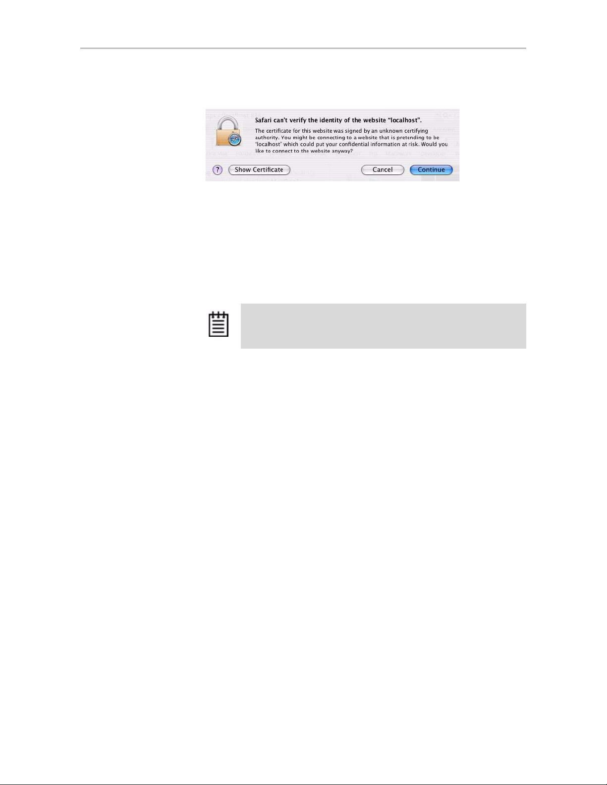
2 The first time you start 3DM, when the security certificate message
displays, click
Show Certificate and accept the certificate so that you do
not see the security message each time you start 3DM.
16 3war e Ser ial AT A RAID Con tr oller User Guide for Mac OS X
Page 25
Starting 3DM and Logging In
Figure 6. Security Certificate Message from Browser
(You can also click Continue, in which case you will see this message the
next time you start 3DM.)
3 When the 3DM logon screen appears, select whether you are a
Administrator.
4 Enter your password and click
Login.
User or
If you are logging in for the first time after installing 3DM, the default
password for both User and Administrator is
Note: If you forget the passwords, uninstalling and reinstalling 3DM
resets the passwords to 3ware
.
3ware.
Starting and Stopping the 3DM Process Manually on the Macintosh
The 3DM process should start automatically after it has been installed. If it
does not, you can start it manually.
To see if the 3DM process is already running
• Open a Terminal window and type:
ps -ax | grep 3dm2 | grep -v grep
If 3DM is running, you will see it included on the output line that
displays.
To stop the 3DM process so you can restart it
1 In a Terminal window, type:
sudo killall 3dm2
2 When prompted for it, enter your administrator password.
3 Wait for a minute or so before verifying that the process has been
terminated. (It can take a couple of minutes for the process to be stopped.)
www.3ware.com 17
Page 26
Chapter 3. 3DM 2 (3ware Disk Manager) Introduction
4 Verify that the process has been terminated by typing
ps -ax | grep 3dm2 | grep -v grep
The output line should not include 3DM.
5 If the process is still running, contact AMCC/3ware T echnical Support for
assistance.
To start the 3DM process manually
1 Open a Terminal window and type:
sudo /usr/sbin/3dm2
2 Enter your administrator password, when prompted for it.
The 3DM process starts.
3 Open your browser and enter the URL for your system.
The default URL is http://localhost:888/
You can also replace “localhost” with the IP address of the computer that
contains the 3ware controller. For example: http://<IP address>:888/
Viewing 3DM Remotely Using a Web Browser
When remote administration is enabled on the 3DM 2 Settings page, you can
use 3DM to check status and administer your 3ware RAID controller from a
browser on any computer, over an internet connectio n.
You do not need to install the 3DM software on the remote computer.
To connect to 3DM2 through your web browser
• In the address line of your browser, enter the URL or IP of the system
containing the 3ware RAID controller.
If you do not know the URL or IP for the system, you can contact your
network administrator, or open a Terminal window and type
Note: When using 3DM to access a remote system, the time on the
local system must match the time on the file server. If the time varies
by more than 30 minutes, it will not be possible to remotely monitor
the system (you will not be able to log in). If you are in a different time
zone, you must first change the time of the local system to match the
time of the remote system.
ifconfig.
18 3war e Ser ial AT A RAID Con tr oller User Guide for Mac OS X
Page 27
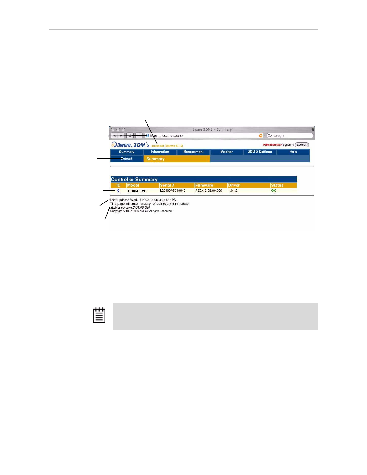
Working with the 3DM Screens
3DM’s features are organized on a series of pages you view in your browser.
After you log in to 3DM, the Summary page shows a list of controllers
installed in the computer at the URL you specified.
Figure 7. 3DM Main Screen
Working with the 3DM Screens
System name and operating system.
Address of the
system to which
you are
connected.
Menu bar
Message bar
List of
controllers on
the system
Time of last
page refresh
Version of 3DM
The menu bar across the top of the screen gives you access to other pages in
3DM. You can move between pages by using the menu bar, or by clicking a
link on the page.
The main area of the page provides summary or detail information about your
3ware RAID controller and the resources connected to it.
As you work in 3DM, the Messages area just below the menu bar displays
information about the results of commands you have selected.
Tip: If you have a question about something you see on the scre en, just clic k the
Help button in the menu bar.
Online Help
www.3ware.com 19
Page 28
Chapter 3. 3DM 2 (3ware Disk Manager) Introduction
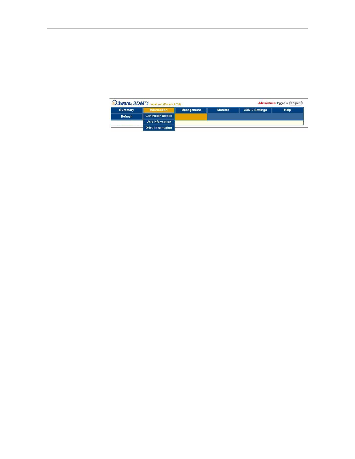
3DM Menus
The 3DM menu bar groups access to a number of 3DM pages on menus, and
provides direct link access to others.
Figure 8. 3DM Menu Bar
Status information is available from the Information menu. You can view
controller, unit, and drive information for a particular controller.
The
Management menu gives you access to tasks used for managing
controller-level settings (background task rate, unit polices such as enabling
of unit write cache, and controller settings that affect all units managed by the
controller), tasks that can be scheduled (rebuild, verify, and self-test), and
maintenance of individual units. Unit configuration can also be done through
the
Management > Maintenance page.
The
Monitor menu gives you access to the Alarms page, the BBU page, and
the Enclosure Summary page. The
Alarms page shows a list of alarms,
including the specific alarm message, and the exact date and time it occurred.
The
BBU page shows the status of a Battery Backup Unit (BBU), if one is
installed, and allows you to test the battery. (BBU is not supported on the
9590SE-4ME.) The
Enclosure Summary page provides lists the enclosures
connected to the controller and lets you drill down for more detailed status
information about each.
3DM 2 Settings page lets you set preferences, including email
The
notification for alarms, passwords, page refresh frequency, whether remote
access is permitted, and the incoming port which 3DM will use for listening.
Help lets you access information about using 3DM. The Help is context-
sensitive, so you first see information about the page you now have in view. A
Table of Contents and Index are available to help you find other information.
20 3war e Ser ial AT A RAID Con tr oller User Guide for Mac OS X
Page 29
Working with the 3DM Screens
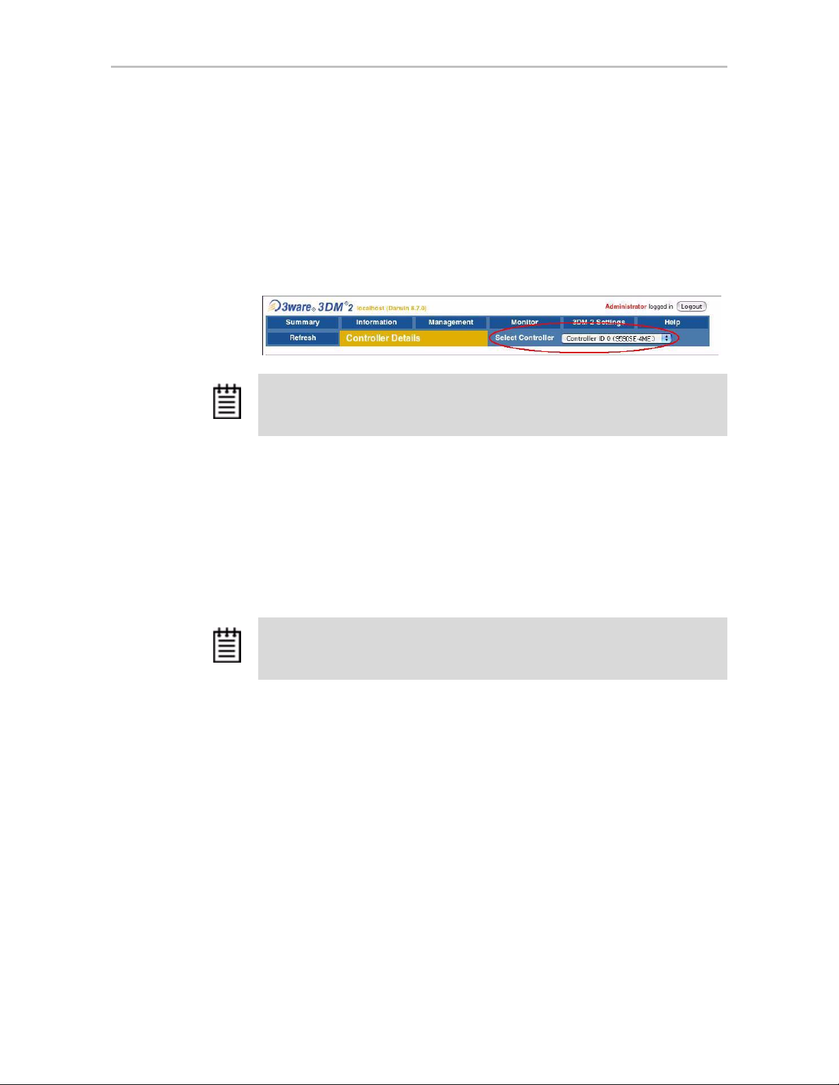
Viewing Information About Different Controllers
If you have more than one 3ware RAID controller in the system, you select
the one you want to see details about from the drop-down list at the right of
the menu bar.
This drop-down is available on all pages that provide controller-specific
features.
Figure 9. 3DM Controller Selection Drop-down
Note: Throughout these instructions, the term current controller is used to refer to
the controller which is currently selected in this drop-down list.
Refreshing the Screen
You can refresh the data on the screen at any time by clicking Refresh Page
in the menu bar. This causes 3DM to update the information shown with
current information from the controller and associated drives.
Automatic refreshes can also be set. For details, see “Setting the Frequency of
Page Refreshes” on page 26.
Note: If you click Refresh on the browser window instead of on the 3DM menu bar,
you will be taken back to the Summary page.
3DM Screens and What They're Used For
The table below shows a list of the pages you work with in 3DM and
describes what they are used for. Details about each page and the fields and
features on it are provided in Chapter 8, “3DM 2 Reference”. The page names
in the table provide links to details about that page.
In addition, the step-by-step instructions provided in the chapters on
configuring and maintaining your RAID controller and units explain how to
do particular tasks in 3DM.
www.3ware.com 21
Page 30
Chapter 3. 3DM 2 (3ware Disk Manager) Introduction
Table 5: List of 3DM Pages
3DM Page Description
Controller Summary
page
Provides basic information about each 3ware RAID
controller in your system.
To see this page, click Summary in the menu bar.
Controller Details
page
Provides detailed information about the current controller.
To see this page, choose Information > Controller
Details from the menu bar.
Unit Information page Shows a list of the units on the current cont ro ll er and
provides summary information about each unit.
T o see this p age, choose Information > Unit Information
from the menu bar or click an ID number on the Controller
Summary.
Unit Details page Shows details about a particular unit.
To see this page, click an ID number on the Unit
Information page.
Drive Information
page
Shows a list of drives on the current controller and
provides summary information about each drive.
To see this page, choose Information > Drive
Information from the menu bar.
Drive Details window Shows the SMART data for a specific drive, and shows
additional detail information for the drive.
To see this page, click the Port # for a drive on the Drive
Information page.
Controller Settings
page
Lets you view settings that affect the units on the current
controller and change some of those settings.
Controller-level settings that can be changed include
background task rate, Auto Rebuild, Auto-Carving, and
Carve Size. Some additional policies are shown that can
only be changed in the CLI.
Unit-level settings include specifying the StorSave Profile
and enabling or disabling the Write Cache, Auto-Verify,
Continue on Error During Rebuild, and Queuing.
To see this page, choose
Management > Controller
Settings from the menu bar.
Scheduling page Lets you view and change the schedule for tasks that
affect all units on the current controller.
To see this page, choose Management > Scheduling
from the menu bar.
22 3war e Ser ial AT A RAID Con tr oller User Guide for Mac OS X
Page 31

Setting Up 3DM Preferences
Table 5: List of 3DM Pages
3DM Page Description
Maintenance page Lets you configure new units and make changes to
existing units.
To view this page, choose Management > Maintenance
from the menu bar.
Alarms page Shows a list of alarms, including the specific alarm
message, and the exact date and time it occurred.
T o view this p age, choose Monitor > Alarms on the menu
bar.
Battery Backup page Shows the status of a Battery Backup Unit (BBU), if one is
installed, and allows you to test the battery.
To view this page, choose Monitor > Battery Backup on
the menu bar.
(BBUs are not supported on the 9590SE-4ME.)
Enclosure Summary
page
Enclosure Details
page
3DM 2 Settings page Lets you set preferences, including email notification for
Lists the enclosures attached to your 3ware controller.
To view this page, choose
Support
Shows details about a particular enclosure, including
status information. You can also use this p age to blink the
LED for a particular drive.
To view this page, click the ID number of the Enclosure on
the Enclosure Summary page.
alarms, passwords, page refresh frequency, whether
remote access is permitted, and the incoming port which
3DM will use for listening.
To view this page, click 3DM 2 Settings on the menu bar.
on the menu bar.
Setting Up 3DM Preferences
The 3DM 2 Settings page lets you define preference settings that affect the
overall operation of 3DM. Most of these settings are specified initially during
installation of 3DM.
On the 3DM 2 Settings page you can perform the following tasks:
• Setting and Changing 3DM Passwords
• Managing E-mail Event Notification
• Enabling and Disabling Remote Access
• Setting the Incoming Port #
• Setting the Frequency of Page Refreshes
Monitor > Enclosure
www.3ware.com 23
Page 32

Chapter 3. 3DM 2 (3ware Disk Manager) Introduction
Setting and Changing 3DM Passwords
3DM provides different access levels for users and administrators.
The Administrator access level allows the user to fully configure 3DM. The
User access level allows the user to view pages within 3DM. These passwords
work independently of each other.
The default password for both the User and Administrator is “3ware”.
Passwords are case sensitive.
You can only change passwords if you are logged in as Administrator. If you
change the Administrator password, you will be automatically logged out, and
must log back in with the new password.
To set or change the password
1 Click
2 On the 3DM 2 Settings page, in the
3DM 2 Settings on the 3DM menu bar.
password you want to change:
User or Administrator.
Password section, select the type of
3 Type the current password in the Current Password field.
If you are changing the password for the first time, the factory-set default
password is
3ware.
4 Enter the new password in the New Password field and again in the
Confirm New Password field.
5 Click the
Change Password button to enact the change.
Note: If you forget your password, you can uni nstall 3DM and then
reinstall it. This will reset the password to the default password,
.
3ware
Managing E-mail Event Notification
3DM can notify you when the 3ware RAID controller requires attention, such
as when a disk unit becomes degraded and is no longer fault tolerant.
E-mail event notification can only occur while 3DM is running, so it is
recommended that the 3DM process be left running in the background on the
system that contains the 3ware RAID controller.
When events occur, notification can be e-mailed to one or more recipients.
You can specify the type of events for which notifications will be sent by
selecting the severity:
24 3war e Ser ial AT A RAID Con tr oller User Guide for Mac OS X
Page 33

Setting Up 3DM Preferences
• Information will send e-mails for all events
•
Warning will send e-mail for events with severity of Warning and Error.
Error will send e-mail for events with severity of Error only.
•
Events are listed on the 3DM
Alarms page.
Event notification can be set up during 3DM installation, and can be changed
on the 3DM 2 Settings page.
To set up event notification
1 Click
2In the
3DM 2 Settings on the menu bar.
E-mail Notification section of the 3DM 2 Settings page, enter or
change the settings you want.
• Enable or Disable all notifications.
• Set the severity level of events for which e-mail notifications are sent.
• Specify the email address of the sender. This will appear in the
“From” field of the e-mail.
• Enter the e-mail address(es) to which notifications are sent. (Separate
multiple addresses with a comma (,) or a semicolon (;).
• Enter the SMTP server name or IP of the mail server for the computer
where the 3ware controller is installed.
• If your email server requires authentication, enter the Mail Server
Login and Password.
3 Click
Save E-mail Settings.
To send a test message
You can send a test message to make sure you’ve entered the e-mail
notification settings correctly.
• Click
Send Test Message.
Enabling and Disabling Remote Access
When remote access is enabled, a user can connect to 3DM over the internet
or an intranet, to check status or administer the controller and associated
drives. (See “Viewing 3DM Remotely Using a Web Browser” on page 18.)
If remote access is disabled and a user attempts to connect to 3DM remotely,
they will see the following error message: “Remote Access to 3DM has been
disabled. Please connect using the local machine by entering “localhost” in
the URL bar.”
Remote access can be enabled or disabled on the 3DM 2 Settings page.
www.3ware.com 25
Page 34

Chapter 3. 3DM 2 (3ware Disk Manager) Introduction
To enable or disable remote access
1 Click
2In the
3DM 2 Settings on the menu bar.
Remote Access section of the 3DM 2 Settings page, select either
Enabled or Disabled in the Allow Remote Connections field.
The page refreshes, and a message at the top of the screen confirms that
remote access has been enabled or disabled.
Setting the Incoming Port #
You can set the port which 3DM uses to listen for incoming messages. If you
are not sure which port would be the best to use, leave this set to the default
port of 888.
To set the incoming port
1 Click
2In the
3 Click
3DM 2 Settings on the menu bar.
Incoming Port # section of the 3DM 2 Settings page, enter the port
number in the
Change Port.
Listening Port field.
The page refreshes, and a message at the top of the screen confirms that
the listening port has been changed.
Setting the Frequency of Page Refreshes
Since the status of the drives attached to your 3ware RAID controller can
change while you are viewing information about them in 3DM, it is important
to refresh the page information regularly. That way you can be assured that
the information you see in 3DM is current.
You can manually refresh the information on a page by clicking
Page
in the menu bar. But you can also have 3DM refresh the information on
a regular basis.
To set the frequency of page refreshes
1 Click
2In the
3DM 2 Settings on the menu bar.
Page Refresh section of the 3DM 2 Settings page, select how often
you want the page to be refreshed in the
Note: If you do not want 3DM to refresh the screen automatically,
Never in the Minutes Between Refresh field. You can
select
then refresh manually by clicking Refresh on your web browser.
Minutes Between Refresh field.
Refresh
26 3war e Ser ial AT A RAID Con tr oller User Guide for Mac OS X
Page 35
Configuring Your Controller
This section describes how to view details about the controller, check its
status, and change configuration settings that affect the controller and all of
the drives connected to it. It is organized into the following sections:
• V iewing Information About a Controller
• V iewi ng Controller Policies
• Setting the Auto Rebuild Policy
• Using Auto-Carving for Multi LUN Support
• Setting the Size of Volumes Created with Auto-Carving
Note: Background task rate is also set for all units on a controller. For information
about setting the task rate, see “Setting Background Task Rate” on page 75.
4
Viewing Informa t ion About a Controller
You can check the controller model, serial number, firmware and driver
versions, and the status of the 3ware RAID controller in your computer.
If you have more than one controller in your system, you can easily vie w
information about each one using 3DM. For example, if you have two 3ware
Sidecars attached to your Mac Pro or Power Mac G5, you will have a different
3ware controller for each one.
To see details about a controller in 3DM
1 Start 3DM and log in as an administrator.
The 3DM Controller Summary page appears, listing all the 3ware
controllers installed in your system.
The right-most column of the list shows the status of each controller.
www.3ware.com 27
Page 36

Chapter 4. Configuring Your Controller
Figure 10. Controller Summary Page
2 To see more details about a particular controller, click the ID link for that
controller to display the Controller Details page.
Figure 11. Controller Details Page
Tip: If you are managing controllers remotely, the list of controllers is
for the machine with the IP or URL you entered in the browser
address bar.
To see information about a different controller in the 3DM pages
If you have more than one controller in the system, you can switch between
them by selecting the one you want from the
Select Controller drop-down
list at the right of the menu bar. This drop-down is available on all pages that
provide controller-specific features.
When you select a different controller from this list, the page in view changes,
to reflect the details for the controller you selected.
Note: Throughout this documentation, the term current controller is used to refer to
the controller currently selected in this drop-down list.
28 3war e Ser ial AT A RAID Con tr oller User Guide for Mac OS X
Page 37

About Controller Policies
The following policies affect all units and drives on a controller and can be
adjusted as appropriate for your equipment. Controller policies are shown at
the bottom of the Controller Settings page in 3DM (Figure 12).
Auto Rebuild. Determines whether the Auto Rebuild policy is enabled or
•
disabled. When disabled, degraded units can only be rebuilt with
designated spares. When enabled, the controller firmware will attempt to
rebuild a degraded unit if there is no spare, using either an available drive
or a failed drive.
•
Auto-Carving. Determines whether the auto-carving policy is enabled or
disabled. When it is enabled, any unit larger than a specified size (known
as the carve size) is broken into multiple volumes that can be addressed
by the operating system as separate volumes. The default carve size is 2
TB.
This auto-carving feature is sometimes referred to as multi-LUN, where
each volume that is created is referred to as a “LUN.”
About Controller Policies
•
Carve Size. Sets the size for dividing up units into volumes when Auto-
Carving is enabled. This setting can be between 1024 GB and 2048 GB.
Some additional policies can be set at the unit level. For more information,
see “Setting Unit Policies” on page 42.
Viewing Controller Policies
You can view the current state of controller policies in 3DM, in the Other
Controller Settings
Figure 12). Only the Auto Rebuild, Auto-Carving, and Carve Size policies
can be changed on this page. The other policies do not apply to the Macintosh.
For a summary of the initial default settings, see Table 2, “Default Settings for
Policies and Background Tasks,” on page 2.
section at the bottom of the Controller Settings page (see
www.3ware.com 29
Page 38

Chapter 4. Configuring Your Controller
To view controller policies in 3DM
• Choose
Figure 12. 3DM Controller Settings Page
Management > Controller Settings from the menu bar.
Setting the Auto Rebuild Policy
The Auto Rebuild policy determines how the controller firmware will attempt
to rebuild degraded units.
When Auto Rebuild is disabled, only spares will be automatically used to
rebuild degraded units. When Auto Rebuild is enabled, the firmware will
select drives to use for automatically rebuilding a degraded unit using the
following priority order.
• Smallest usable spare.
• Smallest usable unconfigured (available) drive.
• Smallest usable failed drive.
Enabling Auto Rebuild allows you to add a drive to the controller and have it
be available for a rebuild, without having to specify it as a spare.
30 3war e Ser ial AT A RAID Con tr oller User Guide for Mac OS X
Page 39

Using Auto-Carving for Multi LUN Support
With Auto Rebuild enabled, if you accidentally disconnect a drive (causing
the controller to see it as a failed drive) and then reconnect it, the controller
will automatically try to use it again.
To enable Auto Rebuild through 3DM
1 Choose
Management > Controller Settings from the menu bar in 3DM.
2 In the Other Controller Settings section at the bottom of the screen, select
Enabled option for Auto Rebuild.
the
The page refreshes, and a message at the top confirms the change you
have made.
Using Auto-Carving for Multi LUN Support
When the Auto-Carving policy is on, any unit larger than a specified size
(known as the carve size) is created as multiple volumes that can be addressed
by the operating system as separate volumes. These chunks are sometimes
known as multiple LUNs (logical units). However, throughout the 3ware
documentation, they are referred to as volumes.
For example, using the default carve size of 2 TB, if the unit is 2.5 TB then it
will contain two volumes, with the first volume containing 2TB and the
second volume containing 0.5 TB. If the unit is 5.0 TB then it will contain 3
volumes, with the first two volumes containing 2 TB each and the last volume
containing 1TB.
Each volume can be treated as an individual disk with its own file system. The
default carve size is 2 TB; you can change this to a setting in the range of
1TB to 2 TB (1024 GB to 2048 GB). 3ware firmware supports a maximum of
8 volumes per controller, up to a total of 16 TB.
If you are migrating a unit to a size that is larger than the ca rve siz e and autocarving is on, multiple volumes will be created.
Note: Using auto-carving can have an impact on performance.
32-bit and 64-bit You must turn on the Auto-Carving policy before creating the
unit. Units created with this policy turned off will not be affected by a change
to the policy. If the policy is turned off later, units that have been carved into
volumes will retain their individual volumes; existing data is not affected.
www.3ware.com 31
Page 40

Chapter 4. Configuring Your Controller
To use auto-carving
1 Enable the auto-carving feature.
In 3DM, enable Auto-Carving at the bottom of the
Controller Settings
page.
Management >
2 Create a new unit or migrate an existing unit to include the drives you
want to use.
If the combined capacity of the drives exceeds the carve size, a number of
volumes will be created.
3 Verify the creation of the volumes.
In 3DM 2, the number of volumes is shown on the Unit Details page.
4 Verify that the volumes appear in the operating system. They will appear
as additional drives.
Notes:
• When volumes have been created through auto-carving, they cannot be
deleted except by deleting the unit.
• Changing the auto-carve policy does not affect existing units.
Setting the Size of Volumes Created with Auto-Carving
If you create units over 2 TB in size and use auto-carving to divide them into
multiple volumes, you can control the size of the volumes to be created by
setting the carve size to use. The carve size can be between 1TB (1024 GB)
and 2 TB (2 048 GB); the default is 2 TB.
When you change this policy, it applies to units you create in the future.
Existing units will not be affected.
To set the carve size in 3DM
1 Choose
2 In the Other Controller Settings section at the bottom of the screen, in the
Management > Controller Settings from the menu bar in 3DM.
Carve Size field, enter the size you want (between 1024 GB and
2048 GB) to use and click
Submit.
The page refreshes, and a message at the top confirms the change you
have made.
32 3war e Ser ial AT A RAID Con tr oller User Guide for Mac OS X
Page 41

Configuring Units
This section includes information and procedures on configuring units
attached to your 3ware RAID controller. It is organized into the following
topics:
• Configuring a New Unit
• Creating a Hot Spare
• Naming a Unit
• Setting Unit Policies
• Changing An Existing Configuration by Migrating
(RAID Level Migration or Online Capacity Expansion)
• Deleting a Unit
• Removing a Unit
• Moving a Unit from One Controller to Another
• Adding a Drive
• Removing a Drive
• Rescanning the Controller
5
Configuring a New Unit
When you configure a new unit, you specify some details related to the type
of RAID configuration that you want, and others that enable or disable
features.
This section first provides an overview of the different settings you can
specify during configuration and then provides step-by-step instructions for
creating a unit.
Configuration Options When Creating a Unit
This section provides an overview of the choices you have when configuring
a new unit. For step-by-step instructions, see “Creating a Unit” on page 35.
When you configure a new unit, you specify the following:
• Drives to be included in the unit
• Type of configuration (RAID Level)
www.3ware.com 33
Page 42

Chapter 5. Configuring Units
• Name of the unit (optional)
• Stripe size, if appropriate for the RAID level
• Unit policies that affect how the unit will be handled
You can make some types of changes to the RAID configuration later, and
you can change the unit name and the unit policies. For details, see “Changing
An Existing Configuration by Migrating” on page 48 and “Setting Unit
Policies” on page 42.
Drives to be included in the unit
You may include from one to four drives in the unit, depending on the numb er
of drives available. (For information about how many drives to select for a
given RAID level, see “Determining What RAID Level to Use” on page 10.)
Available drives are those that are not currently part of a unit. If you want to
use drives that are currently part of a different unit, you must first delete that
unit to make the drives available. (For details, see “Deleting a Unit” on
page 53.) If drives are listed under “Incomplete Drives and Others,” they must
be deleted before they can be used.
If you want to add drives to be used in the unit, see “Adding a Drive” on
page 56.
Type of configuration (RAID Level)
Available configuration types include RAID 0, RAID 1, RAID 5, RAID 10,
and Single Disk. For information about the different RAID levels, see
“Understanding RAID Concepts and Levels” on page 6.
Note: Creating a unit erases all data on all drives. Although creating a RAID 1
(mirror) creates a unit that will have a duplicate of data on both drives after it is put
in use, creating a RAID 1 cannot be used to make a backup copy of data that
currently exists on a single drive unless you migrate from a RAID 1 to two individual
single disks.
Name of the unit (optional)
Units can be given names. These names will be visible in 3DM.
Stripe size, if appropriate for the RAID level
In general, smaller stripe sizes are better for sequential I/O, such as video, and
larger stripe sizes are better for random I/O (such as databases).
Striping size is not applicable for RAID 1, because it is a mirrored array
without striping.
34 3war e Ser ial AT A RAID Con tr oller User Guide for Mac OS X
Page 43

Configuring a New Unit
Using the default stripe size of 64KB usually gives you the best performance
for mixed I/Os. If your application has some specific I/O pattern (purely
sequential or purely random), you might want to experiment with a smaller or
larger stripe size.
Unit policies
Several unit policies are set when you create a new unit:
• Write Cache (enabled, by default)
• Drive Queuing (disabled, by default)
• Auto Verify (disabled, by default)
• Continue on Source Error During Rebuild (disabled, by default)
• StorSave Profile (Protection, by default)
You can change all of these policies after the unit has been created.
For a summary of what these policies do, see the discussion under “Setting
Unit Policies” on page 42. For how to adjust each one, see the procedures
later in this chapter.
Creating a Unit
In 3DM, creating a unit starts from the Management > Maintenance page
(Figure 13).
Figure 13. 3DM Maintenance Page
www.3ware.com 35
Page 44

Chapter 5. Configuring Units
To create a unit
1 In 3DM, choose
Management > Maintenance.
2 In the Av ailable Drives list, select the drives you want to include in the
unit by marking the checkbox in front of the Port number for each one.
If you are creating single drive units (single disks or hot spares), you can
configure multiple drives at once.
3 Click
Create Unit.
A window similar to the one below shows the drives you selected, and
lets you specify configuration settings.
Figure 14. Configuring a Unit in 3DM
4In the Type field, select the RAID configuration you want.
5 If stripe size applies to the RAID type you select, select a
Stripe Size.
(Stripe size does not apply to RAID 1.)
6 Optional: In the
Name box, enter a name for the unit (up to 21 characters,
including dashes and underscores).
7 Make changes to the unit policies, as desired. You can enable or disable
Write Cache, Auto Verify, and Continue on Source Error During
the
Rebuild
. You can also set the StorSave policy.
For details about these settings, see “Setting Unit Policies” on page 42.
8 Click
OK.
The new unit appears in the Unit Maintenance list at the top of the page
and the operating system is notified of the new unit.
If you have auto-carving enabled and the size of your unit exceeds the
carve size, you may see multiple unit volumes in your operating system.
For details, see “Using Auto-Carving for Multi LUN Support” on
page 31.
9 When the Mac OS displays a “Disk Insertion” message, go on to
“Initializing (Formatting) and Partitioning Units”, below.
36 3war e Ser ial AT A RAID Con tr oller User Guide for Mac OS X
Page 45

Configuring a New Unit
Initializing (Formatting) and Partitioning Units
After you create a unit, it needs to be formatted, partitioned, and mounted by
the operating system before it can be used.
Note: “Initialization” of the unit by your operating system is different from
“initialization” of a unit by 3ware. Initialization under your operating system
will format your disk, erasing any existing data in the process. Initialization
under 3ware does not erase data; it puts redundant data on the drives of
redundant units into a known state so that data can be recovered in the
event of a disk failure. For more information, see “About Initialization” in
the 3ware Serial ATA RAID Controller User Guide for Mac OS X.
When you create a unit through 3DM 2, the Mac OS X recognizes that a new
disk is available, and displays a message asking what you want to do. (If this
message does not appear, you can start the Disk Utility manually from the
Finder and skip to step 2.)
To initialize and partition your unit
1 In the Mac OS message, click
Figure 15. Disk Insertion Message from the Mac OS
Initialize.
2 When the Macintosh Disk Utility window opens, find and select the drive
that represents your RAID unit.
Figure 16. Macintosh Disk Utility Window with New RAID Unit
www.3ware.com 37
Page 46

Chapter 5. Configuring Units
3 In the Disk Utility Window, select the Partition tab.
Figure 17. Macintosh Disk Utility Window, Partition Tab
4 In the Volume Scheme column, click Current to show the drop-down
menu and select the number of partitions that you want your RAID unit to
have.
Tip: If you only want one volume, select 1 Partition. (Each partition will
appear as a separate drive on your computer.)
Figure 18. Selecting the Number of Volumes in Disk Utility
5 On the right, specify a volume name and then click Partition.
It is a good idea to use a unique name, although Mac OS X will allow you
to give the same name to more than one partition.
If you have questions about what Format to select, see the Apple
documentation.
38 3war e Ser ial AT A RAID Con tr oller User Guide for Mac OS X
Page 47
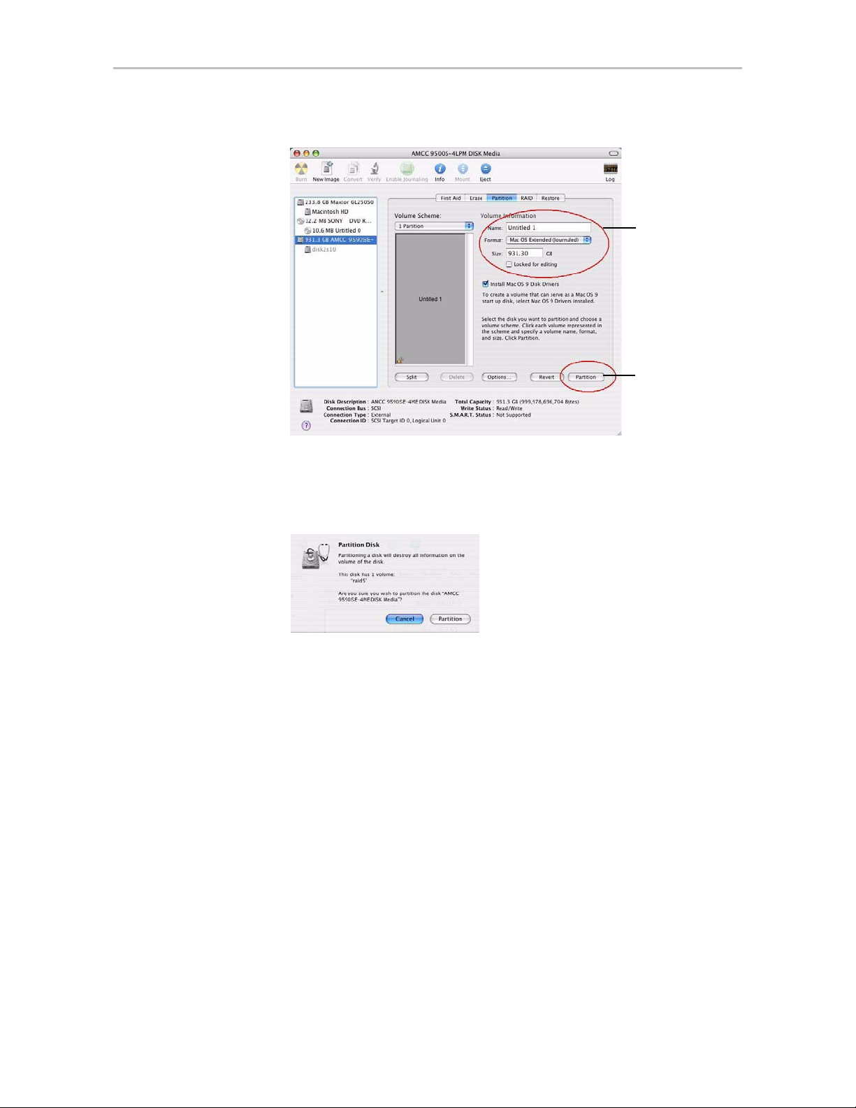
Configuring a New Unit
Figure 19. Defining the Volume in the Macintosh Disk Utility
a) Enter a
unique
name
b) Click
Partition
6 When a message asks you to confirm you want to partition the disk, click
Partition.
Figure 20. Confirmation Message to Create the Partition
You will see a series of messages appear toward the bottom of the Disk
Utility window as the RAID unit is first partitioned and then formatted.
This may take a couple of minutes, depending on the size of the drives in
your RAID unit.
www.3ware.com 39
Page 48

Chapter 5. Configuring Units
Figure 21. Macintosh Disk Utility Showing Partitioning Progress
Messages
appear here
as the unit is
formatted.
When the partitioning is complete, icons for each new volume appear on
your desktop. They are now ready for use.
You can now close the Macintosh Disk Utility window . Your RAID unit is
ready for use.
Creating a Hot Spare
You can designate an available drive as a hot spare. If a redundant unit
degrades and a hot spare the size of the degraded disk (or larger) is available,
the hot spare will automatically replace the failed drive in the unit without
user intervention.
Note: When a hot spare replaces a failed drive, an event notification is generated
and appears in the list of alarms in 3DM. You can also have 3DM send you an email
about this. See “Managing E-mail Event Notification” on page 24.
It is a good idea to create a hot spare after you create a redundant unit.
In order to replace a failed drive, a hot spare must have the same or larger
storage capacity than the drive it is replacing.
The Auto Rebuild policy allows automatic rebuilding to occur with available
drives that are not designated as spares. For more information, see “Setting
the Auto Rebuild Policy” on page 30.
40 3war e Ser ial AT A RAID Con tr oller User Guide for Mac OS X
Page 49

Naming a Unit
Note: 3ware’s 9000 series RAID controllers use drive coercion so that drives from
differing manufacturers and with slightly different capacities are more likely to be
able to be used as spares for each other. Drive coercion slightly decreases the
usable capacity of a drive that is used in redundant units.
The capacity used for each drive is rounded down to the nearest GB for drives
under 45 GB (45,000,000,000 bytes), and rounded down to the nearest 5 GBytes
for drives over 45 GB. For example, a 44.3 GB drive will be rounded down to 44
GBytes, and a 123 GB drive will be rounded down to 120 GBytes.
If you have 120 GB drives from different manufacturers, chances are that the
capacity varies slightly. For example, one drive might be 122 GB, and the other 123
GB, even though both are sold and marketed as “120 GB drives.” 3ware drive
coercion uses the same capacity for both of these drives so that one could replace
the other.
If you need to add a drive to be used as the hot spare, follow the instructions
under “Adding a Drive” on page 56.
To specify a hot spare
1 In 3DM, choose
2 In the Av ailable Drives list, select the drive you want as a hot spare by
marking the checkbox in front of it’s Port number.
3 Click
4 In the dialog box that appears, select the configuration type
5 Click
You will see the spare appear at the top of the page, under
Maintenance
Naming a Unit
Units can be given unique names to more easily identify them. A unit can be
assigned a name when it is created. It can also be named or renamed at a later
time.
To name or rename a unit through 3DM
1 Make sure the appropriate controller is selected in the drop-down list at
the right of the menu bar.
Management > Maintenance.
Create Unit.
Spare.
Ok.
Unit
.
2 Choose
3In the
Management > Controller Settings from the menu bar in 3DM.
Unit Names section of the Controller Settings page, locate the unit
for which you want to change the name.
www.3ware.com 41
Page 50

Chapter 5. Configuring Units
4 In the text box, enter or type over the name shown. A name can be up to
21 characters, and can include dashes and underscores.
5 Click the
Save Names button.
Note: If you want to cancel your change before saving it, click the
Reset Names
Setting Unit Policies
The following polices are set when you create a unit, and can be adjusted later
through settings on the
Details about adjusting each policy are described on the following pages.
Unit Write Cache. Determines whether write cache is enabled for the
•
unit. When the write cache is enabled, data is stored locally on the drive
before it is written to disk, allowing the computer to continue with its next
task. This provides the most efficient access times for your computer
system. When disabled, the computer will wait for the drive to write all
the data to disk before going on to its next task. For details, see “Enabling
and Disabling the Unit Write Cache” on page 43.
This feature interacts with functionality of the BBU, if you have one, and
with the unit’s StorSave profile. For details, see “Enabling and Disabling
the Unit Write Cache” on page 43.
button.
Management > Controller Settings pages of 3DM.
Auto Verify. Determines whether Auto Verify is enabled for the unit.
•
When enabled, the Auto Verify policy causes a verify task to be
performed automatically once every 24 hours. This feature is designed to
make it easier to insure regular verification of units. If verify schedules
have been enabled, then Auto Verify will run only in the scheduled verify
time slots. When Auto Verify is disabled, you must manually specify
when you want to verify a unit, even if you have set a verify schedule. For
details, see “Setting Auto Verify for a Unit” on page 44.
•
Continue on Source Error During Rebuild. Determines whether ECC
errors are ignored when they are encountered during a rebuild. (ECC
errors are an indication of errors that have occurred on a particular drive
since it was last read.) When not enabled, a rebuild will abort upon
encountering an ECC error and the unit will be set to Degraded. For
details, see “Setting Continue on Source Error During Rebuild” on
page 45.
Queuing. Determines whether NCQ (Native Command Queuing) is
•
enabled for the unit. When enabled for drives that support it, this policy
can improve performance. For details, see “Enabling and Disabling
Queuing for a Unit” on page 46.
42 3war e Ser ial AT A RAID Con tr oller User Guide for Mac OS X
Page 51

Setting Unit Policies
• StorSave Profile. Determines what StorSave profile is used for the unit.
Three profiles are available: Protection, Balanced, and Performance. For
details, see “Setting the StorSave Profile for a Unit” on page 46.
Figure 22. Unit Policies on Controller Settings Page in 3DM
Enabling and Disabling the Unit Write Cache
Write cache is used to store data locally in memory on the drive before it is
written to the disk drive media, allowing the computer to continue with its
next task. This improves performance. However, there may be instances when
you want the computer to wait for the drive to write all the data to disk before
going on to its next task. In this case, you must disable the write cache.
Note: If write cache is enabled, in the event of a power failure, the data in the write
cache will be lostif you do not have a Battery Backup Unit (BBU).To avoid a sudden
power failure if you do not have a BBU, it is advisable to have an Uninterruptable
Power Supply (UPS). (BBU is not supported on the 9590SE-4ME.)
Write cache can be turned on or off for individual units in 3DM without
changing the configuration or losing data from the drives.
If you have a BBU (Battery Backup Unit) installed on the controller, the
battery preserves the contents of the controller cache memory for a limited
period of time (up to 72 hours) in the event of a system power loss. When a
BBU is installed, if the battery is not “Ready,” write cache is disabled and
cannot be enabled.
www.3ware.com 43
Page 52

Chapter 5. Configuring Units
The unit's StorSave profile can also determine whether the write cache can be
enabled or disabled. A warning message will be given if the change is not
permitted due to the StorSave setting and the state of the unit.
Note: If the Write Cache checkbox is disabled (not selectable), check to see if the
unit has degraded. If a unit has a StorSave policy of “Protect” and the unit degrades,
the policy prevents write cache from being re-enabled until the unit has been rebuilt.
To enable or disable unit write cache through 3DM
1 Choose
2In the
Management > Controller Settings from the menu bar in 3DM.
Unit Policies section of the Controller Settings page, check the
Write Cache box to enable it for the designated unit.
The page refreshes, and a message at the top confirms the change you
have made.
If your system has no BBU, a message will caution you about enabling
write cache.
Setting Auto Verify for a Unit
The Auto Verify policy causes verify tasks to be performed automatically.
This feature is designed to make verification of units easier.
If Auto Verify is set and there is no schedule set up for verify tasks, then the
controller firmware can initiate a verify task once every 24 hours. If verify
time windows are scheduled, then the controller will only start an automatic
verify task during the scheduled time windows. (For information about
schedules, see “Scheduling Background Tasks” on page 76.)
If Auto Verify is not set, you must manually specify when you want to run a
verify, on the 3DM
Controller Settings page. If a schedule is set for verify,
then the verify that you manually start will only run during the scheduled
time.
You can set the Auto Verify policy while creating a unit through 3DM or you
can change the setting later using the following method.
44 3war e Ser ial AT A RAID Con tr oller User Guide for Mac OS X
Page 53

To set the Auto Verify policy for an existing unit
Setting Unit Policies
1 Choose
2In the
Auto Verify box for the appropriate unit. (To disable this policy, uncheck
Management > Controller Settings from the menu bar in 3DM.
Unit Policies section of the Controller Settings page, check the
the box.)
The page refreshes, and a message at the top confirms the change you
have made.
Setting Continue on Source Error During Rebuild
The Continue on Source Error During Rebuild policy is available for units
which are redundant. (For units which are not redundant, this option is not
shown on the screen.) When this policy is set, ECC (Error Correcting Code)
errors are ignored when they are encountered during a rebuild. (ECC errors
are typically defects that have been detected in the drive since initialization.)
When this policy is not set, if a unit is rebuilding, the rebuild will abort when
it encounters an ECC error and the unit will be set back to Degraded.
Since enabling this policy could result in the loss of some source data in the
event of source errors, the default is to not enable this policy. Select this
option only if you want to ensure that a rebuild will complete successfully
without manual intervention. If the rebuild fails and
Error During Rebuild
is not selected, then you have the option to start
another rebuild manually . After completing a rebuild with this policy enabled,
it is recommended that you execute a file system check when the rebuild
completes. On Mac OS X, you can do this using the First Aid tab in the Disk
Utility—select the disk on the left and then click
encounters problems, you can then use the
Repair Disk option on the same
screen.
Continue on Source
Verify Disk. If verification
T o se t the Continue on Source Error During Rebuil d policy in 3DM
1 Choose
2In the
Management > Controller Settings from the menu bar in 3DM.
Unit Policies section of the Controller Settings page, check the
boxes to select the policies you want to be in effect for each unit
The page refreshes, and a message at the top confirms the change you
have made.
www.3ware.com 45
Page 54

Chapter 5. Configuring Units
Enabling and Disabling Queuing for a Unit
Some drives support NCQ (Native Command Queuing), a feature that can
result in increased performance for applications that require a lot of random
access of data (usually server-type applications). This is accomplished by
causing command reordering to be done on the drive.
In order to make use of NCQ, the feature must be enabled at both the drive
and the controller.
You can see whether NCQ is supported and enabled for a particular drive in
the Drive Details window. For details, see “Drive Details window” on
page 95.
Note: Not all drives support NCQ. If a drive does not support NCQ, the policy
setting for the controller is ignored.
To enable or disable queuing for a unit through 3DM
1 Choose
2In the
Management > Controller Settings from the menu bar in 3DM.
Unit Policies section of the Controller Settings page, enable
queuing by checking the box under “Queuing” for the designated unit;
disable it by unchecking the box.
The page refreshes, and a message at the top confirms the change that you
have made.
Setting the StorSave Profile for a Unit
You can set the desired level of data protection versus performance for a unit
by selecting the StorSave Profile. Three profiles are provided: Protection
(maximum data protection), Performance (maximum performance, less data
protection), and Balanced (a middle ground).The default is Protection.
About StorSave Profile Levels
The three profiles automatically adjust several different factors that affect
protection and performance on a per unit basis. These are summarized in the
table below and further explained after the table.
46 3war e Ser ial AT A RAID Con tr oller User Guide for Mac OS X
Page 55

Table 6: StorSave Profile Definitions
Protection (Default) Balanced Performance
Setting Unit Policies
Definition
FUA (Force Unit
Access)
Write Journalin g
Disable Cache on
Degrade
Maximum data
protection, but slower
performance.
Honor FUA(If no BBU is
present)
Ignore FUA (If BBU is
present)
Enabled Disabled, if no BBU
Enabled Disabled Disabled
More data protection than
Performance but less
data protection than
Protection.
Honor FUA (If no BBU is
present)
Ignore FUA (If BBU is
present)
present. (Enabled, if BBU
is present.)
Maximum performance
for the unit, but less data
protection.
Ignore FUA
Disabled (If BBU is
present, this essentially
disables the BBU for this
unit.)
• FUA (Force Unit Access). FUA commands are a way that the RAID
controller or a program (such as a database program) can ensure that data
is actually written to the disk drive media, and is not stored in cache.
When a write command is followed with a FUA command, then the disk
drive will only issue “command complete” to the controller once the data
is written to media. When performance is considered more important than
protection, it may be desirable to ignore FUA commands.
The Protection and Balanced profiles honor FUA commands if no BBU is
present; the Performance profile ignores them regardless of whether a
BBU is present.
If you use a battery backup unit (BBU), FUA is ignored, because the BBU
preserves the contents of the controller cache memory for a limited period
of time (up to 72 hours), in the event of a power failure.
Write Journaling. Write journaling tracks the writing of data to disk and
•
preserves a copy of data that has not yet been written to the disk media.
Following a power failure or in the event of accidental drive removal and
reinsertion, the firmware can recover the unit without data loss. All
pending writes sitting in the controller cache are replayed after power is
restored or the drive is reinserted and are flushed from the controller to
the drive.
Using write journaling helps protect your data, however it can have an
impact on performance.
www.3ware.com 47
Page 56

Chapter 5. Configuring Units
•
Setting the StorSave Profile through 3DM
In 3DM, the StorSave Profile is a unit policy that can be set on the Controller
Settings
The Protection profile enables write journaling; the Performance and
Balanced Profile disables it. The Balanced profile disables it only if no
BBU is present.
If write journaling is disabled and a BBU is present, then it is as if the
BBU was disabled for that unit.
Write cache disabled on degrade. In the event that a unit degrades, the
use of write cache can be disabled until the unit is rebuilt. Once the unit is
rebuilt, you must enable the write cache manually. The write cache will
not automatically reenable when the unit is rebuilt.
The Protection profile enables this feature, so that write cache is disabled
in the event a unit degrades; the Performance and Balanced profiles
disable this feature, so that write cache continues to be enabled.
page.
To set the StorSave profile through 3DM
1 Choose
2In the
profile you want to use from the drop-down list in the StorSave column.
The page refreshes, and a message at the top confirms the change you
have made.
Management > Controller Settings from the menu bar in 3DM.
Unit Policies section of the Controller Settings page, select the
Changing An Existing Configuration by Migrating
You can convert one RAID configuration into another while the unit is online.
This process is known as RAID Level Migration (RLM).
You can use RAID Level Migration to make two main types of configuration
changes:
• RAID Level (for example, a RAID 1 to a RAID 5)
• Unit Capacity Expansion (for example, adding a 4th drive to a 3-drive
RAID 5)
You can also use RLM to change the stripe size of a unit.
48 3war e Ser ial AT A RAID Con tr oller User Guide for Mac OS X
Page 57

Changing An Existing Configuration by Migrating
Note: A unit being migrated can still be used (I/O still continues), however the
performance will be affected while the migrating task is active. You can control how
much effect this has on pe rfo rma nce by setting the background task rate. For more
information, see “Setting Background Task Rate” on page 112.
This section includes the following topics about changing existing
configurations:
• RAID Level Migration (RLM) Overview
• Changing RAID Level
• Expanding Unit Capacity
• Informing the Operating System of Changed Configuration
If you want to change the policy settings for an existing unit, there is no need
to change the configuration. See “Setting Unit Policies” on page 42.
RAID Level Migration (RLM) Overview
RAID level migration is the process of converting one RAID configuration to
another. When you migrate a unit to a different configuration, the user data on
it is redistributed to the format of the new configuration. This data
redistribution process is a background task, similar to the rebuild or verify
processes.
Figure 23 shows an example of how data is reconfigured during a migration.
In this example, the migration is from a 3-drive RAID 0 to a 4-drive RAID 5,
with both having the same stripe size. As can be seen, every piece of user data
is moved from its original physical location.
Figure 23. RAID Level Migration Example
Typically, a unit is reconfigured with the same or more storage capacity.
Sometimes additional drives are added. The following table shows valid
reconfigurations, some of which will require the addition of more drives.
www.3ware.com 49
Page 58

Chapter 5. Configuring Units
Table 7: Valid Migration Paths
Source R0 R1 R5 R10 Single Spare
Destination
R0
R1
R5
R10
Single
Spare
YesNoYesYesNoNo
Yes No Yes Yes Yes No
YesNoYesYesNoNo
Yes No Yes
Yes Yes Yes Yes No No
No No No No No No
a. When migrating a RAID 10 to a RAID 10, the only change you can
make is the stripe size.
Note: You can only migrate a unit to a RAID level that has the same or more
capacity as the existing one. A four-drive RAID 5 unit can migrate to a four-drive
RAID 0, but a three-drive RAID 0 unit cannot migrate to a three-drive RAID 5,
without adding another drive, due to the need for additional storage capacity for
parity bits.
Changing RAID Level
Yes
a
No No
You can use migrate to change the RAID level of an existing unit while the
unit is online, without experiencing any data loss. When you change a RAID
level, you may also add one or more drives to the unit. Y ou can also migrate to
change the unit's stripe size. For example, a four-drive RAID 5 with a 64KB
stripe size can be migrated to a four-drive RAID 5 with 256KB stripe size.
The steps below describe how to change a RAID level in 3DM2.
Note: Once migration starts, the unit stays in the migrating state until the migration
process is complete. The migration process cannot be aborted, and must be
allowed to finish before a rebuild or verify to the unit is permitted.
Warning: It is important that you allow migration to complete before removing any
drives that are involved in the migration. Removing drives from the unit during
migration may cause the migration process to stop, and can jeopardize the safety of
your data.
50 3war e Ser ial AT A RAID Con tr oller User Guide for Mac OS X
Page 59

Changing An Existing Configuration by Migrating
To change the RAID level of a unit
1 In 3DM 2, choose
Management > Maintenance.
2 In the Unit Maintenance table on the Maintenance Page, select the unit for
which you wish to change the RAID level, by checking the box next to
the Unit ID.
The unit to be migrated must be in a normal state (not degraded,
initializing, or rebuilding) before starting the migration.
3 Click the Migrate Unit button.
The Migrate dialog box appears.
4 Select any drives to be added to the unit.
5 Select the new RAID level.
6 Optionally, select a new Stripe size.
7 Click
OK.
The Maintenance page updates to show the new unit and the Migration
progress.
8 Inform the operating system of the change, as described below under
“Informing the Operating System of Changed Configuration”.
Expanding Unit Capacity
You can expand a unit's capacity by adding one or more drives to it without
changing the RAID level, except for singles and RAID 1 units. (Since a single
can only have one drive, and a RAID 1 can only have two drives, if you add a
drive to either, the RAID level must be changed.)
For a RAID 5 with 3 drives, you can change the capacity by adding a forth
drive.
Expanding unit capacity can be accomplished while the unit is online, without
experiencing any data loss. This process is also referred to as Online Capacity
Expansion (OCE).
To expand a unit’s capacity
1 In 3DM 2, choose
2 In the Unit Maintenance table on the Maintenance Page, select the unit
you wish to expand by checking the box next to the Unit ID.
www.3ware.com 51
Management > Maintenance.
Page 60

Chapter 5. Configuring Units
3 Click the Migrate Unit button.
4 Select the drives(s) you wish to add to the unit by checking the Port ID
5 If desired or necessary, select the appropriate RAID level.
The Migrate dialog box appears, listing the drives which can be added to
the unit.
box next to each one.
6 Click
7 After the migration is complete, inform the operating system of the
OK.
The Maintenance page updates to show the newly reconfigured unit. The
Status column title indicates that Migration is in progress.
change, as described below.
You can check the status of the migration on the Maintenance page.
Informing the Operating System of Changed Configuration
After you change the configuration of a unit, you must inform the operating
system of the change, and you may need to re-partition the unit.
In addition, in order to use the new capacity, you need to either resize the
existing partition or add a new partition.
To inform the operating system that a unit has been changed
1 Unmount the file system from the unit.
Launch the Macintosh Disk Utility , select the unit, and click the Unmount
button the toolbar, or select the icon for the unit on the desktop and drag it
to the trash.
2 In the software, remove and rescan the controller, in order to update unit
information.
a In 3DM2 choose
appropriate unit.
a Click the
b After the unit has been removed, click the
unit capacity displays.
3 Resize the partition and file system or create a new partition.
52 3war e Ser ial AT A RAID Con tr oller User Guide for Mac OS X
Remove Unit button.
Management > Maintenance and select the
Rescan button. The new
Page 61
Deleting a Unit
You delete a unit—either an array of disks, or a Single Disk—when you want
to reconfigure the unit or use the drives for other purposes.
After you delete a unit, the drives appear in the list of Available Drives.
Warning: When a unit is deleted, all of the data on that unit will be lost. The drives
cannot be reassembled into the same unit because the data on it is erased. If you
want to reassemble the drives into the same unit on another controller, use the
Remove Unit button in 3DM instead of the
down the computer and physically move the drives (or the 3ware Sidecar containing
the drives) to another 3ware RAID controller. When you restart your system, the
controller will recognize the unit. For more information see “Moving a Unit from One
Controller to Another” on page 56.
To delete a unit through 3DM
Deleting a Unit
Delete Unit button. Or, you can shut
1 Make sure the operating system is not accessing the unit you want to
remove.
For example, make sure you are not copying files to the unit, and make
sure that there are no applications with open files on that unit.
2 Backup any data you want to keep.
3 Unmount the unit.
Launch the Macintosh Disk Utility , select the unit, and click the Unmount
button the toolbar, or select the icon for the unit on the desktop and drag it
to the trash.
This step is very import ant. If a unit is not un mounted and y ou delete it,
it is the equivalent of physically yanking a hard drive out from under the
operating system. You could lose data, the system could hang, or the
controller could reset.
4 In 3DM, choose
Management > Maintenance.
www.3ware.com 53
Page 62

Chapter 5. Configuring Units
5 In the Unit Maintenance section of the Maintenance page, select the unit
6W
you want to remove and click
Figure 24. Deleting a Unit Through 3DM
Delete Unit (Figure 24).
hen a message asks you to confirm, click
OK.
Configuration information associating the drives with the unit is deleted,
and the individual drives appear in the Available Drives list (Figure 25).
You can now use them as part of another unit, or designate them as
Spares, for use in a rebuild.
Figure 25. Unit Successfully Deleted through 3DM
54 3war e Ser ial AT A RAID Con tr oller User Guide for Mac OS X
Page 63
Removing a Unit
Removing a unit allows you to safely remove drives from a controller in order
to move the unit to another controller or to store the drives for safekeeping
purposes. This process is sometimes referred to as “array roaming.”
When you remove a unit (in contrast to deleting a unit), information about the
unit remains intact on the drives. This allows the drives to be reassembled into
a unit again on this controller, or if moved to another controller.
Warning: It is important to remove the unit through software, before removing it
physically. Failure to do so could result in a system crash or hang and may even
corrupt the data and the unit configuration from being reassembled later.
Note: You can also remove a drive, if you want to force a degrade on a redundant
unit, or if you want to remove a drive from the “Available Driv es” list so that you ca n
then remove it from the system. For more information, see “Removing a Drive” on
page 57.
Removing a Unit
To remove a unit through 3DM
1 Make sure the operating system is not accessing the unit you want to
remove.
For example, make sure you are not copying files to the unit, and make
sure that there are no applications with open files on that unit.
2 Unmount the unit.
Launch the Macintosh Disk Utility, select the unit, and click the
Unmount button the toolbar, or select the icon for the unit on the desktop
and drag it to the trash.
This step is very important. If a unit is not unmounted and you remove
it, it is the equivalent of physically yanking a hard drive out from under
the operating system. You could lose data, the system could hang, or the
controller could reset.
3 In 3DM, choose
4In the
Unit Maintenance table on the Maintenance page, select the unit
you want to remove and click
Management > Maintenance.
Remove Unit.
5 When a message asks you to confirm, click OK.
The unit number and information is removed from the
Maintenance page
in 3DM.
The operating system is notified that the unit was removed.
www.3ware.com 55
Page 64

Chapter 5. Configuring Units
You can now physically re move the drives and move them to another
controller.
If you change your mind before physically removing the drives and want
to reuse the drives and unit on the current controller, just click
Controller.
Rescan
Moving a Unit from One Controller to Another
After you have configured a unit on a 3ware 9000 series controller, you can
move it to a different 3ware 9000 series controller, and retain the
configuration on the new controller. This is referred to as “array roaming.”
When connecting the unit to the new controller, you do not have to physically
connect the drives to the same ports to which they were connected on the
previous controller. The firmware will still recognize the unit. This feature is
referred to as “disk roaming.”
3DM includes two features that help you move a unit without powering down
the system, allowing you to hot-swap the unit. The Remove Unit feature lets
you prepare a unit to be disconnected from the controller, and the Rescan
feature checks the controller for drives that are now connected, and updates
the 3DM screens with current information. For details, see “Removing a
Unit” on page 55 and “Rescanning the Controller” on page 58.
Note: Moving a unit to another controller while the unit is in the migration state is
supported with one restriction. If the unit was in the middle of the migration process
and the controller was shutdown uncleanly, the unit cannot be moved to another
controller until the unit has recovered from the unclean shutdown. This may require
initializing, verifying, or rebuilding the unit.
Adding a Drive
If you have a hot-swap carrier or 3ware Sidecar, you can add a drive to your
system and make it available through 3DM without powering down the
system.
To add a drive
1 Insert the drive into the hot-swap carrier or into your 3ware Sidecar.
(For details about using the 3ware Sidecar, see 3ware Sidecar Kit with the
9650SE-4LPME: Installation Guide.)
2 In 3DM, choose
3 On the Maintenance page, click
56 3war e Ser ial AT A RAID Con tr oller User Guide for Mac OS X
Management > Maintenance.
Rescan Controller.
Page 65

The drive will appear in the list of available drives. You can now use it in
a new RAID configuration, as part of an existing configuration, or as a
replacement drive in the event that another drive degrades.
If you want to use this drive as a spare, see “Creating a Hot Spare” on
page 40.
Removing a Drive
If you have a hot-swap carrier or 3ware Sidecar and want to physically
remove a drive from your system without powering it down, you should first
remove it through the 3ware software.
This is useful if you know that a drive is developing a problem and you want
to replace it, or to replace a drive which has already failed.
Notes:
If you want to remove a unit from your system and reassemble it in another system,
do not follow these steps. Instead, turn to “Removing a Unit” on page 55.
If you physically remove a drive on a controller without first removing it in 3DM, it will
be listed as removed, however it will not be completely removed unless you Rescan
the controller.
Drives that are part of a non-redundant or degraded unit cannot be removed.
Removing a Drive
To remove a drive
1 In 3DM, choose
On the Maintenance page,
Management > Maintenance.
Remove Drive links appear next to all drives
that can be removed from units, and next to drives in the Available Drives
list.
2 Locate the drive you want to remove and click the
Remove Drive link
(Figure 26).
3 When 3DM asks you to confirm that you want to remove the driv e, click
OK.
www.3ware.com 57
Page 66

Chapter 5. Configuring Units
Figure 26. Removing a Drive in 3DM
You can now remove the drive from your system.
If you removed a drive that was part of a unit, the unit will become
degraded, as shown in (Figure 27).
Figure 27. Result of Removing Drive from Unit in 3DM
Rescanning the Controller
When you make a change by physically adding or removing drives or units,
you can have 3DM rescan the controller to update the list of units and
available drives shown on the
This is useful in a variety of circumstances. For example, if you add new
drives to the controller, you can make them available by rescanning the
controller. Or if you turn on the 3ware Sid ecar after turning on your computer,
you can use rescan to make the controller see the drives.
Rescanning checks all ports on the controller. It then updates the status of all
ports, so if error conditions have been fixed, the status is updated to reflect
that. For more details about how the Rescan feature works, see the
information in the 3DM Reference section, under “Maintenance page” on
page 102.
58 3war e Ser ial AT A RAID Con tr oller User Guide for Mac OS X
Maintenance page.
Page 67

To rescan the controller
Rescanning the Controller
1 In 3DM, choose
2 On the Maintenance page, click
Management > Maintenance.
Rescan Controller.
3DM scans the controller for information about units and drives, and
updates the information shown on the
Maintenance page.
www.3ware.com 59
Page 68

6
Maintaining Units
3ware RAID controllers include a number of features in the firmware that
help maintain the integrity of your drives, check for errors, repair bad sectors,
and rebuild units when drives degrade. In addition, 3ware Disk Manager
(3DM) provide tools to let you check unit and drive status, and manually start
background maintenance tasks. 3DM also lets you review alarms and errors
and schedule background maintenance tasks. On Windows systems, the
WinAVAlarm utility monitors the controller and will display a message
window and give an audible alarm when events occur at or above the
threshold you select for it.
Details about these features are described in this section, which is organized
into the following topics:
• Checking Unit and Drive Status
• Enclosure LED Status Indicators
• Unit Statuses
• Drive Statuses
• About Degraded Units
• About Inoperable Units
• Alarms, Errors, and Other Events
• Background Tasks
• Scheduling Background Tasks
• Locating a Drive by Blinking Its LED
Checking Unit and Drive Status
The information screens in 3DM let you see both summary and detailed
information about your 3ware RAID controller, configured units, and
available drives. You can quickly see the status of your controller and drives,
and drill down to find details about any units or drives that have problems.
A status column on the controller, unit, and drive information pages lets you
quickly see whether everything is working (OK), performing a task (such as
initializing, verifying, or rebuilding), or has a problem (error, degraded,
warning).
60 3war e Ser ial AT A RAID Con tr oller User Guide for Mac OS X
Page 69

Checking Unit and Drive Status
The next figure illustrates how you can drill down to get additional detail
about units and drives in your system.
Figure 28. Drilling Down to Check Status Informat ion
www.3ware.com 61
Page 70

Chapter 6. Maintaining Units
For RAID 10, a single RAID unit may have more than one status. For
example, part of the unit could be rebuilding, while another part is degraded
or initializing. When this is the case, you will see both statuses listed at the top
unit level. When you drill in to see details, you will be able to see which the
specific subunits or drives to which the status applies.
For an explanation of unit and drive status, see:
• “Unit Statuses” on page 63
• “Drive Statuses” on page 64
For information about what the LEDs on your enclosure mean, see
“Enclosure LED Status Indicators” on page 63.
62 3war e Ser ial AT A RAID Con tr oller User Guide for Mac OS X
Page 71

Enclosure LED Status Indicators
The LEDs on your enclosure also provide status information about your
drives and units.
Table 8: Meaning of LED Colors and Behavior
Color Drive Status
Solid green OK
Blinking green Identify
This occurs when you have used the Identify command in 3DM
to locate a particular drive or unit. (See “Locating a Drive by
Blinking Its LED” on page 81.)
Black No drive
Solid Amber Hot spare
Blinking amber Rebuilding
The drive in this slot is part of a RAID unit that is currently
rebuilding. You can continue to use the unit. For more
information, see “Rebuilding Units” on page 73.
Checking Unit and Drive Status
Unit Statuses
The following is a list of unit statuses you may see in 3DM:
•
•
•
Solid red Drive fault
This drive has failed. You should replace it and rebuild the unit.
Blinking red Predicted drive fault
3ware software predicts that this drive will fail soon. You may
want to replace it.
OK. The unit is optimal and is functioning normally.
Rebuilding. The unit is in the process of writing data to a newly added
disk in a redundant unit, in order to restore the unit to an optimal state.
The unit is not fully fault tolerant until the rebuilding is complete. For
more information, see “Rebuilding Units” on page 73.
Rebuild-Paused. The unit is set to rebuild, however scheduling is
enabled, and the present time is not during a scheduled timeslot.
Rebuilding will start at the next scheduled time slot. Rebuilds are also
paused for up to ten minutes after a reboot, even during a scheduled
timeslot.
Initializing. The unit is in the process of writing to all of the disks in the
•
unit in order to make the array fault tolerant. For more information, see
“About Initialization” on page 69.
www.3ware.com 63
Page 72

Chapter 6. Maintaining Units
• Initializing-Paused. The unit is set to initialize, however scheduling is
•
•
•
•
enabled and the present time is not during a scheduled timeslot.
Initializing will start at the next scheduled time slot. Initialization is also
paused for up to ten minutes after a reboot, even during a scheduled
timeslot.
Verifying. The unit is in the process of ensuring that the parity data of a
redundant unit is valid. For more information, see “About Verification”
on page 70.
Verify-Paused. The unit is set to verify, however, scheduling is enabled,
and the present time is not during a scheduled timeslot. Verification will
start at the next scheduled time slot.
Migrating. The unit is in the process of being reconfigured while it is
online. Migration can be used to change the RAID level, to expand the
capacity by adding additional drives, or to change the stripe size. For
more information, see “Changing An Existing Configuration by
Migrating” on page 48.
Migrate-Paused. The unit is in the process of migrating, however
scheduling is enabled, and the present time is not during a scheduled
timeslot. Migrating will start at the next scheduled time slot. Migration is
also paused for up to ten minutes after a reboot, even during a scheduled
timeslot.
•
•
Drive Statuses
The following is a list of drive statuses you may see in 3DM:
•
•
•
•
Degraded. One or more drives in the redundant unit is no longer being
used by the controller. For more information, see “About Degraded
Units” on page 65.
Inoperable. This is a condition where one or more drives are missing
from a unit, causing the unit to no longer be available to the operating
system. Data on an inoperable unit cannot be accessed. For more
information, see “About Inoperable Units” on page 65.
OK. The drive is fine and is functioning normally.
Not Present. No drive is present in this slot.
Drive Removed. The drive has been removed.
Other. A number of other drive statuses may appear in the event of a
problem. If you have a question about a status shown, contact AMCC
customer support. knowing the exact drive status can help trouble-shoot
the problem.
64 3war e Ser ial AT A RAID Con tr oller User Guide for Mac OS X
Page 73

About Degraded Units
Fault tolerant RAID units provide data redundancy by duplicating
information on multiple drives. These RAID units make it possible to
continue use even if one of the drives in the unit has failed.
• RAID 1 and RAID 10 units each use mirroring to achieve fault tolerance.
Identical data is stored on two or more drives to protect against drive
failure.
• RAID 5 units achieve fault tolerance by using a simple (exclusive OR)
function to generate the parity data that is distributed on all drives.
When one of the drives in a fault-tolerant unit fails or is removed or
unplugged, the unit is said to be degraded.
You can still read and write data from a degraded unit, but the unit will not be
fault tolerant until it is rebuilt using the Rebuild feature.
When a RAID unit becomes degraded, it is marked as such, and the drive(s)
that failed are marked as
the LED for failed drives turns red.
About Degraded Units
Degraded in the 3DM pages. On the 3ware Sidecar,
You should replace the failed drive and rebuild the unit as soon as it is
convenient to do so. The unit will not be fault tolerant until it has been rebuilt.
Rebuilding can occur automatically, depending on your settings. For more
information, see “Rebuilding Units” on page 73.
About Inoperable Units
Units become inoperable when there are no longer enough drives in the unit
for it to function. For example, a RAID 5 unit created from four drives
becomes degraded if one drive fails or is removed, but becomes inoperable if
two drives fail or are removed.
Data on an inoperable unit cannot be accessed unless the missing drives are
reconnected.
If you have data on a unit that is currently “inoperable,” contact technical
support.
www.3ware.com 65
Page 74

Chapter 6. Maintaining Units
Alarms, Errors, and Other Events
3ware provides several levels of detail about alarms, errors, and other events.
This information is available through the 3DM web application and the CLI.
The next few pages describe these capabilities.
• “Viewing Alarms, Errors, and Other Events” on page 66
• “Downloading an Error Log” on page 67
• “V iewin g SMART Data About a Drive” on page 67
CLI capabilities are described in the “3ware® CLI Guide” 3ware Serial ATA
RAID Controller CLI Guide.
Viewing Alarms, Errors, and Other Events
The Alarms page in 3DM shows a log of all events (also called Asynchronous
Event Notifications, or AENs) that have occurred on units. These events
include alarms that occur when the 3ware RAID controller requires attention,
such as when a disk unit becomes degraded and is no longer fault tolerant.
They also include SMART notifications and informational notification, such
as when sectors have been repaired during verification.
Event messages are categorized into the following levels of severity:
•
Errors (high severity events), shown next to a red box
Warnings, shown next to a yellow box
•
•
Information, shown next to a blue box
Examples of event messages:
•
Error: Unclean shutdown
•
Warning: Degraded unit
•
Information: Start and completion of rebuilding, verifying, initializing,
migrating, and so forth.
3DM can e-mail notifications of these events to one or more recipients. For
more information, see “Managing E-mail Event Notification” on page 24.
A list of the possible error and other event messages is provided under “Error
and Notification Messages” on page 119.
To view alarms, errors and other events in 3DM
1 Choose
The Alarms page displays, listing all event notifications.
Monitor > Alarms.
66 3war e Ser ial AT A RAID Con tr oller User Guide for Mac OS X
Page 75

2 For details about a particular alarm, click it.
A Help window opens with additional information about the alarm.
To see an explanation of a specific item in 3DM
• Click on the message you are interested in, on the 3DM Alarms page.
A help topic opens with additional information.
Downloading an Error Log
You can download an error log containing information from the firmware log.
This can be useful when troubleshooting certain types of problems. For
example, you might want to send the saved file to 3ware Customer Support
for assistance when troubleshooting.
To download the error log
Alarms, Errors, and Other Events
1 In 3DM, choose
2 Make sure the correct controller is displayed in the
field in the menu bar.
3 On the Controller Details page, click the
4 When the Save or Open dialog box appears, navigate to where y ou want
to save the log and click
Information > Controller Details from the menu bar.
OK.
Viewing SMART Data About a Drive
You can view SMART (Self-Monitoring, Analysis, and Reporting
Technology) data about a drive to help troubleshoot problems that occur.
SMAR T data is available on all disk drives (unit members, Single Disks, and
Hot Spares).
You can also set self-tests that will check the SMART attributes and post
messages to the Alarms page when they are exceeded. For more information,
see “Selecting Self-tests to be Performed” on page 80.
To view SMART data
Select Controller
Download Error Log link.
1 Choose
2 On the Drive Information page, click the port number for the drive you
are interested in.
A window showing details of the SMART data opens. The data is shown
as hex values.
www.3ware.com 67
Information > Drive Information from the menu bar.
Page 76

Chapter 6. Maintaining Units
Background Tasks
Background tasks are maintenance tasks that help maintain the integrity of
your drives and data. These tasks include
• Initialization of units
• Verification of units
• Rebuilds when units have become degraded
• Migration of an on-line RAID from one RAID configuration to another
• Self-tests
You can set up your system so that these tasks occur as they are needed, or
you can create schedules so that they occur during non-peak times.
Background tasks can have an effect on performance, so using a schedule can
minimize the impact.
This section includes the following topics related to background tasks:
• About Initialization
• About Verification
• Starting a Verify Manually
• Rebuilding Units
• Cancelling a Rebuild and Restarting It with a Different Drive
• Setting Background Task Rate
• Background Task Prioritization
• Scheduling Background Tasks
• V iewing Current T ask Sch e dules
• Turning On or Off Use of a Task Schedule
• Removing a Task Schedule
• Adding a New Task Schedule Slot
• Selecting Self-tests to be Performed
Although the migration of a unit is handled as a background task, initiating it
is similar to creating a new unit. For details, see “Changing An Existing
Configuration by Migrating” on page 48.
68 3war e Ser ial AT A RAID Con tr oller User Guide for Mac OS X
Page 77

About Initialization
For 3ware SATA RAID controllers, initialize means to put the redundant data
on the drives of redundant units into a known state so that data can be
recovered in the event of a disk drive failure. For RAID 1 and RAID 10,
initialization copies the data from the lower port to the higher port. For RAID
5, initialization calculates the RAID 5 parity and writes it to disk. This is
sometimes referred to as background initialization or resynching, and does
not erase user data.
You can partition, format, and use the unit safely while it is initializing. The
unit is fully fault-tolerant while the initialization takes place. That is, if the
unit degrades before the initialization is complete, the data will remain intact.
Although you can use the unit while it is being initialized in the background,
initialization does slow I/O performance until completed. You can adjust how
much initialization will slow performance by setting the rate at which it
occurs. (See “Setting Background Task Rate” on page 75.) You can also
postpone initialization until a scheduled time. (See “Scheduling Background
Tasks” on page 76).
Note: Units will be automatically initialized using background initialization when
they are verified for the first time. (Verification requires that the units have been
previously initialized.) This will not affect the data on the drives, and the units will
perform normally, although performance will be slowed until the initialization and
verification are completed.
Background Tasks
Initialization of Different RAID Types
Information about initialization for each of the different RAID types is
described below .
Initialization of RAID 0 Units
RAID 0 units do not need to be initialized and cannot be initialized. RAID 0
units are immediately available for use with full performance when created.
Initialization of RAID 5 Units
RAID 5 units with three or four drives will be automatically initialized the
first time they are verified.
Regardless of the size, all RAID 5 units are fully fault tolerant upon creation.
These configurations use a specialized scheme for writing to the unit, which
does not have to be valid to provide fault tolerance.
RAID 5 units with 3 or 4 disks do not need to be initialized to have full
performance upon creation. It is okay that 3 or 4 disk RAID 5 units are not
initialized. These RAID types are fully redundant, regardless of whether or
not they are initialized.
www.3ware.com 69
Page 78

Chapter 6. Maintaining Units
Notes:
For RAID 5 with more 5 or more drives, it is strongly recommended that you
initialize the unit before using it. Initializing such a unit is critical to insuring data
integrity on the unit.
For RAID 5 with 3 or 4 drives, initialization before use is not required. However,
initialization is required before a unit can be verified. Consequently , if you attempt to
verify a RAID 5 with 3 or 4 drives that has not yet been initialized, you will see a
message that the array has not been initialized, and initialization will begin. This is
considered part of normal operation of the unit.
Initialization of RAID 1 and RAID 10 Units
RAID 1 and RAID 10 units do not need to be initialized when they are created
to be fault tolerant and are immediately available for use with full
performance when created.
Initialization of RAID 1 or RAID 10 units will take place automatically the
first time the unit is verified.
Initialization of a RAID 1 unit results in data from one disk (the disk on the
lower port number) being copied to the other disk. In RAID 10 units, data
from one half of the unit is copied to the other half.
After the initialization, subsequent verifies to a RAID 1 or RAID 10 unit
check for data consistency by comparing the data from one drive (or set of
drives) to the other drive (or set of drives).
Background Initialization After Power Failure
The 3ware controller detects and handles power failures, using a mechanism
that ensures that redundant units have consistent data and parity. When a
redundant unit is unexpectedly shutdown, there is a possibility some data and
parity may be inconsistent. If a unit or sub-unit of a redundant unit is detected
to have been shutdown uncleanly, the unit or sub-unit will change its mode to
either ‘Initializing’ or ‘Verifying.’
When the initialization is complete, the unit is guaranteed to be redundant
again. The initialization does not erase user data.
About Verification
Verification can provide early warning of a disk drive problem or failure. This
allows you to replace drives before they fail.
You can manually request a verify, or you can enable the Auto Verify policy,
and the controller will automatically start verification once every 24 hours.
(See “Starting a Verify Manually” on page 73 and “Setting Auto Verify for a
Unit” on page 44.)
70 3war e Ser ial AT A RAID Con tr oller User Guide for Mac OS X
Page 79

Background Tasks
During verification, I/O continues normally, but with a slight performance
loss, depending on your verify rate setting. You can adjust how much
verification will slow performance by setting a rate at which it occurs. (See
“Setting Background Task Rate” on page 75.) You can also postpone
verification until a scheduled time. (See “Scheduling Background Tasks” on
page 76.)
Note: Not verifying the unit periodically can lead to an unstable array unit and may
cause data loss.
It is strongly recommended that you schedule a verify at least 1 time per week.
What Verification Does
For a RAID 1 or RAID 10 unit, a verify compares the data of one mirror with
the other. For RAID 5, RAID 6, , a verify calculates parity and compares it to
what is written on the disk drive.
Verification checks each sector on a drive. This is important, because day-today use of the media may leave many sectors on a drive unused or unchecked
for long periods of time. This can result in errors occurring during user
operation. Periodic verification of the media allows the disk drive firmware to
take corrective actions on problem areas on the disk, minimizing the
occurrence of uncorrectable read and write errors.
Verifies can be scheduled to run at preferred times or can be run automatically
during the Verify schedule window, if scheduling and the Auto Verify feature
are enabled.
Verification of Non-Redundant Units
Verification of non-redundant units (single disks, spares, and RAID 0 units)
read each sector of a drive, sequentially. If a sector can’t be read, it is flagged
as unreadable, and the next time the controller writes to that location, the
drive reallocates the data to a different sector.
Verification of Redundant Units
Verification of redundant units also reads each sector, working from lowest
block to highest block. If verification cannot read data in a sector, dynamic
sector repair is used to recover the lost data from the redundant drive or
drives; this recovered data is written to the problem sector. This forces the
drive to reallocate the defective sector with a good spare sector.
If the verify unit process determines that the mirrored drives are not identical
or the parity is not correct, the error is corrected. For RAID 1 and 10, this
involves copying the miscompared data from the lower port(s) to the higher
port(s) of the mirror. For RAID 5 and RAID 50, this involves recalculating
www.3ware.com 71
Page 80

Chapter 6. Maintaining Units
and rewriting the parity that was incorrect. AEN 36 (“Verify detected and
fixed data/parity mismatch”) is posted to the Alarms page.
For RAID 1 and 10, verification involves copying the data from the lower
port(s) to the higher port(s) of the mirror. For RAID 5 this involves
recalculating and rewriting the parity for the entire unit. If the unit is not
redundant, a file-system check is recommended to correct the issue. If the
errors persist and cannot be overwritten from a backup copy, perform a final
incremental backup. You will need to replace the defective drive, recreate the
unit, and reinstall the data.
How Errors Are Handled
Verification makes use of the same error checking and error repair techniques
used during ordinary use of drives configured through 3ware RAID
controllers.
When verification encounters an error, the controller typically retries the
command. If there are cable CRC errors, there may be multiple retries
including downgrade of the UDMA mode. If the error persists and is
unrepairable (e.g., ECC errors), an error notification is issued to indicate the
problem. (See AEN “0026 Drive ECC error reported” on page 134.)
If the disk drive is part of a redundant unit that is in a redundant state (not
degraded or rebuilding), then Dynamic Sector Repair automatically rewrites
the redundant data to the error location to force the drive to reallocate the
error location. A notification of repair is posted to the alarms list. The result is
a restoration of drive and data integrity; the primary and redundant data are
again both valid.
If the unit is not redundant, it is recommended that you perform a file-system
check to correct the issue. On Mac OS X, you can do this using the First Aid
tab in the Disk Utility—select the disk on the left and then click
If verification encounters problems, you can then use the
Verify Disk.
Repair Disk option
on the same screen.If the errors persist and cannot be overwritten from a
backup copy, perform a final backup of files that have changed since your last
backup. You will need to replace the defective drive, recreate the array, and
reinstall the data.
72 3war e Ser ial AT A RAID Con tr oller User Guide for Mac OS X
Page 81

Starting a Verify Manually
Verification of units can be done automatically, on a schedule, or can be
started manually , as described below. (See “Setting Auto V erify for a Unit” on
page 44 and “Scheduling Background Tasks” on page 76.)
Note: If the unit has not previously been initialized and you manually select Verify
Unit the initialization process starts
To verify a unit through 3DM
Background Tasks
.
1 In 3DM, choose
2In the Unit Maintenance section of the Maintenance page, select the unit
you want to verify and click
3DM puts the selected unit in verifying mode. If verify scheduling is not
enabled on the Scheduling page, the verification process begins almost
immediately. If verify scheduling is enabled, the unit will not start
actively verifying until the next scheduled time.
A
you need to stop the verify process, use this link. (If initialization starts
because the unit had not previously been initialized, it cannot be halted, so
no
Rebuilding Units
Rebuilding is the process of generating data on a new drive after it is put into
service to replace a failed drive in a fault tolerant unit.
If a hot spare is specified and a redundant unit degrades, it will be used to
automatically replace the failed drive in the redundant unit without
intervention on your part. The rebuild process will automatically be launched
as a background process at the next scheduled time. If scheduling is turned
off, the rebuild process will start almost immediately (within a couple of
minutes). If 3DM is running and E-mail notification is enabled, an event
notification will be sent to specified users when the unit degrades and again
when the rebuild process is complete.
Management > Maintenance.
Verify Unit.
Stop Verify link appears next to the unit on the Maintenance page. If
Stop Verify link appears.)
If the Auto Rebuild policy is enabled (see “Setting the Auto Rebuild Policy”
on page 30), the firmware will attempt to rebuild a degraded unit with an
available drive or a failed drive.
If desired, you can manually replace the drive, rescan the controller, and start
the rebuild process. Rebuilds on multiple units can take place simultaneously.
www.3ware.com 73
Page 82

Chapter 6. Maintaining Units
If multiple drives are faulted in a RAID 10 configuration, the drives are
rebuilt simultaneously. In a 4-drive RAID 10 configuration, up to two drives
can be rebuilt.
Note: If both drives in a RAID 10 mirrored set are faulted, the data is not
recoverable. Up to half of the drives in a RAID 10 unit can become defective and
still have the user data retained, as long as the failed drives are only half of each
mirrored pair.
When a RAID 5 is running in Degraded mode and you rebuild it, the missing
data is reconstructed from all functioning drives.
Note: If a rebuild fails, check the Alarms page for the reason. If there was an ECC
error on the source disk, you can force the rebuild to continue by checking the
Overwrite ECC Error policy on the Controller Settings page in 3DM and then
running Rebuild again. This will cause uncorrectable blocks to be rewritten, but the
data may be incorrect. It is recommended that you execute a file system check
when the rebuild completes.
the Disk Utility—select the disk on the left and then click Verify Disk. If verification
encounters problems, you can then use the Repair Disk option on the same
screen.
On Mac OS X, you can do this using the First Aid tab in
To rebuild a unit through 3DM
1 If necessary, add a new drive to replace the failed drive. (For details, see
“Adding a Drive” on page 56.)
2 In 3DM, choose
Management > Maintenance.
3In the Unit Maintenance section of the Maintenance page, select the
degraded unit and click the
Rebuild Unit button.
4 When a dialog box displays available drives, select the drive you want to
replace the failed drive and click
Figure 29. Selecting a Drive when Rebuilding
OK.
5 If the degraded unit has more than one failed drive (for example, a RAID
10 where both mirrored pairs each have a failed drive), repeat step 3 and
step 4 to select another drive.
If rebuild scheduling is not enabled on the
Scheduling page, the rebuild
process begins almost immediately in the background. If rebuild
74 3war e Ser ial AT A RAID Con tr oller User Guide for Mac OS X
Page 83

Background Tasks
scheduling is enabled, the unit will not start actively rebuilding until the
next scheduled time.
Note: If you need to cancel a rebuild, you can do so by using the Remove Drive
link on the Maintenance page to remove the drive from the unit.
Cancelling a Rebuild and Restarting It with a Different Drive
You can cancel a rebuild by using the Remove Drive link on the
Maintenance page.
Note: If you want to pause the rebuild process through 3DM, you can do so by
setting or changing the rebuild schedule on the Scheduling page. If you set a
schedule for rebuilds that does not include the current time, the rebuild process will
pause.
Setting Background Task Rate
In 3DM, you can set the relative performance of background tasks
(initializing, rebuilding/migrating, and verifying) in relation to normal I/O
activity (reading and writing to disk).
Controllers can have separate settings for Rebuild/Migrate Rate and Verify
Rate. (Initialization occurs at the Rebuild rate.)
To change the background task rate
1 Choose
2In the
select one of the five radio buttons to indicate the relative task rate for
Rebuild and Verify Tasks.
The furthest left buttons set the firmware to the fastest rebuild and verify
settings. This means that maximum processing time will be given to
rebuilds or verifies rather than I/O. The furthest right buttons set the
firmware to the slowest rebuild and verify settings, giving maximum
processing time to I/O.
Management > Controller Settings from the menu bar.
Background Task Rate section of the Controller Settings page,
www.3ware.com 75
Page 84

Chapter 6. Maintaining Units
After you select one of the radio buttons, the page refreshes, and a
message at the top confirms the change you have made.
Background Task Prioritization
Although migration tasks follow the same schedule as rebuild and
initialization tasks, they are always given the highest priority because of the
controller and disk resources required during migration.
Once a unit is put into the migration state, it must be allowed to complete the
process. While migrating, rebuilds or verifies to the unit are not permitted.
Rebuilding preempts verify operations. If a unit requires rebuilding, that
process will take place before the unit is verified.
Controllers can work on multiple units at the same time. This means that if
you have both a redundant unit and a non-redundant unit, the verification of
the redundant unit and the media scan of the non-redundant unit will occur at
the same time.
Scheduling Background Tasks
You can set up scheduling windows for when background tasks occur so that
routine maintenance of storage media occurs when it will be least likely to
interfere with day-to-day work on the system (peak I/O times). By creating
and using schedules, you can specify when active rebuilding, migrating,
verifying, and testing of units should occur. For example, you might these
tasks to occur at 2AM each day, or on weekends.
The initial schedule setting is to “Ignore Schedule.” This allows the controller
firmware to automatically initiate background tasks.
Note: Initialization follows the rebuild/migrate schedule.
Rebuild/migrate, verify, and self-test tasks are scheduled separately, but in a
very similar way. You can perform the following scheduling tasks:
• V iewing Current T ask Sch e dules
• Turning On or Off Use of a Task Schedule
• Removing a Task Schedule
• Adding a New Task Schedule Slot
• Selecting Self-tests to be Performed
76 3war e Ser ial AT A RAID Con tr oller User Guide for Mac OS X
Page 85

Scheduling Background Tasks
Tip: If you want to change a task schedule window, you first remove the schedule
item and then add it back with the desired day, time, and duration.
Note: Setting up the scheduling window does not actually request background
tasks. It simply specifies when they can run. For more information about the
background tasks themselves, see “Background Tasks” on page 68.
You can also set the rate at which background tasks are performed compared
to I/O tasks. For more information, see “Setting Background Task Rate” on
page 75.
Scheduled Task Duration
If a rebuild completes within a scheduling window , it will not start over at the
next scheduled time block, unless another rebuild is required.
If a rebuild does not complete in the scheduled time block, it will continue
where it left off at the next scheduled time block.
Similarly , if a verify operation does not complete in the scheduled time block,
it will continue where it left off at the next scheduled time block.
Viewing Current Task Schedules
You can see the current schedules for background tasks on the Scheduling
page.
To view the current task schedule
1 Choose
The Scheduling page appears, showing the schedule for Rebuild Tasks.
(Migration and initialization tasks follow the Rebuild Task schedule.)
2 To view Verify Tasks or Self-test Tasks, select it from the drop-down list
at the top of the page.
Management > Schedule from the menu bar.
www.3ware.com 77
Page 86
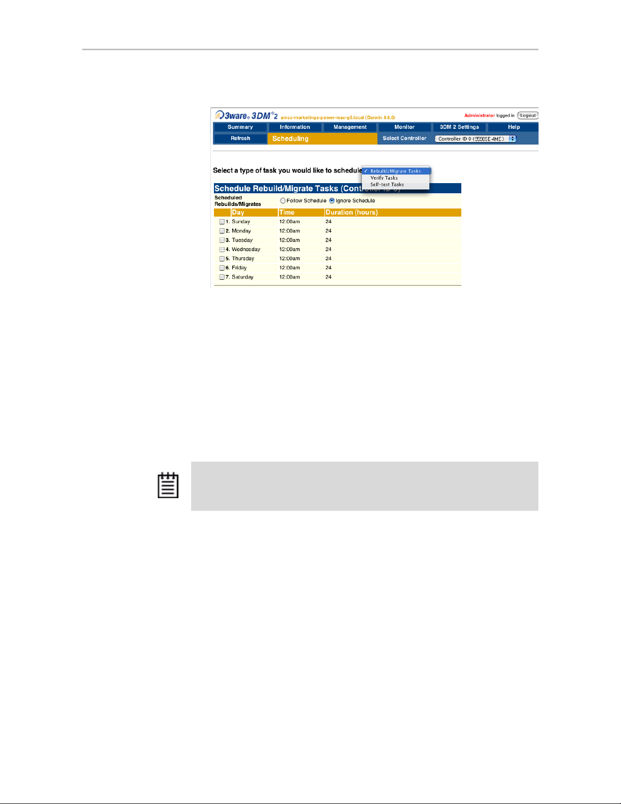
Chapter 6. Maintaining Units
Figure 30. Selecting Task Schedules to View
Turning On or Off Use of a Task Schedule
Turning on the schedule for Rebuild/Migrate and Verify tasks forces rebuilds,
migrates, and verifies to be performed only during the time specified by the
schedule. If the schedule is not turned on, rebuilds, migration, initialization,
and verify can happen whenever they are required or are manually started.
There may be times when you want to disable scheduled rebuild/migrate or
verify tasks, so that you can rebuild, migrate, or verify a unit right away,
without waiting for the next scheduled time. In this case, you can disable the
schedule, as described below.
Note: When you first use 3DM, daily schedules exist with 24 hour duration—that is,
the schedule is for “all the time.” Until you change these 24-hour daily schedule,
enabling the schedule will not have any direct effect.
You can easily disable a current Verify or Rebuild/Migrate schedule without
deleting the schedule itself.
To turn on or off use of the current Verify or Rebuild task
schedule
1 Choose
Management > Schedule from the menu bar.
The Scheduling page appears, showing the schedule for Rebuild/Migrate
Tasks.
2 To view Verify Tasks, select it from the drop-down list at the top of the
page.
78 3war e Ser ial AT A RAID Con tr oller User Guide for Mac OS X
Page 87

3 In the Schedule Rebuild Tasks section, select the appropriate setting:
Follow Schedule or Ignore Schedule.
The illustration below shows this setting for the rebuild task schedule.
Note: Self-test schedules cannot be turned off in this way. To disable self-tests you
must either remove all schedule times, or uncheck the tests listed in the
column. For more information, see “Selecting Self-tests to be Performed” on
page 80
.
Removing a Task Schedule
By default, daily task schedules are defined, each starting at 12:00 am and
running for 24 hours.
Scheduling Background Tasks
Tasks
A maximum of seven schedules can be defined. When seven schedules are
shown for any of the tasks, you must remove a schedule before you can add
another.
To remove a task schedule
1 Choose
Management > Schedule from the menu bar.
The Scheduling page appears, showing the schedule for Rebuild/Migrate
Tasks.
2 To view Verify Tasks or Self-test Tasks, select it from the drop-down list
at the top of the page.
3 Select the checkbox next to the schedule(s) you want to remove.
4 Click the
Remove Checked button.
The page refreshes, and the selected schedule(s) are removed. You can
now add another schedule.
Adding a New Task Schedule Slot
When you add a rebuild/migrate or verify task schedule, you specify the day
of the week, time, and duration for the task. For self-test schedules, you
specify day and time, but not duration. (Duration is not required for self-tests.)
Depending on the schedule and system workload, background tasks may
require more than one scheduled duration to complete.
www.3ware.com 79
Page 88

Chapter 6. Maintaining Units
To add a task schedule slot
1 Choose
Management > Schedule from the menu bar.
The Scheduling page appears, showing the schedule for Rebuild/Migrate
Tasks.
2 To view Verify Tasks or Self-test Tasks, select it from the drop-down list
at the top of the page.
3 Scroll to the section of the Scheduling page that shows the task you want
to add.
4 In the fields at the bottom of the section, select the Day, Time, and
Duration for the task.
5 Click the
Add New Slot button.
The page refreshes and the new schedule is added to the list.
Note: The scheduled tasks can be added in any order . For example a new t ask
scheduled for Tuesday (slot-2) will preempt the task originally scheduled for
Wednesday (slot-1).
Selecting Self-tests to be Performed
Two self-tests can be set: one to check whether UDMA Mode can be
upgraded, and another to check whether SMART thresholds have been
exceeded. (For more information about these self-tests, see the 3DM
Reference section, “Scheduling page” on page 100.)
Initially , these tests are set to run every 24 hours. You can change the schedule
for when they are run, and you can disable the tests, if you prefer not have to
have them performed.
Note: These tasks will only be run during scheduled times if they are checked in
the Schedule Self-tests
checked, self-tests will never run, even if you have scheduled time slots set.
To select self-tests to be performed
1 Choose
Management > Schedule from the menu bar.
The Scheduling page appears, showing the schedule for Rebuild Tasks.
2 Select Self-test Tasks from the drop-down list at the top of the page.
section of the Scheduling page. If neither of the tasks is
80 3war e Ser ial AT A RAID Con tr oller User Guide for Mac OS X
Page 89

Locating a Drive by Blinking Its LED
3 Check the boxes next to the self-tests you want to be performed.
To disable self-tests
Unlike scheduling of rebuilds and verifies, scheduling of self-tests is always
enabled.
To disable self-tests you must either remove all schedule times, or uncheck
the tests listed in the
Tasks column.
Locating a Drive by Blinking Its LED
You can easily identify the drives in a unit, or an individual drive, by causing
the LEDs associated with the drives to blink.
You can issue the command to blink the LED through 3DM.
(For details about what the different LED patterns on the enclosure mean, see
“Enclosure LED Status Indicators” on page 63.)
To blink the LED for a drive
1 Do one of the following:
• Choose
Information > Drive Information from the main menu in
3DM. On the Drive Information page, identify the drive you want to
physically locate.
• Choose
Monitor > Enclosure from the main menu in 3DM. On the
list of enclosures, click the ID number of the enclosure. On the
Enclosure Detail page, identify the drive you want to physically
locate.
2 Check the box in the
Identify column.
The LED on the enclosure begins blinking.
3 When you are finished working with the drive and no longer need to see
the LED, return to this page and uncheck the
Identify box.
www.3ware.com 81
Page 90

Chapter 6. Maintaining Units
To blink the LEDs for all drives in a unit
1 Choose from the main menu in 3DM.
2 On the list of units, locate the unit you want to identify.
3 Check the box in the
Identify column.
The LEDs associated with each drive in the unit begin blinking on the
enclosure.
82 3war e Ser ial AT A RAID Con tr oller User Guide for Mac OS X
Page 91

Maintaining Your Controller
This section contains instructions for how to perform tasks that help you
maintain your controller, including:
• Determining the Current Version of Your 3ware Driver
• Updating the Firmware and Driver
• Updating the Firmware Through 3DM 2
Determining the Current Version of Your 3ware Driver
7
Figure 31. Controller Summary Page
You can view controller and driver information in several different ways:
• Using 3DM 2 you can see both the driver and firmware versions (see the
“Controller Summary page” on page 89)
• Using the CLI you can see both the driver and firmware versions (see
3ware Serial ATA RAID Controller CLI Guide)
www.3ware.com 83
Page 92

Chapter 7. Maintaining Your Controller
Updating the Firmware and Driver
Note: It is a good idea to back up your data before updating the firmware. Updating
the firmware can render the device driver and/or management tools incompatible. It
is also recommended to have a copy of the current firmware image for rollbacks.
You can download the latest drivers and firmware from the 3ware website, at
http://www.3ware.com/support.
Tip: If you only want to update the firmware, you can do so through 3DM,
after downloading it. For more information, see “Updating the Firmware
Through 3DM 2” on page 85.
To download the driver or firmware
1 On the 3ware website (www.3ware.com), navigate to Service and
Support > Software Downloads.
2 Click
Download Released Software.
3 Select the product and release desired.
4 Select Driver or Firmware (as appropriate) as the item to download.
5 Select the Operating System you are using.
6 Click Next.
7 When details about the download you requested appear, click the link for
the item you want to download.
8 Read and agree to the license agreement that appears.
9 Click Save to save the file to disk.
10 Uncompress the file to extract the driver or firmware files to a local
directory.
(Make note of the absolute path to the local directory.)
To update the driver and firmware under Mac OS X
1 Open a Terminal window.
2Type
sudo tw_update and press Enter .
3 When prompted, enter your administrator password.
The usage for the tw_update command displays.
84 3war e Ser ial AT A RAID Con tr oller User Guide for Mac OS X
Page 93

Viewing Battery Information
4Type:
./tw_update fw=[absolute path to the firmware image]
And press Enter.
After the “fw=”, be sure to enter the absolute path to the location of the
firmware image. Do not type the brackets shown in the example above.
5 After the update has completed, power cycle your computer (that is, turn
it off and then turn it on again).
Updating the Firmware Through 3DM 2
You can use 3DM 2 to update the 3ware RAID controller firmware.
To update the firmware through 3DM
1 Download the firmware update from the 3ware website. For details, see
“To download the driver or firmware” on page 84.
2 In 3DM 2, navigate to
3In the
Update Firmware section of Controller Settings page, browse to
Management > Controller Settings.
the location where you have saved the downloaded firmware update.
4 Click
Begin Update.
The 3ware RAID controller firmware is updated.
5 Power cycle your system for the firmware update to take effect.
Viewing Battery Information
The Battery Backup Unit (BBU) is an add-on card that can be attached to
most 3ware 9000 RAID controllers to supply power from a battery pack in the
event of a system power loss. (The BBU is not supported on the 9590SE4ME.) This allows the controller to use write-caching for optimal
performance and to preserve data in the event of a system power failure.
When fully charged, the battery preserves the contents of the cache memory
for up to 72 hours. When power is restored, the cached write data is written to
the disks.
You can see information about a battery backup unit attached to your
controller in both 3DM 2 and 3BM.
www.3ware.com 85
Page 94

Chapter 7. Maintaining Your Controller
Note: When the BBU status is not “Ready,” write caching is automatically disabled
on all units attached to the controller
To view information about a BBU in 3DM 2
• On the menu bar, choose Monitor > Battery Backup.
The Battery Backup page appears, on which you can see details and status
about the unit. This page is refreshed every 30 seconds.
For details about the fields on this page, see “Battery Backup page” on
page 110.
Testing Battery Capacity
Batteries in the BBU need to be replaced periodically. A battery test should be
run every four weeks in order to get a reliable estimate of battery capacity , and
to determine when it needs to be replaced.
The battery test is used to measure the battery’s capacity to back up write data.
In order to make a reliable estimate of battery capacity, the BBU pre-charges
the battery before it proceeds with a full discharge cycle. The battery is
automatically charged again after the test completes. The whole process
usually takes between 8 and 12 hours.
While running the battery test and until charging is completed, write cache is
temporarily disabled.
For how to replace the battery, see the installation guide that came with your
controller.
To test the battery in a BBU in 3DM 2
1 On the menu bar, choose Monitor > Battery Backup.
2 On the Battery Backup page, click the Test Battery Capacity link.
86 3war e Ser ial AT A RAID Con tr oller User Guide for Mac OS X
Page 95

Testing Battery Capacity
Figure 32. Battery Backup Information Screen in 3DM
3 When a message cautions you that testing the battery will disable the
BBU for up to 24 hours, click OK to continue.
After the battery test starts, you will see the voltage start dropping;
eventually the battery voltage will say "LOW". This is part of the battery
test. After the voltage drops to a point, it will start charging again, and the
status will change to “Charging.” Eventually, the battery voltage will say
“OK” again.
Figure 33. BBU Information Screen While Battery is Testing
www.3ware.com 87
Page 96

8
3DM 2 Reference
This section includes details about the fields and features available on the
pages you work with throughout 3DM 2. It is organized by 3DM page, as the
pages are organized on the 3DM menu bar.
• Controller Summary page
• Controller Details page
• Unit Information page
• Unit Details page
• Drive Information page
• Drive Details window
• Controller Settings page
• Scheduling page
• Maintenance page
• Alarms page
• Battery Backup page
• Enclosure Summary page
• Enclosure Details page
• 3DM 2 Settings page
88 3war e Ser ial AT A RAID Con tr oller User Guide for Mac OS X
Page 97

Controller Summary page
Figure 34. Controller Summary Page
The Summary page appears after you first logon to 3DM, and when you click
the Summary link in the menu bar.
This page provides basic information about each 3ware RAID controller in
your system. T o see details about the units in a controller, click the link in the
ID column.
Controller Summary page
ID. The ID that the operating system assigns to the controller.
Model. The model name of the controller. (The model number is also printed
Note: The controller ID you see in 3DM 2 may not match the number that you see
for the same controller in 3DM version 1.x.
on a sticker on the outside bracket of the controller.)
Serial #. The serial number of the controller. (The serial number is also
printed on a sticker on the backside of the controller.)
Firmware. The firmware version running on the controller.
Driver. The driver version being used to interact with the controller.
Status. The overall status of the controller. Possible statuses include OK,
Warning, Error, and No Units.
currently being performed (rebuilding, migrating, or initializing).
Warning indicates that a background task is
Error
indicates that a unit is degraded or inoperable. If both Error and Warning
conditions exist, the status will appear as Error. For more information, see
“Checking Unit and Drive Status” on page 60.
www.3ware.com 89
Page 98

Chapter 8. 3DM 2 Reference
Controller Details page
Figure 35. Controller Details Page
The Controller Details page appears when you choose Information >
Controller Details
from the menu bar.
This page provides detailed information about the controller specified in the
drop-down list on the menu bar.
You can also open or download an error log from this screen.
Model. The model name of the controller.
Serial #. The serial number of the controller.
Firmware. The firmware version running on the controller.
Driver. The driver version being used to interact with the controller.
BIOS. The BIOS version on the controller.
Boot Loader. Boot Loader version on the controller.
Memory Installed. The amount of memory installed on the controller.
Bus T ype. The bus type used on the con troller is shown: PCI, PCIX, or PCIE.
Bus Width. The bu s width used on the co ntroller: 4 lanes, 8 lanes, or 16 lanes
for PCIE slots.
Bus Speed. The speed of the bus used on the controller is shown.
# of Ports. The number of total ports on the controller, regardless of whether
each currently has a drive connected.
# of Units. The number of units on the controller.
90 3war e Ser ial AT A RAID Con tr oller User Guide for Mac OS X
Page 99

# of Drives. The number of drives connected to the controller.
Download Error Log: Click on this link to download the firmware error log
to your computer. This feature is important when contacting AMCC for
support with your controller. It will help AMCC identify the problem you
encountered.
Unit Information page
Figure 36. Unit Information Page
Unit Information page
The Unit Information page appears when you choose Information > Unit
Information
from the menu bar, or when you click an ID number on the
Controller Summary page.
This page shows a list of the units on the current controller and provides
summary information about each unit.
To see details about a particular unit, click the link in the Unit # column.
Unit #. The unit number assigned to the unit by the firmware.
Name. If a name has been given to this unit, it shows here. If it is empty, no
name has been assigned. You can name your unit in the
of the
Management > Controller Settings page.
Type. The type of unit, specified during configuration: RAID 0, RAID 1,
Unit Names section
RAID 5, RAID 10, Single Disk, or Spare. For details about each of the RAID
levels, see “Available RAID Configurations” on page 7.
Capacity. The logical capacity (size) of the unit. 1KB = 1024 bytes.
Status. The operational status of the unit: OK, Rebuilding, Initializing,
Migrating, Verifying, Degraded, or Inoperable (missing drives). When a unit
is Rebuilding, Initializing, Migrating, or Verifying, the percentage (%)
complete is also shown. For an explanation of the statuses, see “Unit Statuses”
on page 63.
www.3ware.com 91
Page 100

Chapter 8. 3DM 2 Reference
Note: If an asterisk (*) appears next to the status of a unit, there is an error on one
of the drives in the unit. This feature provides a diagnostic capability for potential
problem drives. The error may not be a repeated error, and may be caused by an
ECC error, SMART failure, or a device error. To see if this error condition still exists,
rescan the controller; rescanning will clear the drive error status if the condition no
longer exists.
Identify. Check this box to cause the LED for the drives associated with this
unit to blink in the enclosure. .
Unit Details page
Figure 37. Unit Details Page
The Unit Details page appears when you click an ID number on the Unit
Information page. Because it is a sub-page of Unit Information, the page title
in the menu bar continues to display “Unit Information” even when you view
details of a unit.
The Unit Details page shows details about a particular unit. The specific
information shown depends on what type of unit it is. For example, details
about a RAID 5 unit made up of three subunits, each of which contains one
drive, will include details about the unit and each subunit, as shown in
Figure 37. However, if the unit is a Single Disk, only information about one
disk will be shown.
Details on this page may include all or some of the following information
described below .
92 3war e Ser ial AT A RAID Con tr oller User Guide for Mac OS X
 Loading...