

Page 1
TM
Escalade
Storage Switch
Supports the 6000 and 7000 series
PN 720-0034-02, Revision C
March 8, 2002
Page 2

Copyright
©2002 3ware, Inc. All rights reserved. No part of this publication may be
reproduced, stored in a retrieval system, or transmitted in any form by any
means, electronic, mechanical, photocopying, recording or otherwise,
without the proper written consent of 3ware, Inc., 701 East Middlefield
Road, Suite 300, Mountain View CA 94043.
Trademarks
3ware, the 3ware logo, Palisade, Escalade, StorSwitch, TwinStor, R5
Fusion and 3DM are all registered trademarks of 3ware, Inc. All other
trademarks herein are property of their respective owners.
Disclaimer
3ware, Inc. assumes no responsibility for errors or omissions in this document, nor does 3ware, Inc. make any commitment to update the information conta i ned herein.
Page 3

Contents
Before You Begin . . . . . . . . . . . . . . . . . . . . . . . . . . . . . . . . . . . . 1
Features . . . . . . . . . . . . . . . . . . . . . . . . . . . . . . . . . . . . . . . . . . . .1
Escalade 6000 Family (includes 6800, 6400, 6410, 6200) . . .1
Escalade 7000 Family (includes 7210, 7810, 7410, 7850,
7450) . . . . . . . . . . . . . . . . . . . . . . . . . . . . . . . . . . . . . . . . . . . .2
Package contents . . . . . . . . . . . . . . . . . . . . . . . . . . . . . . . . . . . . .2
Tools required . . . . . . . . . . . . . . . . . . . . . . . . . . . . . . . . . . . . . . .3
System requirements . . . . . . . . . . . . . . . . . . . . . . . . . . . . . . . . . .3
Personal safety . . . . . . . . . . . . . . . . . . . . . . . . . . . . . . . . . . . . . .3
Protecting equipment and data . . . . . . . . . . . . . . . . . . . . . . . . . .4
ESD precautions . . . . . . . . . . . . . . . . . . . . . . . . . . . . . . . . . . . . .4
Mechanical concerns . . . . . . . . . . . . . . . . . . . . . . . . . . . . . . . . . .4
Introduction . . . . . . . . . . . . . . . . . . . . . . . . . . . . . . . . . . . . . . . . . 7
Quick Installation Guide . . . . . . . . . . . . . . . . . . . . . . . . . . . . . . 13
Step 1. Install the Escalade Storage Switch . . . . . . . . . . . . . . . 1 4
Step 2. Create Arrays . . . . . . . . . . . . . . . . . . . . . . . . . . . . . . . .14
Step 3. Install System Drivers . . . . . . . . . . . . . . . . . . . . . . . . . .14
Step 4. RAID Array Background Initialization Process . . . . . .15
Step 5. Install 3DM . . . . . . . . . . . . . . . . . . . . . . . . . . . . . . . . . .15
Hardware Installation . . . . . . . . . . . . . . . . . . . . . . . . . . . . . . . . 17
To remove an existing Escalade Storage Switch . . . . . . . . . . .18
Connect the interface cables to the Escalade Storage Switch . .18
Install the Escalade Storage Switch in the computer . . . . . . . .19
Connect the drives to the interface cables . . . . . . . . . . . . . . . .20
Check your installation and close the case . . . . . . . . . . . . . . . .20
Check motherboard boot sequence . . . . . . . . . . . . . . . . . . . . . .21
3ware Disk Array Configuration Utility . . . . . . . . . . . . . . . . . . 23
Hot Spare and Hot Swap . . . . . . . . . . . . . . . . . . . . . . . . . . . . . .23
BIOS Screen . . . . . . . . . . . . . . . . . . . . . . . . . . . . . . . . . . . . .23
3DM Configure Page . . . . . . . . . . . . . . . . . . . . . . . . . . . . . . .24
Invoking the 3ware BIOS tool . . . . . . . . . . . . . . . . . . . . . . . . .24
Exiting the 3ware BIOS tool . . . . . . . . . . . . . . . . . . . . . . . . . . .25
Determining your configuration . . . . . . . . . . . . . . . . . . . . . . . .26
Displaying advance details . . . . . . . . . . . . . . . . . . . . . . . . . . . .2 7
Creating a disk array . . . . . . . . . . . . . . . . . . . . . . . . . . . . . . . . .28
Determining your configuration . . . . . . . . . . . . . . . . . . . . . . . .29
iii
Page 4

3ware Esca lade Storage Switch User Guide
Specifying a hot spare . . . . . . . . . . . . . . . . . . . . . . . . . . . . . . . 34
Changing an existing configuration . . . . . . . . . . . . . . . . . . . . . 34
Modifying a disk array . . . . . . . . . . . . . . . . . . . . . . . . . . . . . . . 34
Deleting a disk array . . . . . . . . . . . . . . . . . . . . . . . . . . . . . . . . 35
How to maintain or verify a disk array . . . . . . . . . . . . . . . . . . 36
Rebuilding a mirrored disk array . . . . . . . . . . . . . . . . . . . . . . . 37
Rebuilding a RAID 5 disk array . . . . . . . . . . . . . . . . . . . . . . . 39
Windows Installation . . . . . . . . . . . . . . . . . . . . . . . . . . . . . . . . 45
Windows NT®4.0 Installation . . . . . . . . . . . . . . . . . . . . . . . . . 46
Adding drives to an existing storage switch . . . . . . . . . . . . . . 47
Boot the machine . . . . . . . . . . . . . . . . . . . . . . . . . . . . . . . . . 47
Installing the storage switch and Windows NT 4.0 . . . . . . . . . 48
Create disk arrays . . . . . . . . . . . . . . . . . . . . . . . . . . . . . . . . . 48
Has your boot drive been partitioned? . . . . . . . . . . . . . . . . . 48
Boot the system . . . . . . . . . . . . . . . . . . . . . . . . . . . . . . . . . . . 48
Continue with Windows NT 4.0 installation . . . . . . . . . . . . 49
Install the driver using the 3ware diskette . . . . . . . . . . . . . . 49
Partition device 0 to create a boot area . . . . . . . . . . . . . . . . . 49
Follow display instructions to complete Windows NT 4.0
installation . . . . . . . . . . . . . . . . . . . . . . . . . . . . . . . . . . . . . . . 50
RAID array initialization . . . . . . . . . . . . . . . . . . . . . . . . . . . 51
Install the 3DM disk management utility . . . . . . . . . . . . . . . 51
Installing the storage switch on systems that boot from a
different device . . . . . . . . . . . . . . . . . . . . . . . . . . . . . . . . . . . . 52
Create disk arrays . . . . . . . . . . . . . . . . . . . . . . . . . . . . . . . . . 52
Install the 3ware driver . . . . . . . . . . . . . . . . . . . . . . . . . . . . . 52
Reboot the machine . . . . . . . . . . . . . . . . . . . . . . . . . . . . . . . . 52
RAID array initialization . . . . . . . . . . . . . . . . . . . . . . . . . . . 53
Install the 3DM disk management utility . . . . . . . . . . . . . . . 53
Replacing an existing storage swi t ch with a new version of the
switch . . . . . . . . . . . . . . . . . . . . . . . . . . . . . . . . . . . . . . . . . . . . 54
Update the 3ware driver . . . . . . . . . . . . . . . . . . . . . . . . . . . . 54
Install/Update the 3ware driver . . . . . . . . . . . . . . . . . . . . . . . 55
Remove the existing Escalade Storage Switch and install the
new Escalade Storage Switch . . . . . . . . . . . . . . . . . . . . . . . . 58
Reboot the machine . . . . . . . . . . . . . . . . . . . . . . . . . . . . . . . . 58
iv
Page 5

RAID array initialization . . . . . . . . . . . . . . . . . . . . . . . . . . . .59
Install the 3DM disk management utility . . . . . . . . . . . . . . .59
Windows® 98/ME Installation . . . . . . . . . . . . . . . . . . . . . . . . . 60
Adding a drive to an existing storage switch . . . . . . . . . . . . . . 62
Partition and format new drive . . . . . . . . . . . . . . . . . . . . . . .62
Installing the storage switch while installing Windows 98/ME 63
Create disk arrays . . . . . . . . . . . . . . . . . . . . . . . . . . . . . . . . .63
Boot the system from the Windows 98/ME diskette . . . . . . .63
Partition the boot device using fdisk . . . . . . . . . . . . . . . . . . .63
Restart the machine and format the boot device . . . . . . . . . .64
Continue the standard Windows 98/ME installation . . . . . . .64
Partition and format other devices . . . . . . . . . . . . . . . . . . . . .6 5
RAID array initialization . . . . . . . . . . . . . . . . . . . . . . . . . . . .65
Install the 3DM Disk Management Utility. . . . . . . . . . . . . . .65
Installing the storage switch on systems that boot from a
different device . . . . . . . . . . . . . . . . . . . . . . . . . . . . . . . . . . . . .66
Create disk arrays . . . . . . . . . . . . . . . . . . . . . . . . . . . . . . . . .66
Install the 3ware driver . . . . . . . . . . . . . . . . . . . . . . . . . . . . . 6 6
Partition and format units on storage switch . . . . . . . . . . . . .67
RAID array initialization . . . . . . . . . . . . . . . . . . . . . . . . . . . .68
Install the 3DM disk management utility . . . . . . . . . . . . . . .68
Replacing an existing storage swi t ch with a new version of the
switch . . . . . . . . . . . . . . . . . . . . . . . . . . . . . . . . . . . . . . . . . . . .69
Update the 3ware driver . . . . . . . . . . . . . . . . . . . . . . . . . . . . .69
Install/Update the 3ware driver . . . . . . . . . . . . . . . . . . . . . . .71
Remove the existing Escalade Storage Switch and install the
new Escalade Storage Switch . . . . . . . . . . . . . . . . . . . . . . . .75
Reboot the machine . . . . . . . . . . . . . . . . . . . . . . . . . . . . . . . .75
Windows® 2000 or Windows XP Installation . . . . . . . . . . . . . 76
Installing a drive to an existing storage switch . . . . . . . . . . . . .78
Boot the machine . . . . . . . . . . . . . . . . . . . . . . . . . . . . . . . . . .78
Installing the storage switch while installing Windows 2000 or
Windows XP . . . . . . . . . . . . . . . . . . . . . . . . . . . . . . . . . . . . . . .79
Create disk arrays . . . . . . . . . . . . . . . . . . . . . . . . . . . . . . . . .79
Installing with the Initial Operating System Build . . . . . . . .79
Continue with Windows 2000 or XP installation . . . . . . . . .79
v
Page 6

3ware Esca lade Storage Switch User Guide
Reboot the machine . . . . . . . . . . . . . . . . . . . . . . . . . . . . . . . . 80
RAID array initialization . . . . . . . . . . . . . . . . . . . . . . . . . . . 81
Install the 3DM disk management utility . . . . . . . . . . . . . . . 81
Installing the storage switch on systems that boot from a
different device . . . . . . . . . . . . . . . . . . . . . . . . . . . . . . . . . . . . 82
Create disk arrays . . . . . . . . . . . . . . . . . . . . . . . . . . . . . . . . . 82
Install the 3ware driver . . . . . . . . . . . . . . . . . . . . . . . . . . . . . 82
Reboot the machine . . . . . . . . . . . . . . . . . . . . . . . . . . . . . . . . 83
RAID array initialization . . . . . . . . . . . . . . . . . . . . . . . . . . . 84
Install the 3DM disk management utility . . . . . . . . . . . . . . . 84
Replacing an existing storage swi t ch with a new version of the
switch . . . . . . . . . . . . . . . . . . . . . . . . . . . . . . . . . . . . . . . . . . . . 85
Updating the 3ware driver . . . . . . . . . . . . . . . . . . . . . . . . . . 85
Installing/Updating the 3ware driver . . . . . . . . . . . . . . . . . . 88
Remove the existing Escalade Storage Switch and install the
new Escalade Storage Switch . . . . . . . . . . . . . . . . . . . . . . . . 94
Reboot the machine . . . . . . . . . . . . . . . . . . . . . . . . . . . . . . . . 94
RAID array initialization . . . . . . . . . . . . . . . . . . . . . . . . . . . 95
Install the 3DM disk management utility . . . . . . . . . . . . . . . 95
Linux Installation . . . . . . . . . . . . . . . . . . . . . . . . . . . . . . . . . . . 97
Red Hat® Linux Installation . . . . . . . . . . . . . . . . . . . . . . . . . . 98
Installing the storage switch while installing Red Hat Linux . 99
Create disk arrays . . . . . . . . . . . . . . . . . . . . . . . . . . . . . . . . . 99
Boot with the Red Hat CD-ROM or diskette . . . . . . . . . . . . 99
Install the driver . . . . . . . . . . . . . . . . . . . . . . . . . . . . . . . . . 100
Complete the normal Red Hat installation . . . . . . . . . . . . . 101
RAID array initialization . . . . . . . . . . . . . . . . . . . . . . . . . . 101
Install and run 3DM disk management utility . . . . . . . . . . 101
Installing the storage switch on systems that boot from a
different device . . . . . . . . . . . . . . . . . . . . . . . . . . . . . . . . . . . 102
Create disk arrays . . . . . . . . . . . . . . . . . . . . . . . . . . . . . . . . 102
Install the 3ware driver . . . . . . . . . . . . . . . . . . . . . . . . . . . . 102
RAID array initialization . . . . . . . . . . . . . . . . . . . . . . . . . . 106
Install and run 3DM disk management utility . . . . . . . . . . 106
SuSE® Linux Installation . . . . . . . . . . . . . . . . . . . . . . . . . . . . 107
Installing the storage switch while installing SuSE Linux w ith
vi
Page 7

YaST1 . . . . . . . . . . . . . . . . . . . . . . . . . . . . . . . . . . . . . . . . . . .108
Materials required . . . . . . . . . . . . . . . . . . . . . . . . . . . . . . . .108
Create disk arrays . . . . . . . . . . . . . . . . . . . . . . . . . . . . . . . .108
Boot with the SuSE CD/DVD or diskette . . . . . . . . . . . . . .108
Install the driver via a command shell . . . . . . . . . . . . . . . . .109
Set up the system so driver will load on boot . . . . . . . . . . .110
Edit the lilo.conf file . . . . . . . . . . . . . . . . . . . . . . . . . . . . . .110
RAID array initialization . . . . . . . . . . . . . . . . . . . . . . . . . . .111
Install and run 3DM disk management utility . . . . . . . . . . .111
Installing the storage switch on systems that boot from a
different device . . . . . . . . . . . . . . . . . . . . . . . . . . . . . . . . . . . .112
Create disk arrays . . . . . . . . . . . . . . . . . . . . . . . . . . . . . . . .112
Install the 3ware driver . . . . . . . . . . . . . . . . . . . . . . . . . . . .112
RAID array initialization . . . . . . . . . . . . . . . . . . . . . . . . . . .114
Install and run 3DM disk management utility . . . . . . . . . . .115
3DM Disk Management Utility . . . . . . . . . . . . . . . . . . . . . . . . 117
Windows Installation . . . . . . . . . . . . . . . . . . . . . . . . . . . . . . . 118
Installing 3DM for Windows NT, Windows 98/ME, Windows
2000, Windows XP . . . . . . . . . . . . . . . . . . . . . . . . . . . . . . . . .118
Linux Installation . . . . . . . . . . . . . . . . . . . . . . . . . . . . . . . . . . 121
Installing 3DM for Red Hat Linux or SuSE Linux . . . . . . . .121
Starting 3DM . . . . . . . . . . . . . . . . . . . . . . . . . . . . . . . . . . . . .123
Uninstalling 3DM . . . . . . . . . . . . . . . . . . . . . . . . . . . . . . . . . . 123
Checking Array Status . . . . . . . . . . . . . . . . . . . . . . . . . . . . . . 125
View status using your standard browser . . . . . . . . . . . . . . . .125
Password Setup . . . . . . . . . . . . . . . . . . . . . . . . . . . . . . . . . . . . 131
Enable/Disable Password Protection . . . . . . . . . . . . . . . . . . .133
Selecting Rebuild Rate . . . . . . . . . . . . . . . . . . . . . . . . . . . . . .134
Selecting Cache Options . . . . . . . . . . . . . . . . . . . . . . . . . . . . .134
Event notification via e-mail . . . . . . . . . . . . . . . . . . . . . . . . . . 134
Mirrored Array Maintenance . . . . . . . . . . . . . . . . . . . . . . . . . 135
Specifying a hot spare . . . . . . . . . . . . . . . . . . . . . . . . . . . . . . .137
Auto rebuild of a mirrored array . . . . . . . . . . . . . . . . . . . . .137
Rebuilding a redundant array with a hot swap drive . . . . . . . 137
Selecting Force Continue . . . . . . . . . . . . . . . . . . . . . . . . . . .138
Scheduling rebuilds and media scans . . . . . . . . . . . . . . . . . . .138
vii
Page 8

3ware Esca lade Storage Switch User Guide
Troubleshooting: Problems and Solutions . . . . . . . . . . . . . 141
Hardware Installation . . . . . . . . . . . . . . . . . . . . . . . . . . . . . . . 141
Software Installation . . . . . . . . . . . . . . . . . . . . . . . . . . . . . . . 142
Screen Display Messages . . . . . . . . . . . . . . . . . . . . . . . . . . . . 145
AEN Messages . . . . . . . . . . . . . . . . . . . . . . . . . . . . . . . . . . 148
Appendix A
Compliance and Conformity Statements . . . . . . . . . . . . . . . 157
Federal Communications Commission Radio Frequency Interfer-
ence Statement . . . . . . . . . . . . . . . . . . . . . . . . . . . . . . . . . . . . 157
Microsoft Windows Hardware Quality Lab (WHQL) . . . . . . 158
European Community Conformity Statement . . . . . . . . . . . . 158
Appendix B
Warranty, Technical Support and Service . . . . . . . . . . . . . . 159
Limited Warranty . . . . . . . . . . . . . . . . . . . . . . . . . . . . . . . . . . 159
Exclusions . . . . . . . . . . . . . . . . . . . . . . . . . . . . . . . . . . . . . . . 159
State Law Provisions . . . . . . . . . . . . . . . . . . . . . . . . . . . . . . . 160
Obtaining Warranty Protection . . . . . . . . . . . . . . . . . . . . . . . 160
3ware Technical Support and Services . . . . . . . . . . . . . . . . . 160
Sales and ordering information . . . . . . . . . . . . . . . . . . . . . . . 161
Feedback on this manual . . . . . . . . . . . . . . . . . . . . . . . . . . . . 161
viii
Page 9

List of Figures
Figure 1. RAID 0 Configuration Example 8
Figure 2. RAID 1 Configuration Example . . . . . . . . . . . . . . . . . 8
Figure 3. RAID 10 Configuration Example . . . . . . . . . . . . . . . . 9
Figure 4. RAID 5 Configuration Example . . . . . . . . . . . . . . . . 10
Figure 5. 8-Port Escalade 7850 Storage Switch Layout . . . . . .17
Figure 6. 3ware BIOS Tool . . . . . . . . . . . . . . . . . . . . . . . . . . .25
Figure 7. Disk Array Configuration Main Display, RAID 1
Example 27
Figure 8. Disk Array Advance Details Screen . . . . . . . . . . . . .28
Figure 9. Selecting Drives for a Mirrored Array . . . . . . . . . . . 29
Figure 10. Create Disk Array Display, RAID 0 Example . . . . . 30
Figure 11. Create Disk Array Display, RAID 5 Example . . . . . 31
Figure 12. BIOS Initialization Screen for RAID 5 . . . . . . . . . . 32
Figure 13. Delete Disk Array Display . . . . . . . . . . . . . . . . . . . .35
Figure 14. Maintain Disk Array Display . . . . . . . . . . . . . . . . . .36
Figure 15. Degraded RAID 1 Array Drive When Not in Use . . 37
Figure 16. Degraded RAID 10 Array Drive When Not in Use . 38
Figure 17. Degraded RAID 5 Array Drive When Not in Use . . 39
Figure 18. Select Available Drive to Replace Faulted Drive,
RAID 1 Example . . . . . . . . . . . . . . . . . . . . . . . . . . . . 41
Figure 19. Rebuild Array Status Display, RAID 1 Example . . . 42
Figure 20. Rebuild Confirmation Display . . . . . . . . . . . . . . . . . 43
Figure 21. Storage Switch Quick-Splash Screen . . . . . . . . . . . .50
Figure 22. Installation Complete Notification . . . . . . . . . . . . . .50
Figure 23. Remove Current Driver . . . . . . . . . . . . . . . . . . . . . . . 5 5
Figure 24. Install Driver . . . . . . . . . . . . . . . . . . . . . . . . . . . . . . . 56
Figure 25. Install from Disk . . . . . . . . . . . . . . . . . . . . . . . . . . . .57
Figure 26. Install Driver . . . . . . . . . . . . . . . . . . . . . . . . . . . . . . . 58
Figure 27. Add New Hardware Wizard . . . . . . . . . . . . . . . . . . .67
Figure 28. 3ware Storage Switch Properties Display . . . . . . . . . 70
Figure 29. Install Hardware Device Drivers . . . . . . . . . . . . . . . 71
Figure 30. Select a Device Driver Display . . . . . . . . . . . . . . . . .72
Figure 31. Install from Disk . . . . . . . . . . . . . . . . . . . . . . . . . . . .73
Figure 32. Update driver . . . . . . . . . . . . . . . . . . . . . . . . . . . . . .73
Figure 33. Final driver installation screen . . . . . . . . . . . . . . . . . 74
Figure 34. Storage Switch Quick-Splash Screen . . . . . . . . . . . .74
ix
Page 10

3ware Esca lade Storage Switch User Guide
Figure 35. Installation Complete Notification . . . . . . . . . . . . . . 75
Figure 36. Storage Switch Quick-Splash Screen . . . . . . . . . . . . 80
Figure 37. Installation Complete Notification. . . . . . . . . . . . . . 80
Figure 38. Found New Hardware Wizard. . . . . . . . . . . . . . . . . . 83
Figure 39. 3ware Storage Switch Properties Display . . . . . . . . 86
Figure 40. Upgrade driver welcome screen . . . . . . . . . . . . . . . . 87
Figure 41. Update/Install device driver . . . . . . . . . . . . . . . . . . 88
Figure 42. Select a Device Driver . . . . . . . . . . . . . . . . . . . . . . . 89
Figure 43. Install From Disk . . . . . . . . . . . . . . . . . . . . . . . . . . . 90
Figure 44. Select a Device Driver . . . . . . . . . . . . . . . . . . . . . . . 91
Figure 45. Start Device Driver Installation . . . . . . . . . . . . . . . . 92
Figure 46. Digital Signature Not Found . . . . . . . . . . . . . . . . . . 93
Figure 47. Final driver installation screen . . . . . . . . . . . . . . . . . 94
Figure 48. 3DM Remote Monitoring Configuration Display . 119
Figure 49. 3DM E-mail Notification Preferences . . . . . . . . . . 120
Figure 50. 3DM Home Display . . . . . . . . . . . . . . . . . . . . . . . . 127
Figure 51. 3DM Details Display . . . . . . . . . . . . . . . . . . . . . . . 128
Figure 52. 3DM Monitor Display . . . . . . . . . . . . . . . . . . . . . . 129
Figure 53. 3DM Alarm Display . . . . . . . . . . . . . . . . . . . . . . . . 130
Figure 54. 3DM Settings Display . . . . . . . . . . . . . . . . . . . . . . 131
Figure 55. 3DM Login Display . . . . . . . . . . . . . . . . . . . . . . . . 133
Figure 56. 3DM Configure Display . . . . . . . . . . . . . . . . . . . . 136
Figure 57. 3DM Help Display . . . . . . . . . . . . . . . . . . . . . . . . . 139
Figure 58. Installation or Removal Dialog Box . . . . . . . . . . . . 146
Figure 59. A Warning for All Software Removal Requests . . 146
Figure 60. Confirmation of Successful Software Removal . . . 146
Figure 61. Administrator Privileges Required Warning . . . . . 147
Figure 62. Firmware Upgrade Requirement Warning . . . . . . . 147
Figure 63. System Reboot Request . . . . . . . . . . . . . . . . . . . . . 147
x
Page 11

Before you Begin
Before You Begin
Congratulations on sel ecting th e Escalade S torage Swi tch as your
RAID data storage and management system. This user guide
gives simple, step-by-st ep instructio ns for instal ling and confi guring your Escalade S torage Swit ch. To ensure your personal safety
and protect your equipment and data, carefully read the information that follows the Features list before you begin installing.
Features
Escalade 6000 Family (includes 6800, 6400, 6410, 6200)
• True Hardware RAID. Low CPU utilization
• RAID Support. RAID 0, 1, 5, 10 and JBOD
• Bus Type. PCI 32 bit / 33 Mhz
• Management. 3DM Disk Management Utility and e -mai l event
notification
• BIOS. PC99, PnP, BBS Compliant
• Windows Support. W98, WME, WinNT, Win2k, WinXP
• Linux Support. Redhat, SuSE. (Drivers available in Open
Source.)
• Performance. Twinstor, Command Queuing, Elevator Seeking,
Ultra DMA66
• Field Upgrades. Field Upgradea bl e F ir mware, BIOS, 3DM and
Drivers
• Data Integrity. A TA Command Readback, SMART Monitor-
ing, Dynamic Sector Repair, Rebuild Pacing, Rebuild Scheduling, Background Scrubbing, Scheduled Scrubbing, Hot Swap,
Hot Spare, Hardware Health Monitoring
www.3ware.com 1
Page 12

3ware Esca lade Storage Switch User Guide
Escalade 7000 Family (includes 7210, 7810, 7410, 7850,
7450)
• True Hardware RAID. Low CPU Utilization
• RAID Support. RAID 0, 1, 5, 10 and JBOD
• Bus Type. PCI 64 bit / 33 Mhz
• Management. 3DM Disk Management Utility
• BIOS. PC99, PnP, BBS Compliant
• Windows Support. W98, WME, WinNT, Win2k, WinXP
• Linux Support. Redhat, SuSE . (Drivers available in Open
Source.)
• Performance. Twinstor, Command Queuing, Elevator Seeking,
R5Fusion, UltraDMA100
• Field Upgrades. Field Upgradea bl e F ir mware, BIOS, 3DM and
Drivers
• Data Integrity . AT A Command Readback, SMAR T Monitor ing,
Dynamic Sector Repair, Rebuild Pacing, Rebuild Scheduling,
Background Scrubbing, Scheduled Scrubbing, Hot Swap, Hot
Spare, Hardware Health Monitoring
Package contents
If your package is missing any of the items listed below, contact
3ware before proceeding with installation (disk drives and disk
mounting brackets are not included):
• Escalade Storage Switch in an ESD-protective bag
• 3ware driver installation media
• 3ware 3DM installation media
• ATA interface cables (one per port)
• Y-splitter cables for connecting additional drives to the power
source (not provided for 2-port models)
• Escalade Installation Guide and Escalade User Guide (.pdf format)
2 www.3ware.com
Page 13
Before you Begin
Tools required
• An ESD grounding strap or mat
• Standard hand tools to open your system’s case and install the
Escalade Storage Switch into an available PCI expansion slot.
System requirements
The Escalade Storage Switch requires a workstation-class or
server-class CPU whose bus complies with PCI 2.1 standards,
and a PCI slot that meets the Plug and Play
and PC99 specifications. The storage switch requires one full-size PCI-bus slot. It
may be connected to up to two, four or eight IDE/ATA drives by
the supplied 40-pin, 80-conductor ribbon interface cables.
Note: The blue end of the ri bbon i nterface cable pl ugs into
the Escalade Storage Switch and the black end plugs into
the drive.
Drives must meet UltraATA-100, UltraATA-66 or UltraATA-33
standards, but may be of any capacity or physical form factor.
Length of unshielded interface cables may not exceed 18” (45.7
cm).
Personal safety
Warning! High voltages may be found inside computer
equipment. Before installing any of the hardware in this
package or removing the protective covers of any computer equipment, turn of f power swit ches and discon nect
power cords. Do not reconn ect the power cor ds until you
have replaced the covers.
www.3ware.com 3
Page 14

3ware Esca lade Storage Switch User Guide
Protecting equipment and data
Back up your data! Creating or deleting disk arrays
destroys existing files on the member drives. If your
drives contain val uable dat a, back t hem up and save data
elsewhere before changing your array configuration.
ESD precautions
Standard electrostatic discharge (ESD) precautions must be followed to avoid damaging computer components and accessories
when installing or removing the Escalade Storage Switch.
• When the case of your comput er is op en and it s inter nal part s are
exposed, don’t touch any internal part unnecessarily.
• Always wear a grounded strap or work on an ESD-protective
mat.
• Don’t remove the storage switch from its protective bag until
you are properly grounded.
• Handle the storage switch by its edges or by the black rail and
metal bracket at its two ends.
• Don’t touch any pin, contact, lead or component on the storage
switch.
Mechanical concerns
Be careful when installing the Escalade Storage Sw itch into your
system. Excessive force can damage the board, the cables, your
drives or your system.
• Be sure the board is aligned with its slot on the motherboard
before installing. Do not flex the board excessively.
• Interface cable connectors must be mated carefully without
bending any pins. The connectors provided a re keyed to prevent
you from inserting them upside-down.
4 www.3ware.com
Page 15

• The blue end of the interface cable plugs into the board and the
black end plugs into the drive.
• Interface cables are fragile and must not be crimped or pinched.
Ensure that they do not impe de the f low of cooli ng air f rom fans
or heat sinks in the system case.
5
Page 16

3ware Esca lade Storage Switch User Guide
6 www.3ware.com
Page 17

Introduction
Introduction
Escalade Storage Switches allow you to use low-cost IDE/ATA
drives in your storage system and still achieve performance levels
and fault tolerance capabilities typically found in more expensive
SCSI systems. Escalade S torage Switc hes are avai lable as two, four
or eight port configura tions, as well as a shortened four or eight port
versions designed for higher density rack-mounted applications.
StorSwitch architecture for scalable performance
The StorSwitch Architecture, found only in 3ware products, accelerates your storage sys tem’s performance by speeding data into system memory. Each drive has its own dedicated AccelerATA data
IDE port, maximizing drive and system throughput.
RAID increases performance and adds redundancy
Escalade Storage Switches use Redundant Array of Inexpensive
Disks (RAID) to increase your storage system’s performance and
provide fault tol eranc e. The s torag e sw itche s of fe r RAID 0 varia ble
striped arrays for performance; RAID 1 mirrored arrays for fault
tolerance; variable striped mirrored RAID 10 arrays for fault tolerance and performance; and RAID 5 arrays for fault tolerance, high
capacity an d storage efficiency.
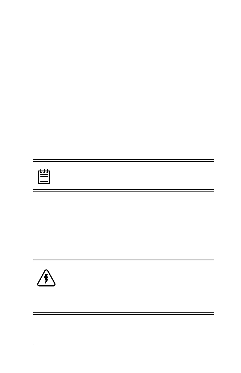
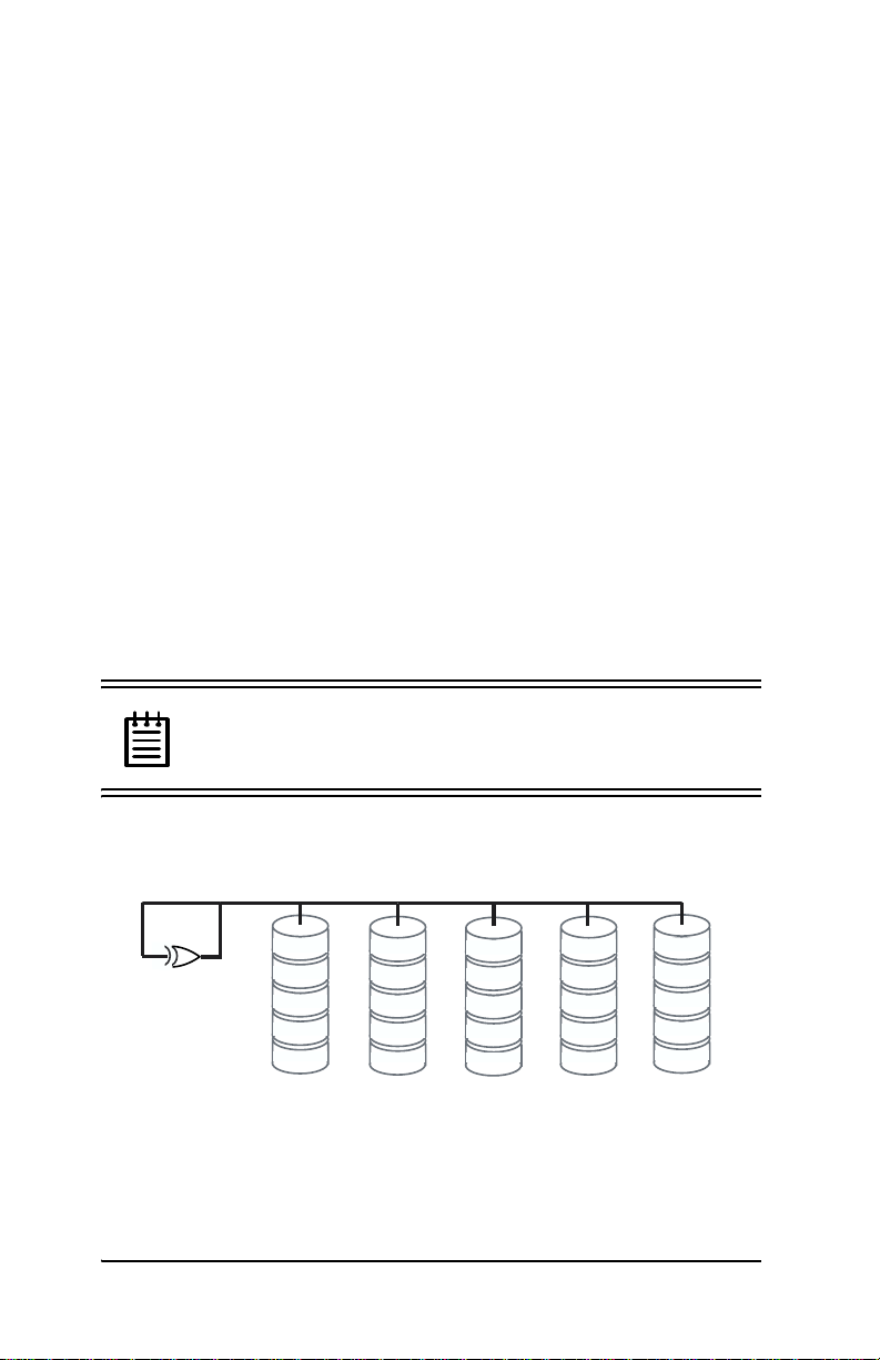
RAID 0 arrays maximize performance and capacity
When drives are configured in a striped disk array (see Figure 1),
the Escala de Storage Switch distribu tes large files across the multiple disks using RAID 0 techniq ues. St riped disk array s achieve high
transfer rates because they can read or write data on more than one
drive simultaneously. Striped disk arrays give exceptional performance, particularly for data intensive applic ations such as video
editing, computer aided design and geographical information systems. Striping your disk array concatenates each drive’s capacity
www.3ware.com 7
Page 18
3ware Esca lade Storage Switch User Guide
into one large volume. The stripe size is user configurable at 64K,
128K, 256K, 512K or 1M.
Figure 1. RAID 0 Configuration Example
RAID 1 arrays offer fault tolerance
Mirrored disk arrays write data to two drives using RAID 1 algorithms (see Figure 2). This gives your syste m faul t tole rance b y preserving the data on one drive if the other drive fails. Fault tolerance
is a basic requirement for mission critical systems like web and
database servers.
RAID -1
Figure 2. RAID 1 Configuration Example
TwinStor
disk arrays
TM
T ec hnology adds per formance t o 3wa re’s mirrored
RAID -1
Traditional mirroring techniques do little to improve performance.
The adaptive algorithms found in 3ware’s TwinStor technology
boost performance by distinguishing between random and sequen-
8 www.3ware.com
Page 19
Introduction
tial read requests. For the sequential requests generated when
accessing large files, both drives are u sed, with th e heads simu ltaneously reading alternating sections of the file. For the smaller random transactions, the data is read from a single optimal drive head.
Drives can be dynamically profiled, specifically for your brand of
drive, during installation to customize the stripe size (for R AID
configurations offering variable striping) and seek algorithms.
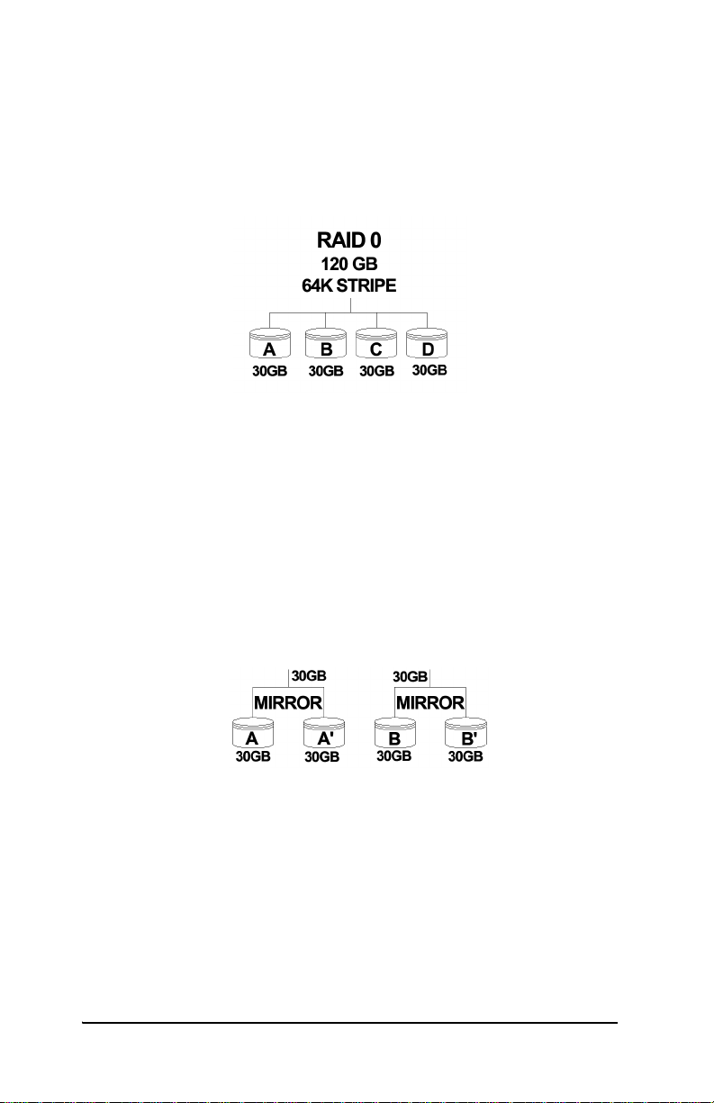
RAID 10 arrays maximize performance and fault tolerance
When drives are configured as a striped mirrored array, the disks
are configured using bot h RAID 0 and RAID 1 te chniqu es, thus the
name RAID 10 (see Figure 3). A minimum of four drives are
required to use this te chnique. The fi rst two driv es are mirror ed as a
fault tolerant array using RAID 1. The third and fourth drives are
mirrored as a second fault tolerant array using RAID 1. The two
mirrored arrays are then grouped as a striped RAID 0 array using a
two tier structure. Higher data transfer rates are achieved by leveraging TwinStor and striping (64K, 128K, 256K, 512K or 1M) the
arrays. RAID 10 is available on the four and eight port Escalade
Storage Switches.
Figure 3. RAID 10 Configuration Example
www.3ware.com 9
Page 20
3ware Esca lade Storage Switch User Guide
RAID 5 arrays optimize performance, fault tolerance, high capacity and storage efficiency
The RAID 5 configuration features the data striping of RAID 0
combined w i th the parity of RAID 4. Using a simpl e parity (exclusive OR) function, RAID 5 can tolera te the lo ss of one dri ve. Parity
information is distributed across all drives rather than being concentrated on a single disk (see Figure 4). This avoids throughput
loss due to contentio n for the pari ty drive. You can use hot spares to
rebuild a failed drive “on-the-fly”.
RAID 5 capa city = size of smallest drive × (number of drives - 1).
In addition, th e array’s storage efficien cy increa ses with the number
of disks; from 66.7 % for 3 drives to 87.5 % for 8 drives: storage
efficiency = (number of drives -1)
÷ (number of drives).
Unlike all other RAID configu rations that offer data stri ping, except
for RAID 1, RAID 5 stripe s ize is limited to 64k.
Note: BIOS will reject the creation of a RAID 5 array
having less than 3 drives.
RAID 5
0 parity
A1
A2
A3
A4
A Blocks
B0
1 parity
B2
B3
B4
B Blocks C Blocks D Blocks
C0
C1
2 parity
C3
C4
D0
D1
D2
3 parity
D4
Figure 4. RAID 5 Configuration Example
10 www.3ware.com
E0
E1
E2
E3
4 parity
E Blocks
Page 21

Introduction
R5 Fusion
performance
TM
Technology significantly improves RAID 5 write
3ware’s R5 Fusion significantly improves RAID 5 write performance for both large sequential and small random transactions.
This advanced block caching firmware technology is combined
with StorSwitch to deliv er extr emely hig h performanc e for RAID 5
write operations.
Note: R5 Fusion is available only with Escalade 7450
and 7850 storage switches.
Background Media Scan and Dynamic Sector Repair enhance data integrity
Background Media Scan is an embedded feature that performs a
read-scan of all dis ks in an array. An error notification is posted fo r
each read error detected (see “Screen Displa y Messages” on
page 145). If the array is redundant (i.e., RAID 1, 10 and 5)
Dynamic Sector Repair automatically recovers the redundant data
and rewrites it to the logical defective location. The drive reallocates the sector where the read error occurred and a notification of
repair is posted. This results in the restoration of drive and data
integrity; the primary and redundant data are again both valid.
Configure and manage your disk arrays
The 3ware Disk Arr ay Conf igur ati on Ut il it y is a BIOS level tool
for creating, deleting, maintaining disk array s and rebuilding mirrored arrays. From the 3DM Disk Array Configuration Utility,
you can also specify hot spares from available drives to be dynamically subst ituted for a failed drive in a mirrored array. Refer to the
3ware Disk Array Configuration Utility chapter.
SMART Monitoring (Self-Monitoring, Analysis and Reporting
Technology) adds monitoring and troubleshooting functionality by
www.3ware.com
Page 22

3ware Esca lade Storage Switch User Guide
automatically chec ki ng a di sk drive's health and repor ti ng pot ent ial
problems. It allows you to take proactive steps to prevent impending disk crashes.
3DM Disk Management Utility runs in the background on the
Escalade Storage Switch’s host and allows you to monitor the
switch and rebuild mirrored arrays remotely via a standard web
browser. To remotely a ccess 3DM, you are not required to insta ll
any software on your system but you must have access to the network with the Escalade Storage Switch. 3DM supports hot spare
and hot swap for mirrored arrays. Hot swap allows users to replace
a failed drive in a mirrored array whi l e the system remains up.
Refer to the 3DM Disk Management Utility chapter.
To create, delete or verify arrays, you must use the 3ware Disk
Array Conf iguration Utility. To check array configuration or status, disable write cache, select a hot spare or rebuild a mirrored
array, you can use the 3ware Disk Array Configuration Utility at
BIOS time or 3DM Disk Management Utility in real time . Hot
swap is only available through the 3DM Disk Management Util-
ity.
12 www.3ware.com
Page 23
Quick Installation Guide
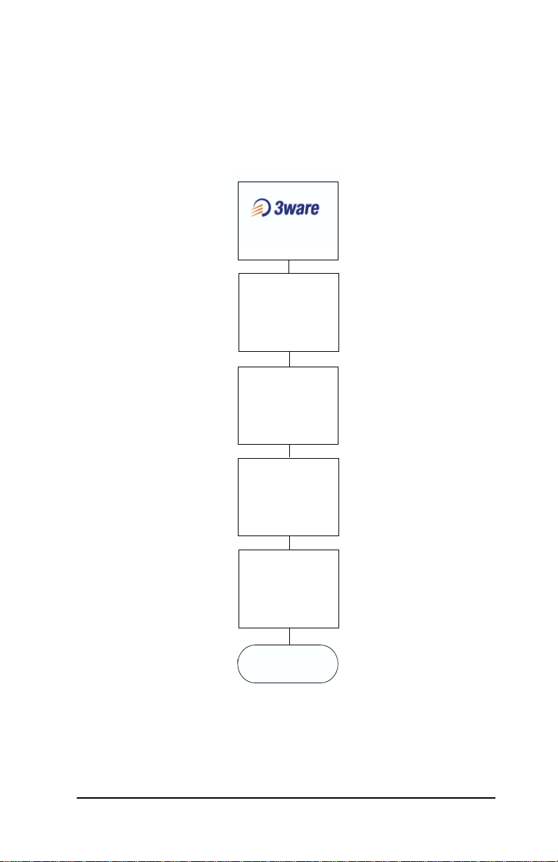
Quick Installation Guide
Install
Storage Switch
Refer to
Hardware Installation
Create Arrays
ALT-3 at Boot
Refer to
3ware Disk Array
Configuration Utility
Install System
Driver
Refer to
Windows Installation
or
Linux Installation
RAID Array
Background
Initialization Process*
Install 3DM
Refer to
3DM
Disk Management
Utility
Installation
Complete
* This process does not interfere with the installation of 3DM or the use of the array.
www.3ware.com 13
Page 24

3ware Esca lade Storage Switch User Guide
Step 1. Instal l the Escalade Storage Switch
Install the two, four or eight port Escalade Storage Switch in an
available PCI slot. Slo ts closest to the Accelerated Graphics Port
give the best performance. The blue end of the ribbon interface
cable must be connected to the storage switch and the black end
must be connected to the drive.
Step 2. Create Arrays
Verify your boot device precedes the Escalade Storage Switch in
the boot sequence, then press Alt-3 to activate the 3ware Disk
Array Conf iguration Utility at boot time. Specify RAID arrays
and hot spares.
Step 3. Install System Drivers
The Escalade Stor age Switc h driver s must be in stall ed accor ding to
the type of installation and the operating system. Installations
include:
• Installing the storage switch while installing the operating system.
• Installing the storage switch on systems that boot from a different device.
• Replacing an existing storage switch with a new version of the
switch.
Operating systems supporting the Escalade Storage Switch include:
• Windows NT 4.0
• Windows 98 SE or ME
• Windows XP
• Windows 2000
• Red Hat Linux
• SuSE Linux
14 www.3ware.com
Page 25

Quick Installation Guide
Step 4. RAID Array Background Initializatio n Process
The completion of the system driver installation will start the RAID
array initialization process. This process may take several hours,
but it does n ot interfer e with the installation of 3DM or the use of
the array.
Step 5. Install 3DM
Install 3DM for Windows or Linux from the 3DM installation CDROM.
Windows
a:\setup from Run... in the Start menu.
Linux
mount /dev/hdc /mnt
cd /mnt
./install.3dm
Answer questions concerning e-mail notification and the port number for WEB monitoring.
cd /
umount /mnt
Note: When specifying multiple e-mail addresses for
notification, separate e-mail addresses using a comma.
www.3ware.com 15
Page 26

3ware Esca lade Storage Switch User Guide
16 www.3ware.com
Page 27
Hardware Installation
Hardware Installation
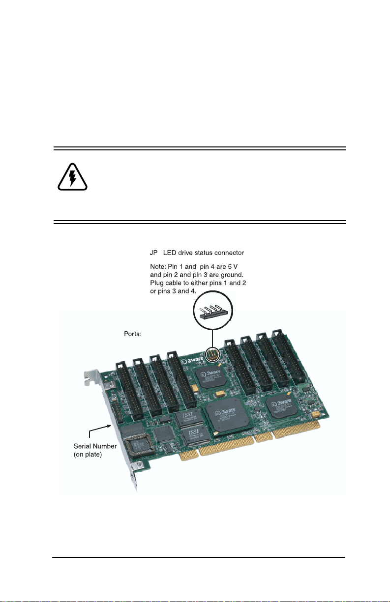
Figure 5 shows ports and connectors on the Escalade 7850 Storage
Switch.
Warning: Before proceeding with hardware installa-
tion, read the Before You Begin section completely that
describes person al and syste m precau ti ons. Fai ling to do
so may result in personal injury or damage to your computer or the Escalade Storage Switch.
2
1
0
1
2
3
4
5
6
7
Figure 5. 8-Port Escalade 7850 Storage Switch
Layout
www.3ware.com 17
Page 28

3ware Esca lade Storage Switch User Guide
To remove an existing Escalade Storage Switch
1 I f the computer is running, shut it down. Turn off power to the
computer and disconnect the power cord from the outlet.
2 Open the computer case according to the manufactur er’ s in struc -
tions.
3 Disconnect the disks from the existing Escalade Storage Switch
installed in your system. If your boot disk is connected to the
storage switch and you intend to retain it as your boot device,
note or mark which physical disk is connected to slot 0 on the
switch. This disk should be reconnected to slot 0 on the new
storage switch. Preserving the slot order of how the other drives
are connected is unimportant, even if the disks are part of a disk
array, although it is recommended that a plug-to-plug replacement is followed.
4 Remove the screw in the metal bracket at the end of the old stor-
age switch. Save the screw for installing the new switch.
5 Gently remo ve the storage switch fro m the PCI slot .
6 Remove the cables from the storage switch and discard. Reusing
interface cables is not recommended.
Connect the interface cables to the Escalade Storage Switch
1 Connect the interface cables supplied with the product to the
storage sw itch.
Note: UltraATA-66 and UltraATA-100 drives
require 40-pin, 80-conductor ribbon cables. These
cables have color coded ends. For optimum performance, the blue end must be connected to the storage
switch and the black end must be connected to the hard
drive.
2 One edge of each interface cable should have a colored (usually
red) line denoting the conductor to Pin 1. Align the storage
18 www.3ware.com
Page 29
Hardware Installation
switch so that the colored line is toward the top edge of the
switch. Mate the connectors carefully without bending any pins.
3 I nstall the other connectors in the same manner.
Install the Escalade Storage Switch in the computer
1 I f the computer is running, shut it down. Turn off power to the
computer and disconnect the power cord from the outlet.
2 Open the computer case according to the manufacturer’s instruc-
tions.
3 Find the PCI slot you want to use for the storage switch.
Hint: Cable routing may be easier if you install the
storage switch next to an open slot.
4 Remove the metal filler bracket for the slot. Save this screw; it
will be used to secure the storage switch after you have seated it
in the slot.
Hint: While the storage switch runs properly in any
PCI slot, not all slots give equal performance du e to the
architecture of the PC I bus. In our laboratories, we have
noticed that the slots closest to the Accelerated Graphics
Port (AGP) typically give the best performance.
5 Line the storage switch up so that all pins make proper contact
with the PCI slot pins when pu shed into plac e. The black end r ail
opposite the metal bracket may be removed if needed to fit the
storage switch inside the chassis. The short 4-port or 8-port
Escalade Stor age Switc h is keye d to ensu re prope r insta llation in
a full-sized PCI slot.
www.3ware.com 19
Page 30

3ware Esca lade Storage Switch User Guide
6 Ensure that the contacts will mate with both grooves in the slot.
Press down gently on the edge of the storage switch directly
above the slot until the it is fully seated.
7 Check that the storage switch’s metal bracket covers the hole in
the case and secure the bracket with the screw that was used to
secure the filler bracket in step 4.
Connect the drives to the interface cables
1 Be sure to use the supplied cables. With the higher speeds of
UltraATA-100 and UltraATA-66, using quality cables is important.
2 Before connecting your drives, check your drives’ jumper set-
ting. The range of settings provided vary by manufacturer as do
the method for adjusting them. Refer to information provided
with your drives for the me th od re qui red to set them. To operate
properly, the Escalade Storage Switch r equi res that drives be se t
as Single (if available on your drive) or Master.
3 I f your drives are not already installed in the computer chassis,
do so now. Be sure that the drives are connected to the power
supply. Y-splitter power suppl y co nnec tors are included in some
kits in case you need additional power supply connections.
4 For each drive, select the black en d of a n int erfac e cabl e n ot con -
nected to the storage switch and plug it into the drive or drive
carrier. The cable’s colored edge denotes Pin 1 and should be
adjacent to the 4-pin power plug.
Check your installation and close the case
1 After all of the drives are connected to the storage switch and it
is installed in its slot, verify that th e cables do no t interfere w i th
the operation of any other components in the case or block the
flow of cooling air.
2 Close the case and reconnect the power cables.
20 www.3ware.com
Page 31

Hardware Installation
Check motherboard boot sequence
Using your computer’s Setup utility, ensure that your boot device
precedes the Escalade Storage Switch in the boot sequence. If you
have other disks installed on the motherboard, the storage switch
precedes them in boot order.
www.3ware.com 21
Page 32

3ware Esca lade Storage Switch User Guide
22 www.3ware.com
Page 33

3ware Disk Array Configuration Utility
3ware Disk Array
Configuration Utility
The 3ware Disk Array Configuration Utility all ows you to crea te
disk arrays by combining disks, deleting disks or breaking disk
arrays back into their member disks. You can also specify an available drive as a hot spare. If an array becomes degraded, the hot
spare will automaticall y be substitu ted for the fau lted drive.
Note: The BIOS will not be in stalled if no drives are
attached to the Escalade Storage Switch. The storage
switch shares one IRQ on the PCI bus.
Hot Spare and Hot Swap
Hot Spare is the label given to a drive that is available, active and
designated as a spare. This designated drive is applied automatically when a drive deg rades and the a rray is r ebuilt. Hot Swap is the
term applied to the process of swapping out a degraded drive, programmatically and using 3DM, with a pre-assigned spare.
There are two methods for adding a drive as a spare. You may designate a drive as a Hot Spare during the BIOS page display, or you
may designate a drive as a Hot Spare through the 3DM configure
page. These two methods are discussed below.
BIOS Screen
When designating spare in the BIOS screen, it is assumed that as
you are creating your array, you are “setting aside” drive(s) as Hot
Spares. This is done by using the S key on the selected drive. Leaving a drive undesignated results in it becoming a JBOD drive.
JBOD drives become available to the operating system as d i stinct
volumes, and, consequently, they cannot be designated as spares at
www.3ware.com 23
Page 34

3ware Esca lade Storage Switch User Guide
a later time. I f a s pare is de sig nated in th e BIOS s creen, th e desi gnation and configuration is in effect from this point on. The spare
drive will be displayed as a Hot Spare in the 3DM configuration
page.
3DM Configure Page
In order to designate an available drive as a spare from the 3 DM
configure page, you must ensure that the drive is not a JBOD drive.
To designate a drive as a Hot Spare from this page, you must use
one of the two following methods:
1 Install the drive at the operating system level while the syst em is
powered. This should only be done with an approved and recognized drive-carrier swap. If you do not use an approved and recognized drive-carrier swap, connecting interface cables and
power cables can/will crash the system from bus or power supply issues.
2 Shut down the system (Windows/Linux system shutdown);
install the drive and do no t go int o the BI OS scree n. When 3 DM
is invoked, the configuration page may show this drive as dead.
Select Issue a Removed Drive and then select Add Spare. The
drive should appear as a Hot Spare.
Invoking the 3ware BIOS tool
Reboot your system. During the boot phase, wait until you see a
screen similar to Figure 6.
24 www.3ware.com
Page 35

3ware Disk Array Configuration Utility
Figure 6. 3ware BIOS Tool
Press Alt-3 immediately to bring up the 3war e Disk Arr ay Config -
uration display.
Note: If drives are attached and you do not want to
install the 3ware BIOS, press Alt-b to bypass the BIOS
installation.
Exiting the 3ware BIOS tool
To save your configuration modifications hit the F8 key. After you
have hit the F8 key to commit yo ur changes , a li st of af fect ed drive s
will be displayed and you will be asked to confirm your configuration. The booting process will resume. If you have selected mirrored arrays after the operating system is running, the Escalade
Storage Switch will automatical ly run a backgroun d initializat ion to
verify that both disks in the arrays are identical.
www.3ware.com 25
Page 36

3ware Esca lade Storage Switch User Guide
To exit the 3ware Disk Array Configuration Utility without saving
your changes hit Esc.
Determining your configuration
Caution: Configuring a disk array writ es for mat-t ype
data onto it s member disks and overwrites all the files
on those disks. Be sure to back up data that requires
retention.
With a 2-port Escalade Storage Switch you are limited to a twodrive JBOD (Just a Bunch of Disks), or a two-drive RAID 0 or
RAID 1 array. With a 4-port Escalade Storage Switch, you can
combine two to four disks into a single array. With four disks you
can create a four-drive RAID 0 array, two RAID 1 arrays, one
RAID 5 array or one RAID 10 array.
The 4-port configuration can be duplicated using the 8-port
Escalade Storage Switch. In addition, you may also create a five,
six, seven or eight-dr ive RAID 0 or RAID 5 arra y, or an eight-drive
RAID 10 array .
The 3ware Disk Arra y Configur ation main displa y shows the current disk drive configuration.
• Av ailable Drives reports independent drives (JBOD) not ass oci ated with an array.
• Disk Arrays lists any existing arrays along with their member
disks and hot spares.
26 www.3ware.com
Page 37

3ware Disk Array Configuration Utility
Figure 7. Disk Array Configuration Main Display, RAID 1
Example
Throughout the utility (see Figure 7) use the Up and Down arrow
keys to navigate, Enter to select the disks or buttons and F1 for
context sensitive help. Toggle Hot Spare verbiage is black when
the cursor is over a drive that can be specified as a hot spare and
gray when hot spare cannot be specified. If you’ve made mistakes
and want to start over, pressing F6 will return your starting values.
Pressing Escape will exit the configuration utility as well as abandon your changes. Pressing F8 will save your changes and exit the
utility.
Displaying advance details
Selecting Shift-F5 will show the software versions (BIOS, Firmware, monitor) and slot # of the 3ware card (see Figure 8). Press
Escape to return to the main 3ware Disk Arra y Configura t ion
screen.
www.3ware.com 27
Page 38

3ware Esca lade Storage Switch User Guide
Figure 8. Disk Array Advance Details Screen
Creating a disk array
To create an array, first select the drives to be included by navigating the cursor over each drive and pressing Enter (see Figure 9).
An asterisk in the left most column indicates the drive is selected.
You may include from two to eight drives in the array by selecting
drives from the A vailable Drives section. To include drives that are
part of an existing disk a rray you must first delete the array.
28 www.3ware.com
Page 39

3ware Disk Array Configuration Utility
3ware Disk Array Configuration
Available Drives:
*Port 0 - QUANTUM FIREBALLP LM30 30.0GB
*Port 1 - QUANTUM FIREBALLP LM30 30.0GB
Port 2 - QUANTUM FIREBALLP LM30 30.0GB
Port 3 - QUANTUM FIREBALLP LM30 30.0GB
Disk Arrays:
Create Array
Alt-F1
Help
Restore Initial Values
F6
Delete Array
Previous/Next
Maintain Array
Toggle Hot Spare
$
Cancel
Esc
Rebuild Array
Enter
Select/Deselect
F8
Done
Figure 9. Selecting Drives for a Mirrored Array
Determining your configuration
Hint: The capacity of each drive is limited to the
capacity of the smallest drive in the array. The total
array capacity is defined as follows:
RAID 0: (the number of drives) X (the capacity of the smallest drive)
RAID 1: the capacity of the smallest drive
RAID 5: (the number of drives - 1) X (capacity of the smallest drive)
RAID10: (the number of drives / 2) X (capacity of smallest drive)
.
Navigate to the Create Array button after selecting all the drives
for the array. Hit Enter to bring up the Create Disk Array display
(see Figure 10 and Figure 11 for examples). Check that the proper
drives are listed.
www.3ware.com 29
Page 40

3ware Esca lade Storage Switch User Guide
Create Disk Array
Note: Creating an array will overwrite existing data on its drives.
Create a disk array from these drives:
Port 0 - QUANTUM FIREBALLP LM30 30.0GB
Port 1 - QUANTUM FIREBALLP LM30 30.0GB
Select RAID Configuration:
Array's Write Cache State:
Stripe (RAID 0)
enable
OK
Stripe Size:
Cancel
64 KB
128KB
256KB
512KB
1mb
HelpAlt-F1
Previous/Next
Change ValueEnter
CancelEsc
Figure 10. Create Disk Array Display, RAID 0 Example
30 www.3ware.com
Page 41

3ware Disk Array Configuration Utility
Create Disk Array
Note: Creating an array will overwrite existing data on its drives.
Create a disk array from these drives:
Port 1 - IBM-DTLA-387815 512 M
Port 2 - IBM-DTLA-387815 512 M
Port 3 - IBM-DTLA-387815 512 M
Select RAID Configuration:
Array's Write Cache State:
RAID 5
enable
Stripe Size:
64 KB
OK
HelpAlt-F1
Previous/Next
Cancel
Change ValueEnter
CancelEsc
Figure 11. Create Disk Array Display, RAID 5 Example
Select RAID configuration
The Escalade Storage Switch gives you a choice of four RAID configurations. Select one.
• Stripe (RAID 0): maximizes performance a nd capacit y through a
process called striping. High performance arrays write portions
of a single file across multiple drives. There is no fault tolerance.
• Mirror (RAID 1): duplicates or “mirrors” the data on both
drives. No data will be lost if one of the drives fa ils.
• RAID 10: combines mirr or ing and striping, providing both fault
tolerance and high performance. RAID 10 arrays require a
minimum of four drives. Configurations consist of 4, 6 or 8
drives.
• RAID 5: combines parity da ta and stri ping, pr ovidin g fau lt toler ance, high capacity and high storage efficiency. The parity data
is distributed acr oss all drive s, rat her t han be ing con cen trate d on
www.3ware.com 31
Page 42

3ware Esca lade Storage Switch User Guide
a single disk, to avoid throughput loss due to corrections for the
parity drive. RAID 5 arrays requires a minimum of three
drives. Configurations consist of 3, 4, 5, 6, 7 or 8 drives.
3ware Disk Array Configuration
Available Drives:
Port 0 - QUANTUM FIREBALLP KX27.3 512 M
Disk Arrays:
Array Unit 1 - 3 drive 64K RAID 5 1.0GB
Port 1 - IBM-DTLA-387815 512 M
Port 2 - IBM-DTLA-387815 512 M
Port 3 - IBM-DTLA-387815 512 M
Init RAID5 Array Unit 1
Percentage done : 25%
Create Array
Alt-F1
Help
Restore Initial Values
F6
Delete Array
Previous/Next
Maintain Array
Toggle Hot Spare
$
Cancel
Esc
Rebuild Array
Enter
Select/Deselect
F8
Done
Figure 12. BIOS Initialization Screen for RAID 5
Select striping size
For a RAID 1 or RAID 10 configuration select the striping size.
Sizes of 64K, 128K, 256K, 512K or 1M are selected using the
Stripe Size box shown in Figure 10. RAID 5 only allows a 64K
stripe size.
Select write cache properties
The Escalade Storage Switch gives you a choice of disabling the
write cache for your disk arrays. Wr ite cache is used to store data
locally on the drive before it is written to the disk, allowing the
computer to continue with its next task. Enabling the write cache
results in the most efficient access times for your computer system.
32 www.3ware.com
Page 43

3ware Disk Array Configuration Utility
There may be instance s when you always wa nt the computer to wait
for the drive to write all the data to disk before going on to its next
task. For this case, you must disable the write cache. To disable the
write cache, select disable from the array’s Write Cache State
selection. The default for Write Cache State is enable.
Confirm array configuration
Select the OK button to confirm creating the array or Cancel to
reject it. The array is not actually created and no data will be overwritten until you have finished making all your changes and select
the F8 key.
For RAID 5 Arrays
Because of the Read-Modify-Write operations, zeros are first written to all dri ves in the array before th e array is functional. The
screen shown in Figure 12 appears after selecting OK to confirm
array creation.
If the write-zeros ope ration is aborted by th e user fo r any reason the
unit will go into initializing mode when restarted. This mode scans
the entire array to verify parity. If coherency problems appear the
parity will be corrected to match the data found on that stripe.
Caution: When running in initiali zing mode th e arra y
is not redundant. You cannot remove any drive.
For RAID 1 or 10 Arrays
Drives are dynamically profiled, specifically for your brand of
drive, after selecting OK to confirm array creation. This is done to
customize the stripe size (f or RAID configuratio ns offering var iable
striping) and seek algorithms.
www.3ware.com 33
Page 44

3ware Esca lade Storage Switch User Guide
Specifying a hot spare
The Escalade Storage Switch gives you the option to specify a hot
spare from one of your Available Drives. If a hot spare i s s p ec if ie d
and the mirror degrades, an event notification will be generated.
The hot spare will dynamically replace the failed drive in a mirrored array without user intervention. Select a hot spare by navigating to an Available Drive. The Toggle Hot Spare verbiage at the
bottom of the screen will be black if the drive can be used as a hot
spare. Enter s to select the hot spare or to disable the hot spare if it
is already enabled.
Note: Hot spare drives need to have the same or larger
storage capacity than the RAID 1, RAID 5 or RAID 10
drives.
Changing an existing configuration
1 Back up any disk arrays that contain data that you want to retain
before the configuration change.
2 Create new disk arrays fo llowing the instructions in the Deter-
mining your configuration, Creating a disk array and Deleting a disk array sections. You may need to delete existing
arrays to free up disks first.
3 Boot, partition and format any new disk arrays or free disks.
4 When you are finished configuring, restore from backup any
data saved from previous disk arrays
Modifying a disk array
To modify an existing array you must first delete it then recreate it
with the new drives. As with all disk array operations, there is no
way to modify an existing array without overwriting data on the
drives involved.
34 www.3ware.com
Page 45

3ware Disk Array Configuration Utility
Deleting a disk array
To delete an array (see Fig ure 13) first sele ct the array by navigating to it and hitting Enter. An asterisk in the left most column indi-
cates the array is selecte d.
3ware Disk Array Configuration
Available Drives:
Disk Arrays:
*Array Unit 0 - 4 drive 64K RAID 0 120.0GB
Port 0 - QUANTUM FIREBALLP LM30 30.0GB
Port 1 - QUANTUM FIREBALLP LM30 30.0GB
Port 2 - QUANTUM FIREBALLP LM30 30.0GB
Port 3 - QUANTUM FIREBALLP LM30 30.0GB
Create Array
Alt-F1
Help
Restore Initial Values
F6
Delete Array
Previous/Next
Maintain Array
Toggle Hot Spare
$
Cancel
Esc
Rebuild Array
Enter
Select/Deselect
F8
Done
Figure 13. Delete Disk Array Display
Navigate to the Delete Array button and hit Enter to bring up the
Delete Disk Array display. Check that the correct drives are listed.
Select the OK key to confirm deleting the array or Cancel to reject
it. Recall that the array is not actually deleted and no data will be
overwritten until you have finished making all your changes and
selected th e F8 key.
www.3ware.com 35
Page 46

3ware Esca lade Storage Switch User Guide
How to maintain or verify a disk array
The Maintain Disk Array (see Figure 14) shows the current disk
array configuration that you have selected. The array’s Write
Cache State can be changed. Refer to Select write cache properties paragraph in the Creating a disk array section. Verify Array
can be specified as no or yes. The default is no. Yes launches a fore-
ground process that checks the data integrity of a fault tolerant
array. If the verify array process determines that the mirrored drives
are not identical or the parity is not correct, the mirror is degraded
and the rebuild process is launched.
Maintain Disk Array
The array listed below can have its write cache state changed.
Verify checks the data integrity of a fault tolerant array.
Array Unit 2 - 2 drive Mirror 30.0GB
Port 2 - QUANTUM FIREBALLP LM30 30.0GB
Port 3 - QUANTUM FIREBALLP LM30 30.0GB
Array's Write Cache State:
Verify Array:
HelpAlt-F1
Previous/Next
enabled
no
OK
Cancel
Change ValueEnter
CancelEsc
Figure 14. Maintain Disk Array Display
36 www.3ware.com
Page 47

3ware Disk Array Configuration Utility
Rebuilding a mirrored disk array
Escalade Storage Switches allow you to create fault tolerant disk
arrays by selecting a mirrored RAID 1 or RAID 10 array. These
disk arrays store identical data on two or more drives to protect
against drive failur e. If one or more of the drive s of a mirrored arr ay
is removed, unplug ged or f ails on read or write requests , the array is
marked as DEGRADED and the drive is marked as Not In Use
(see Figure 15 and Figure 16).
You can still read and write data f rom a de graded di sk arr ay, but the
array will not be fault tolerant until it is rebuilt using the Rebuild
feature, described in the 3ware Disk Array Configuration Utility or
3DM Disk Management Utility chapters.
3ware Disk Array Configuration
Available Drives:
Port 2 - QUANTUM FIREBALLP LM30 30.0GB
Port 3 - QUANTUM FIREBALLP LM30 30.0GB
Disk Arrays:
Array Unit 0 - 2 drive Mirror 30.0GB DEGRADED
Port 0 - QUANTUM FIREBALLP LM30 30.0GB Not in Use
Port 1 - QUANTUM FIREBALLP LM30 30.0GB
Create Array
Alt-F1
Help
Restore Initial Values
F6
Delete Array
Previous/Next
Maintain Array
Toggle Hot Spare
$
Cancel
Esc
Rebuild Array
Enter
Select/Deselect
F8
Done
Figure 15. Degraded RAID 1 Array Drive When Not in Use
www.3ware.com 37
Page 48

3ware Esca lade Storage Switch User Guide
3ware Disk Array Configuration
Available Drives:
Disk Arrays:
Array Unit 0 - 4 drive 64K RAID 10 60.0GB DEGRADED
Port 0 - QUANTUM FIREBALLP LM30 30.0GB Not in Use
Port 1 - QUANTUM FIREBALLP LM30 30.0GB
Port 2 - QUANTUM FIREBALLP LM30 30.0GB
Port 3 - QUANTUM FIREBALLP LM30 30.0GB
Create Array
Alt-F1
Help
Restore Initial Values
F6
Delete Array
Previous/Next
Maintain Array
Toggle Hot Spare
$
Cancel
Esc
Rebuild Array
Enter
Select/Deselect
F8
Done
Figure 16. Degraded RAID 10 Array Drive When Not in Use
Note: A RAID 10 array can be configured with either
four, six or eight disks. In a 4-drive configuration, up to
two drives can be rebuilt. In a 6-drive configuration, up
to three drives can be rebuilt. In an 8-drive configuration, up to four drives can be rebuilt.
38 www.3ware.com
Page 49

3ware Disk Array Configuration Utility
Rebuilding a RAID 5 disk array
Escalade Storage Switches allow you to create fault tolerant RAID
5 disk arrays. These disk arrays achieve fault tolerance by using a
simple (exclusive OR) function to g enerate the parity data th at is
distributed on all driv es. If one of the dri ves is re moved, un plugged
or fails on read or write requests, the array is marked as
DEGRADED and the drive is marked as Not In Use (see
Figure 17). When running in Degraded mode, the missing data is
reconstructed from all non-degraded drives.
3ware Disk Array Configuration
Available Drives:
Port 0 - QUANTUM FIREBALLP KX27.3 512 M
Disk Arrays:
Array Unit 1 - 3 drive 64K RAID 5 1.0GB DEGRADED
Port 1 - IBM-DTLA-387815 512 M
Port 2 - IBM-DTLA-387815 512 M Not in Use
Port 3 - IBM-DTLA-387815 512 M
Create Array
Alt-F1
Help
Restore Initial Values
F6
Delete Array
Previous/Next
Maintain Array
Toggle Hot Spare
$
Cancel
Esc
Rebuild Array
Enter
Select/Deselect
F8
Done
Figure 17. Degraded RAID 5 Array Drive When Not in Use
As in the case of RAID 1 and 10 arr ays RAID 5 a rrays allow y ou to
read and write data from a degraded disk array, but the array will
not be fault tolerant until it is rebuilt using the Rebuild feature.
(Refer to the 3ware Disk Array Configuration Utility or 3DM Disk
Management Utility chapters for more information.)
www.3ware.com 39
Page 50

3ware Esca lade Storage Switch User Guide
Rebuilding a mirrored or RAID 5 array with no hot spare
1 Reboot the system and enter the Disk Array Configuration
Utility.
2 If your mirrored or RAID 5 array has a Not in Use member
drive, the drive may still be usable. Try rebuilding with the Not
in Use drive intact. Simply select the array and then the Rebuild
button.
3 Confirm that you selected the correct array by hitting OK in the
Rebuild confirmation display.
4 Select F8 to exit the Disk Array Configuration Utility. The
array will begin rebui lding a fter complet ion of t he oper ating sys-
tem load.
5 I f the rebuild fails and you have no Available Drives, you must
replace the drive and restart the rebuild process with the new
drive. If the rebuild process fails and you have Available
Drives, reboot the system and enter the Disk Array Configura-
tion Utility.
6 Select an available drive to replace the faulted drive in the array
by navigating the cursor over the available drive and hitting
Enter (see Figure 18). An asterisk in the left most column indi-
cates the drive is selected.
40 www.3ware.com
Page 51

3ware Disk Array Configuration Utility
3ware Disk Array Configuration
Available Drives:
Port 2 - QUANTUM FIREBALLP LM30 30.0GB
*Port 3 - QUANTUM FIREBALLP LM30 30.0GB
Disk Arrays:
*Array Unit 1 - 2 drive Mirror 30.0GB DEGRADED
Port 1 - QUANTUM FIREBALLP LM30 30.0GB
Create Array
Alt-F1
Help
Restore Initial Values
F6
Delete Array
Previous/Next
Maintain Array
Toggle Hot Spare
$
Cancel
Esc
Rebuild Array
Enter
Select/Deselect
F8
Done
Figure 18. Select Available Drive to Replace Faulted Drive,
RAID 1 Example
www.3ware.com 41
Page 52

3ware Esca lade Storage Switch User Guide
7 Navigate to the Rebuild Array button and press Enter (se e
Figure 19). A status screen will be displayed with your
requested array and member drives.
3ware Disk Array Configuration
Available Drives:
Port 2 - QUANTUM FIREBALLP LM30 30.0GB
Disk Arrays:
Array Unit 1 - 2 drive Mirror 30.0GB REBUILDING (after F8)
Port 1 - QUANTUM FIREBALLP LM30 30.0GB
Port 3 - QUANTUM FIREBALLP LM30 30.0GB
Create Array
Alt-F1
Help
Restore Initial Values
F6
Delete Array
Previous/Next
Maintain Array
Toggle Hot Spare
$
Cancel
Esc
Rebuild Array
Enter
Select/Deselect
F8
Done
Figure 19. Rebuild Array Status Display, RAID 1 Example
42 www.3ware.com
Page 53

3ware Disk Array Configuration Utility
8 Press F8 to rebuild. The rebuild confirmation screen will be dis-
played (see Figure 20).
3ware Disk Array Configuration
Creating or destroying arrays will destroy all existing data on their
member disk drives. Using a drive for a rebuild will overwrite data on
that drive.
Data on the following drives will be destroyed.
Port 3 QUANTUM FIREBALL LM30
Update configuration and exit? [Y/N]
Restore Initial ValuesF6
CancelEsc
DoneF8
Figure 20. Rebuild Confirmation Display
9Enter Y to update configurations and exit.
Auto rebuild of a mirrored or RAID 5 array
If a hot spare is specified and the mirrored or RAID 5 array
degrades, an event notification is generated and the hot spare
dynamically replaces the failed drive in the array without user intervention. Rebuild will automatically be launched as a background
process and an event notification will notify the user when the
rebuild process is complete.
www.3ware.com 43
Page 54

3ware Esca lade Storage Switch User Guide
Auto rebuild on power failure
During driver startup 3ware’s auto rebuild f eature sets a flag indicating that the driver loaded. Upon an orderly shutdown the flag is
rewritten, indicating a clean shutdown. During the next system
power cycle the firmware queries the flag. For a RAID 1 configuration, if there was a problem, the firmware degrades the secondary
drive in the array and starts the background rebuild of the mirrored
drive. When the rebuild is co mplete the two halves of the m irror
will be resynchronized. For a RAID 5 configuration, if there is a
problem, the firmware starts the background verification that
checks that the parity matches the data.
44 www.3ware.com
Page 55

Windows Installation
Windows Installation
Note: If you haven ’t yet installed th e hardware, return
to the Hardware Installation section. The hardware
must be installed before you can configure the Escalade
Storage Switch.
Windows NT 4.0 Installation . . . . . . . . . . . . . . . . . page 46
Windows 98/ME Installation . . . . . . . . . . . . . . . . . page 60
Windows 2000 or XP Installation . . . . . . . . . . . . . page 76
www.3ware.com 45
Page 56

3ware Esca lade Storage Switch User Guide
Windows NT®4.0 Installation
The Escalade Storage Switch may be configured to be your system’s boot device. Or, you can use another device such as a disk
attached to the motherb oard as your boot devi ce. Use your syst em’s
Setup utility to set t h e bo ot o rde r according to how you instal l yo ur
operating system.
If you are installing addit ional drives to a W indows NT system with
an existing Escalade Storage Switch, follow the instructions in:
Adding drives to an existing storage switch (page 47).
If Windows NT has not been installed on the system, follow the
instructions in either of the following sections (note: use of a boot
floppy diskette may be required by some systems):
Installing the storage switch and Windows NT 4.0 (page 48).
If you are installing the Escalade Storage Switch on a system that
already has Windows NT installed on a drive connected to another
switch, follow the instructions in:
Installing the storage switch on systems that boot from a different device (page 52).
If you are replacing an installed Escalade Storage Switch with a
new one, follow the instructions in:
Replacing an existing storage switch with a new version of the
switch (page 54).
Note: Windo ws NT 4.0 driver requires Se rvice Pack 4 or
later. Also, you cannot install the driver or the operating
system without having system administrator privileges.
46 www.3ware.com
Page 57

Windows NT®4.0 Installation
Adding drives to an existing storage switch
To add new drives to an existing disk array, refer to the 3ware
Hardware Installation and 3ware Disk Array Configuration Utility
chapters.
Boot the machine
1 Log in as syste m administrator.
2 Partition and format any new disk array or independent disk
using Disk Administrator in the remaining steps:
a Choose Programs from the Start menu.
b Choose Administrative Tools from the Programs menu.
c Choose Disk Administrator from the Administrative Tools
menu.
www.3ware.com 47
Page 58

3ware Esca lade Storage Switch User Guide
Installing the storage switch and Windows NT 4.0
Materials required:
• Windows NT 4.0 installation CD-ROM and diskettes
• 3ware CD-ROM
• 3ware Windows driver installation diskette
Create disk arrays
Refer to the 3ware Hardware Installation and 3ware Disk Array
Configuration Utility chapters.
Has your boot drive been partitioned?
Microsoft Windows NT 4.0 Setup occasionally has problems
installing on drive s that hav e not bee n partit ioned. If y ou are havi ng
trouble you may need to create a partition on the drive where you
plan to install Windows NT 4.0.
1Use the FDISK DOS utility to get your disk partitioned and
ready for installation quickly:
2 Boot MS-DOS and use FDISK to create a partition on the boot
drive. The partition does not need to be formatted or made
active. Wit h FDISK you are limited to 4 GB for your boot parti-
tion. If you need a larger boot space create a single small (e.g.,
100 MB) partition, then adjust the size during Windows NT 4.0
Setup.
Boot the system
Insert the Windows NT 4.0 CD-ROM into the CD-ROM drive, or
the Windows NT 4.0 diskettes into the floppy diskette drive.
48 www.3ware.com
Page 59

Windows NT®4.0 Installation
Continue with Windows NT 4.0 installation
1 When Setup is Inspecting Your Computer Hardware Config-
uration is displayed, press F6 immediately.
2 You will see a Windows NT 4.0 Setup display.
3 Press S to specify that you will be installing an additional mass
storage device. On the display that follows, select Other and
press Enter.
Install the driver using the 3ware diskette
1 You will be asked to insert a manufacturer-supplied hardware
support disk. Insert the 3ware Windows driver installation diskette into the fl oppy dr ive and pr ess Enter. DO NOT use t he dis-
kette labeled specifically for Windows NT driver installation.
2 Select the 3ware Storage Switch from the display that appears
and press Enter again. Ensur e the path t o this driv er is corr ect in
Copy manufacturer’s files from: at the bottom of the box. To
do this, type A:\winnt
3 After the dri ver is loaded from the dis kette, you will receive the
message “Setup has recognized the following mass storage
devices in your computer:” The list will contain the 3ware Stor-
age Switch. If not, check the hardware and restart this softwar e
installation. Otherwise, press Enter.
Partition device 0 to create a boot area
1 Follow the displayed instructions for Windows NT 4.0 installa-
tion as directed until the following message appears “The list
below shows existing partitions and spaces available for creating
partitions.”
2 The partitions list should contain an entry for your Escalade
Storage Switch that resembles the following: 4111 MB Disk 0 at
Id 0 on bus 0 on 3waregs m. If it does n ot includ e a 3ware en try,
check your hardware a nd restart the software installation process.
www.3ware.com 49
Page 60

3ware Esca lade Storage Switch User Guide
3 Create a partition in the unpartitioned space of device 0 for
installing Windows NT 4.0. Keep in mind that the space avail-
able in a disk array is often larger than is allowed in a single par-
tition. Format the partition as desired with FAT or NTFS.
Follow display instructions to complete W indows NT 4.0 installation
1 Continue with the normal Windows NT 4.0 installation.
2 Log in as administrator. You should see a brief splash screen
(see Figure 21) followed immediately by an “Installation Com-
plete” notification (see Figure 22).
3 Partition and format any new disk arrays or independent disks
using Disk Administrator in the remaining steps:
a Choose Programs from the Start menu.
b Choose Administrative Tools from the Programs menu.
c Choose Disk Administrator from the Administrative Tools
menu.
Figure 21. Storage Switch Quick-Splash Screen
Figure 22. Installation Complete Notification
50 www.3ware.com
Page 61

Windows NT®4.0 Installation
RAID array initialization
The completion of the system driver installation will start the RAID
array initialization process. This process may take several hours,
but it does n ot interfer e with the installation of 3DM or the use of
the array.
Install the 3DM disk management utility
Refer to the 3DM Disk Management Utility chapter.
www.3ware.com 51
Page 62

3ware Esca lade Storage Switch User Guide
Installing the storage switch on systems that boot from a different device
Materials required:
• 3ware Windows driver installation diskette
• 3ware CD-ROM
Create disk arrays
Refer to the 3ware Hardware Installation and 3ware Disk Array
Configuration Utility chapters.
Install the 3ware driver
1 Log in as system administrator when the system finishes boot-
ing.
2 Go to the Start menu, click on Settings and open the Control
Panel window.
3 Open SCSI Adapters from the Control Panel window.
4 Click on the Drivers tab in SCSI Adapters.
5 Follow the instructions in the Install/Update 3ware driver sec-
tion (page 55) to continue.
Reboot the machine
1 Remove the driver diskette, then select Yes to restart the system.
If you don’t remove the diskette, the system may not boot.
2 Log in as system administrator. You should see a brief splash
screen (see Figure 21) followed immediately by an “Installation
Complete” notification (see Figure 22).
3 Partition and format any new disk arrays or independent disks
using Disk Administrator in the remaining steps:
a Choose Programs from the Start menu.
b Choose Administrative Tools from the Programs menu.
52 www.3ware.com
Page 63

Windows NT®4.0 Installation
c Choose Disk Administrator from the Administrative Tools
menu.
RAID array initialization
The completion of the system driver installation will start the RAID
array initialization process. This process may take several hours,
but it does n ot interfer e with the installation of 3DM or the use of
the array.
Install the 3DM disk management utility
Refer to the 3DM Disk Management Utility chapter.
www.3ware.com 53
Page 64

3ware Esca lade Storage Switch User Guide
Replacing an existing storage switch with a new version of the switch
Caution: Install the correct driver (Escalade 7000 Stor-
age Switch) for the new version storage switch before
installing the switch. Your computer system will not
boot with the new version of the storage switch unless
the new version of the dr iver has been installed fi rst.
Note: Upgrading to a new version of the Escalade Stor-
age Switch does not requ ire reconfiguring the drives
connected to your switch and will not affect data stored
in your disk arrays for this and previous versions.
Update the 3ware driver
1 Backup any critical data prior to upgrading the 3ware driver.
2 Backup the appropriate 3DM alarm log:
Windows: 3waenlog.dat
Linux: /var/log/3w-aenlog.txt
See “Update the 3ware driver” on page 69 if you are using Win-
dows 98/ME and “Updating the 3war e driv er” on page 85 if you
are using Windows 2000/XP.
3 Log in to your system as system administrator.
4 Go to the Start menu, click on Settings and open the Control
Panel window.
5From the Control Panel windo w, open SCSI Adapters.
6 Click on the Drivers tab in SCSI Adapte rs.
7 Select the current driver in the SCSI Adapters window, then
click on the Remove button (see Figure 23).
8 Follow the instructions in the Install/Update 3ware driver sec-
tion (page 55) to continue.
54 www.3ware.com
Page 65

Windows NT®4.0 Installation
Figure 23. Remove Current Driver
Install/Update the 3ware driver
1 Click on the Add… button (see Figure 23). The Install Driver
dialog appears (see Figure 24).
www.3ware.com 55
Page 66

3ware Esca lade Storage Switch User Guide
Figure 24. Install Driver
2 Click on the Have Disk… button. The Install from Disk
(Figure 25) dialog appears. Insert the 3ware driver installation
diskette. DO NOT use the special diskette labeled specifically
for Windows NT driver installation.
3 Ensure that the path name is correct in Copy manufacturer’s
files from: at the bottom of the box. The correct path name will
be either the root directory or A:\winnt.
56 www.3ware.com
Page 67

Windows NT®4.0 Installation
Figure 25. Install from Disk
4The Install Driver (Figure 26) dialog box appears. Choose and
click on the appropriate dr iver name (i.e., Escala de 7000 Stor age
Switch) listed in the d ialog box t o highlig ht it, then clic k on OK.
Be sure to select the correct one, otherwise the driver update will
not be successful. A progress bar appears briefly, followed by a
System Settings Change dialog.
5 Shutdown your system.
www.3ware.com 57
Page 68

3ware Esca lade Storage Switch User Guide
Figure 26. Install Driver
Remove the existing Escalade Storage Switch and inst all the new Escalade Storage Switch
Refer to the Hardware Installati on chapter.
Reboot the machine
1 Remove the driver diskette from your PC, then restart your sys-
tem. If you don’t remove the diskette, the system may not boot.
2 I f you choose to reconfigure your disk arrays, press Alt-3 to
bring up the Disk Array Configuration Utility.
3 Log in at the ad ministrator level and wait for the sys tem to
reboot. You should see a brief splash screen (see Figure 21) fol-
lowed imm ediately by an “Install ation Complete” notification
(see Figure 22).
58 www.3ware.com
Page 69

Windows NT®4.0 Installation
4 Partition and format any new disk arrays or independent disks
using Disk Administrator in the remaining steps:
aFrom the Start menu, choose Programs.
bFrom the Programs menu, choose Administrative Tools.
cFrom the Administrative Tools menu, choose Disk Admin-
istrator.
RAID array initialization
The completion of the system driver installation will start the RAID
array initialization process. This process may take several hours,
but it does n ot interfer e with the installation of 3DM or the use of
the array.
Install the 3DM disk management utility
Refer to the 3DM Disk Management Utility chapter.
www.3ware.com 59
Page 70

3ware Esca lade Storage Switch User Guide
Windows® 98/ME Installation
Note: The procedures p rovided bel ow apply to Wi ndows
98 and Windows Millennium Edition (Windows ME)
installations.
As a Plug and Play device the Esc ala de S torag e Switch may be configured to be your system’s boot device. Or you can use another
device as the boot device, such as a disk attached to the motherboard. Use your system’s Setup utility to set the boot order according to how you install your operating system.
If you are installing an additional drive to a Windows 98/ME system with an existing Escalade Storage Switch, follow the instructions in:
Adding a drive to an existing storage switch (page 62).
If you have a new drive configuration without an operating system
and want to install Windows on a drive managed by the Escalade
Storage Switch , follow the instructions in:
Installing the storage switch w hile instal ling Windows 98/ME
(page 63).
If you are installing the sto ra ge swit ch on a system tha t al ready has
the operating system installed on a unit connected to another
switch, follow the inst ructions in:
Installing the storage swi tc h on syst ems tha t boot from another
device (page 66).
If you are replacing an installed Escalade Storage Switch with a
newer versio n, follow the instructions in:
60 www.3ware.com
Page 71

Windows® 98/ME Installation
Replacing an existing storage switch with a new version of the
switch (page 69).
Note: Windows 98 driver requires Microsoft Windows
98 Second Edition.
www.3ware.com 61
Page 72

3ware Esca lade Storage Switch User Guide
Adding a drive to an existing storage switch
To add the new drive to an existing disk array, refer to the 3ware
Hardware Installation and 3ware Disk Array Configuration Utility
chapters.
Partition and format new drive
1 Run fdisk by selecting Run... from the Start menu and typ ing
fdisk in the Run window.
2 Restart the system again and format each device: select the
device with the right mouse button in the My Computer win-
dow, then select Format... from the popup menu.
3 After formatting, reboot the system again to avoid running an
incompatible DOS mode and to avoid low performance.
62 www.3ware.com
Page 73

Windows® 98/ME Installation
Installing the storage switch while installing Windows 98/ME
Materials required:
• 3ware Windows driver installation diskette
• 3ware CD-ROM
Create disk arrays
Refer to the 3ware Hardware Installation and 3ware Disk Array
Configuration Utility chapters.
Boot the system from the Windows 98/ME diskette
1 I nsert Windows 98/ME boot disk into the floppy drive.
2 Restart your computer.
3 From the Windows 98 or ME Startup Menu, choose 1. Start
computer with CD-ROM support.
Partition the boot device using fdisk
1 I f your disks have not been partitioned you will get a message
like “Wind ows has detect ed that dri ve C does not cont ain a valid
FAT or FAT32 partition”. From the MS-DOS command prompt,
run fdisk to create a partition.
A:\> fdisk
2 When asked to enable large disk support indicate “yes” by typ-
ing Y.
3 Under FDISK Options s elect opti on 1, Create a DOS partition
or Logical DOS Drive.
4 Under Create a DOS Partition or Logical DOS Drive select
option 1, Create a Primary DOS partition.
5 When asked to use the maximum available size for a Primary
DOS Partition, indicate “yes” by typing Y. Then, press the
Escape key to return to the FDISK Options menu.
www.3ware.com 63
Page 74

3ware Esca lade Storage Switch User Guide
6 After the primary DOS partition is created for your boot device,
you may partition any other devices on your system. Select
option 5 to change the current drive and then repeat steps 3-5.
7 Press the Escape key several times as directed to exit fdisk and
return to the MS-DOS prompt.
Restart the machine and format the boot device
1 As you did before, choose 1. Start computer with CD-ROM
support.
2 I f you get the same message (e.g., “Windows has detected that
drive C does not contain a valid FAT or FAT32 partition”) your
partition was not created properly. Return to the Partition the
boot device using fdisk and try again. You may have restarted
without exiting all the way to the MS-DOS prompt.
3 At the MS-DOS prompt, format your boot device.
A:\> format C:
Continue the standard Windows 98/ME installation
1 Insert the Windows 98/ME CD-ROM into your CD-ROM drive.
2 From the MS-DOS prompt, type setup to continue with the stan-
dard Windows 98 or ME installation.
3After ScanDisk finishes, type X for exit.
4 Follow the display instruc tions. Note that the machine restarts
several times in the process.
5 Install the 3ware dr iver. Refer to the Install 3ware driver section.
64 www.3ware.com
Page 75

Windows® 98/ME Installation
Partition and format other devices
Note: If you have disks or disk arrays other than your
boot device on the st orage switch, y ou must partition a nd
format them before they can be written to or read f rom.
1 I f you have other disk units to partition, run fdisk by selecting
Run... from the Start menu and typing fdisk in the dialo g.
2 Restart the system again and format each device.
RAID array initialization
The completion of the system driver installation will start the RAID
array initialization process. This process may take several hours,
but it does n ot interfer e with the installation of 3DM or the use of
the array.
Install the 3DM Disk Management Utility.
Refer to the 3DM Disk Management Utility chapter.
www.3ware.com 65
Page 76

3ware Esca lade Storage Switch User Guide
Installing the storage switch on systems that boot from a different device
Materials required:
• 3ware Windows driver installation diskette
• 3ware CD-ROM
Create disk arrays
Refer to the 3ware Hardware Installation and 3ware Disk Array
Configuration Utility chapters.
Install the 3ware driver
As a Plug and Play device Windows 98/ME will recognize the
Escalade Storage Switch and automatically bring up the Add New
Hardware Wizard, which will guide you in installing the new
3ware driv er (see Figure 27). When the Add New Hardware Wiz-
ard screen appears con ti nue t o the Install/Update 3ware driver sec-
tion. Perform the follo wing steps on ly if this Wizard do es not
appear on your screen or was cancelled for some reason:
1 Log in after Windows installatio n is complete and insert th e
3ware Windows driver installation diskette.
2From the Start menu, select Setting, then Control Panel.
3 Double click on Add New Hardware icon. When the Add New
Hardware wizard lists devices that need to be installed, select
the SCSI Controllers.
4 Continue to the Install/Update 3ware driver section.
66 www.3ware.com
Page 77

Figure 27. Add New Hardware Wizard
Windows® 98/ME Installation
Partition and format units on storage switch
1 I f you have other disk units to partition, run fdisk by selecting
Run... from the Start menu and typing fdisk in the Run win-
dow.
2 Restart the system again and format each device: select the
device with the right mouse button in the My Computer win-
dow, then select Format... from the popup menu.
3 After formatting, reboot the system again to avoid running an
incompatible DOS mode and low performance.
www.3ware.com 67
Page 78

3ware Esca lade Storage Switch User Guide
RAID array initialization
The completion of the system driver installation will start the RAID
array initialization process. This process may take several hours,
but it does n ot interfer e with the installation of 3DM or the use of
the array.
Install the 3DM disk management utility
Refer to 3DM Disk Management Utility chapter.
68 www.3ware.com
Page 79

Windows® 98/ME Installation
Replacing an existing storage switch with a new version of the switch
Caution: Install the correct driver (Escalade 7000 Stor-
age Switch) for the new version Escalade Storage
Switch before installing the switch. Your system may
not boot with the new version of the storage switch
unless the new version of the driver has been installed
first.
Note: Upgrading to a new version of the Escalade Stor-
age Switch does not require reconfiguring the drives
connected to your switch and will not affect data stored
in your disk arrays for this and previous versions.
Materials required:
• 3ware Windows driver installation diskette
• 3ware CD-ROM
Update the 3ware driver
1 Backup any critical data prior to upgrading the 3ware driver.
See “Update the 3ware driver” on page 54.
2 Log in to your system.
3 Go to the Start menu, click on Settings and open the Control
Panel window.
4 Click on the System icon from the Control Panel window.
5 Click on the Device Manager tab.
6 Open the SCSI Adapters selection.
7 Locate and double-click on 3ware Storage Switch. The 3ware
Storage Switch Properties pop-up menu appears.
www.3ware.com 69
Page 80

3ware Esca lade Storage Switch User Guide
8 Click on the Driver tab (see Figure 28).
Figure 28. 3ware Storage Switch Properties Display
9 Click on the Update Driver… button and press Next on the
Update Device Driver Wizard.
70 www.3ware.com
Page 81

Windows® 98/ME Installation
Install/Update the 3ware driver
1 When you see the window in Figure 29 you MUST select “Dis-
play a list of all the drivers in a specific location, so that you can
select the driver you want.”
Figure 29. Install Hardware Device Drivers
2The Select a Device Driver dialog appears (see Figure 30).
Click on the Have Disk… button.
www.3ware.com 71
Page 82

3ware Esca lade Storage Switch User Guide
Figure 30. Select a Device Driver Display
3The Install from Disk (Figure 31) dialog appears. Insert the
3ware driver installation diskette and type the correct path name
in Copy manu factur er’ s file s fr om: near the botto m of the box.
The correct path name will be either the A:\win98 directory or
the root directory.
72 www.3ware.com
Page 83

Windows® 98/ME Installation
Figure 31. Install from Disk
4The Update Driver dialog box appears (see Figure 32). Click
on the corr ect storage switch listed in the dialog box to select it,
then click on Next.
Figure 32. Update driver
www.3ware.com 73
Page 84

3ware Esca lade Storage Switch User Guide
5 The final update driver screen should appear (Figure 33), fol-
lowed by a progress bar which appea rs briefl y, then by a System
Settings Change dialog.
Figure 33. Final driver installation screen
6 Shutdown your system and log back in at the administrat or level,
if your system is connected to a network. When the system has
rebooted you should see a brief splash screen (see Figure 34),
followed immediately by an “Installatio n Complete” notif ication
(see Figure 35).
Figure 34. Storage Switch Quick-Splash Screen
74 www.3ware.com
Page 85

Windows® 98/ME Installation
Figure 35. Installation Complete Notification
Remove the existing Escalade Storage Switch and inst all the new Escalade Storage Switch
Refer to the Hardware Installati on chapter.
Reboot the machine
1 I f you choose to reconfigure your disk arrays, press Alt-3 to
bring up the Disk Array Configuration Utility.
2 I f you reconfigure your disk arrays, partition and format any
new disk arrays or freed disks. To partition, run fdisk by select-
ing Run... from the Start menu and typing fdisk in the Run
window.
3 To format, restart the system again and log in. Select the device
with the ri ght mouse bu tton in the My Computer window and
select Format... from the popup menu.
4 After formatting, reboot the system again to avoid running an
incompatible DOS mode and low performance.
www.3ware.com 75
Page 86

3ware Esca lade Storage Switch User Guide
Windows
®
2000 or
Windows XP Installation
As a Plug and Play device, the Escalade Storage Switch may be
configured to be you r syst em’s boot device. Or, you ca n use anot her
device as your boot device, such as a disk attached to the motherboard. Use your system’s Setup utility to set the boot order according to how you install your operating system.
If you are installing an additional drive to a Windows 2000 XP system with an existing Escalade Storage Switch, follow the instructions in:
Adding a drive to an existing storage switch (page 78).
If you have a new drive configuration without an operating system
and want to install Windows on a drive managed by the Escalade
Storage Switch , follow the instructions in:
Installing the storage switch while installing Windows 2000 or
XP (page 79).
If you are installing the Escalade Storage Switch on a system that
already has the operating system installed on a unit connected to
another storage switch, follow the instructions in:
Installing the storage swi tc h on syst ems tha t boot from another
device (page 82).
If you are replacing an installed Escalade Storage Switch with a
newer versio n, follow the instructions in:
Replacing an existing Escalade Storage Switch with a new version of the switch (page 85).
76 www.3ware.com
Page 87

Windows® 2000 or Windows XP Installation
Note: 3ware supports released versions of Windows
2000 and Windows XP only. We recommend that the
user upgrade to the latest service packs available for
Windows 200 0 and Windows XP. The driver or t he o p er ating system cannot be installed unless you have administrator privileges for your system.
www.3ware.com 77
Page 88

3ware Esca lade Storage Switch User Guide
Installing a drive to an existing storage switch
To add the new drive to an existing disk array, refer to the 3ware
Hardware Installation and 3ware Disk Array Configuration Utility
chapters.
Boot the machine
Continue with the following steps to make the new disk array or
independent disk accessible to Windows 2000 or XP:
1 Boot the system and log in as a system administrator.
2 Partition and format the new arrays or disks using the Adminis-
trative Tools from the Start menu:
a Choose Computer Management from the Administrative
Tools menu.
b Select Storage.
c Select Disk Management.
4 Follow the steps the appear on-screen to write a signature to the
drive.
5 Right click on the drive and select Create Volume.
6 Follow the steps that appear on-scr een to create a volume and to
assign a drive letter.
78 www.3ware.com
Page 89

Windows® 2000 or Windows XP Installation
Installing the storage switch while installing Windows 2000 or Windows XP
Materials required:
• Windows 2000 or XP installat ion CD-ROM
• 3ware Windows driver installation diskette
• 3ware CD-ROM
Create disk arrays
Refer to the 3ware Hardware Installation and 3ware Disk Array
Configuration Utility chapters.
Installing with the Initial Operating System Build
1 Boot from the Windows 2000 or XP CD and press F6 when the
message: “Press F6 if you need to install a 3rd party SCSI or
RAID driver” appears at the bottom of the display.
2 When you get the mess age : “ Set up c ould not determine the typ e
of one or more mass storage devi ce s or you have chosen to manually specify and adapter…” press S to specify that you have an
additional disk storage switch.
3 I nsert the 3ware driver diskette and press Enter.
4 A box with 3war e Storage Switch is displayed. Press Enter to
select it.
5Press S if you have additional devices to add. Otherwise, press
Enter.
Continue with Windows 2000 or XP installat ion
Continue with the normal Windows 2000 or XP installation at this
point.There are no instructions af ter installing the driver that are
specific to 3ware. Ref er to th e W indo ws 2000 or XP do cumentati on
supplied by Microsoft if you need additional instructions.
www.3ware.com 79
Page 90

3ware Esca lade Storage Switch User Guide
Reboot the machine
When you reboot the system, log in as system administrator. You
should see a brief splash screen (see Figure 36), followed immediately by an “Installation Complete” notification (see Figure 37).
Figure 36. Storage Switch Quick-Splash Screen
Figure 37. Installation Complete Notification.
Continue with the following steps to make any new disk arrays or
independent disks accessible to Windows 2000 or XP.
1 Remove the driver diskette, then select Yes to restart the system.
The system may not boot if you don’t remove the diskette.
2 Partition and format the new arrays or disks using Disk Admin-
istrator:
a Choose Administrative Tools from the Start menu.
b Choose Computer Management from the Administrative
Tools menu.
c Select Storage.
d Select Disk Management.
80 www.3ware.com
Page 91

Windows® 2000 or Windows XP Installation
5 Follow the steps the appear on-screen to write a signature to the
drive.
6 Right click on the drive and select Create Volume.
7 Follow the steps the appear on-screen to create a volume and to
assign a drive letter.
RAID array initialization
The completion of the system driver installation will start the RAID
array initialization process. This process may take several hours,
but it does n ot interfer e with the installation of 3DM or the use of
the array.
Install the 3DM disk management utility
Refer to the 3DM Disk Management Utility chapter.
www.3ware.com 81
Page 92

3ware Esca lade Storage Switch User Guide
Installing the storage switch on systems that boot from a different device
Materials required:
• 3ware Windows driver installation diskette
• 3ware CD-ROM
Create disk arrays
Refer to the 3ware Hardware Installation and 3ware Disk Array
Configuration Utility chapters.
Install the 3ware driver
As a Plug and Play device, Windows 2000 or XP recognizes the
Escalade Stora ge Swit ch and brings up the Found New Hardware
Wizard which guides you in installing the 3ware driver (see
Figure 38). Continue to the Install/Update 3ware driver section.
82 www.3ware.com
Page 93

Windows® 2000 or Windows XP Installation
Figure 38. Found New Hardware Wizard.
Reboot the machine
Log in as system administrator when you reboot the system. You
should see a brief splash screen (see Figure 36), followed immediately by an “Installation Complete” notification (see Figure 37).
Continue with the following steps to make any new disk arrays or
independent disks accessible to Windows 2000 or XP.
1 Remove the driver diskette, then select Yes to restart the system.
The system may not boot if you don’t remove the diskette.
2 Partition and format the new arrays or disks using Disk Admin-
istrator:
a Choose Administrative Tools from the Start menu.
b Choose Computer Management from the Administrative
Tools menu.
www.3ware.com 83
Page 94

3ware Esca lade Storage Switch User Guide
c Select Storage.
d Select Disk Management.
5 Follow the steps the appear on-screen to write a signature to the
drive.
6 Right click on the drive and select Create Volume.
7 Follow the steps the appear on-screen to create a volume and to
assign a drive letter.
RAID array initialization
The completion of the system driver installation will start the RAID
array initialization process. This process may take several hours,
but it does n ot interfer e with the installation of 3DM or the use of
the array.
Install the 3DM disk management utility
Refer to the 3DM Disk Management Utility chapter.
84 www.3ware.com
Page 95

Windows® 2000 or Windows XP Installation
Replacing an existing storage switch with a new version of the switch
Caution: Install the correct driver (Escalade 7000 Stor-
age Switch) for the new version Escalade Storage
Switch before installing the switch. Your system may
not boot with the new version of the storage switch
unless the new version of the driver has been installed
first.
Note: Upgrading to a new version of the Escalade Stor-
age Switch does not require reconfiguring the drives
connected to your switch and will not affect data stored
in your disk arrays for this and previous versions.
Materials required:
• 3ware Windows driver installation diskette
• 3ware CD-ROM
Updating the 3ware driver
1 Backup any critical data prior to updating the 3ware driver.
See “Update the 3ware driver” on page 54.
2 Log in to your system as system administrator.
3 Go to the Start menu, click on Settings and open the Control
Panel window.
4From the Control Panel window, click on the System icon.
5 Click on the Hardware tab and then click on the Device Man-
ager tab.
6 Open the SCSI and Raid Controllers selection.
www.3ware.com 85
Page 96

3ware Esca lade Storage Switch User Guide
7 Locate and double-click on 3ware Storage Switch. The 3ware
Storage Switch Properties pop-up menu appears.
8 Click on the Driver tab (see Figure 39).
Figure 39. 3ware Storage Switch Properties Display
9 Click on the Update Driver… button.
10 Press Next on the Upgrade Device Driver Wizard (see
Figure 40).
86 www.3ware.com
Page 97

Windows® 2000 or Windows XP Installation
Figure 40. Upgrade driver welcome screen
www.3ware.com 87
Page 98

3ware Esca lade Storage Switch User Guide
Installing/Updating the 3ware driver
1 Once you reach the Update Device Driver screen display
shown in Figure 41, ensure that you select “Display a list of
known drivers for this device, so that I can choose a specific
driver.” Afterwards, press Next and follow the instructions.
Figure 41. Update/Install device driver
88 www.3ware.com
Page 99

Windows® 2000 or Windows XP Installation
2The Select a Device Driver dialog appears (see Figure 42).
Click on the Have Disk… button.
Figure 42. Select a Device Driver
www.3ware.com 89
Page 100

3ware Esca lade Storage Switch User Guide
3The Install from Disk (Figure 43) dialog appears. Insert the
3ware driver installation diskette and type the correct path name
in Copy manu factur er’ s file s fr om: near the botto m of the box.
The correct path name is A:\win2k.
Figure 43. Install From Disk
90 www.3ware.com
 Loading...