

Page 1
PN 720-0031-00 Rev A
January 16, 2001
Page 2

Copyright
©2000 3ware, Inc. All rights reserved. No part of this publication may be
reproduced, stored in a retrieval system, or transmitted in any form or by
any means, electronic, mechanical, photocopying, re cord ing or other wise,
without the proper written consent of 3ware, Inc., 701 East Middlefield,
Suite 300, Mountain View CA 94043.
Trademarks
3ware, the 3ware logo, DiskSwitch, and AccelerATA are trademarks of
3ware, Inc. which may be registered in some jurisdictions. Windows,
Windows 98 and Window Me are registered trademarks and Windows NT
is a trademark of Microsoft Corporation in the U.S. and other countries
used under license.
All other trademarks are owned by their respective owners.
Disclaimer
3ware, Inc. assumes no responsibility for errors or omissions in this document, nor does 3ware make any commitment to update the information
contained herein.
Page 3

Contents
Before You Begin . . . . . . . . . . . . . . . . . . . . . . . . . . . . . . 1
Package contents . . . . . . . . . . . . . . . . . . . . . . . . . . . . . . . . 1
Tools required . . . . . . . . . . . . . . . . . . . . . . . . . . . . . . . . . . 1
System requirements . . . . . . . . . . . . . . . . . . . . . . . . . . . . . 1
Personal safety . . . . . . . . . . . . . . . . . . . . . . . . . . . . . . . . . . 2
Protecting equipment and data . . . . . . . . . . . . . . . . . . . . . . 2
Introduction . . . . . . . . . . . . . . . . . . . . . . . . . . . . . . . . . . . 5
Quick Install Guide . . . . . . . . . . . . . . . . . . . . . . . . . . . . 11
Step 1. Install the 3ware Controller . . . . . . . . . . . . . . . . . 12
Step 2. Create Arrays . . . . . . . . . . . . . . . . . . . . . . . . . . . . 12
Step 3. Install System Drivers . . . . . . . . . . . . . . . . . . . . . 12
Step 4. Install 3DM . . . . . . . . . . . . . . . . . . . . . . . . . . . . . 13
Hardware Installation . . . . . . . . . . . . . . . . . . . . . . . . . . 15
To remove an existing 3ware card . . . . . . . . . . . . . . . . . . 16
Connect the interface cables to the controller . . . . . . . . . 16
Install the controller card in the computer . . . . . . . . . . . . 17
Connect the drives to the interface cables . . . . . . . . . . . . 18
Check your installation and close the case . . . . . . . . . . . 18
Check motherboard boot sequence . . . . . . . . . . . . . . . . . 18
3ware Disk Array Configuration Utility . . . . . . . . . . . . 19
Invoking the 3ware BIOS tool . . . . . . . . . . . . . . . . . . . . . 19
Exiting the 3ware BIOS tool . . . . . . . . . . . . . . . . . . . . . . 20
Determining your configuration . . . . . . . . . . . . . . . . . . . 20
Creating a disk array . . . . . . . . . . . . . . . . . . . . . . . . . . . . 22
Specifying a hot spare . . . . . . . . . . . . . . . . . . . . . . . . . . . 27
Changing an existing configuration . . . . . . . . . . . . . . . . . 27
Modifying a disk array . . . . . . . . . . . . . . . . . . . . . . . . . . . 28
Deleting a disk array . . . . . . . . . . . . . . . . . . . . . . . . . . . . 28
How to maintain or verify a disk array . . . . . . . . . . . . . . 29
Rebuilding a mirrored disk array . . . . . . . . . . . . . . . . . . . 31
Rebuilding a RAID 5 disk array . . . . . . . . . . . . . . . . . . . 33
Windows Installation . . . . . . . . . . . . . . . . . . . . . . . . . . 39
Windows NT®4.0 Installation . . . . . . . . . . . . . . . . . . . . 40
Installing the controller and Windows NT 4.0 . . . . . . . . 41
LLL
Page 4

3ware Storage Controller User Guide
Has your boot drive been partitioned? . . . . . . . . . . . .41
Boot the system . . . . . . . . . . . . . . . . . . . . . . . . . . . . . .41
Create disk arrays . . . . . . . . . . . . . . . . . . . . . . . . . . . .41
Continue with Windows NT 4.0 installation . . . . . . .41
Install the driver using the 3ware diskette . . . . . . . . .42
Partition device 0 to create a boot area . . . . . . . . . . . .42
Follow display instructions to complete
Windows NT 4.0 installation . . . . . . . . . . . . . . . . . . .43
Install the 3DM disk management utility . . . . . . . . . .44
Installing the controller and Windows NT 4.0 when
using the boot diskettes . . . . . . . . . . . . . . . . . . . . . . . . . . .45
Has your boot drive been partitioned? . . . . . . . . . . . .45
Boot the system . . . . . . . . . . . . . . . . . . . . . . . . . . . . . .45
Create disk arrays . . . . . . . . . . . . . . . . . . . . . . . . . . . .46
Continue with Windows NT 4.0 installation . . . . . . .46
Install the driver using the 3ware diskette . . . . . . . . .46
Partition device 0 to create a boot area . . . . . . . . . . . .47
Follow display instructions to complete
Windows NT 4.0 installation . . . . . . . . . . . . . . . . . . .47
Installing the controller on systems that boot from a different
device . . . . . . . . . . . . . . . . . . . . . . . . . . . . . . . . . . . . . . . .49
Create disk arrays . . . . . . . . . . . . . . . . . . . . . . . . . . . .49
Install the 3ware driver . . . . . . . . . . . . . . . . . . . . . . . .49
Reboot the machine . . . . . . . . . . . . . . . . . . . . . . . . . .49
Install the 3DM disk management utility . . . . . . . . . .50
Replacing an existing controller with a new version
of the controller . . . . . . . . . . . . . . . . . . . . . . . . . . . . . . . . .51
Update the 3ware driver . . . . . . . . . . . . . . . . . . . . . . .51
Install/Update the 3ware driver . . . . . . . . . . . . . . . . . .52
Remove the existing 3ware card and install the
new 3ware card . . . . . . . . . . . . . . . . . . . . . . . . . . . . . .55
Reboot the machine . . . . . . . . . . . . . . . . . . . . . . . . . .55
Windows® 98/Me Installation . . . . . . . . . . . . . . . . . . . .57
iv
Page 5

Installing the controller while installing Windows 98/Me 59
Create disk arrays . . . . . . . . . . . . . . . . . . . . . . . . . . . . 59
Boot the system from the Windows 98/Me diskette . 59
Partition the boot device using fdisk . . . . . . . . . . . . . 59
Restart the machine and format the boot device . . . . 60
Continue the standard Windows 98/Me installation . 60
Partition and format other devices . . . . . . . . . . . . . . . 61
Install the 3DM Disk Management Utility. . . . . . . . . 61
Installing the controller on systems that boot from
a different device . . . . . . . . . . . . . . . . . . . . . . . . . . . . . . . 62
Create disk arrays . . . . . . . . . . . . . . . . . . . . . . . . . . . . 62
Install the 3ware driver . . . . . . . . . . . . . . . . . . . . . . . 62
Partition and format units on controller . . . . . . . . . . . 63
Install the 3DM disk management utility . . . . . . . . . 64
Replacing an existing controller with a new version
of the controller . . . . . . . . . . . . . . . . . . . . . . . . . . . . . . . . 65
Update the 3ware driver . . . . . . . . . . . . . . . . . . . . . . . 65
Install/Update the 3ware driver . . . . . . . . . . . . . . . . . 67
Remove the existing 3ware card and install the
new 3ware card . . . . . . . . . . . . . . . . . . . . . . . . . . . . . 71
Reboot the machine . . . . . . . . . . . . . . . . . . . . . . . . . . 71
Windows® 2000 Installation . . . . . . . . . . . . . . . . . . . . 73
Installing the controller while installing Windows 2000 . 75
Create disk arrays . . . . . . . . . . . . . . . . . . . . . . . . . . . . 75
Installing with the Initial Operating System Build . . 75
Continue with Windows 2000 installation . . . . . . . . . 75
Install the 3DM disk management utility . . . . . . . . . 76
Installing the controller on systems that boot from
a different device . . . . . . . . . . . . . . . . . . . . . . . . . . . . . . . 77
Create disk arrays . . . . . . . . . . . . . . . . . . . . . . . . . . . . 77
Install the 3ware driver . . . . . . . . . . . . . . . . . . . . . . . 77
Install the 3DM disk management utility . . . . . . . . . 78
Y
Page 6

3ware Storage Controller User Guide
Replacing an existing controller with a new version of the con-
troller . . . . . . . . . . . . . . . . . . . . . . . . . . . . . . . . . . . . . . . . .79
Updating the 3ware driver . . . . . . . . . . . . . . . . . . . . .79
Installing/Updating the 3ware driver . . . . . . . . . . . . .82
Remove the existing 3ware card and install the
new 3ware card . . . . . . . . . . . . . . . . . . . . . . . . . . . . . .88
Reboot the machine . . . . . . . . . . . . . . . . . . . . . . . . . . .88
Linux Installation . . . . . . . . . . . . . . . . . . . . . . . . . . . . . .91
Red Hat® Linux 6.1, 6.2 or 7.0 Installation . . . . . . . . .92
Installing the controller while installing Red Hat
Linux 6.1, 6.2 or 7.0 . . . . . . . . . . . . . . . . . . . . . . . . . . . . .93
Create disk arrays . . . . . . . . . . . . . . . . . . . . . . . . . . . .93
Boot with both the Red Hat diskette and CD-ROM . .93
Install the driver . . . . . . . . . . . . . . . . . . . . . . . . . . . . .94
Complete the normal Red Hat installation . . . . . . . . .94
Install and run 3DM disk management utility . . . . . .94
Installing the controller on systems that boot
from a different device . . . . . . . . . . . . . . . . . . . . . . . . . . .95
Create disk arrays . . . . . . . . . . . . . . . . . . . . . . . . . . . .95
Install the 3ware driver . . . . . . . . . . . . . . . . . . . . . . . .95
Install and run 3DM disk management utility . . . . . .97
SuSE® Linux 6.3 or 6.4 Installation . . . . . . . . . . . . . . .98
Installing the controller while installing SuSE Linux 6.3
with YaST2 . . . . . . . . . . . . . . . . . . . . . . . . . . . . . . . . . . . .99
Create disk arrays . . . . . . . . . . . . . . . . . . . . . . . . . . . .99
Boot with the SuSE CD-ROM . . . . . . . . . . . . . . . . . .99
Install the driver via a command shell . . . . . . . . . . . .99
Continue with the normal SuSE installation . . . . . . .100
Set up system so driver will load on boot . . . . . . . . .100
Edit the lilo.conf file . . . . . . . . . . . . . . . . . . . . . . . . .101
Install and run 3DM disk management utility . . . . .101
Installing the controller while installing SuSE
Linux 6.3 or 6.4 with YaST1 . . . . . . . . . . . . . . . . . . . . .102
vi
Page 7

Materials required . . . . . . . . . . . . . . . . . . . . . . . . . . 102
Create disk arrays . . . . . . . . . . . . . . . . . . . . . . . . . . . 102
Boot with the SuSE CD . . . . . . . . . . . . . . . . . . . . . . 102
Install the driver via a command shell . . . . . . . . . . . 102
Set up the system so driver will load on boot . . . . . 103
Edit the lilo.conf file . . . . . . . . . . . . . . . . . . . . . . . . 104
Install and run 3DM disk management utility . . . . . 105
Installing the controller while installing SuSE Linux 6.4
with YaST2 . . . . . . . . . . . . . . . . . . . . . . . . . . . . . . . . . . 106
Installing the controller on systems that boot
from a different device . . . . . . . . . . . . . . . . . . . . . . . 106
Create disk arrays . . . . . . . . . . . . . . . . . . . . . . . . . . . 106
Install the 3ware driver . . . . . . . . . . . . . . . . . . . . . . 106
Install and run 3DM disk management utility . . . . . 108
3DM Disk Management Utility . . . . . . . . . . . . . . . . . . 109
Windows Installation . . . . . . . . . . . . . . . . . . . . . . . . . 110
Installing 3DM for Windows NT, Windows 98,
Windows 2000 . . . . . . . . . . . . . . . . . . . . . . . . . . . . . . . . 110
Linux Installation . . . . . . . . . . . . . . . . . . . . . . . . . . . . 113
Starting 3DM . . . . . . . . . . . . . . . . . . . . . . . . . . . . . . . . . 115
Checking Array Status . . . . . . . . . . . . . . . . . . . . . . . . 116
Password Setup . . . . . . . . . . . . . . . . . . . . . . . . . . . . . . . 122
Selecting I/O and Rebuild Speeds . . . . . . . . . . . . . . . . . 123
Event notification via email . . . . . . . . . . . . . . . . . . . . . . 123
Popup notifications in a Windows environment . . . . . . 123
Mirrored Array Maintenance . . . . . . . . . . . . . . . . . . . 128
Specifying a hot spare . . . . . . . . . . . . . . . . . . . . . . . . . . 129
Hot swap . . . . . . . . . . . . . . . . . . . . . . . . . . . . . . . . . . . . 129
Troubleshooting . . . . . . . . . . . . . . . . . . . . . . . . . . . . . 131
Hardware Installation . . . . . . . . . . . . . . . . . . . . . . . . . . . 131
Software Installation . . . . . . . . . . . . . . . . . . . . . . . . . . . 132
Screen Display Messages . . . . . . . . . . . . . . . . . . . . . . . . 134
Appendix A
Compliance and Conformity Statements . . . . . . . . . 137
YLL
Page 8

3ware Storage Controller User Guide
Federal Communications Commission Radio
Frequency Interference Statement . . . . . . . . . . . . . . . . .137
Microsoft Windows Hardware Quality Lab (WHQL) . .138
European Community Conformity Statement . . . . . . . .138
Appendix B
Warranty, Technical Support and Service . . . . . . . . .139
Limited Warranty . . . . . . . . . . . . . . . . . . . . . . . . . . . . . .139
Exclusions . . . . . . . . . . . . . . . . . . . . . . . . . . . . . . . . . . . .139
State Law Provisions . . . . . . . . . . . . . . . . . . . . . . . . . . .140
Obtaining Warranty Protection . . . . . . . . . . . . . . . . . . . .140
3ware Technical Support and Services . . . . . . . . . . . . . .140
Sales and ordering information . . . . . . . . . . . . . . . . . . . .141
Feedback on this manual . . . . . . . . . . . . . . . . . . . . . . . . .141
viii
Page 9

List of Figures
Figure 1. RAID 0 Configuration Example . . . . . . . . . . . . .6
Figure 2. RAID 1 Configuration Example . . . . . . . . . . . . .7
Figure 3. RAID 10 Configuration Example . . . . . . . . . . . .7
Figure 4. RAID 5 Configuration Example . . . . . . . . . . . . .8
Figure 5. 3ware 8 Port Storage Controller Assembly
Drawing . . . . . . . . . . . . . . . . . . . . . . . . . . . . . .15
Figure 6. Disk Array Configuration Main Display,
RAID 1 Example Shown . . . . . . . . . . . . . . . . .21
Figure 7. Selecting Drives for a Mirrored Array . . . . . . .22
Figure 8. Create Disk Array Display, RAID 0 Example .23
Figure 9. Create Disk Array Display, RAID 5 Example .24
Figure 10. BIOS Initialization Screen for RAID 5 . . . . . .26
Figure 11.Delete Disk Array Display . . . . . . . . . . . . . . . .28
Figure 12.Maintain Disk Array Display . . . . . . . . . . . . . .30
Figure 13.Degraded RAID 1 Array Drive When Not
in Use . . . . . . . . . . . . . . . . . . . . . . . . . . . . . . . .31
Figure 14.Degraded RAID 10 Array Drive When Not
in Use . . . . . . . . . . . . . . . . . . . . . . . . . . . . . . . .32
Figure 15.Degraded RAID 5 Array Drive When Not
in Use . . . . . . . . . . . . . . . . . . . . . . . . . . . . . . . .33
Figure 16.Select Available Drive to Replace Faulted Drive,
RAID 1 Example . . . . . . . . . . . . . . . . . . . . . . .35
Figure 17.Rebuild Array Status Display,
RAID 1 Example . . . . . . . . . . . . . . . . . . . . . . .36
Figure 18.Rebuild Confirmation Display . . . . . . . . . . . . .37
Figure 19.Controller Quick-Splash Screen . . . . . . . . . . . .43
Figure 20.Installation Complete Notification . . . . . . . . . .43
Figure 21.Remove Current Driver 5 . . . . . . . . . . . . . . . . . .2
Figure 22.Install Driver . . . . . . . . . . . . . . . . . . . . . . . . . . .53
Figure 23.Install from Disk . . . . . . . . . . . . . . . . . . . . . . . .54
Figure 24.Install Driver . . . . . . . . . . . . . . . . . . . . . . . . . . .55
Figure 25.Add New Hardware Wizard . . . . . . . . . . . . . . .63
Figure 26.3ware Storage Controller Properties Display . .66
ix
Page 10

3ware Storage Controller User Guide
Figure 27.Install Hardware Device Drivers . . . . . . . . . . . 67
Figure 28.Select a Device Driver Display . . . . . . . . . . . . 68
Figure 29.Install from Disk . . . . . . . . . . . . . . . . . . . . . . . 69
Figure 30.Update driver . . . . . . . . . . . . . . . . . . . . . . . . . . 69
Figure 31.Final driver installation screen . . . . . . . . . . . . 70
Figure 32.Controller Quick-Splash Screen . . . . . . . . . . . 71
Figure 33.Installation Complete Notification . . . . . . . . . 71
Figure 34.Controller Quick-Splash Screen . . . . . . . . . . . 76
Figure 35.Installation Complete Notification. . . . . . . . . . 76
Figure 36.Found New Hardware Wizard. . . . . . . . . . . . . 78
Figure 37.3ware Storage Controller Properties Display . 80
Figure 38.Upgrade driver welcome screen . . . . . . . . . . . 81
Figure 39.Update/Install device driver . . . . . . . . . . . . . . 82
Figure 40.Select a Device Driver . . . . . . . . . . . . . . . . . . . 83
Figure 41.Install From Disk . . . . . . . . . . . . . . . . . . . . . . . 84
Figure 42.Select a Device Driver . . . . . . . . . . . . . . . . . . . 85
Figure 43.Start Device Driver Installation . . . . . . . . . . . . 86
Figure 44.Digital Signature Not Found . . . . . . . . . . . . . . 87
Figure 45.Final driver installation screen . . . . . . . . . . . . 88
Figure 46.Controller Quick-Splash Screen . . . . . . . . . . . 89
Figure 47.Installation Complete Notification . . . . . . . . . 89
Figure 48.3DM Remote Monitoring Configuration
Display . . . . . . . . . . . . . . . . . . . . . . . . . . . . . . 111
Figure 49.3DM Email Notification Preferences . . . . . . 112
Figure 50.3DM Home Display . . . . . . . . . . . . . . . . . . . 117
Figure 51.3DM Details Display . . . . . . . . . . . . . . . . . . . 118
Figure 52.3DM Monitor Display . . . . . . . . . . . . . . . . . . 119
Figure 53.3DM Alarm Display . . . . . . . . . . . . . . . . . . . 120
Figure 54.3DM Settings Display . . . . . . . . . . . . . . . . . . 121
Figure 55.3DM Login Display . . . . . . . . . . . . . . . . . . . . 122
Figure 56.3DM Windows Main Popup . . . . . . . . . . . . . 124
Figure 57.3DM Windows Event Notification Popup . . 125
Figure 58.3DM Windows Snapshot Popup . . . . . . . . . . 126
x
Page 11

Figure 59.3DM Icon in Windows System Tray . . . . . . .127
Figure 60. 3DM Configure Display . . . . . . . . . . . . . . . .128
Figure 61.BIOS Error Message for Unmatched Drives .132
Figure 62.Installation or Removal Dialog Box . . . . . . . .134
Figure 63.A Warning for All Software Removal
Requests . . . . . . . . . . . . . . . . . . . . . . . . . . . . .134
Figure 64.Confirmation of Successful Software
Removal . . . . . . . . . . . . . . . . . . . . . . . . . . . . .135
Figure 65.Administrator Privileges Required Warning .135
Figure 66.Firmware Upgrade Requirement Warning . . .135
Figure 67.System Reboot Request . . . . . . . . . . . . . . . . .136
xi
Page 12

3ware Storage Controller User Guide
xii
Page 13

Before you Begin
Before You Begin
This installation guide gives simple, step-by- step instructions for
installing and confi guring your 3ware Esc alade storage co ntroller .
To insure your personal safety and protect your equipment and
data, carefully read thi s section befo re you begin installing.
Package contents
The 3ware storage controller kit includes:
• 3ware storage controller in an ESD-protective bag
• 3ware driver installation media
• 3ware 3DM installation media
• ATA interface cables (one per port)
• Y-splitter cables for connecting additional drives to the power
source (not provided for 2 port models)
• User’s Guide
If your package is missing any of t hes e i tems, contact 3ware bef ore
proceeding with installation. Disk drives and disk mounting brackets are not included.
Tools required
• An ESD grounding strap or mat
• Tools to open your systems case and install the 3ware card into
an available PCI expansion slot.
System requirements
The 3ware storage controller requires a workstation-class or
server
-class CPU whose bus complies with PCI 2.1 standards,
and a PCI slot that meets the Plug and Play
‘
and PC99 specifications. The 3ware s torag e cont roll er re quire s one f ul l-size PCI-bus
slot. It may be connected to up to 2, 4, or 8 IDE/ATA drives by
the supplied 40-pin, 80-conductor ribbon interface cables.
www.3ware.com 1
Page 14
3ware Storage Controller User Guide
Note: The blue end of the ribbon interface cable plugs into
the 3ware storage controller and the black end plugs into
the drive.
Drives must meet Ultra ATA/66 or Ultra ATA/33 standards, but
may be of any capacity o r physical form fact or . Drives i nstall ed in a
Redundant Array of Inexpensive Disk s (RAID) confi gur at ion must
match in manufacturer, model and size. Unshielded interfac e cables
may not exceed 18” (45.7 cm) in length.
Personal safety
Warning! High voltages may be found inside computer
equipment. Before installing any of the hardware in this
package or removing the pr otective covers of any computer equipment, turn of f power swit ches and discon nect
power cords. Do not reconn ect the power co rds until you
have replaced the covers.
Protecting equipment and data
Back up your Data! Creating or dele ting disk arrays
destroys existing files on the member drives in the array.
If your drives contain valuable data, back them up and
save it elsewhere before changing your array configuration.
ESD precautions. Standard electrostatic discharge (ESD) precau-
tions must be followed to avoid damaging computer components
2 www.3ware.com
Page 15

Before you Begin
and accessories when installing or removing the storage controller
board.
• When the case of your computer is open and its internal parts are
exposed, don’t touch any internal part unnecessarily.
• Always wear a grounded strap or work on an ESD-protective
mat.
• Don’t remove the 3ware card from its protective bag until you
are properly grounded.
• Handle the card by its edges or the black rail and metal bracket
at the two ends of the card.
• Don’t touch any pin, contact, lead, or component on the card.
Mechanical concerns. Be gentle when installing the storage con-
troller boa rd into your system. Excessive force can damage the
board, the cables, your drives, or your system.
• Be sure the board is aligned with its slot on the motherboard
before installing. Do not flex the board excessively.
• Interface cable connectors must be mated carefully without
bending any pins. The connectors provided are keyed to prevent
you from inserting them upside-down.
• The blue end of the interface cable plugs into the 3ware storage
controller and the black end plugs into the drive.
• Interface cables are fragile and must not be crimped or pinched.
Ensure that they do not impe de the f low of cooli ng air f rom fans
or heat sinks in the system case.
www.3ware.com 3
Page 16

3ware Storage Controller User Guide
4 www.3ware.com
Page 17

Introduction
Introduction
3ware Escalade storage controllers allow you to use low-cost IDE/
ATA drives in your storage system and still achieve performance
levels and fault tolerance capabilities typically found in more
expensive SCSI systems. Escalade storage controllers are available
as 2, 4, or 8 port configura ti ons, as well as a shortened 4 port board
version designed for higher density rack-mounted applications.
DiskSwitch‘ architecture for scalable performance
The DiskSwitch Architecture, found only in 3ware products, accelerates your stor age system’s performance by sp eeding data into sys tem memory. Each drive has its own dedicated AccelerATA data
IDE port, maximizing drive and system throughput.
RAID increases performance and adds redundancy
3ware storage controllers use Redundant Array of Inexpensive
Disks (RAID) to increase your storag e system’s performance and
provide fault tolerance. 3ware storage controllers offer RAID 0
variable striped ar rays for perfo rmance; RAID 1 mirr ored arrays f or
fault tolerance; variable striped mirrored RAID 10 arrays for fault
tolerance a nd performance; and RAID 5 arrays for fa ult toleranc e,
high capacity, and storage efficiency.
1RWH)RUPRVWYHUVLRQVRI%,26GULYHVLQVWDOOHGLQD
5$,'FRQILJXUDWLRQPXVWPDWFKLQPDQXIDFWXUHUPRGHO
DQGVL]H. Also, RAID 5 is not supported by Windows 98
or ME, or 3ware’s 5000 series storage controllers.
www.3ware.com 5
Page 18
3ware Storage Controller User Guide
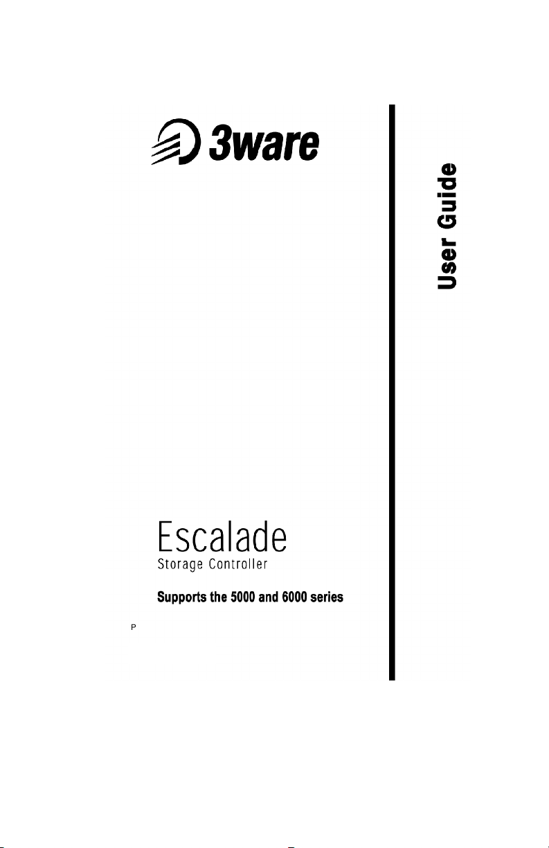
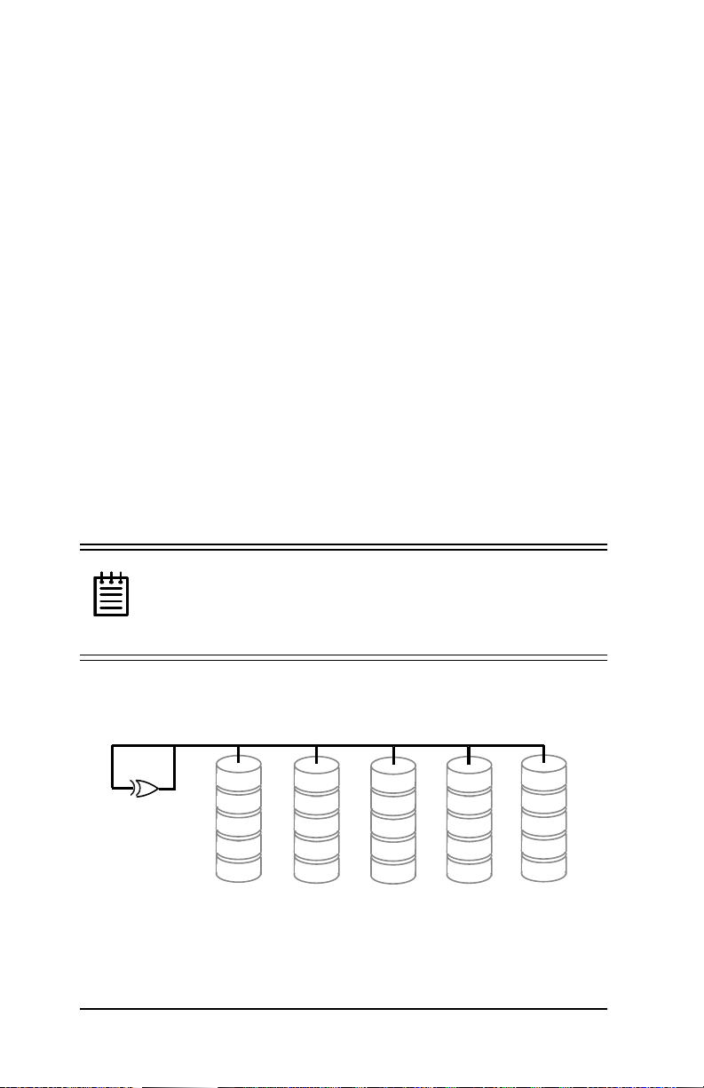
RAID 0 arrays maximize performance and capacity
When drives are configur ed in a striped disk array (see Figure 1),
the storage controller distributes large files across the multiple disks
using RAID 0 techniques. Striped disk arrays achieve high tr ansfer
rates because they can read or write data on more than one drive
simultaneously. Striped disk arrays give exceptional performance,
particularly for data intensive applications such as video editing,
computer aided design, and geographical information systems.
Striping you r disk ar ray con catena tes e ach drive’s capacity into one
large volume. The stripe size is user configurable at 64K, 128K,
256K, 512K, or 1M..
Figure 1. RAID 0 Configuration Example
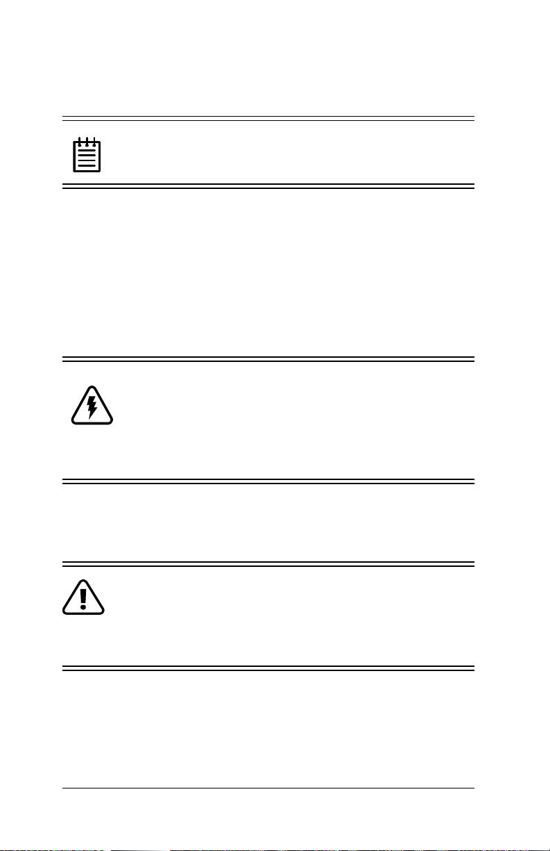
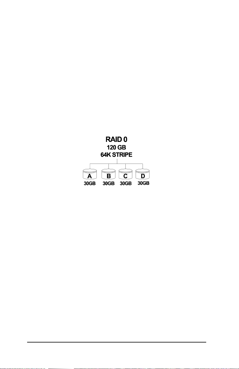
RAID 1 arrays offer fault tolerance
Mirrored disk arrays write data to two drives using RAID 1 algorithms (see Figure 2). This gives your system fault tolerance b y preserving the data on one drive if the other drive fails. Fault tolerance
is a basic requirement for mission critical systems like web and
database servers.
6 www.3ware.com
Page 19
Introduction
Figure 2. RAID 1 Configuration Example
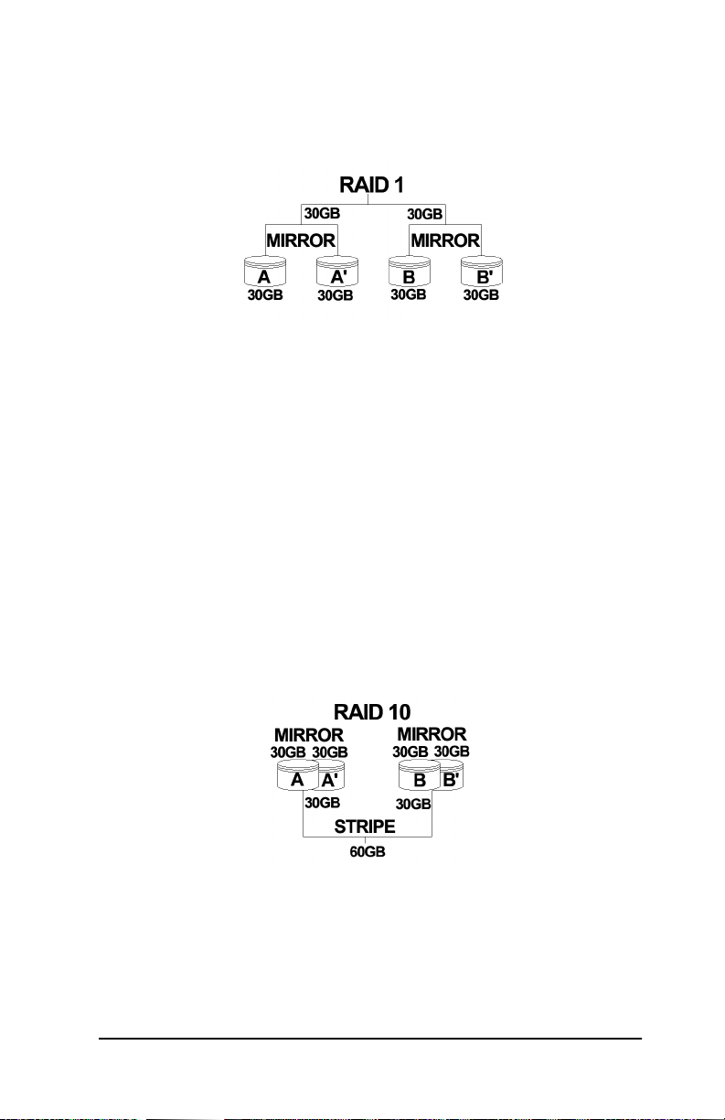
RAID 10 arrays maximize performance and fault tolerance
When drives are configured as a striped mirrored array, the disks
are configured using bot h RAID 0 and RAID 1 te chniqu es, thus the
name RAID 10 (see Figure 3). A minimum of four drives are
required to use this te chnique. The fi rst two driv es are mirror ed as a
fault tolerant array using RAID 1. The third and fourth drives are
mirrored as a second fault tolerant array using RAID 1. The two
mirrored arrays are then grouped as a striped RAID 0 array using a
two tier structure. Higher data transfer rates are achieved by leveraging TwinStor and striping (64K, 128K, 256K, 512K, or 1M) the
arrays. RAID 10 is available on the 4- and 8-port 3ware storage
controller boards.
Figure 3. RAID 10 Configuration Example
www.3ware.com 7
Page 20
3ware Storage Controller User Guide
RAID 5 arrays optimize performance, fault tolerance, high capacity, and storage efficiency
The RAID 5 configuration features the data striping of RAID 0
combined w i th the parity of RAID 4. Using a simple parity (exclusive OR) function, RAID 5 can tolera te the lo ss of one dri ve. Parity
information is distributed across all drives rather than being concentrated on a single disk (see Figure 4). This avoids throughput
loss due to contentio n for the pari ty drive. You can use hot spare s to
rebuild a failed drive “on-the-fly”.
RAID 5 capa city = size of smallest drive
× (number of drives - 1).
In addition, th e array’s storage effici ency inc reases wi th the n umber
of disks; from 66.7 % for 3 drives to 87.5 % for 8 drives: storage
efficiency = (number of drives -1)
÷ (number of drives).
Unlike all other RAID con figurations that offer data striping,
RAID 5 stripe size is limited to 64k.
1RWH%,26ZLOOUHMHFWWKHFUHDWLRQRID5$,'DUUD\
KDYLQJOHVVWKDQRUPRUHWKDQGULYHV. Also, RAID 5 is
not supported by Windows 98 or ME, or 3ware’s 5000
series storage controllers.
RAID 5
0 parity
A1
A2
A3
A4
A Blocks
B0
1 parity
B2
B3
B4
B Blocks C Blocks D Blocks
C0
C1
2 parity
C3
C4
D0
D1
D2
3 parity
D4
E0
E1
E2
E3
4 parity
E Blocks
Figure 4. RAID 5 Configuration Example
8 www.3ware.com
Page 21

Introduction
TwinStor‘ Technology adds performance to 3ware’s mirrored disk arrays
Traditional mirroring techniques do little to improve performance.
The adaptive algorithms found in 3ware’s TwinStor technology
boost performance by distinguishing between random and sequential read requests. For the sequential requests generated when
accessing large files, both drives are used, with the h eads simult aneously reading alternating sections of the file. For the smaller random transactions, the data is r ead f rom a si ngl e opt imal dri ve head.
Drives can be dynamically profiled, specifically for your brand of
drive, during installat ion to customize the stripe size (for RAID
configurations offering variable striping) and seek algorithms.
Configure and manage your disk arrays
The 3ware Disk Arr ay Conf igur ati on Ut il it y is a BIOS level tool
for creating, deleting, maintaining disk arrays, and rebuilding mirrored arrays. From the 3DM Disk Array Configuration Utility,
you can also specify hot spares from available drives to be dynamically subst ituted for a fa iled drive in a mirrored array. Refer to the
3ware Disk Array Configuration Utility chapter.
3DM Disk Management Utility is supporte d by Self-Monitoring,
Analysis, and Reporting Technology (SMART). SMART adds
monitoring and troubleshooting functionality by automatically
checking a disk drive's health and reporting potential problems. It
allows you to take proactive actions to prevent impending disk
crashes.
3DM Disk Management Utility runs in the background on the
3ware stor age controlle r’s host and allows you to monitor the storage controller and rebuild mirrored arrays remotely via a standard
web browser. To remotely access 3DM, you are not required to
install any so ftware on you r sys tem but you must h ave ac cess t o the
network with the 3ware storage controll er. 3DM supports hot spare
www.3ware.com 9
Page 22

3ware Storage Controller User Guide
and hot swap for mirrore d array s. Hot swap al lows user s to re pla ce
a failed drive in a mirrored array while the system remains up.
Refer to the 3DM Disk Management Utility chapter.
To create, delete, or verify arrays, you must use the 3ware Disk
Array Conf iguration Utility. To check array configuration or status, disable write cache, select a hot spare, or rebuild a mirrored
array, you can use the 3ware Disk Array Configuration Utility at
BIOS time or 3DM Disk Management Utility in real time. Hot
swap is only available through the 3DM Disk Management Util-
ity.
10 www.3ware.com
Page 23
Quick Install Guide
Quick Install Guide
www.3ware.com 11
Page 24

3ware Storage Controller User Guide
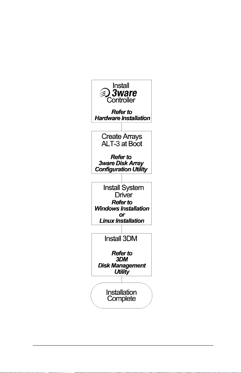
Step 1. Install the 3ware Controller
Install the 2, 4, o r, 8 port 3ware controller board i n an avai labl e PCI
slot. Slots closest to the Accelerated Graphics Port give the best
performance. The blue end of the ribbon interface cable must be
connected to the 3ware controller and the black end must be connected to the drive.
Step 2. Create Arrays
Verify your boot device precedes the 3wa re stora ge contro ller in the
boot sequence, then ALT-3 to activate the 3ware Disk Array Con-
figuration U tility at boot time. Specify RAID arrays and hot
spares.
Step 3. Install System Drivers
The 3ware controller dri vers must be i nstalle d accordin g to the type
of installation and the operating system.
Installations include:
• Installi ng the contro ller while installing the operating system.
• Installing the controll er on systems that boot from a different
device.
• Replacing an existing controller with a new version of the controller.
Operating systems supporting the 3ware controller include:
• Windows NT 4.0
• Windows 98 SE or Me, except RAID 5 configurations
• Windows 2000
• Red Hat Linux 6.1, 6.2 or 7.0
• SuSE Linux 6.3 or 6.4
12 www.3ware.com
Page 25

Quick Install Guide
Step 4. Install 3DM
Install 3DM for Windows or Linux from the 3DM installation CDROM.
:LQGRZV
a:\setup from Run... in the Start menu.
/LQX[
mount -t msdos /dev/fd0 /mnt
cd /mnt
./install.3dm
Answer questions concerning email notification and the port number for WEB monitoring.
cd /
umount /mnt
www.3ware.com 13
Page 26

3ware Storage Controller User Guide
14 www.3ware.com
Page 27
+DUGZDUH,QVWDOODWLRQ
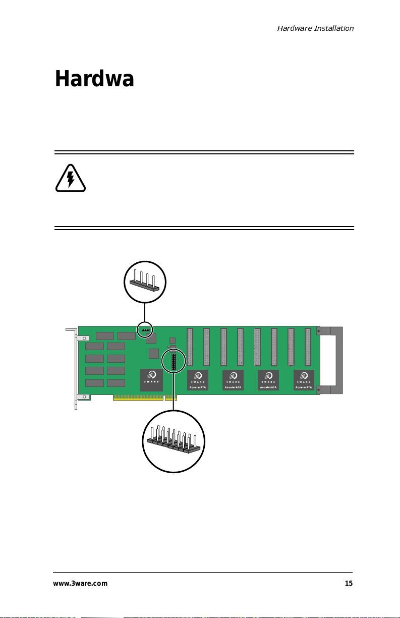
Hardware Installation
Figure 5 shows ports and connectors on the the Escalade Storage
Controller Board.
:DUQLQJBefore proceeding with hardware installa-
tion, read the Before You Begin section comple tely
describing personal and system precautions. Failing to
do so may result in personal injury or damage to your
computer or the 3ware storage controller.
1
JP3 LED drive
status connector
DiskSwitch
Note: Pin 1 and pin 4 are 5 V
and pin 2 and pin 3 are ground.
Plug cable to either pins 1 and 2
or pins 3 and 4.
Port 0 1 2 3 4 5 6 7
For manufacturing
use only
)LJXUH ZDUH3RUW6WRUDJH&RQWUROOHU
$VVHPEO\'UDZLQJ
www.3ware.com 15
Page 28

3ware Storage Controller User Guide
To remove an existing 3ware card
1 Unplug the machine from its power source before removing or
installing any hardwa re.
2 Disconnect the disks from the existing 3ware card installed in
your system. If your boot disk is connected to the card and you
intend to retain it as your boot device, note or mark which physical disk is connected to slo t 0 on the board. This disk should be
reconnected to slot 0 on the new version of the card. Preserving
the slot order of how the other drives are connected is unimportant, even if the disks are part of a disk array, although it is recommended that a plug-to-plug replacement is followed.
3 Remove the sc rew in t he metal b racket at the end of the old c ard.
Save the screw for installing the new card.
4 Gently remove the card from the PCI slot.
5 Remove the cables from the ca rd, and set it aside.
Connect the interface cables to the controller
1 Connect the interface cables supplied with the pr oduct to the
board.
2 One edge of each interface cable should have a colored (usually
red) line denoting the conduct or to Pi n 1. Align the connect or so
that the colored line is toward the top edge of the board. Mate
the connectors carefully without bending any pins.
1RWHUltra ATA/66 drives require 40-pin, 80- con-
ductor ribbon cables. These cables have color coded
ends. The blue end must be connected to the 3ware stor age controller and the black end must be connect ed to
the hard drive or performance will be degraded.
3 Install the other connectors in the same manner.
16 www.3ware.com
Page 29
+DUGZDUH,QVWDOODWLRQ
Install the control ler card in the computer
1 If the computer is running, shut it down. Turn off power to the
computer and disconnect the power cord from the outlet.
2 Open the compute r case ac cord ing to th e manufact urer’s instruc-
tions.
3 Find the PCI slot you want to use for the storage controller
board.
+LQWCable routing may be easier if you install the
board next to an open slot.
4 Remove the metal filler bracket for the slot. Save this screw; it
will be used to secure the card after you have seated it.
+LQWWhile the storage controller runs p roperly in any
PCI slot, not all slots give equal performance due to the
architecture of the PCI bus. In our laboratories, w e have
noticed that the slots cl osest to th e Accelerat ed Graphics
Port (AGP) typically give the best performance.
5 Line the ca rd up so that all pins make proper contact with the
PCI slot pins when pushed into place. The black end rail, opposite the me tal bracket, may be removed if needed to fit the card
inside the chassis. The short 4-po rt storage controller card is
keyed to ensure proper installation in a full-sized PCI slot.
6 Ensure that the contacts will mate with both grooves in the slot.
Press down gently on t he edge of th e card direc tly a bove the s lot
until the card is fully seated.
7 Verify that the card ’s metal bracket fills the ho le in the case, then
secure the bracket with the screw that was formerly used to
secure the chassis’ filler bracket.
www.3ware.com 17
Page 30

3ware Storage Controller User Guide
Connect the drives to the interface cables
1 Be sure to use the supplied cables. With the higher speeds of
Ultra ATA/66 and Ultra ATA/33, using quality cables is important.
2 Before connecting your drives, check your drives’ jumper set-
ting. The range of settings provided vary by manufacturer as do
the method for adjusting them. Refer to information provided
with your drives for the me th od re qui red to set them. To oper ate
properly, the storage controller require s th at dri ves be set as Sin-
gle (if available on your drive) or Master otherwise.
3 If your d rives ar e not al ready ins talled i nto the computer ch assis,
do so now. Be sure that the drives are connected to the power
supply. Y-splitter power supply connectors are included in some
kits in case you need additional power supply connections.
4 For each drive, select a black end of an interface ca ble not con-
nected to the board an d plug it into the drive. The ca ble’s colored
edge denoting Pin 1 should be adjacent to the 4-pin power plug.
Check your installation and close the case
1 After all of the drives ar e connected t o the storage controlle r and
the card is i nstalled in it s slot, verify that the cable s do not interfere with the operation of any other components in the case or
block the flow of cooling air.
2 Close the ca se and reconnect the power cables.
Check motherboard boot sequence
Using your computer’s Setup utility, ensure that your boot device
precedes the 3ware storage controller in the boot sequence. If you
have other disks installed on the mother board, the storage controller precedes them in boot order.
18 www.3ware.com
Page 31

3ware Disk Array Configuration Utility
3ware Disk Array
Configuration Utility
The 3ware Disk Array Configuration Utility allows you to create
disk arrays by combining disks, deleting disks or breaking disk
arrays back into their me mber disks. You can also specify an available drive as a hot spare. If an array becomes degraded, the hot
spare will automatically be substituted for the faulted drive.
1RWHIf no drives are attached to the storage cont roller
the BIOS wi ll not be insta lled. The storage controller
shares one IRQ on the PCI bus.
Invoking the 3ware BIOS tool
Reboot your system. During the boot phase, wait until you see a
message sim ilar to the fol lowing:
3ware Storage Controller BIOS X.xx
Port 0 QUANTUM FIREBALLP LM30 30.0 GB
Port 1 QUANTUM FIREBALLP LM30 30.0 GB
Port 2 QUANTUM FIREBALLP LM30 30.0 GB
Port 3 QUANTUM FIREBALLP LM30 30.0 GB
... Press <Alt-3> to access 3ware Configuration Screen ...
Press ALT-3 immediately to bring up the 3ware Disk Array Con-
figuration display.
www.3ware.com 19
Page 32

3ware Storage Controller User Guide
Exiting the 3ware BIOS tool
T o save y our config uration modi ficati ons, hit t he F8 key. After you
have hit the F8 key to commit yo ur changes , a li st of af fect ed drive s
will be displayed and you will be asked to confirm your configuration. The booting process will resume. If you have selected mirrored arrays, after the operating system is running, the sto r age
controller board will automatically run a background initialization
to verify that both disks in the arrays are identical.
To exit the 3ware Disk Array Configuration Utility without saving
your changes, hit ESC.
Determining your configuration
&DXWLRQConfiguring a disk array writes format- type
data onto it s member disk s and overwrites all the files
on those disks. Back up data that requires retention.
With a 2 port 3ware storage controller you are limited to a twodrive JBOD (Just a Bunch of Disks) or a single two-drive array.
With a 4 port 3ware storage controller, you can combine from two
to four disks into a single array. With four disks, you can create a
four drive RAID 0 array, two RAID 1 arrays, one RAID 5 array, or
one RAID 10 array.
Using the 8 port 3ware storage controller, the 4 port configuration
can be duplicated. In addition, you may also create a five, six,
seven, or eight drive RAID 0 or RAID 5 array.
1RWH3ware’s 5000 series storage controllers do not
support RAID 5 configurations.
20 www.3ware.com
Page 33

3ware Disk Array Configuration Utility
The 3ware Disk Arra y Configur ation main displa y shows the current disk drive configur ation.
• Available Drives reports independent drives (JBOD), not asso-
ciated wit h an array.
• Disk Arrays lists any existing arrays al ong with their member
disks and hot spares.
3ware Disk Array Configuration
Available Drives:
Disk Arrays:
Array Unit 0 - Mirror 30.0GB
Port 0 - QUANTUM FIREBALLP LM30 30.0GB
Port 1 - QUANTUM FIREBALLP LM30 30.0GB
Array Unit 2 - Mirror 30.0GB
Port 2 - QUANTUM FIREBALLP LM30 30.0GB
Port 3 - QUANTUM FIREBALLP LM30 30.0GB
Create Array
Help
F1
Restore Initial Values
F6
Delete Array
Previous/Next
Maintain Array
$
Toggle Hot Spare
Esc
Cancel
Rebuild Array
Enter
Select/Deselect
F8
Done
Figure 6. Disk Array Configuration Main Display, RAID 1
Example Shown
Throughout the utility (see Figure 6), use the Up and Down arrow
keys to navigate, Enter to select the disks or buttons, and F1 for
context sensitive help. Toggle Hot Spare verbiage is black when
the cursor is over a drive that can be sp ecified as a hot spare and
gray when hot spare cannot be specified. If you’ve made mistakes
and want to start over, F6 will return your starting values. Escape
will exit the configuration utility as well as abandon your changes.
F8 will save your changes and exit the utility.
www.3ware.com 21
Page 34

3ware Storage Controller User Guide
Creating a disk array
To create an array, first select the drives to be included by nav igating the cursor over each drive and pressing Enter. (See Figure 7.)
An asterisk in the left most column indicates the drive is selected.
You may include from two to eight drives in the array by selecting
drives from the A vailable Dri ves section. To include drives that are
part of an existing disk array, you must delete that array first.
3ware Disk Array Configuration
Available Drives:
*Port 0 - QUANTUM FIREBALLP LM30 30.0GB
*Port 1 - QUANTUM FIREBALLP LM30 30.0GB
Port 2 - QUANTUM FIREBALLP LM30 30.0GB
Port 3 - QUANTUM FIREBALLP LM30 30.0GB
Disk Arrays:
Create Array
Help
F1
Restore Initial Values
F6
Delete Array
Previous/Next
Maintain Array
$
Toggle Hot Spare
Esc
Cancel
Rebuild Array
Enter
Select/Deselect
F8
Done
Figure 7. Selecting Drives for a Mirrored Array
+LQW
To maximize disk space, include only drives of
equal capacity. The capacity of each drive is limited to
the capaci ty of the smallest drive in the array. The array
must also be configured only with equivalent drives.
total capacity of the array = (number of drives in the array) X
22 www.3ware.com
(capacity of smallest drive in the array)
Page 35

3ware Disk Array Configuration Utility
After selecting all the drives for the array, navigate to the Create
Array button. Hit Enter to bring up the Create Disk Array dis-
play (see Figure 8 and Figure 9 for examples). Check that the
proper drives are listed.
Create Disk Array
Note: Creating an array will overwrite existing data on its drives.
Create a disk array from these drives:
Port 0 - QUANTUM FIREBALLP LM30 30.0GB
Port 1 - QUANTUM FIREBALLP LM30 30.0GB
Select RAID Configuration:
Array's Write Cache State:
OK
Stripe (RAID 0)
enable
OK
Stripe Size:
Cancel
64 KB
120KB
250KB
512KB
1mb
HelpF1
Previous/Next
Change ValueEnter
CancelEsc
Figure 8. Create Disk Array Display, RAID 0 Example
www.3ware.com 23
Page 36

3ware Storage Controller User Guide
Create Disk Array
Note:Creating an array will overwrite existing data on its drives.
Create a disk array from these drives:
Port 1 - IBM-DTLA-387815 512 M
Port 2 - IBM-DTLA-387815 512 M
Port 3 - IBM-DTLA-387815 512 M
Select RAID Configuration:
Array's Write Cache State:
HelpF1
Previous/Next
OK
RAID 5
enable
Stripe Size:
Cancel
Change ValueEnter
64 KB
CancelEsc
Figure 9. Create Disk Array Display, RAID 5 Example
Select RAID configuration
The 3ware storage controllers give you a choice of four RAID configurations. Select one.
• Stripe (RAID 0): maximizes performance and capacity through
a process called striping . High performance arrays writ e portions
of a single file across multiple drives. There is no fault tolerance.
• Mirror (RAID 1): duplicate or “mirror” the data on both drives.
No data will be lost if one of the drives fails.
• RAID 10: combine mirroring and striping, providing both fault
tolerance and high performance. RAID 10 arrays use a mini-
mum of four drives. Configurations consist of 4, 6, or 8 drives.
• RAID 5: combines parity data and st ripi ng, provi ding fau lt tol erance, high capacity, and high storage efficiency. The parity data
is distributed acr oss al l dr ive s, rather th an be ing con centr ate d on
a single disk, to avoid throughput loss due to corrections for the
24 www.3ware.com
Page 37

3ware Disk Array Configuration Utility
parity drive. RAID 5 arrays requre a minimum of three
drives and are not supported by 3ware’s 5000 series storage
controllers. Configurations consist of 3, 4, 5, 6, 7, or 8 drives.
For RAID 5 Array, initialize using BIOS
Because of the Read-Modi fy-Write operations, you must fi rs t write
zeros to all drives in the array before the array is functional. The
screen, shown in Figure 10, appears after selecting Create Array.
If the write-zeros operation is aborted by the user for any reason,
the unit will go into initializing mode when restarte d. Initializing
scans the entire array to verify the parity. If coherency problems
appear, the parity will be corrected to match the data found on that
stripe.
&DXWLRQ:KHQUXQQLQJLQLQLWLDOL]LQJPRGHWKHDUUD\
LVQRWUHGXQGDQW<RXFDQQRWUHPRYHDQ\GULYH
www.3ware.com 25
Page 38

3ware Storage Controller User Guide
3ware Disk Array Configuration
Available Drives:
Port 0 - QUANTUM FIREBALLP KX27.3 512 M
Disk Arrays:
Array Unit 1 - 3 drive 64K RAID 5 1.0 GB
Port 1 - IBM-DTLA
Port 2 - IBM-DTLA
Port 3 - IBM-DTLA
Init RAID5 Array Unit 1
Percentage done : 25%
Create Array
Help
F1
Restore Initial Values
F6
Delete Array
Previous/Next
Maintain Array
$
Toggle Hot Spare
Esc
Cancel
Rebuild Array
Enter
Select/Deselect
F8
Done
Figure 10. BIOS Initialization Screen for RAID 5
Select striping size
For a RAID 1 or RAID 10 configuration, select the striping size.
Sizes of 64K, 128K, 256K, 512K, or 1M are selected using the
Strip Size box, shown in Figure 8. RAID 5 only allows a 64K
stripe size.
Select write cache properties
The 3ware storage controllers give you a choice of disabling the
write cache for your disk arrays. Write cache is used to store data
locally on the drive before it is written to the disk, allowing the
computer to continue with its next task. Enabling the write cache
results in the most efficient access times for your co mpute r s y st em.
There may be instances, however, when you always want the computer to wait for the drive to write all the data to disk be fore going
on to its next task. For this case, you must disable the write cache.
26 www.3ware.com
Page 39

3ware Disk Array Configuration Utility
To disable the write cache, select not in use from the array’s Write
Cache State selection. Th e default for Write Cache State is in
use.
Confirm array configuration
Select the OK button to confirm creating the array, or Cancel to
reject it. The array is not actually created and no data will be overwritten until you have finished making all your changes and select
the F8 key.
Specifying a hot spare
3ware storage controll ers give you the option to specify a hot spare
from one of your Available Drives. If a hot spare is specified and
the mirror degrad es, an event n otificati on will be gen erated. The hot
spare will dynamically replace the failed drive in a mirrored array
without user intervention. Select a hot spar e by navigating to an
Available Drive. The Toggle Hot Spare verbiage at the bottom of
the screen will be black if the drive can be used as a hot spare.
Enter S to select the hot spare.
1RWHHot spare drives need to have the same or larger
storage capacity than the Raid 1 or Raid 10 drives.
Changing an existing configuration
1 Back up any disk arra ys that cont ain dat a that you want to retain
before the configuration change.
2 Create new disk arrays follo wing the instructions in the Deter-
mining your configuration, Creating a disk array, and Deleting a disk array sections. Note that you may need to delete
existing arrays to free u p disks first.
www.3ware.com 27
Page 40

3ware Storage Controller User Guide
3 Partition and format any new disk arrays and free disk.
4 When you are fi nished configuring, restore from backup any
data saved from previous disk arrays
Modifying a disk array
T o modify an existing array, you must first delete it, then re-create it
with the new drives. As with all dis k array operations, there is no
way to modify an existing array without overwriting data on the
drives involved.
Deleting a disk array
To delete an array (see Figure 11), first select the array by navigating to it and hitting Enter. An asterisk in the left most column indi-
cates the array is selected.
3ware Disk Array Configuration
Available Drives:
Disk Arrays:
*Array Unit 0 - Stripe 64K 120.0GB
Port 0 - QUANTUM FIREBALLP LM30 30.0GB
Port 1 - QUANTUM FIREBALLP LM30 30.0GB
Port 2 - QUANTUM FIREBALLP LM30 30.0GB
Port 3 - QUANTUM FIREBALLP LM30 30.0GB
Create Array
Help
F1
Restore Initial Values
F6
Delete Array
Previous/Next
Maintain Array
$
Toggle Hot Spare
Esc
Cancel
Rebuild Array
Enter
Select/Deselect
F8
Done
Figure 11. Delete Disk Array Display
28 www.3ware.com
Page 41

3ware Disk Array Configuration Utility
Navigate to the Delete Array button and hit Enter to bring up the
Delete Disk Array display. Check that the correct drives are listed.
Select the OK key to confir m delet ing the arra y, or Cancel to reject
it. Recall that the array is not actually deleted and no data will be
overwritten until you have finished making all your changes and
selected the F8 key.
How to maintain or verify a disk array
The Maintain Disk Array display (see Figure 12) shows the current disk array configurations that you have selected. Write Cache
State can be changed. Refer to Select write cache properties paragraph in the Cr eati ng a dis k ar ray. V e rify Ar ray can be s pecif ied
as no or yes. The default is no. Yes launches a foreground process
that compares the two drives of a Raid 1 or Raid 10 (m irrored)
array, sector by sector. If the verify array process determines that
the drives are not identical, the mirror is degraded and the rebuild
process is launched.
www.3ware.com 29
Page 42

3ware Storage Controller User Guide
Maintain Disk Array
The array listed below can have its write cache state changed.
Verify checks the data integrity of a fault tolerant array.
Array Unit 2 - Mirror 30.0GB
Port 2 - QUANTUM FIREBALLP LM30 30.0GB
Port 3 - QUANTUM FIREBALLP LM30 30.0GB
OK
in use
no
Cancel
Change ValueEnter
Write Cache State:
Verify Array:
HelpF1
Previous/Next
Figure 12. Maintain Disk Array Display
CancelEsc
30 www.3ware.com
Page 43

3ware Disk Array Configuration Utility
Rebuilding a mirrored disk array
3ware storage controllers allow you to create fault tolerant disk
arrays by selecting a mirrored RAID 1 or RAID 10 array. These
disk arrays store identical data on two or more drives to protect
against drive failur e. If one or more of the drive s of a mirrored arr ay
is removed, unplugged, or fails on read or write requests, the array
is marked as DEGRADED and the drive is marked as Not In Use.
(See Figure 13 and Figure 14.)
You can still read and writ e dat a fro m a de graded disk a rray, but the
array will not be fault tolerant until it is rebuilt using the Rebuild
feature, described in the 3ware Disk Array Configuration Utility or
3DM Disk Management Utility chapters.
3ware Disk Array Configuration
Available Drives:
Port 2 - QUANTUM FIREBALLP LM30 30.0GB
Port 3 - QUANTUM FIREBALLP LM30 30.0GB
Disk Arrays:
Array Unit 0 - Mirror 30.0GB DEGRADED
Port 0 - QUANTUM FIREBALLP LM30 30.0GB Not in Use
Port 1 - QUANTUM FIREBALLP LM30 30.0GB
Create Array
Help
F1
Restore Initial Values
F6
Delete Array
Previous/Next
Maintain Array
$
Toggle Hot Spare
Esc
Cancel
Rebuild Array
Enter
Select/Deselect
F8
Done
Figure 13. Degraded RAID 1 Array Drive When Not in Use
www.3ware.com 31
Page 44

3ware Storage Controller User Guide
3ware Disk Array Configuration
Available Drives:
Disk Arrays:
Array Unit 0 - RAID 10 60.0GB DEGRADED
Port 0 - QUANTUM FIREBALLP LM30 30.0GB Not in Use
Port 1 - QUANTUM FIREBALLP LM30 30.0GB
Port 2 - QUANTUM FIREBALLP LM30 30.0GB
Port 3 - QUANTUM FIREBALLP LM30 30.0GB
Create Array
Help
F1
Restore Initial Values
F6
Delete Array
Previous/Next
Maintain Array
$
Toggle Hot Spare
Esc
Cancel
Rebuild Array
Enter
Select/Deselect
F8
Done
Figure 14. Degraded RAID 10 Array Drive When Not in Use
1RWH
A RAID 10 array can be configured with either
4, 6, or 8 disks. In a 4-dr ive configuration, up to two
drives can be rebuilt. In a 6-drive configuration, up to
three drives can be rebuilt. In an 8-drive configuration,
up to four drives can be rebuilt.
32 www.3ware.com
Page 45

3ware Disk Array Configuration Utility
Rebuilding a RAID 5 disk array
3ware stora ge controllers allow you to create fault tol erant RAID 5
disk arrays. These disk arrays achieve fault tolerance by using a
simple (exclusive OR) function to generate the parity data that is
distributed on al l drive s. If one of the drives is re moved, unplu gged,
or fails on read or write requests, the array is marked as
DEGRADED and the drive is marked as Not In Use. (See
Figure 15.) When running in Degraded mode, the missing data is
reconstructed from all non-degraded drives.
3ware Disk Array Configuration
Available Drives:
Port 0 - QUANTUM FIREBALLP KX27.3 512 M
Disk Arrays:
Array Unit 1 - 3 drive 64K RAID 5 1.0GB DEGRADED
Port 1 - IBM-DTLA-387815 512 M
Port 2 - IBM-DTLA-387815 512 M Not in Use
Port 3 - IBM-DTLA-387815 512 M
Create Array
Help
F1
Restore Initial Values
F6
Delete Array
Previous/Next
Maintain Array
$
Toggle Hot Spare
Esc
Cancel
Rebuild Array
Enter
Select/Deselect
F8
Done
Figure 15. Degraded RAID 5 Array Drive When Not in Use
As in the case of RAID 1 and 10 arrays, RAID 5 arrays allow you to
read and write data from a degraded disk array, but the array will
not be fault tolerant until it is rebuilt using the Rebuild feature,
described in the 3ware Disk Array Configuration Utility or 3DM
Disk Management Utility chapters.
www.3ware.com 33
Page 46

3ware Storage Controller User Guide
Rebuilding a mirrored or RAID 5 array with no hot spare
1 Reboot the system and enter the Disk Array Configuration
Utility.
2 If your mirrored or RAID 5 array has a Not in Use member
drive, the drive may still be usable. Try rebuilding with the Not
in Use drive intact. Simply select the array and then the Rebuild
button.
3 Confirm that you selected the correct array by hitting OK in the
Rebuild confirmation display.
4 Select F8 to exit the Disk Array Configuration Utility. The
array will begin rebui lding a fter complet ion of t he oper ating system load.
5 If the rebuild fails and you have no Available Drives, you must
replace the drive and restart the rebuild process with the new
drive. If the rebuild process fails and you have Available
Drives, reboot the system and enter the Disk Array Configura-
tion Utility.
34 www.3ware.com
Page 47

3ware Disk Array Configuration Utility
6 Select an available drive to replace the faulted drive in the array
by navigating the cursor over the available drive and hitting
Enter. (See Figure 16.) An asterisk in the left most column indicates the drive is selected.
3ware Disk Array Configuration
Available Drives:
Port 2 - QUANTUM FIREBALLP LM30 30.0GB
*Port 3 - QUANTUM FIREBALLP LM30 30.0GB
Disk Arrays:
*Array Unit 1 - Mirror 30.0GB DEGRADED
Port 1 - QUANTUM FIREBALLP LM30 30.0GB
Create Array
Help
F1
Restore Initial Values
F6
Delete Array
Previous/Next
Maintain Array
$
Toggle Hot Spare
Esc
Cancel
Rebuild Array
Enter
Select/Deselect
F8
Done
Figure 16. Select Available Drive to Replace Faulted Drive,
RAID 1 Example
www.3ware.com 35
Page 48

3ware Storage Controller User Guide
7 Navigate to the Rebuild Array button and press Enter (see
Figure 17). A status screen will be displayed with your
requested array and member drives.
3ware Disk Array Configuration
Available Drives:
Port 2 - QUANTUM FIREBALLP LM30 30.0GB
Disk Arrays:
Array Unit 1 - Mirror 30.0GB REBUILDING (after F8)
Port 1 - QUANTUM FIREBALLP LM30 30.0GB
Port 3 - QUANTUM FIREBALLP LM30 30.0GB
Create Array
Help
F1
Restore Initial Values
F6
Delete Array
Previous/Next
Maintain Array
$
Toggle Hot Spare
Esc
Cancel
Rebuild Array
Enter
Select/Deselect
F8
Done
Figure 17. Rebuild Array Status Display, RAID 1 Example
36 www.3ware.com
Page 49

3ware Disk Array Configuration Utility
8 Press F8 to rebuild. The rebuild confirmati on sc reen will be dis-
played (see Figure 18).
3ware Disk Array Configuration
Creating or destroying arrays will destroy all existing data on their
member disk drives.
Data on the following drives will be destroyed.
Port 3 QUANTUM FIREBALL LM30
Also, Array Unit 1 will be rebuilt by copying data
from Port 1 QUANTUM FIREBALL LM3...to Port 3 QUANTUM FIREBALL LM3
Update configuration and exit? [Y/N]
Restore Initial ValuesF6
CancelEsc
DoneF8
Figure 18. Rebuild Confirmation Display
9Enter Y to update configurations and exit.
Auto rebuild of a mirrored or RAID 5 array
If a hot spare is specified and the mirrored or RAID 5 array
degrades, an event notification is generated and the hot spare
dynamically replaces the failed drive in the array without user intervention. Rebuild wil l automat ical ly be la unched a s backgr oun d process and an event notification will notify the user when the rebuild
process is complete.
www.3ware.com 37
Page 50

3ware Storage Controller User Guide
Auto rebuild on power failure
During dri ver startup, 3ware’s auto rebuild feature sets a flag indicating that th e dri ver l oaded. Upon an order ly shu tdown, t he fl ag is
rewritten, indicating a clean shutdown. During the next system
power cycle, the firmware queries the flag. For a RAID 1 configuration, if there was a probl em, th e firmware de grades the sec ondary
drive in the array and starts the background rebuild of the mirrored
drive. When t he rebuild is complete, the tw o halves of the m irror
will be resynchronized. For a RAID 5 configuration, if there is a
problem, the firmware starts the background verification that
checks that the parity matches the data.
38 www.3ware.com
Page 51

Windows Installation
Windows Installation
Note: If you haven’t yet installed the hardware, retur n
to the Hardware Installati on section. The hardware
must be installed before you can configure the 3ware
storage controller.
Windows NT 4.0 Installation . . . . . . . . . . . . . . . . . page 40
Windows 98/Me Installation . . . . . . . . . . . . . . . . . page 57
Windows 2000 Installation . . . . . . . . . . . . . . . . . . page 73
www.3ware.com 39
Page 52

3ware Storage Controller User Guide
Windows NT®4.0 Installation
The 3ware storage c ontroller may be configured t o be your syst em’s
boot device, or you can us e another device, such as a disk attached
to the motherboard as your boot device. Use your system’s Setup
utility to set the boot order according to how you install your operating syste m.
If Windows NT has not been installed on the system, follow the
instructions in either of the following sections (note: use of a boot
floppy diskette may be required by some systems):
Installing the controller and Windows NT 4.0 (page 41).
Installing the controller and Windows NT 4.0 when using the
boot diskettes (page 45).
If you are installing the storage controller on a s ystem that al ready
has Windows NT installed on a drive connected to another storage
controller, follow the instructi ons in:
Installing the controller on systems that boot from a different
device (page 49).
If you are replacing an installed 3ware storage controller with a
newer 3ware storage cont roller, follow the instructions in
Replacing an existing controller with a new version of the controller (page 51).
Note: Windo ws NT 4.0 driver requires Se rvice Pack 4 or
later. Also, you cannot install the driver or the operating
system unless y ou have admin istr ator privi leges for y our
system.
40 www.3ware.com
Page 53

Windows NT®4.0 Installation
Installing the controller and Windows NT 4.0
Materials required:
• Windows NT 4.0 installati on CD-ROM
• 3ware CD-ROM
• 3ware Windows driver installation diskette
Has your boot drive been partitioned?
Microsoft Windows NT 4.0 Setup occasionally has problems
installing on drive s that hav e not bee n partit ioned. If y ou are havi ng
trouble, you may need to cr eate a partition on the drive where you
plan to install Windows NT 4.0.
1Use the FDISK DOS utility to get your disk partitioned and
ready for installation quickly:
2 Boot MS-DOS and use FDISK to create a partition on the boot
drive. The partition does not need to be formatted or made
active. Wit h FDISK you are limited to 4 GB for your boot partition. If you need a larger boot space, create a single small (e.g.,
100 MB) partition, then adjust the size during Windows NT 4.0
Setup.
Boot the system
Insert the Windows NT 4.0 CD-ROM into the CD-ROM drive.
Create disk arrays
Refer to the 3ware Disk Array Configuration Utility chapter.
Continue with Windows NT 4.0 installation
1 When Setup is Inspecting Your Computer Hardware Config-
uration is displayed, press F6 immediately.
2 You will see a Windows NT 4.0 Setup display.
www.3ware.com 41
Page 54

3ware Storage Controller User Guide
3 Press S to specify that you will be installing an additional mass
storage device. On the display that follows, select Other and
press Enter.
Install the driver using the 3ware diskette
1 You will be asked to insert a manufacturer-supplied hardware
support disk. Insert the 3ware Windows driver installation diskette into the floppy drive and pr ess Enter. DO NOT use the dis-
kette labeled specifically for Windows NT driver installation.
2 Select the 3ware Storage Controller from the display that
appears and press Enter again. Ensure the path to this drive r is
correct in Copy manufacturer’s files from: at the bo ttom o f the
box. To do this, type A:\winnt
3 After the driver is loaded from the diskette, you will receive the
message “Setup has recognized the following mass storage
devices in your computer:” The list will contain the 3ware Stor-
age Controller. If it does not appear, you must check the hardware and restart this software installation. Otherwise, press
Enter.
Partition device 0 to create a boot area
1 Follow the displayed instructions for Windows NT 4.0 installa-
tion as directed until the following message appears “The list
below shows existing partitions and spaces available for creating
partitions.”
2 The partit ions list s hould contain an entry for yo ur 3ware st orage
controller that resembles the following: 4111 MB Disk 0 at Id 0
on bus 0 on 3waregsm. If it does not include a 3ware entry,
check your hardware and restart the software installation process.
3 Create a partition in the unpartitioned space of device 0 for
installing Windows NT 4.0. Keep in mind that the space available in a disk array is often larger than is allowed in a single partition. Format the partition as desired with FAT or NTFS.
42 www.3ware.com
Page 55

Windows NT®4.0 Installation
Follow display instructions to complete W indows NT 4.0 installation
1 Continue with the normal Windows NT 4.0 installation.
2 Log in as administrator. You should see a brief splash screen
(see Figure 19) followed immediately by an Installation Com-
plete notification (see Figure 20).
3 Partition and format any new disk arrays or independent disks
using Disk Administrator in the remaining steps:
aFrom the Start menu, choose Programs.
bFrom the Programs menu, choose Administrative Tools.
cFrom the Administrative Tools menu, choose Disk Admin-
istrator.
Figure 19. Controller Quick-Splash Screen
Figure 20. Installation Complete Notification
www.3ware.com 43
Page 56

3ware Storage Controller User Guide
Install the 3DM disk management utility
Refer to 3DM Disk Management Utility chapter.
44 www.3ware.com
Page 57

Windows NT®4.0 Installation
Installing the controller and Windows NT 4.0 when using the boot diskettes
Materials required:
• Windows NT 4.0 boot installat ion disket tes (3)
• Windows NT 4.0 installati on CD-ROM
• 3ware Windows NT 4.0 driver installation diskette
• 3ware CD-ROM
Note: This installation proc edure uses W in dows NT 4.0
diskettes in addition to the Windows NT 4.0 CD-ROM.
Other installation methods should work, but be sure to
detect the board and to install the driver at the appropriate time.
Has your boot drive been partitioned?
Microsoft Windows NT 4.0 Setup occasionally has problems
installing on drive s that hav e not bee n partit ioned. If y ou are havi ng
trouble, you may need to cr eate a partition on the drive where you
plan to install Windows NT 4.0.
1Use the FDISK DOS utility to get your disk partitioned and
ready for installation quickly:
2 Boot MS-DOS and use FDISK to create a partition on the boot
drive. The partition does not need to be formatted or made
active. Wit h FDISK you are limited to 4 GB for your boot partition. If you need a larger boot space, create a single small (e.g.
100 MB) partition, then adjust the size during Windows NT 4.0
Setup.
Boot the system
Insert Windows NT 4.0 Setup Disk #1 into the floppy drive.
www.3ware.com 45
Page 58

3ware Storage Controller User Guide
Create disk arrays
Refer to 3ware Disk Array Configuration Utility chapter.
Continue with Windows NT 4.0 inst allation
Insert the other dis kettes into t he floppy drive as requested unti l you
get to the Welcome to Setup display.
1 When the Welcome to Setup display appears, Press Enter to
begin the setup process. You will be asked whether you want to
detect ma ss storage devices. Sig nify “yes” by pressing Enter.
2 Insert any othe r Windows NT 4.0 diskettes into the floppy drive
as requested until you get to Setup has recognized the follow-
ing mass storages devices. This indic ates that mas s storage
device detection is complete.
3 Press S to specify that you will be installing an additional mass
storage device. On the display that follows, select Other and
press Enter.
Install the driver using the 3ware diskette
1 You will be asked to insert a manufacturer-supplied hardware
support disk. You MUST use the diskette labeled as the 3ware
Windows NT drive r installation diskette for this step. Insert the
diskette into the floppy drive and press Enter.
2 Select the 3ware Storage Controller from the displa y that
appears and press Enter again.
3 After the driver is loaded from the diskette, you will receive the
message “Setup has recognized the following mass storage
devices in your computer:” The list will contain the 3ware Stor-
age Controller. If it does not appear, you must check the hardware and restart this software installation. Otherwise, press
Enter.
46 www.3ware.com
Page 59

Windows NT®4.0 Installation
Partition device 0 to create a boot area
1 Follow the displayed instructions for Windows NT 4.0 installa-
tion as directed until you are shown: “The list below shows
existing partitions and spaces available for creating partitions.”
2 The partit ions list s hould contain an entry for yo ur 3ware st orage
controller that resembles the following: 4111 MB Disk 0 at Id 0
on bus 0 on 3waregsm. If it does not include a 3ware entry,
check your hardware and restart the software installation process.
3 Create a partition in the unpartitioned space of device 0 for
installing Windows NT 4.0. Keep in mind that the space available in a disk array is often larger than is allowed in a single partition. Format the partition as desired with FAT or NTFS.
4 Insert the Windows NT 4.0 installation CD-ROM and continue
to the next section.
Follow display instructions to complete W indows NT 4.0 installation
1 Continue with the normal Windows NT 4.0 installation.
2 Log in at the administrator le vel and wait for the system to
reboot.
3 Insert the 3ware Windows NT 4.0 driver installation diskette.
4 Select Start then Run. In the dialog box that appears, type:
A:\setup.exe
5 Press OK. A brief splash screen (Figure 19) appears, follow ed
immediately by an Installation Comp lete notification
(Figure 20).
6 Partition and format any new disk arrays or independent disks
using Disk Administrator in the remaining steps:
aFrom the Start menu, choose Programs.
bFrom the Programs menu, choose Administrative Tools.
www.3ware.com 47
Page 60

3ware Storage Controller User Guide
cFrom Administrative Tools, choose Disk Administrator.
48 www.3ware.com
Page 61

Windows NT®4.0 Installation
Installing the controller on systems that boot from a different device
Materials required:
• 3ware Windows driver installation diskette
• 3ware CD-ROM
Create disk arrays
Refer to 3ware Disk Array Configuration Utility chapter.
Install the 3ware driver
1 When the system finishes booting, log in as system administra-
tor.
2 Go to the Start menu, click on Settings, and open the Control
Panel window.
3From the Control Panel windo w, open SCSI Adapters.
4 Click on the Drivers tab in SCSI Adapters.
5 Follow the instructions in the Install/Update 3ware driver sec-
tion (page 52) to continue.
Reboot the machine
1 Remove the drive r dis kette , then s elect Yes to restart the system.
If you don’t remove the diskette, the system may not boot.
2 Log in as system administrator. You should see a brief splash
screen (see Figure 19) followed immediately by an Installation
Complete notification (see Figure 20).
3 Partition and format any new disk arrays or independent disks
using Disk Administrator in the remaining steps:
aFrom the Start menu, choose Programs.
bFrom the Programs menu, choose Administrative Tools.
cFrom the Administrative Tools menu, choose Disk Admin-
istrator.
www.3ware.com 49
Page 62

3ware Storage Controller User Guide
Install the 3DM disk management utility
Refer to 3DM Disk Management Utility chapter.
50 www.3ware.com
Page 63

Windows NT®4.0 Installation
Replacing an existing controller with a new version of the controller
Caution: Install the new version of the driver before
installing the new controller board. Your computer system will not boot with the new version of the controller
unless the new version of the driver has been installed
first.
Note: Upgrading to a new version of the 3ware storage
controller does not require reconfiguring the drives connected to your controller and will not affect data stored
in your disk arrays for this and previous versions.
Update the 3ware driver
1 Log in to your system as system administ rator.
2 Go to the Start menu, click on Settings, and open the Control
Panel window.
3From the Control Panel windo w, open SCSI Adapters.
4 Click on the Drivers tab in SCSI Adapters.
5 Click on the Remove button to remov e the current driver. (See
Figure 21.)
6 Follow the instructions in the Install/Update 3ware driver sec-
tion (page 52) to continue.
www.3ware.com 51
Page 64

3ware Storage Controller User Guide
Figure 21. Remove Current Driver
Install/Update the 3ware driver
1Click on the Add… button. (See Figure 21.) The Install Driver
dialog appears. (See Figure 22.)
52 www.3ware.com
Page 65

Windows NT®4.0 Installation
Figure 22. Install Driver
2 Click on the Have Disk… button. The Install from Disk
(Figure 23) dialog appears. Insert the 3ware driver installation
diskette. DO NOT use the special diskette labeled specifically
for Windows NT driver installation.
3 Ensure that the path name is c orrect in Copy manufacturer’s
files from: at the bottom of the box. To do this, type A:\winnt
www.3ware.com 53
Page 66

3ware Storage Controller User Guide
Figure 23. Install from Disk
4The Install Driver (Figure 24) dialog box appears. Click on the
3ware Storage Controller listed in the dialog box to highlight
it, then click on OK. Be sure to select the correct controller
listed, otherwise the driver update will not be successful. A
progress bar appears briefly, followed by a System Settings
Change dialog.
5 Shutdown your system.
54 www.3ware.com
Page 67

Windows NT®4.0 Installation
Figure 24. Install Driver
Remove the existing 3ware card and install the new 3ware card
Refer to Hardware Installation chapter.
Reboot the machine
1 Remove the driver diskette from your PC, then turn on the
power to restart your system. If you don’t remove the diskette,
the system may not boot.
2 If you choose to reconfigure your disk arrays, press ALT-3 to
bring up the Disk Array Configuration Utility.
3 Log in at the administrator le vel and wait for the system to
reboot. You should see a brief splash screen (Figure 19) fol-
www.3ware.com 55
Page 68

3ware Storage Controller User Guide
lowed immediately by an Installation Complete notification
(Figure 20).
4 Partition and format any new disk arrays or independent disks
using Disk Administrator in the remaining steps:
aFrom the Start menu, choose Programs.
bFrom the Programs menu, choose Administrative Tools.
cFrom the Administrative Tools menu, choose Disk Admin-
istrator.
56 www.3ware.com
Page 69

Windows® 98/Me Installation
Note: The procedures provided in this chapter apply to
both Windows 98 and the Millenium Edition (Windows
Me) installations. The RAID 5 configuration is not supported by Window 98 or ME.
Windows® 98/Me Installation
As a Plug-and-Play
configured to be your system’s boot device, or you can use another
device, such as a disk attached to the motherboard as your boot
device. Use your system’s Setup utility to set the boot order accord-
ing to how you install your operating system.
If you have a new drive configuration without an operating system
and want to install W indows on a drive managed by 3ware ’s storage
controller, follow the instructi ons in:
Installing the controller while installing Windows 98/Me
(page 59).
If you are installing the storage controller on a s ystem that al ready
has the operating system installed on a unit connected to another
storage controller, follow the instructions in:
Installing the controller on systems that boot from another
device (page 62).
If you are replacing an installed 3ware storage controller with a
newer versio n, follow the i nstructions in:
Replacing an existing controller with a new version of the controller (page 65).
device, the 3ware storage controller may be
www.3ware.com 57
Page 70

3ware Storage Controller User Guide
Note: Windows 98 driver requires Microsoft Windows
98 Second Edition, and th at you ca nnot install the driver
or the operating syst em unless you have administrator
privileges for your system.
58 www.3ware.com
Page 71

Windows® 98/Me Installation
Installing the controller while installing Windows 98/Me
Materials required:
• 3ware Windows driver installation diskette
• Windows 98/Me CD-ROM
• 3ware CD-ROM
Create disk arrays
Refer to 3ware Disk Array Configuration Utility chapter.
Boot the system from the Windows 98/Me diskette
1 Insert Windows 98/Me boot disk into the floppy drive.
2 Restart your computer.
3 From the Windows 98 or Me Startup Menu, choose 1. Start
computer with CD-ROM support.
Partition the boot device using fdisk
1 If your disks have not been partitioned, you will get a message
like Windows has dete cted that drive C does not contain a
valid FAT or FAT32 partition. From the MS-DOS command
prompt, run fdisk to create a partition.
A:\> fdisk
2 When asked to enable large disk support, indicate Yes by typing
Y.
3 Under FDISK Options, select option 1, Create a DOS parti-
tion or Logical DOS Drive.
4 Under Create a DOS Partition or Logical DOS Drive, select
option 1, Create a Primary DOS partition.
www.3ware.com 59
Page 72

3ware Storage Controller User Guide
5 When asked to use the maximum available size for a Primary
DOS Partition, indicate Yes by typing Y. Then, press the
Escape key to return to the FDISK Options menu.
6 After the pri mar y DOS parti ti on is crea te d for your boot devi ce ,
you may partition any other devices on your system. Select
option 5 to change the current drive, and then repeat steps 3-5.
7 Press the Escape key several times as directed to exit fdisk and
return to the MS-DOS prompt.
Restart the machine and format the boot device
1 As you did before, choose 1. Start computer with CD-ROM
support.
2 If you get the same message (e.g., Windows has detected that
drive C does not contain a valid FAT or FAT32 partition),
then your partition was not cr eate d proper ly. Return to the Partition the boot device using fdisk and try again. You may have
restarted without exiting all the way to the MS-DOS prompt.
3 At the MS-DOS prompt, format your boot device.
A:\> format C:
Continue the standard Windows 98/Me installation
1 Insert the Windows 98/Me CD-ROM into your CD-ROM drive.
2 From the MS-DOS prompt , type setup to continue with the stan-
dard Windows 98 or Me installation.
3After ScanDisk finishes, type X for exit.
4 Follow the display instructions. Note that the machine restarts
several times in the process.
5 Install the 3 ware drive r. Refer to the Install 3wa r e dr iver s ecti on.
60 www.3ware.com
Page 73

Windows® 98/Me Installation
Partition and format other devices
Note: If you have disks or disk arrays other than your
boot device on the controller, you must partition and format them before they can be written to or r ead from.
1 If you have other disk units to partition, run fdisk by selecting
Run... from the Start menu, and typing fdisk in the dialog.
2 Restart the system again and format each device.
Install the 3DM Disk Management Utility.
Refer to 3DM Disk Management Utility chapter.
www.3ware.com 61
Page 74

3ware Storage Controller User Guide
Installing the controller on systems that boot from a different device
Materials required:
• 3ware Windows driver installation diskette
• 3ware CD-ROM
Create disk arrays
Refer to 3ware Disk Array Configuration Utility chapter.
Install the 3ware driver
As a Plug-and-Play
3ware storage controller and automatically bring up the Add New
Hardware Wizard which will guide you in installing the new
3ware driver. (See Figure 25.) When the Add New Hardware Wiz-
ard screen appears, continue to the Ins tall/Update 3ware driver
section. Perform the following steps only if this Wizard does not
appear on your screen or was cancelled for some reason:
1 Log in after Windows in stallation is complete and in sert the
3ware Windows driver installation diskette.
2From the Start menu, select Setting, then Control Panel.
3 Double cli ck on Add New Hardwar e icon. When the Add New
Hardware wizard lists devices that need to be installed, select
the SCSI Controllers.
4 Continue to the Install/Update 3ware driver section.
device, Windows 98/Me will recognize the
62 www.3ware.com
Page 75

Windows® 98/Me Installation
Figure 25. Add New Hardware Wizard
Partition and format units on controller
1 If you have other disk units to partition, run fdisk by selecting
Run... from the Start menu, and typing fdisk in the Run win-
dow.
2 Restart the system again and format each device: select the
device with the right mouse button in the My Computer win-
dow, then select Format... from the popup menu.
www.3ware.com 63
Page 76

3ware Storage Controller User Guide
Install the 3DM disk management utility
Refer to 3DM Disk Management Utility chapter.
64 www.3ware.com
Page 77

Windows® 98/Me Installation
Replacing an existing controller with a new version of the controller
Caution: Install the new version of the driver before
installing the new c ontroller b oard. Your system may not
boot with the new version of the controller unless the
new version of the driver has been installed first.
Note: Upgrading to a new version of the 3ware storage
controller does not require reconfiguring the drives connected to your controller and will not affect data stored
in your disk arrays for this and previous versions.
Materials required:
• 3ware Windows driver installation diskette
• 3ware CD-ROM
Update the 3ware driver
1 Log in to your system as system administ rator.
2 Go to the Start menu, click on Settings, and open the Control
Panel window.
3From the Control Panel window, click on the System icon.
4 Click on the Device Manager tab.
5 Open the SCSI Adapters selection.
6 Locate and double-click on the 3ware Storage Controller
selection. The 3ware Storage Controller Properties pop-up
menu appears.
7 Click on the Driver tab (see Figure 26).
www.3ware.com 65
Page 78

3ware Storage Controller User Guide
Figure 26. 3ware Storage Controller Properties Display
8 Click on the Update Driver… button and press Next on the
Update Device Driver Wizard.
66 www.3ware.com
Page 79

Windows® 98/Me Installation
Install/Update the 3ware driver
1 When you see the window in Figure 27, you MUST select “Dis-
play a list of known drivers for t his devi ce so that I can choose a
specific driver.”
Figure 27. Install Hardware Device Drivers
2The Select a Device Driver dialog appears (see Figure 28).
Click on the Have Disk… button.
www.3ware.com 67
Page 80

3ware Storage Controller User Guide
Figure 28. Select a Device Driver Display
3The Install from Disk (Figure 29) dialog appears. Insert the
3ware driver installation diskette and type, for either Windows
98 or Me, A:\win98 in Copy manufacturer’s files from: at the
bottom of the box.
68 www.3ware.com
Page 81

Windows® 98/Me Installation
Figure 29. Install from Disk
4The Update Driver dialog box appears. (See Figure 30.) Click
on the 3ware storage controller listed in the dialog box to high-
light it, then click on Next.
Figure 30. Update driver
www.3ware.com 69
Page 82

3ware Storage Controller User Guide
5 The final update driver screen should appear (Figure 31), fol-
lowed by a progress bar which appea rs briefl y, then by a System
Settings Change dialog.
Figure 31. Final driver installation screen
6 Shutdown your system and log back in a t the administr ator level ,
if your system is connect ed to a network. When the system has
rebooted, you should see a brief splash screen (see Figure 32)
followed immediately by a n Installation Complete notification
(see Figure 33).
70 www.3ware.com
Page 83

Windows® 98/Me Installation
Figure 32. Controller Quick-Splash Screen
Figure 33. Installation Complete Notification
Remove the existing 3ware card and install the new 3ware card
Refer to Hardware Installation chapter.
Reboot the machine
1 If you choose to reconfigure your disk arrays, press ALT-3 to
bring up the Disk Array Configuration Utility.
2 If you reconfigure your disk arrays, partition and format any
new disk arrays or freed disks. To partition, run fdisk by select-
ing Run... from the Start menu, and typing fdisk in the Run
window.
www.3ware.com 71
Page 84

3ware Storage Controller User Guide
3 To format, restart the system again and log in. Select the device
with the ri ght mouse button in the My Computer window and
select Format... from th e popup menu.
72 www.3ware.com
Page 85

Windows® 2000 Installation
Windows
®
2000
Installation
As a Plug-and-Play device, the 3ware storage controller may be
configured to be your system’s boot device, or you can use another
device, such as a disk attached to the motherboard as your boot
device. Use your system’s Setup utility to set the boot order accord-
ing to how you install your operating system.
If you have a new drive configuration without an operating system
and want to install W indows on a drive managed by 3ware ’s storage
controller, follow the instructi ons in:
Installing the controller while installing Windows 2000
(page 75).
If you are installing the 3ware storage controller on a system that
already has the operating system installed on a unit connected to
another storage controller, follow the instructions in:
Installing the controller on systems that boot from another
device (page 77).
If you are replacing an installed 3ware storage controller with a
newer versio n, follow the i nstructions in:
Replacing an existing 3ware storage controller with a new version of the controller (page 79).
Note: The
for Microsoft Windows 2000 Release Candidate 3. It is
not guaranteed to operate on previous versions of Windows 2000. Also, you cannot install the driver or the
operating system unless you have admin is tr at or pri vileges for your system.
www.3ware.com 73
Windows 2000 dr iver was built on and tested
Page 86

3ware Storage Controller User Guide
74 www.3ware.com
Page 87

Windows® 2000 Installation
Installing the controller while installing Windows 2000
Materials required:
• Windows 2000 installat ion CD-ROM
• 3ware Windows driver installation diskette
• 3ware CD-ROM
Create disk arrays
Refer to 3ware Disk Array Configuration Utility chapter.
Installing with the Initial Operating System Build
1 Boot from the Windows 2000 CD and press F6 when the mes-
sage: Press F6 if you need to install a 3rd party SCSI or
RAID driver appears at the bottom of the display.
2 When you get the message: Setup could not determine the
type of one or more mass storage devices or you have cho sen
to manually specify and adapte r… press S to specify that you
have an additional disk controller.
3 Insert the 3ware driver diskette and press Enter.
4 A box with 3war e Storage Controller is displaye d. Press Enter
to select it.
5 If you have additional devices to add, press S, otherwise press
Enter.
Continue with Windows 2000 installation
You should continue with the normal Windows 2000 installation at
this point. There are no 3ware-specific instructions after installing
the driver. Refer to the Windows 2000 documentation supplied by
Microsoft if you need additional instructions.
www.3ware.com 75
Page 88

3ware Storage Controller User Guide
When you reboot the system, log in as system administrator. You
should see a brief splash screen (see Figure 34) followed immediately by an Installation Complete notification (see Figure 35).
Figure 34. Controller Quick-Splash Screen
Figure 35. Installation Complete Notification.
Install the 3DM disk management utility
Refer to 3DM Disk Management Utility chapter.
76 www.3ware.com
Page 89

Windows® 2000 Installation
Installing the controller on systems that boot from a different device
Materials required:
• 3ware Windows driver installation diskette
• 3ware CD-ROM
Create disk arrays
Refer to 3ware Disk Array Configuration Utility chapter.
Install the 3ware driver
As a Plug-and-Play
3ware storage controller and bring up the Found New Hardware
Wizard which will guide you in installing the 3ware driver. (See
Figure 36.) Continue to the Install/Update 3ware driver section.
device, Windows 2000 will recognize the
www.3ware.com 77
Page 90

3ware Storage Controller User Guide
Figure 36. Found New Hardware Wizard.
Install the 3DM disk management utility
Refer to 3DM Disk Management Utility chapter.
78 www.3ware.com
Page 91

Windows® 2000 Installation
Replacing an existing controller with a new version of the controller
Caution: Install the new version of the driver before
installing the new c ontroller b oard. Your system may not
boot with the new version of the controller unless the
new version of the driver has been installed first.
Note: Upgrading to a new version of the 3ware storage
controller does not require reconfiguring the drives connected to your controller and will not affect data stored
in your disk arrays for this and previous versions.
Materials required:
• 3ware Windows driver installation diskette
• 3ware CD-ROM
Updating the 3ware driver
1 Log in to your system as system administ rator.
2 Go to the Start menu, click on Settings, and open the Control
Panel window.
3From the Control Panel window, click on the System icon.
4 Click on the Hardware tab and then click on the Device Man-
ager tab.
5 Open the SCSI and Raid Controllers selection.
6 Locate and double-click on the 3ware Storage Controller
selection. The 3ware Storage Controller Properties pop-up
menu appears.
7 Click on the Driver tab (see Figure 37).
www.3ware.com 79
Page 92

3ware Storage Controller User Guide
Figure 37. 3ware Storage Controller Properties Display
8 Click on the Update Driver… button.
9 Press Next on the Upgrade Device Driver Wizard. (See
Figure 38.)
80 www.3ware.com
Page 93

Windows® 2000 Installation
Figure 38. Upgrade driver welcome screen
www.3ware.com 81
Page 94

3ware Storage Controller User Guide
Installing/Updating the 3ware driver
1 Once you reach the screen display shown in Figure 39, Update
Device Driver , ensure that you select “Display a list of known
drivers for this device, so that I can choose a specific driver.”
Afterwards, press Next and fol low the instructions.
Figure 39. Update/Install device driver
82 www.3ware.com
Page 95

Windows® 2000 Installation
2The Select a Device Driver dialog appears (see Figure 40).
Click on the Have Disk… button.
Figure 40. Select a Device Driver
www.3ware.com 83
Page 96

3ware Storage Controller User Guide
3The Install from Disk (Figure 41) dialog appears. Insert the
3ware driver installation diskette and type A:\win2k in Copy
manufacturer’s files from: at the bottom of the box.
Figure 41. Install From Disk
84 www.3ware.com
Page 97

Windows® 2000 Installation
4The Select a Device Dri ver dialog box a ppears. (S ee Figure 42.)
Click on the 3ware storage controller listed to highlight it, then
click Next. The Start Device Driver Installation screen
appears. (See Figure 43.)
Figure 42. Select a Device Driver
www.3ware.com 85
Page 98

3ware Storage Controller User Guide
Figure 43. Start Device Driver Installation
86 www.3ware.com
Page 99

Windows® 2000 Installation
5 Depending on the driver diskette that was packaged with your
storage controller , th e Digital Signatur e Not Found screen may
appear. (See Figure 44.) If this screen appears, click on Yes to
continue and follow the instructions to complete the driver
installation.
Figure 44. Digital Signature Not Found
www.3ware.com 87
Page 100

3ware Storage Controller User Guide
6 The final update driver screen should appear (Figure 45), fol-
lowed by a progress bar which appea rs briefl y, then by a System
Settings Change dialog.
Figure 45. Final driver installation screen
Remove the existing 3ware card and install the new 3ware card
Refer to Hardware Installation chapter.
Reboot the machine
1 Remove the driver diskette from your PC, then install the new
card. Afterwards, turn your system on.
2 If you choose to reconfigure your disk arrays, press ALT-3 to
bring up the Disk Array Configuration Utility.
88 www.3ware.com
 Loading...