

Page 1

™
3M
MicroTouch
Controller RX141
Reference Guide
Formerly
SC400 USB Resistive
™
Read and understand all safety information
contained in this document before using this product.
3
3M Touch Systems, Inc. Proprietary Information
Page 2

2 3M™ MicroTouch™ Controller RX141 Reference Guide
The information in this document is subject to change without notice. No part of this document may be reproduced or transmitted
in any form or by any means, electronic or mechanical, for any purpose, without the express written permission of 3M Touch
Systems, Inc. 3M may have patents or pending patent applications, trademarks, copyrights, or other intellectual property rights
covering subject matter in this document. The furnishing of this document does not give you license to these patents, trademarks,
copyrights, or other intellectual property except as expressly provided in any written license agreement from 3M Touch Systems,
Inc.
The information provided in this document is intended as a guide only. For the latest detailed engineering specifications, please
contact your 3M Touch Systems, Inc. Application Engineer. 3M Touch Systems, Inc. is committed to continually improving
product designs. As a result, product specifications may be subject to change without notification.
"RoHS compliant 2005/95/EC" means that the product or part does not contain any of the following substances in excess of the
following maximum concentration values in any homogeneous material, unless the substance is in an application that is exempt
under RoHS: (a) 0.1% (by weight) for lead, mercury, hexavalent chromium, polybrominated biphenyls or polybrominated
diphenyl ethers; or (b) 0.01% (by weight) for cadmium. This information represents 3M’s knowledge and belief, which may be
based in whole or in part on information provided by third party suppliers to 3M.
NOTICE: Given the variety of factors that can affect the use and performance of a 3M Touch Systems, Inc. product (the
“Product”), including that solid state equipment has operation characteristics different from electromechanical equipment, some
of which factors are uniquely within User’s knowledge and control, it is essential that User evaluate the 3M Touch Systems, Inc.
Product and software to determine whether it is suitable for User’s particular purpose and suitable for User’s method of
application. 3M Touch Systems, Inc. statements, engineering/technical information, and recommendations are provided for
User’s convenience, but their accuracy or completeness is not warranted. 3M Touch Systems, Inc. products and software are not
specifically designed for use in medical devices as defined by United States federal law. 3M Touch Systems, Inc. products and
software should not be used in such applications without 3M Touch Systems, Inc. express written consent. User should contact
its sales representative if User’s opportunity involves a medical device application.
IMPORTANT NOTICE TO PURCHASER: Specifications are subject to change without notice. These 3M Touch Systems,
Inc. Products and software are warranted to meet their published specifications from the date of shipment and for the period
stated in the specification. 3M Touch Systems, Inc. makes no additional warranties, expre ss or implie d, including but not
limited to any implied warranties of merchantability or fitness for a particular purpose. User is responsible for determining
whether the 3M Touch Systems, Inc. Products and software are fit for User’s particular purpose and suitable for its method of
production, including intellectual property liability for User's application. If the Product, software or software media is proven
not to have met 3M Touch Systems, Inc. warranty, then 3M Touch Systems, Inc. sole obligation and User’s and Purchaser’s
exclusive remedy, will be, at 3M Touch Systems, Inc. option, to repair or replace that Product quantity or software media or to
refund its purchase price. 3M Touch Systems, Inc. has no obligation under 3M Touch Systems, Inc. warranty for any Product,
software or software media that has been modified or damaged through misuse, accident, neglect, or subsequent manufacturing
operations or assemblies by anyone other than 3M Touch Systems, Inc. 3M Touch Systems, Inc. shall not be liable in any
action against it in any way related to the Products or software for any loss or damages, whether non-specified direct,
indirect, special, incidental or consequential (including downtime, loss of profits or goodwill) regardless of the legal
theory asserted.
© 3M 2004-2009 All rights reserved.
Document Title: 3M
TM
MicroTouchTM Controller RX141 Reference Guide
Document Number: 19-271, Version 03
3M, the 3M logo, MicroTouch, and the MicroTouch logo are either registered trademarks or trademarks of 3M in the United
States and/or other countries.
Windows and/or other Microsoft products referenced herein are either registered trademarks or trademarks of Microsoft
Corporation in the U.S. and/or other countries.
All other trademarks are the property of their respective owners.
3M Touch Systems, Inc. Proprietary Information
Page 3

3M™ MicroTouch™ Controller RX141 Reference Guide 3
Contents
Introduction
What You Need to Know...........................................................................................5
Important Safety Information.....................................................................................5
3M Touch Systems Support Services.........................................................................6
Contact 3M Touch Systems .......................................................................................7
Chapter 1 Integrating the RX141 Controller
Overview of the RX141 Controller............................................................................9
Handling and ESD Protection ..................................................................................10
Establishing the Data Connection ............................................................................10
Mounting the Controller...........................................................................................11
Supplying Power to the Controller...........................................................................11
Sensor Cable Connector...........................................................................................11
Turning On Your System.........................................................................................12
Status Light (LED) Diagnostics...............................................................................12
What's Next? ............................................................................................................13
Chapter 2 RX141 Controller Communications
Overview of USB Firmware Communications ........................................................15
Communication Basics.............................................................................................16
Receiving Reports from the Controller ....................................................................16
HID and Packed Touch Reports...............................................................................16
USB Command Set ..................................................................................................18
Set Feature – Set Asynchronous Report...................................................................19
Set Feature – Calibration..........................................................................................20
Get Feature – Get Status...........................................................................................23
Set Feature - Reset....................................................................................................25
Set Feature - Restore Defaults..................................................................................25
Set Feature - Set Controller Number........................................................................26
Get Feature – Get Controller Number......................................................................27
Appendix A RX141 Controller Specifications
Technical Specifications...........................................................................................30
3M Touch Systems, Inc. Proprietary Information
Page 4

4 3M™ MicroTouch™ Controller RX141 Reference Guide
3M Touch Systems, Inc. Proprietary Information
Page 5

3M™ MicroTouch™ Controller RX141 Reference Guide 5
Introduction
3M Touch Systems offers several advanced controllers designed for reliability and easy
installation. Each controller provides superior performance and delivers excellent
stability, sensitivity, accuracy, and fast response.
This reference guide, designed for developers of touch systems, provides installation and
configuration information for the 3M™ MicroTouch™ RX141 controller. This document
includes information on integrating the RX141 controller into your design,
communicating with the controller, installing the MT 7 software user interface, and
troubleshooting setup problems. It also includes a complete description of the firmware
commands and controller specifications.
3M Touch Systems is committed to being a premier supplier in touch systems throughout
the world. As a 3M Touch Systems customer, you are aware that we have strong internal
programs that meet or exceed environmental regulations of our customers and the regions
in which we conduct business.
What You Need to Know
This document assumes you are familiar with firmware commands and how to use them.
Executing some commands may alter the performance of your touch product. You should
be aware of the results of using these commands before executing them.
Important Safety Information
Read, understand and follow all safety information before using this product. Follow all
instructions marked on the product and described in this document. Pay close attention to
the following installation warnings and safety precautions.
Intended Use
The RX141 controller was designed to enable touch in conjunction with other 3M™
MicroTouch™ products. This controller is intended for internal mounting only and is
not suitable for use in hazardous locations.
3M Touch Systems, Inc. Proprietary Information
Page 6
6 3M™ MicroTouch™ Controller RX141 Reference Guide
Explanation of Signal Word Consequences
WARNING: Indicates a potentially hazardous situation, which, if not avoided,
could result in death or serious injury and/or property damage.
CAUTION: Indicates a potentially hazardous situation, which, if not avoided,
may result in minor or moderate injury and/or property damage.
CAUTION: Indicates a potentially hazardous situation, which, if not avoided, may
result in property damage.
WARNING
To reduce the risk of fire and/or explosion which could result in serious injury or
death:
Do not install or use this product in a hazardous location.
To reduce the risk of fire and/or explosion which could result in serious injury or
property damage:
Do not use this product in any outdoor environment unless NEMA standards (or
similar standards such as IP rating) are followed.
To avoid the risk of electric shock which could result in serious injury or death:
• Do not use a damaged power supply.
• Do not use a power cord that is frayed or otherwise damaged.
CAUTION
To reduce the risks associated with improper disposal, which if not avoided may
result in minor or moderate injury from ground water contamination:
Dispose of components in accordance with federal, state and local regulations.
To reduce the risk of possible environmental contamination which may result in
minor or moderate injury:
Dispose of the display in accordance with federal, state and local regulations.
To reduce the risk of the potentially hazardous situations associated with the use
of isopropyl alcohol which may result in minor or moderate injury or property
damage:
Follow all instructions and recommendations in the manufacturer's Material Safety
Data Sheet and product label.
3M Touch Systems Support Services
3M Touch Systems provides extensive support services through our website and
technical support organization. Visit the 3M Touch Systems website at
http://www.3M.com\touch
regularly updated technical documentation on 3M™ MicroTouch™ products, and learn
more about our company.
3M Touch Systems, Inc. Proprietary Information
, where you can download touch software and drivers, obtain
Page 7

3M™ MicroTouch™ Controller RX141 Reference Guide 7
Whenever you contact Technical Support, please provide the following information:
• Display size, part number and serial number
• Current driver version
• Operating system used
• Information on additional peripherals
Technical Support is available Monday through Friday 8:30 a.m. to 5:30 p.m. with
limited call back service after 5:30 p.m. until 8:00 p.m. US Eastern Standard Time – 9
a.m. to 5 p.m. throughout Europe.
You can contact 3M Touch Systems Technical Support (US only -- Eastern Standard
Time) by calling the hot line, sending email or a fax.
• Technical Support Hot Line: 978-659-9200
• Technical Support Fax: 978-659-9400
• Toll Free: 1-866-407-6666 (Option 3)
• Email: US-TS-techsupport@mmm.com
Contact 3M Touch Systems
Contact information for all offices can be found on our website at:
http://www.3M.com\touch/
3M Touch Systems, Inc. Proprietary Information
Page 8

Page 9

3M™ MicroTouch™ Controller RX141 Reference Guide 9
CHAPTER 1
Integrating the RX141 Controller
The 3MTM MicroTouch™ RX141 controller is an accurate, small outline, low cost,
temperature stable controller capable of supporting a wide range of resistive sensors. It is
designed for internal mounting in OEM applications.
This chapter covers the following RX141 controller specifications:
• Cable connections
• Mounting requirements
• Power requirements and options
• Status LED codes
Overview of the RX141 Controller
The RX141 controller is an uncased device using a USB interface.
To integrate and test the RX141 controller, you need the following items:
• A 4-wire resistive sensor.
• A method of establishing the USB communication between the controller and your
system. The standard 3M™ MicroTouch™ USB communications cable
(P/N7319420) is recommended.
• A software utility or driver with a calibration routine.
Note: You can use MicroTouch™ Software, which includes the touch driver and
utilities software.
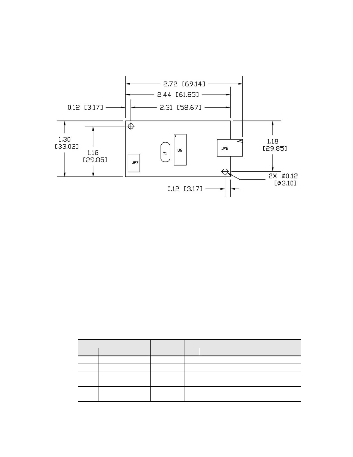
The controller measures 1.3 x 2.4 inches, or 1.3 x 2.7 inches total profile over the
connectors. Allow additional clearance for the mating connectors. The total height profile
is 0.40 inches from the thru hole pins on the trace side of the board to the top of the
highest component on the opposite side. The RX141 has a 4-pin sensor connector (JP6),
and a 5-pin USB cable connector (JP7).
3M Touch Systems, Inc. Proprietary Information
Page 10
10 3M™ MicroTouch™ Controller RX141 Reference Guide
Figure 1. RX141 Controller Overall Dimensions
Handling and ESD Protection
When mounting the sensor and controller, use normal precautions for handling
electrostatic sensitive devices. The RX141 has internal protection to ±20 kV for ESD air
discharges to the sensor (not to the controller directly) that may occur during normal
operation of the sensor. Refer to Appendix A for further specifications.
Establishing the Data Connection
The RX141 controller requires a 3M™ MicroTouch™ USB communication cable (P/N
7319420) PC 99 compatible or an equivalent interconnect. One end of this cable plugs
into the USB connector (JP7) on the RX141 controller. The other end, which has a TypeA connector, plugs into a USB port on your PC.
When creating a custom cable, use the Molex 51004-0500 mating connector. Table 1
describes the interconnections of the 3M™ MicroTouch™ USB cable.
Table 1. USB Cable for RX141 Controllers
PC Side (USB Type A) Wire Controller Side (5-Pin Molex)
Pin USB Assigned Color Pin Description
1 +5Vdc Red 1 +5Vdc Input Power
2 Data (DN) Gray 2 Data (DN) Differential Pair
3 Data (DP) Green 3 Data (DP) Differential Pair
4 0V Black 4 Power Return
5 Cable Shield Shell Charcoal
Gray
5 Outer Cable Shield around signal and
power lines. Chassis (earth) ground
3M Touch Systems, Inc. Proprietary Information
Page 11

3M™ MicroTouch™ Controller RX141 Reference Guide 11
Mounting the Controller
The controller is designed for internal mounting only. Choose a convenient spot away
from high-voltage, high power cables and electronics. Use 4-40 metal screws to mount
the controller using the two diagonal mounting holes in the board. The controller should
be mounted in line with the sensor cable exit point to minimize cable flexing. The
controller should be mounted internally behind or on the side of the display on stand offs
to allow room for the sensor cable connector.
Ensure that the tail and controller are aligned such that the tail remains straight (90°), not
pulled or twisted in an odd angle from the sensor. Good engineering design avoids
awkward electrical connections.
Recommended:
Wrap tail smoothly
Not recommended:
Do not twist the tail
Supplying Power to the Controller
The RX141 controller is powered by the USB 5-volt bus power. The typical current is 15
mA typical, 28 mA touching; ± 5% regulation, with a maximum ripple and noise of
50mV peak-to-peak.
CAUTION
To avoid possible damage to the controller, you must provide a path for electrostatic
discharge. The controller mounting hole near the sensor connector should be used to
connect to chassis safety ground and must be attached by the shortest possible route to
a good earth return (chassis) in all applications.
Sensor Cable Connector
The sensor cable should have a 4-pin single row locking female connector that plugs into
the controller. The controller is compatible with the “XYXY” latched connector pinout,
not the “XXYY” style, non-latched connector pinout. Here, X or Y refers to one or the
other sheet, and + or – refers or the other side of the sheet. The calibration process sorts
out left/right and up/down.
3M Touch Systems, Inc. Proprietary Information
Page 12

12 3M™ MicroTouch™ Controller RX141 Reference Guide
Connector pins 1 and 3 must be connected to one sheet and pins 2 and 4 must be
connected to the other sheet.
Y-
1.
2. X+
3. Y+
4. X-
Turning On Your System
Before you turn on your custom system, ensure that all cables are connected properly and
that the controller is properly mounted. Be sure to tighten all cable connector screws.
To start up your system
1. Turn on your monitor and computer.
2. Adjust the contrast and brightness to suit your personal preference and working
environment.
3. Adjust the horizontal and vertical position controls on the monitor to center the image
on the sensor.
Status Light (LED) Diagnostics
3M™ MicroTouch™ controllers are highly reliable units; however, there may be
occasions when the controller does not perform exactly as you expected. The RX141
controller provides diagnostic feedback with a light emitting diode (LED) on the
component side of the board that indicates the status of the sensor. During normal
operation, when you touch the sensor the LED becomes bright as long as the controller
detects a touch.
A flashing (or blinking) LED during power-up indicates the controller’s power-on
self-test failed. Refer to Table 2 for a description of each error code.
Table 2. LED Diagnostic Codes for RX141 Controllers
Flashes Self Test
Condition
1 Reserved. 0 Reserved
2 ROM Error 1 Firmware EPROM
3 Reserved. 2 Reserved
4 Block 1
checksum
Error
5 Hardware error 4 Power-up sensor
Self Test
Description What to do…
Bit
No recovery. Replace the
checksum verification
controller.
error
3 Operating parameters
invalid (using defaults).
Cycle power off and on. If
problem persists, recalibrate
Check connection to the sensor
connector voltages that are
out of range.
3M Touch Systems, Inc. Proprietary Information
Page 13

3M™ MicroTouch™ Controller RX141 Reference Guide 13
Flashes Self Test
Condition
Self Test
Bit
Description What to do…
6 Reserved. 5 Reserved
7 Reserved. 6 Reserved
What's Next?
Since this is a HID (human interface device) compatible controller, the controller will
operate independent of a 3M™ MicroTouch™ driver. You must obtain a HID calibration
utility from the 3M Touch Systems website.
Additional 3M Touch Systems documentation is available from the corporate website at
www.3Mtouch.com
.
3M Touch Systems, Inc. Proprietary Information
Page 14

Page 15

3M™ MicroTouch™ Controller RX141 Reference Guide 15
CHAPTER 2
RX141 Controller Communications
This chapter discusses the fundamentals of communicating with the RX141 controller.
The firmware commands, which are usually issued by a driver or utility program on the
host system, control the operation of the controller. This chapter lists the recommended
firmware commands and describes how to use each of these commands.
Overview of USB Firmware Communications
Developers may use this information when writing touch applications, developing custom
drivers or touch configurations, or testing their touch systems. Developers can issue
commands to initialize the controller, select operating modes, and execute diagnostic
functions.
Most touch systems users do not have to use firmware commands to use their touch
systems. For example, users can use 3M™ MicroTouch™ software or equivalent
software to calibrate the sensor or to determine the controller type and firmware version.
Note: This document assumes you are familiar with USB standards and modes of
communication with USB devices, as well as firmware commands and how to use them.
Executing some commands may alter the performance of your sensor and render it
inoperable. You should be aware of the results before executing any firmware
commands.
To optimize the performance of the RX141 controller and simplify the development of
custom drivers, 3M Touch Systems recommends you use the commands listed in this
chapter for current development.
3M Touch Systems, Inc. Proprietary Information
Page 16

16 3M™ MicroTouch™ Controller RX141 Reference Guide
Communication Basics
This section provides information on sending firmware commands to the controller and
interpreting the responses that the controller returns. The default operation of the RX141
controller is USB Rev 1.1.
The USB command set is implemented by using vendor requests and vendor reports, i.e.,
vendor specific transactions. The controller issues some reports without prompting the
computer. The computer can also send requests to the controller to change how it
operates or receives information about the controller. The controller issues a synchronous
report in response to some of these requests.
You need to know product ID (0100H) and the vendor ID (0596H) to write your own
driver. These values are required for identifying the controller.
The RX141 command set utilizes the HID protocol. The HID protocol allows the
controller to be used on most computers with operating systems that supports HID. The
only required software is a calibration tool used for aligning the sensor to the display.
This calibration tool is available from 3M Touch Systems.
Receiving Reports from the Controller
The controller sends a variety of reports to the computer. The first byte of each report is
the Report ID that defines the structure and content of the report. The controller sends
some reports as a direct response to a computer request (synchronous). The controller
will also send some reports as the result of an external event, such as a touch
(asynchronous).
HID and Packed Touch Reports
The controller sends to the computer reports in response to touches on the sensor. The
controller normally uses the HID-compatible report. In addition to the HID-compatible
report, there are two versions of packed report available. These versions return up to two
points of data per touch, as opposed to the one touch point in the HID-compatible report.
The first byte of each report contains the Report ID as shown in Table 3. You can use the
Set Asynchronous Report request to toggle between report types.
Table 3. Asynchronous Reports
Name Report ID Description
REPORT_ID_HID 1 HID-compatible coordinate data
REPORT_ID_PACKED 2 Packed coordinate data for custom
REPORT_ID_UTILITY 7 Packed coordinate data for utilities
driver
Only custom drivers and software can make use of the packed coordinate format. Refer to
the Set Asynchronous Report section for details on using packed coordinate data.
3M Touch Systems, Inc. Proprietary Information
Page 17

3M™ MicroTouch™ Controller RX141 Reference Guide 17
HID-Compatible Coordinate Data – Report 1
This is used to transfer the 10-bit coordinate data to the host. This report, when activated,
is sent to the host whenever new data is available/scheduled for transmission. It is an
asynchronous report that is activated by default at power up.
For HID class driver compatibility
• Throughput is limited to 125 points/sec.
• The coordinate system is upper-left origin, rather than the MicroTouch™ standard
lower-left origin.
Table 4. Coordinate Data Report
Offset Field Size Value Description
0 bReport
ID
1 BmStatus 1 B7, B6 B5, B
2 BXLsb 1 X7, X6 X5, X
3 BXMsb 1 XfXeXdX
4 BYLsb 1 Y7Y6Y5Y4 Y3Y2Y1Y0 Y (0-3FF)
5 BYMsb 1 YfYeYdY
6 Not used 2 0 Not used
1 0x01 REPORT_ID_HID
4 B3, B2 B1, B0
4 X3, X2 X1, X0
c XbXaX9X8
c YbYaY9Y8
0x01 if touching, 0x00 if not
X (0-3FF)
Packed Coordinate Data - Report 2 and Report 7
These are used to transfer the packed coordinate data to a custom driver or utility. These
reports, when activated, are sent to the host whenever new data is available for
transmission. The packed format contains two coordinate reports each with its own status
and Y and Y coordinate data. Because it is packed, the software must rearrange bits to
obtain the individual field values. The status contains a bit indicating if the sub report is
valid. The second sub report only may be invalid.
Table 5. Coordinate Data Report
Offset Field Size Value Description
0 bReport ID 1 0x02 or 0x07
1 bmPackData1 1 X3X2X1X0 B3B2B1B0 X1 bits 3210 and status1 bits
2 bmPackData2 1 XbXaX9X8 X7X6X5X4 X1 bits BA987654
3 bmPackData3 1 Y7Y6Y5Y4 Y3Y2Y1Y0 Y1 bits 76543210
4 bmPackData4 1 B3B2B1B0 YbYaY9Y8 Status2 bits BBBB and Y1 bits
5 bmPackData5 1 X7X6X5X4 X3X2X1X0 X2 bits 76543210
6 bmPackData6 1 Y3Y2Y1Y
0 XbXaX9X8
7 bmPackData7 1 YbYaY9Y8 Y7Y6Y5Y4 Y2 bits BA987654
REPORT_ID_PACKED
REPORT_ID_UTILITY
BBBB
BA98
Y2 bits 3210 and X2 bits
BA98
3M Touch Systems, Inc. Proprietary Information
Page 18

18 3M™ MicroTouch™ Controller RX141 Reference Guide
Table 6. Coordinate Data Report Touch Status Byte
Bit Status
0 0 = not touching, 1 = touching
1 0 = data invalid, 1 = data valid
2 Not used
3 Not used
USB Command Set
The USB command set is implemented by using HID Get Feature and Set Feature
commands. The various requests and reports are grouped together by report size under a
common feature ID.
The commands listed below are those that 3M Touch Systems currently use for
communications. 3M Touch Systems recommends that you use only these commands for
RX141 controller communications.
Sending Commands to the Controller
To send a command, the computer must construct a USB packet for sending to the
controller. The general packet format is described in Table 7. Any data appended
immediately after this data is referred to as the data stage of request.
If using Windows you may want to use the Set and Get Feature functions. The buffers are
the same except the first two fields. The bmRequest Type and bRequest fields are
omitted, thus making wValue the first field. For your convenience, each command is
labeled as either a “Set Feature” or “Get Feature” command.
Table 7. General Request Format
Offset Field Size Value Description
0 bmRequestType 1 d0100001 Characteristics of request (dir,type,receipt)
D7: Data transfer direction
0 = Host to device
1 = Device to host
D6…5 Type
0 = Standard
1 = Class (all commands are standard)
2 = Vendor
3 = Reserved
D4…0 Recipient
0 = Device
1 = Interface (all commands are interface)
2 = Endpoint
3 = Other
4….31 = Reserved
1 bRequest 1 0xXX Specific request (our command number)
3M Touch Systems, Inc. Proprietary Information
Page 19

3M™ MicroTouch™ Controller RX141 Reference Guide 19
Offset Field Size Value Description
2 wValue 2 0x03XX Used to specify command parameters.
03 = Feature
XX = Feature Report ID
4 wIndex 2 0 Must be 0 (zero)
6 wLength 2 0xXXXX Number of bytes to transfer, multiple of 8. Same
as Data Stage Bytes in Table 8.
HID Class Requests
The following table summarizes the available HID class requests.
Table 8. HID Class Requests Summary
HID Report Command
Name
bmRequest
Type
bRequest Feature
Report ID
Report
Subtype
Data
Stage
Bytes
Set Feature SetAsyncReport 0x21 0x09 0x03 0x05 8
Set Feature Calibrate 0x21 0x09 0x03 0x04 8
Get Feature GetStatus 0xA1 0x01 0x06 --- 8
Set Feature Reset 0x21 0x09 0x03 0x07 8
Set Feature Restore Defaults 0x21 0x09 0x03 0x08 8
Set Feature Set Controller
0x21 0x09 0x05 0x01 8
Number
Get Feature Get Controller
0xA1 0x01 0x05 --- 72
Number
Some possible reasons for a command failure include:
• The command was not formatted correctly.
• The system parameters were not set up to allow command execution.
• The controller does not support the command.
Controller Initialization
To initialize the RX141 controller, 3M Touch Systems recommends that the host system
issue a Reset command whenever the host system is powered on and is attempting to
establish communication with the controller.
Set Feature – Set Asynchronous Report
This starts or stops the sending of various asynchronous reports via the interrupt pipe.
Once a report is turned on, that report is sent whenever data is available. The firmware
defaults to the HID-compatible report after power-up or reset. Only one report may be
activated at a time.
3M Touch Systems, Inc. Proprietary Information
Page 20

20 3M™ MicroTouch™ Controller RX141 Reference Guide
Note: The Touch_Reports_Utility command causes the controller to send Report 7 from
the endpoint 0 exclusively. This action is essential in getting a calibration utility to
function. The endpoint 1 does not send any reports at this time. The
Touch_Reports_Restore command causes the controller to send the previously active
asynchronous report (REPORT_ID_HID or REPORT_ID_PACKED) from endpoint 1.
Table 9. Set Asynchronous Report
Offset Field Size Value Description
0 bmRequestType 1 0x21 Host to device
1 bRequest 1 0x09 Set Report
2 wValue 2 0x0303 03 = Feature
03 = Feature Report ID
4 wIndex 2 0 Always 0
6 wLength 2 8 Always 8
Table 10. Data Stage
Offset Field Size Value Description
0 bReport ID 1 0x03 Feature Report ID
1 bmReport Subtype 1 0x05 Indicates a SetAsynchReport
2 Not used 2 0 Not used
4 bReport 0x00 0 Touch_Reports_Off
1 Touch_Reports_On
2 Touch_Reports_HID
3 Touch Reports_Packed
6 Touch_Reports_Utility
7 Touch_Reports_Restore
5 Not used 3 Not used
Response
The device stalls endpoint 0 if it cannot process this request.
Set Feature – Calibration
This is a request to perform a 3-point calibration. The calibration can be performed at
points inset from the lower left, upper left and upper right corners. The 3-point
calibration defines the active area of the sensor by mapping two targets displayed on the
video image to absolute X and Y coordinates on the sensor.
3M Touch Systems, Inc. Proprietary Information
Page 21

3M™ MicroTouch™ Controller RX141 Reference Guide 21
Table 11. Set Feature - Calibration
Offset Field Size Value Description
0 bmRequestType 1 0x21 Host to device
1 bRequest 1 0x09 Set Report
2 wValue 2 0x0303 03 = Feature
03 = Feature Report ID
4 wIndex 2 0 Always 0
6 wLength 2 8 Always 8
Table 12. Data Stage
Offset Field Size Value Description
0 bReport ID 1 0x21 Host to device
1 bmReport
1 0x04 Set Report
Subtype
2 bCalType 1 0xXX 0x03 = 3-point calibration (C3)
3 Not used 5 0 Not used
Response
The device stalls endpoint 0 if the command cannot be processed successfully. The
request cannot be processed if an invalid calibration type is given in the wValue field.
During the calibration process, the calibration software polls the Get Status command to
monitor the progress of the calibration.
The calibration will fail if the three calibration points do not fall within certain bounds
established by the firmware. These bounds require that the 3 calibration points be in
correct quadrants of the sensor.
Calibration software can abort the calibration process with a Reset Request.
During the calibration process, the controller automatically determines display orientation
and connector pinouts. This information is saved in the controller non-volatile memory.
Table 13. Calibration Response
Command
Description
Status Byte
0 Calibration Failed
1 Controller is waiting for a touch in the lower left corner.
Calibration software paints a target in the lower left corner.
2 Controller is waiting for a touch in the upper right corner.
Calibration software paints a target in the upper right corner.
3 Calibration completed successfully.
6 Controller is waiting for a touch in the upper left corner.
Calibration software paints a target in the upper left corner.
This command corrects for display orientation and pinout variations. This information
3M Touch Systems, Inc. Proprietary Information
Page 22

22 3M™ MicroTouch™ Controller RX141 Reference Guide
will be maintained by the controller. The Calibrate 3 Point command initiates an
interactive calibration procedure which defines the active area of the sensor by mapping
locations to an absolute X,Y coordinate system. Touch points generated subsequent to a
successful calibration operation are calculated based upon these calibration points.
Calibrate 3 Point utilizes inset calibration points located 12½ percent inboard from the
sensor corners (at touch X,Y locations 128,128, 895,895 and 128,895) for accuracy and
ease of operation.
Guidelines for the Controller Command
Here are several guidelines for using the Calibration command:
• The controller uses the data immediately before liftoff to register a calibration touch.
Therefore, you can touch the coordinate target, hold for a few seconds, and then lift
off. Instructing users to touch this way results in a more accurate calibration.
• The controller stores the data in non-volatile memory (NOVRAM). Therefore, you
do not have to calibrate the sensor each time you power on the system. You should,
however, recalibrate the sensor any time the video display changes size or resolution.
• You can restart calibration at any time during this sequence by issuing a Reset
command and reissuing a Controller command.
Determining Target Areas
The default calibration targets (points) are located 12.5% (1/8) inward from the corners of
the video image. For example, suppose the display resolution of your Windows-based
monitor is 1024 x 768. The Calibration command calculates the amount to move inward
as follows:
• Amount to move inward in the X direction: 1024 x 1/8 = 128
• Amount to move inward in the Y direction: 768 x 1/8 = 96
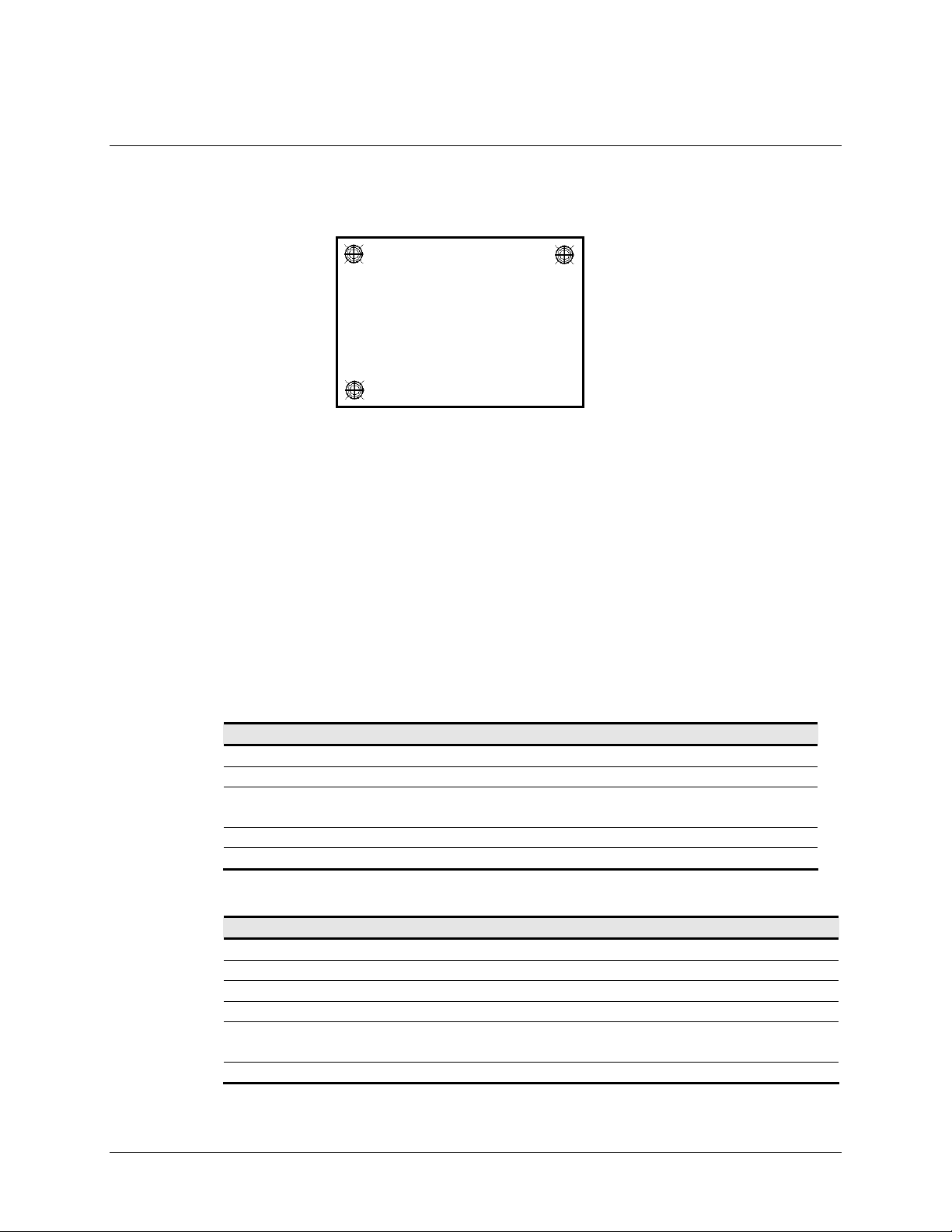
The Calibration command then positions the first calibration target inward from the lower
left corner (0,767) and the second calibration target inward from the upper right corner
(1023,0). The following illustration shows how the calibration targets are calculated for a
Windows-based system. Your operating system may be different.
3M Touch Systems, Inc. Proprietary Information
Page 23
3M™ MicroTouch™ Controller RX141 Reference Guide 23
(
(
Figure 2. Calibration Target Locations
0, 0) [0, 1024]*
Upper Left Calibration Target
X = 1024 x 1/8 = 128
Y = 768 x 1/8) = 96
Lower Left Calibration Target
X = 0 + (1024 x 1/8) = 0 + 128 = 128
Y = 767 - (768 x 1/8) = 767 - 96 = 671
*The coordinates are in video terms, with the origin (0, 0) in the upper left corner of the sensor. Examples from the
controller’s perspective, however, place the origin at the lower left corner of the sensor (numbers in brackets). The
controller outputs 0 to 64K on both axes independent of display screen resolution.
(128, 96)
(0, 767) [0, 0]* [1024, 0]*
Get Feature – Get Status
This is a request to send information that indicates the status of the controller. Among the
uses for this request are determining whether there were any power on check errors
determining whether the last request was completed successfully.
The response to the reset request is sent before the request completes. Polling (via the
status request) is then used to check the completion of those requests.
(128, 671)
(1023, 0) [1024, 1024]*
(895, 96)
Upper Right Calibration Target
X = 1023 – (1024 x 1/8) = 1023 – 128 = 895
Y = 0 +
768 x 1/8) = 0 + 96 = 96
Table 14. Controller Status
Offset Field Size Value Description
0 bmRequestType 1 0xA1 Host to device
1 bRequest 1 0x01 Get Report
2 wValue 2 0x0306 03 = Feature
06 = Feature Report ID
4 wIndex 2 0 Always 0
6 wLength 2 8 Always 8
Table 15. Data Stage (controller response)
Offset Field Size Value Description
0 bReport ID 1 0x06 Feature Report ID
1 bPOCStatus 1 0xXX Power On Check Status
2 bCmdStatus 1 0xXX Status of last command
3 bTouchStatus 1 0xXX Finger Up/Down
4 bAsynchReports 1 0xXX 0x00 = asynchronous output off
0x01 = normal output
5 Not used 3 0 Not used
POC Status – The status of the Power-on Checks. Various controller systems are checked
3M Touch Systems, Inc. Proprietary Information
Page 24

24 3M™ MicroTouch™ Controller RX141 Reference Guide
at power-up. If any failures in these systems are detected, a POC flag is set. The POC
status field reports the state of these flags. The POC status information is also flashed on
the controller’s LED.
Table 16. Power On Status
Bit
Number
LED
Flashes
Description
0 1 Not used
1 2 Program code checksum error
2 3 Not used
3 4 Block 1 parameters invalid (using defaults)
4 5 Power-up connector voltages are out of range
5 6 Not used
6 7 Not used
7 8 Controller linearization data invalid
Cmd Status – The status for the last command request. This field is used to determine
whether the last request was processed successfully. It is also used to track the progress
of a multi-stage request, such as calibration. The Status Request does not affect the
contents of this field, i.e., successful/unsuccessful processing of a previous status request
does not cause the command status field to be updated.
Table 17. Command Status Field Entries
Response Description
0 Failure in command processing
1 Command being processed
2 Stage 1 processing complete (for multi-stage commands).
3 Command complete
4 Soft reset occurred
5 Hard reset occurred
6 Stage 2 processing complete (for multi-stage commands)
7 Not used
Touch Status – Status information for the most recent coordinate. Information includes
whether the sensor is currently being touched.
Table 18. Power On Check Bit Fields
Bit
Description
Number
0 1 if the sensor is being touched
1 Always 0
3M Touch Systems, Inc. Proprietary Information
Page 25

3M™ MicroTouch™ Controller RX141 Reference Guide 25
Set Feature - Reset
This is a request to perform a controller reset.
Table 19. Reset Request
Offset Field Size Value Description
0 bmRequestType 1 0x21 Host to device
1 bRequest 1 0x09 Set Report
2 wValue 2 0x0303 03 = Feature
03 = Feature Report ID
4 wIndex 2 0 Always 0
6 wLength 2 8 Always 8
Table 20. Data Stage
Offset Field Size Value Description
0 bReport ID 1 0x03 Host to device
1 bmReport Subtype 1 0x07 Indicates a reset request
2 bResetType 1 0xXX 0x01=Soft reset
3 Not used 5 0 Not used
Response
The device stalls endpoint 0 if the request cannot be processed successfully. The request
cannot be processed if the reset type specified by the bResetType field is not valid.
Set Feature - Restore Defaults
This is a request to restore the default values in the controller to the factory presets. You
must recalibrate after this command since this request will also default the calibration and
display orientation.
Table 21. Restore Defaults Request
Offset Field Size Value Description
0 bmRequestType 1 0x21 Host to device
1 bRequest 1 0x09 Set Report
2 wValue 2 0x0303 03 = Feature
4 wIndex 2 0 Always 0
6 wLength 2 8 Always 8
03 = Feature Report ID
3M Touch Systems, Inc. Proprietary Information
Page 26

26 3M™ MicroTouch™ Controller RX141 Reference Guide
Table 22. Data Stage
Offset Field Size Value Description
0 bReport ID 1 0x03 Feature Report ID
1 bmReportSubtype 1 0x08 Indicates a restore defaults request
2 Not used 6 0 Not used
Response
The device stalls endpoint 0 if it cannot process this request.
Set Feature - Set Controller Number
This command is used to get a controller number for application use. The controller does
not use this value. This process is useful for identifying individual controllers in a
multiple controller system.
Table 23. Set Controller Number Request
Offset Field Size Value Description
0 bmRequestType 1 0x21 Characteristics
1 bRequest 1 0x09 Command number
2 wValue 2 0x0305 Parameter number
4 wIndex 2 0x00 Not used
6 wLength 2 0x48 Length of Parameter Data report
Table 24. Data Stage 1 (header data)
Offset Field Size Value Description
0 bReportID 1 0x05 Feature Report ID
1 bReport
1 0x01 Indicates a set param report
Subtype
2 bArea 1 0 Memory Area (always 0=Ctrl EEPROM)
3 Not used 1 0 Not used
4 bSubArea 1 0x05 Block number
5 bIndex 1 0x00 Index into block
6 bDataLength 1 0x04 Number of valid data bytes for this xfer
(always padded to 64)
7 Not used 1 0x00 Not used
Table 25. Data Stage 2 through 9 (8 * 8 data bytes)
Offset Field Size Value Description
0-7 wData 1 0xXX 4 bytes of data (trailing pad bytes are ignored )
Data Stage
The controller ID is in the first 4 bytes of data stage, the remaining bytes are padding.
3M Touch Systems, Inc. Proprietary Information
Page 27

3M™ MicroTouch™ Controller RX141 Reference Guide 27
Response
If the command cannot be processed, the device stalls endpoint 0. The command cannot
be processed if the memory area is not valid. It cannot be processed if the request is
attempting to access data that is outside the specified memory area. This may happen if
the index is too large or too much data has been requested.
The host can send a status request, as long as the endpoint is not stalled, to determine if
this request was executed properly.
Get Feature – Get Controller Number
This command is used to get a controller number for application use. The controller does
not use this value. This process is useful for identifying individual controllers in a
multiple controller system.
Due to HID functionality, retrieving data from the controller involves two steps.
1. Requesting the controller number parameter
2. Retrieving the controller number value
Table 26. Get Controller Number Parameter Request
Offset Field Size Value Description
0 bmRequestType 1 0x21 Device to host
1 bRequest 1 0x09 Set Report
2 wValue 2 0x0303 03 = Feature
03 = Feature Report ID
4 wIndex 2 0 Always 0
6 wLength 2 0 Always 8
Table 27. Data Stage
Offset Field Size Value Description
0 bReport ID 1 0x03 Feature Report ID
1 bmReport
1 0x02 Indicates a set param index
Subtype
2 bArea 1 0 Memory Area (always 0=Ctrl
EEPROM )
3 Not used 1 0 Not used
4 bSubArea 1 0x05 Block number
5 bIndex 1 0x00 Index into block.
6 bDataLength 1 0x04 Number of valid data bytes for
xfer (always padded to 64)
7 Not used 1 0 Not used
3M Touch Systems, Inc. Proprietary Information
Page 28

28 3M™ MicroTouch™ Controller RX141 Reference Guide
Table 28. Get Controller Number Report
Offset Field Size Value Description
0 bmRequestType 1 0xA1 Device to host
1 bRequest 1 0x01 Get Report
2 wValue 2 0x0305 03 = Feature
05 = Feature Report ID
4 wIndex 2 0 Always 0
6 wLength 2 0x48 Always 72 (allows for 64 data
bytes + 8 byte header)
Table 29. Data Stage 1 (controller response header)
Offset Field Size Value Description
0 Report ID 1 0x05 Feature Report ID
1 Not used 1 0 Not used
2 bArea 1 0 Memory Area (always 0=Ctrl
EEPROM )
3 Not used 1 0 Not used
4 bSubArea 1 0x05 Block number
5 bIndex 1 0x00 Index into block. Use 0 for
controller number
6 bDataLength 1 0x04 Number of valid data bytes for
xfer (always padded to 64)
7 Not used 1 0 Not used
Table 30. Data Stage 2 through 9 (controller response data 8 * 8 data bytes)
Offset Field Size Value Description
0-7 wData 1 0xXX 4 bytes of data (trailing pad bytes
are ignored )
Data Stage
The controller ID is in the first 4 bytes of data stage, the remaining bytes are padding.
Response
If the command cannot be processed, the device stalls endpoint 0. The command cannot
be processed if the memory area is not valid. It cannot be processed if the request is
attempting to access data that is outside the specified memory area. This may happen if
the index is too large or too much data has been requested.
The host can send a status request, as long as the endpoint is not stalled, to determine if
this request was executed properly.
3M Touch Systems, Inc. Proprietary Information
Page 29

3M™ MicroTouch™ Controller RX141 Reference Guide 29
APPENDIX A
RX141 Controller Specifications
This section provides controller specifications such as power and environmental
requirements. The RX141 controller is a compact, small outline USB controller. This
controller should be internally mounted in your monitor.
The following figure shows the overall dimensions of the RX141 controller and the
locations of the mounting holes and connectors.
Figure 3. RX141 Controller Dimensions
3M Touch Systems, Inc. Proprietary Information
Page 30

30 3M™ MicroTouch™ Controller RX141 Reference Guide
Technical Specifications
Physical Dimensions
Uncased 2.75 in. x 1.3 in. x 0.45 in. (69.9 mm x 33.0 mm x 11.4 mm)
Board Level Functions
Power 5 VDC / 12 VDC (15 mA typical, 28 mA touching); ± 5% regulation
50 mV maximum ripple and noise
Regulatory Requirements
CE Compliance Compliant
EMC Emissions – EN 55022:1998 Compliant
EMC Immunity – EN 55024:1998 Compliant
ESD Susceptibility – IEC 61000-4-2 Compliant
EMI Immunity – IEC 61000-4-3 Compliant
Burst Immunity – IEC 1000-4-4 Compliant
FCC Class B / CISPR22 Class B Compliant
VCCI Class B ITE Emissions (Japan) Compliant
AS/NZS 3548:1995/CISPR 22 Class B ITE Emissions (Aus.) Compliant
UL/cUL Compliant
Ambient Operating and Storage Environmental Conditions
Note: All humidity is non-condensing
Operating Temperature Range 0°C to +65°C
Operating Humidity Range (0 to 95% RH up to +36°C; above 36°C refer to Figure 4
below)
Storage Temperature Range -20°C to +75°C
Storage Humidity Range (0 to 80% RH up to +36°C; above 36°C refer to Figure 4
below)
Performance and Reliability
Minimum Touch Duration 14 ±1 ms
Touch Resolution 1024 x 1024
(Maximum number of addressable coordinates generated by the controller)
ESD Susceptibility
1
±8KV Contact Discharge– Class 2 per section 9 of IEC 61000-4-2 Compliant
1
ESD discharges to a sensor connected to the controller
3M Touch Systems, Inc. Proprietary Information
Page 31

3M™ MicroTouch™ Controller RX141 Reference Guide 31
1 false touch allowed
±20KV Air Discharge – Class 1 per section 9 of IEC 61000-4-2 Compliant
Normal Operation – No false touches
MTBF (by MIL Std. 217F Calculation) >400,000 Hours
3M Touch Systems Parameters
Accuracy vs. Dynamic Temperature Change Maintains 1% Accuracy
(tested at 0° C to 65° C with a 0.5° C/minute temperature ramp)
Communications Protocol USB Rev 1.1
Figure 4. Storage and Operating Temperature and Humidity Conditions
3M Touch Systems, Inc. Proprietary Information
 Loading...