

3M AP510 Installation Manual
Installation and Operating Instructions For
AP510 Full Flow Drinking Water System
Installer: Please leave manual with homeowner.
Homeowner: Please retain for operation and
future maintenance instructions.

SAFETY INFORMATION
WARNING
CAUTION
Read, understand, and follow all safety information contained in these instructions prior to
installation and use of the AP510 Full Flow Drinking Water System. Retain these instructions
for future reference.
Intended use:
The AP510 Full Flow Drinking Water System is intended for use in fi ltering potable water in homes and has not
been evaluated for other uses. The system is typically installed under a sink using the existing faucet, and
must be installed as specifi ed in the installation instructions.
EXPLANATION OF SIGNAL WORD CONSEQUENCES
W
To reduce the risk associated with choking:
• Do not allow children under 3 years of age to have access to small parts during the installation of this product.
To reduce the risk associated with ingestion of contaminants:
• Do not use with water that is microbiologically unsafe or of unknown quality without adequate disinfection before or
after the system.
To reduce the risk associated with a hazardous voltage due to an installer drilling through existing electric wiring
or water pipes in the area of installation:
• Do not install near electric wiring or piping which may be in the path of a drilling tool when selecting the position
to mount the fi lter bracket.
Indicates a potentially hazardous situation, which, if not avoided, could result in
death or serious injury and/or property damage.
Indicates a potentially hazardous situation, which, if not avoided, may result in
property damage.
WARNING
CAUTION
To reduce the risk associated with property damage due to water leakage:
• Read and follow Use Instructions before installation and use of this system.
• Installation and Use MUST comply with all state and local plumbing codes.
• Protect from freezing, remove fi lter cartridge when temperatures are expected to drop below 40°F (4.4°C).
• Do not install systems in areas where ambient temperatures may go above 110° F (43.3° C).
• Do not install on hot water supply lines. The maximum operating water temperature of this fi lter system is 100°F
(37.8°C).
• Do not install if water pressure exceeds 125 psi (862 kPa). If your water pressure exceeds 80 psi (552 kPa), you
must install a pressure limiting valve. Contact a plumbing professional if you are uncertain how to check your
water pressure.
• Do not install where water hammer conditions may occur. If water hammer conditions exist you must install a
water hammer arrester. Contact a plumbing professional if you are uncertain how to check for this condition.
• Where a backfl ow prevention device is installed on a water system, a device for controlling pressure due to
thermal expansion must be installed.
• Do not use a torch or other high temperature sources near fi lter system, cartridges, plastic fi ttings or plastic
plumbing.
• On plastic fi ttings, never use pipe sealant or pipe dope. Use PTFE thread tape only, pipe dope properties may
deteriorate plastic.
• Take care when using pliers or pipe wrenches to tighten plastic fi ttings, as damage may occur if overtightening
occurs.
• Do not install in direct sunlight or outdoors.
• Mount fi lter in such a position as to prevent it from being struck by other items used in the area of installation.
• Ensure that the location and fasteners will support the weight of the system.
• Ensure all tubing and fi ttings are secure and free of leaks.
• The disposable fi lter cartridge MUST be replaced ever 6 months, at the rated capacity or if a noticeable reduction in fl ow rate occurs.
IMPORTANT NOTES
• Failure to follow instructions will void warranty.
• Allow a minimum of 3” (7.6 cm) clear space under fi lter to facilitate cartridge change.
• Install with the inlet and outlet ports as labeled. Make sure not to reverse connections.
• Do not crimp copper tubing.
GETTING STARTED
Your new Aqua-Pure® AP510 Full Flow Drinking Water System will reduce chlorine tastes and odors, particulate and
scale from your drinking water. The filter installs under the sink on the cold water line and uses the existing faucet. The
AP510 features its own automatic shut-off, thereby eliminating the need for any external valves. The installation procedure covered in this manual requires the removal of a section of the cold water tube. Soft copper tubing and compression fittings should be purchased locally to complete the installation.
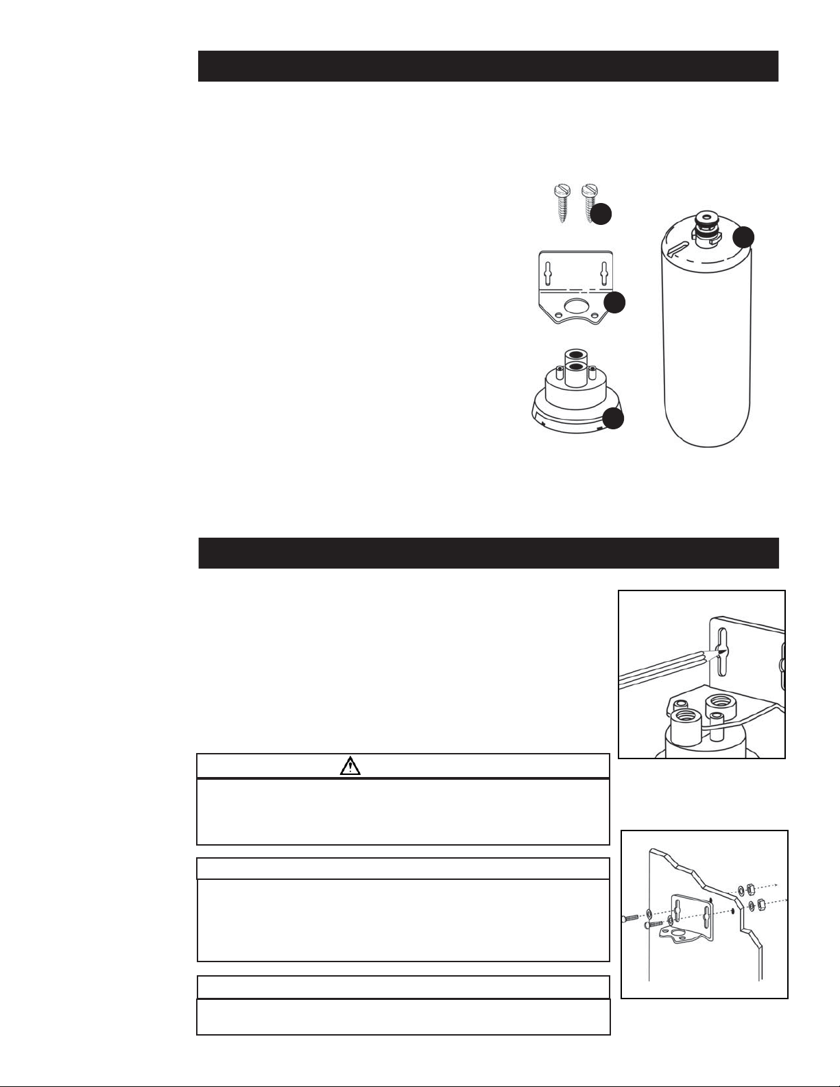
Parts and Materials Included:
1. Two Self-tapping Screws
2. Mounting Bracket
3. Head Assembly
4. Cartridge Model AP517
Tools and Parts Required (not included):
• Choice of:
Two #10 Machine Screws (length to suit), Two Washers and
Two #10 Machine Screw Nuts
OR Two #10 Sheet Metal Screws and Two Washers
OR Two Wood Screws
• Two 3/8” MNPT x 3/8” or 1/2” Compression
Fittings Depending on Existing Plumbing
• PTFE Tape
• Adjustable Wrench
• Drill (Cordless Recommended)
• Phillips Head Screwdriver
• Razor Knife Or Tube Cutter
• 3/8” soft copper or plastic tubing, 5’ length
Empty contents of package and identify all parts as shown in
diagram. Read all instructions carefully before attempting to start
installation. Before starting, close shut-off valve on kitchen
cold water line.
Note: If the filter is not connected to the head assem-
bly upon opening this carton, please refer to the
“Filter Cartridge Replacement Instructions” Section,
Step 3.
1
4
2
3
IMPORTANT INSTALLATION INSTRUCTIONS
1. Position the filter by holding it against the right hand side of the cabinet wall
underneath the sink. Allow at least 3” (7.6 cm) beneath the filter to install cartridge. Determine a desirable location for the filter installation and inlet connection. Attach the mounting bracket to appropriate mounting bosses on filter head
with the self-tapping screws supplied. (Figure 1)
2. For installation using machine screws and nuts, remove drawer from adjacent
cabinet and drill two 7/32” diameter holes through cabinet wall. Fasten filter
bracket to wall with screws, nuts and washers. Use washers on both sides of the
wall. Mounting to the cabinet side wall gives the filter good, rigid support. (Figure
2) For installation using sheet metal screws, simply prick punch at marked location (Step 1), position bracket in place, and install screws with screwdriver.
WARNING
To reduce the risk associated with a hazardous voltage due to an installer drilling through existing electric wiring or water pipes in the area of installation:
• Do not install near electric wiring or piping which may be in the path of a
drilling tool when selecting the position to mount the fi lter bracket.
CAUTION
To reduce the risk associated with property damage due to water leakage:
• Do not install on hot water supply lines. The maximum operating water
temperature of this fi lter system is 100°F (37.8°C).
• Do not use a torch or other high temperature sources near fi lter system,
cartridges, plastic fi ttings or plastic plumbing.
Figure 1
IMPORTANT NOTES
• Allow a minimum of 3” (7.6 cm) clear space under fi lter to facilitate
cartridge change.
Figure 2
IMPORTANT INSTALLATION INSTRUCTIONS (Continued)
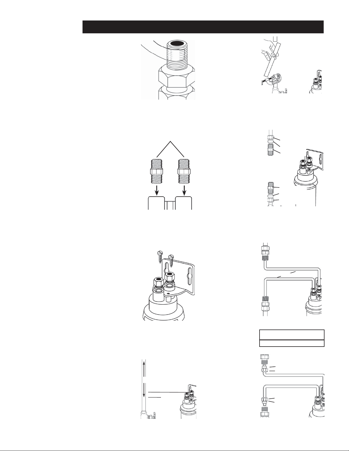
3. Wrap a 3” (7.6 cm)
long piece of PTFE tape
to the right (clockwise)
around the 3/8” MNTP
threads of the fittings.
Wrap tightly so that
it conforms to the
threads of the fitting
and overlaps about
1/2”. (Figure 3) Do
not wrap 3/8” or 1/2”
compression threads
with tape.
4. Screw one fitting
into the filter outlet
and the other fitting
into the filter inlet
(both are labeled on
filter head assembly.)
Tighten both fittings
with a wrench. Do
not overtighten.
Overtightening may
result in a cartridge
crack which may
lead to fluid leaking
(Figure 4)
5. Remove the two
screws at top of head
assembly. Position
either inlet fitting or
outlet fitting through
large hole in bracket
and replace these two
screws. Filter head
is now mounted and
ready for plumbing.
(Figure 5)
6. Measure down from
filter inlet fitting about
1” (3 cm) and mark
existing cold water
tubing. From this
mark, measure up
8” (20 cm) and mark
tubing. This is the
section of tubing to
be removed. If necessary, because of tight
situations, additional
tubing may be cut
away. (Figure 6)
PTFE Tape
Compression
Fittings
Compression Fittings
8”
1”
Figure 3
Figure 4
Figure 5
Cold Water Line
Figure 6
7. Turn off cold water
supply valve and open
cold water tap to
relieve system pressure. Cut cold water
tubing using a tube
cutter or razor knife.
Do not use a hacksaw,
etc. Place a pan under
it to catch any water
present. (Figure 7)
8. Two compression
fittings are required
for tube ends. Check
tube size. Use 3/8”
x 3/8”, 1/2” x 3/8”,
or 5/8” x 3/8” compression fittings as
required. Slip nut
and ferrule on water
tubing as shown
and fasten fittings in
place. (Figure 8)
9. Cut two lengths of
3/8” soft copper
tubing and bend to
shape as shown.
Bend tubing to form
gentle curves rather
than sharp bends.
(Figure 9)
10. Connect both pieces
of tubing to filter and
water tube as shown
with compression
fittings. Do not over-
tighten nuts.
(Figure 10)
11. Open the cold water
faucet to expel
trapped air. Open
the supply valve to
allow water to enter
the filter. If any leaks
occur, close the supply valve and open
the faucet to relieve
the pressure, then
gently tighten the
fitting that is leaking. Flush at least 2
gallons through filter
before use (approximately 1 minute of
flushing). Water may
run cloudy due to air
but will clear quickly.
Figure 7
Nut
Ferrule
Compression Fitting
Compression Fitting
Ferrule
Nut
Figure 8
To existing faucet
(cold water side only)
Tubing
Head
Figure 9
IMPORTANT NOTE
Do not crimp copper tubing.
Ferrule
Nut
Nut
Ferrule
Figure 10
 Loading...