

3M AP430SS Installation Manual
Installation and Operating Instructions For
Scale Inhibition System
Model AP430SS
Installer: Please leave manual with homeowner.
Homeowner: Please retain for operation and
future maintenance instructions.
SAFETY INFORMATION
WARNING
Read, understand, and follow all safety information contained in these instructions prior to
installation and use of the Scale Inhibition System Model AP430SS. Retain these instructions
for future reference.
Intended use:
The Scale Inhibition System Model AP430SS is intended for use in treatment of potable water and has not been
evaluated for other uses. The product is installed at the point of entry (main distribution pipe) and must be
installed as specifi ed in the installation instruction by a qualifi ed professional.
EXPLANATION OF SIGNAL WORD CONSEQUENCES
W
NOTICE
To reduce the risk associated with choking:
• Do not allow children under 3 years of age to have access to small parts during the installation of this product.
To reduce the risk associated with ingestion of contaminants:
• Do not use with water that is microbiologically unsafe or of unknown quality without adequate disinfection
before or after the system.
To reduce the risk of physical injury:
• Depressurize system as shown in manual prior to cartridge removal.
Indicates a potentially hazardous situation, which, if not avoided, could result in
death or serious injury and/or property damage.
Indicates a potentially hazardous situation, which, if not avoided, may result in
property damage.
WARNING
NOTICE
To reduce the risk associated with property damage due to water leakage or fl ooding:
• Read and follow Use Instructions before installation and use of this system.
• Installation and use MUST comply with all state and local plumbing codes.
• Protect from freezing, remove fi lter cartridge when temperatures are expected to drop below 40°F (4.4°C).
• Do not install systems in areas where ambient temperatures may go above 110° F (43.3° C).
• Do not install on hot water supply lines. The maximum operating water temperature of this system is 100°F
(37.8°C).
• Do not install if water pressure exceeds 125 psi (862 kPa). If your water pressure exceeds 80 psi (552 kPa),
you must install a pressure limiting valve. Contact a plumbing professional if you are uncertain how to check
your water pressure.
• Do not install where water hammer conditions may occur. If water hammer conditions exist you must
install a water hammer arrester. Contact a plumbing professional if you are uncertain how to check for this
condition.
• Do not use a torch or other high temperature sources near system, cartridges, plastic fi ttings or plastic
plumbing.
• On plastic fi ttings, never use pipe sealant or pipe dope. Use PTFE thread tape only, pipe dope properties may
deteriorate plastic.
• Take care when using pliers or pipe wrenches to tighten plastic fi ttings, as damage may occur if over
tightening occurs.
• Do not install in direct sunlight or outdoors.
• Mount system in such a position as to prevent it from being struck by other items used in the area of
installation.
• Ensure that the location and fasteners will support the weight of the system when installed and full of water.
• Ensure all tubing and fi ttings are secure and free of leaks.
• SHUT OFF FUEL OR ELECTRIC POWER SUPPLY TO WATER HEATER after water is shut off.

NOTICE
• Where a backfl ow prevention device is installed on a water system, a device for controlling pressure due to thermal
expansion must be installed. Contact a plumbing professional if you are uncertain how to select/install/maintain a
thermal expansion device.
• Where a booster pump is installed on a water system, you must maintain and inspect the attached pressure switch
regularly in accordance with the booster pump manufacturer’s instructions. Contact a plumbing professional if you
are uncertain how to maintain your booster pump system.
• Where a booster pump is installed on a water system, you must install an appropriate pressure relief valve. Pressure
relief valve must be maintained and inspected every 6 months. Contact a plumbing professional if you are uncertain
how select/install/maintain a pressure relief valve.
• Where a booster pump is installed on a water system, you must install an appropriate pressure regulating valve and
regulate water pressure to <80psi. Contact a plumbing professional if you are uncertain how select/install/maintain a
pressure regulating valve.
To reduce the risk of water leakage of fl ooding, and to ensure optimal fi lter performance:
• Change the disposable fi lter cartridge every 6 months or sooner if you observe a noticeable reduction in water fl ow
rate.
• Failure to replace the disposable fi lter cartridge at recommended intervals may lead to reduced fi lter performance and
cracks in the fi lter housing, causing water leakage or fl ooding.
• For questions or concerns, please contact Customer Service at 1-800-222-7880.
IMPORTANT NOTES
• Failure to follow instructions will void warranty.
• Allow a minimum of 2” (5.1 cm) clear space under fi lter to facilitate cartridge change.
• Install with the inlet and outlet ports as labeled. Make sure not to reverse connections.
GETTING STARTED
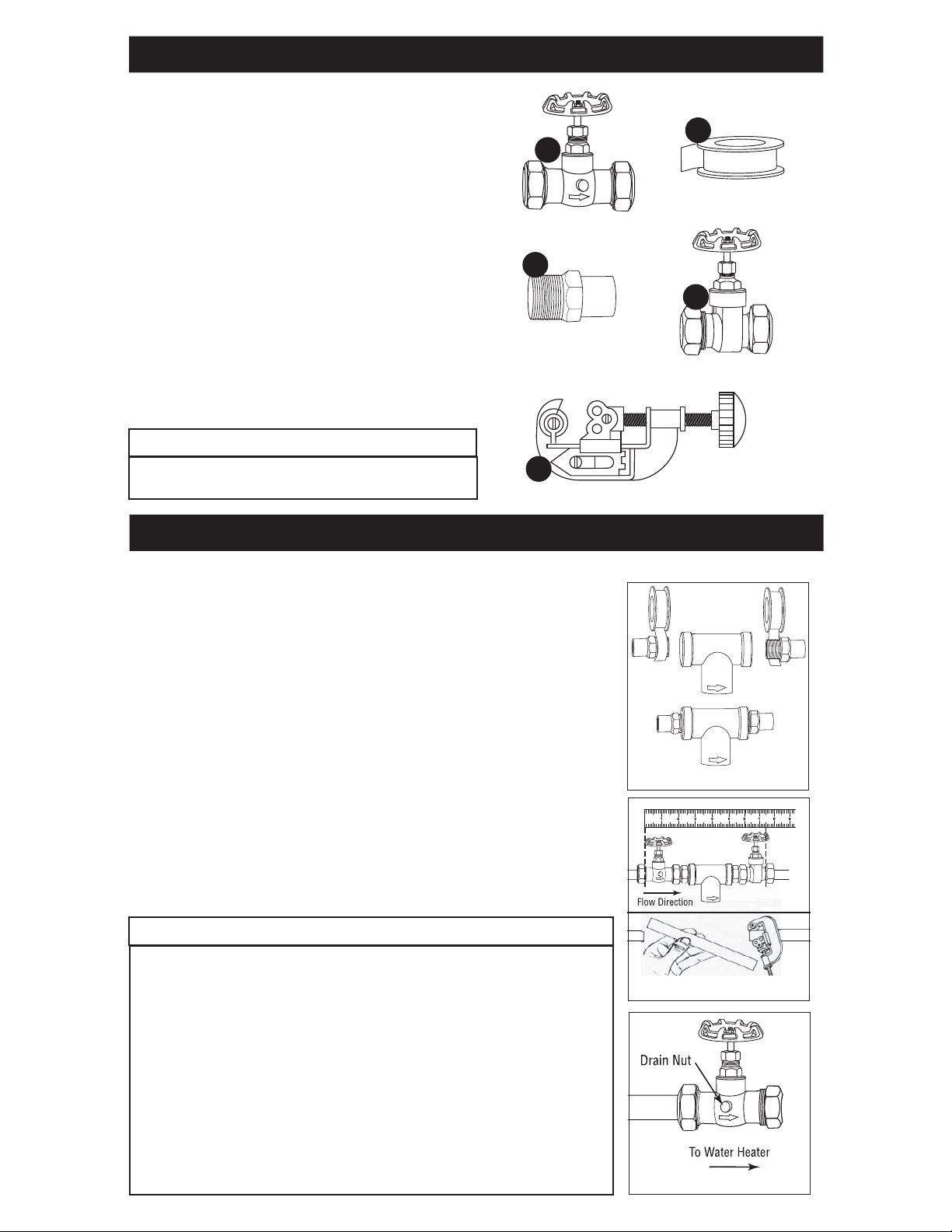
Tools and Parts Required
(not included):
1) One 3/4” Stop & Waste Valve (Compression Type)
2) PTFE Tape
3) Two 3/4” Male x 3/4” Street Adapters
4) One 3/4” Compression Gate Valve
5) Pipe Cutter
2
1
Identify all parts as shown in diagram. Read all instructions
carefully before attempting to start installation. The existing
shut-off valve remains in place and still acts as the cold water
shut-off.
This filter system has 3/4” connections. The AP430SS can
be adapted to various pipe sizes by using reducing adapter on
either end. Installation fittings can be sweated or threaded.
Use galvanized fittings for installation on galvanized pipe.
3
IMPORTANT NOTES
• Allow a minimum of 2” (5.1 cm) clear space under
fi lter to facilitate cartridge change.
5
IMPORTANT INSTALLATION INSTRUCTIONS
Before starting, shut off main water supply and drain pipes.
Shut off fuel or electric power supply to water heater after water is shut off.
1. Using PTFE tape, wrap the threaded ends of the adapters and screw into both
ends of the cartridge head. Do not use pipe sealant/dope as they may contain
solvents that may deteriorate fittings. (Figure 1)
Position the flow direction arrow on the filter head for proper orientation.
The arrow on the filter head should be pointing toward the water heater.
2. Loosely fit compression fittings onto the cartridge head with adapters. Holding
the cartridge head with attached adapters up to the pipe, mark for length of pipe
to be removed. Using a pipe cutter, cut pipe. (Figure 2)
4
3. Using the valve compression fitting, attach the stop and waste valve on pipe
(before the system on the cold water side) to the water heater, with indicator arrow pointing towards the AP430SS assembly, so that drain nut can be
accessed to release pressure when changing cartridge. Be sure the drain nut is
firmly tightened. (Figure 3)
NOTICE
To reduce the risk associated with property damage due to water leakage or
fl ooding:
• Do not install on hot water supply lines. The maximum operating water
temperature of this fi lter system is 100°F (37.8°C).
• Installation and Use MUST comply with all state and local plumbing codes.
• On plastic fi ttings, never use pipe sealant or pipe dope. Use PTFE thread tape
only, pipe dope properties may deteriorate plastic.
• Do not use a torch or other high temperature sources near fi lter system,
cartridges, plastic fi ttings or plastic plumbing.
• Ensure that the location and fasteners will support the weight of the system.
• Ensure all tubing and fi ttings are secure and free of leaks.
• SHUT OFF FUEL OR ELECTRIC POWER SUPPLY TO WATER HEATER after
water is shut off.
Figure 1
Figure 2
Figure 3
IMPORTANT INSTALLATION INSTRUCTIONS (Continued)
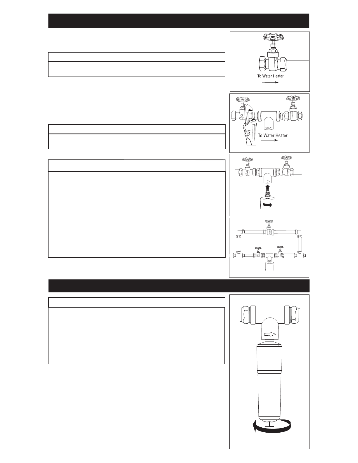
4. Using the valve compression fitting, attach the gate valve to the incoming water
supply pipe after the system. Firmly tighten compression nut. (Figure 4)
IMPORTANT NOTES
It may be necessary to slightly spread pipe ends apart in order to insert the
AP430SS head assembly with adapters into valve.
5. Tighten all compression nuts firmly, keeping the AP430SS head assembly vertical. (Figure 5)
6. Screw cartridge to the right into the AP430SS filter head. Turn on main water
supply, open valves and check for leaks. (Figure 6)
IMPORTANT NOTES
Optional: By-Pass Section can be installed around unit if desired using either
threaded or sweated fi tting. (Figure 7)
NOTICE
To reduce the risk associated with property damage due to water leakage or
fl ooding:
• Protect from freezing, remove cartridge when temperatures are expected to
drop below 40°F (4.4°C).
• Ensure all tubing and fi ttings are secure and free of leaks.
• Do not install if water pressure exceeds 125 psi (862 kPa). If your water
pressure exceeds 80 psi (552 kPa), you must install a pressure limiting
valve. Contact a plumbing professional if you are uncertain how to check
your water pressure.
• Do not install where water hammer conditions may occur. If water ham-
mer conditions exist you must install a water hammer arrester. Contact a
plumbing professional if you are uncertain how to check for this condition.
Figure 4
Figure 5
Figure 6
CARTRIDGE REPLACEMENT INSTRUCTIONS
NOTICE
To reduce the risk of water leakage of fl ooding, and to ensure optimal fi lter
performance:
• Change disposable fi lter cartridge every 6 months or sooner if you
observe a noticable reduction in water fl ow rate.
• Failure to replace the disposable fi lter cartridge at recommended
intervals may lead to reduced fi lter performance and cracks in the fi lter
housing, causing water leakage or fl ooding.
Always have spare cartridges on hand.
1. Shut off inlet (Stop and Waste) and outlet (Compression Gate) valves. Open
drain on inlet valve, to relieve pressure in the AP430SS.
2. Unscrew the cartridge (AP431) to the left as shown in the illustration. (Figure 8)
3. Install the new cartridge, moderately hand tight. Never use tools to tighten a
cartridge.
4. Turn on inlet valve and bleed air through gate valve drain until water appears.
Then close drain, and open outlet valve.
Figure 7
Figure 8

IMPORTANT NOTES
If you are installing this AP430SS Scale Inhibition System on the cold water line feeding a water heater which already
has a build-up of scale, you may have loosened scale which could go downstream to clog valve and aerators. In this
case, a Stainless Steel Hot Water Sediment and Rust Filter should be installed on the hot water side of the heater to help
trap and contain this scale.
Aqua-Pure® Model
# AP430SS Scale
Inhibition System
Water Heater
or
Tankless System
AP2005 Stainless Steel Sediment and
REPLACEMENT PARTS
Head
6838732
O-Ring
7205738
Aqua-Pure Model # SST1HA with
Rust Water Filter (optional)
Cartridge
AP431
 Loading...