

3M 5811-C, 5811-B, 5811-B-3, 5811-B-2, 5811-C-3 Installation Instructions Manual
...
Industrial Loadbreak Elbow
200 A
25 kVClass
5811 Series
Installation Instructions
1.0 General
The 3M™Industrial Loadbreak Elbow connector is a fullyshielded and insulated plug-in termination for connecting
underground cable to transformers, switching cabinets and
junctions equipped with loadbreak bushings. The elbow
connector and bushing insert comprise the essential
components of all loadbreak connections.
The coppertop (bimetal) compression connector is a
standard item to transition from the cable to the loadbreak
probe. An aluminum crimp barrel is inertia-welded to a
copper lug. The aluminum barrel makes the connector
easy to crimp and the copper lug ensures a reliable, tight,
cool operating connection with the loadbreak probe.
2.0 Installation
Cable stripping and scoring tools, available from various
tool manufacturers, are recommended for use when
installing loadbreak elbows. After preparing the cable and
installing shield adapter, the elbow housing is pushed onto
the cable. The loadbreak probe is threaded into the
coppertop connector using the supplied installation tool or
an approved equivalent. Use a shotgun stick to perform
loadmake and loadbreak operations. (See page 10 for
operating instructions.)
Kit Contents:
• Elbow Body
• Coppertop Compression Connector
• Loadbreak Probe
• Probe Installation Tool
• Silicone Lubricant
• Cold Shrink Jacketing Tube
• Mastic Strips (3 ea.)
• Ground Braid Assembly
• Constant Force Spring
• CC-3 Cable Cleaning Pads
• Installation Instructions
These instructions do not claim to cover all details or variations in the equipment, procedure, or process described, nor to provide directions for meeting every
contingency during installation, operation, or maintenance. When additional information is desired to satisfy a problem not covered sufficiently for the user’s
purpose, please contact your 3M sales representative.
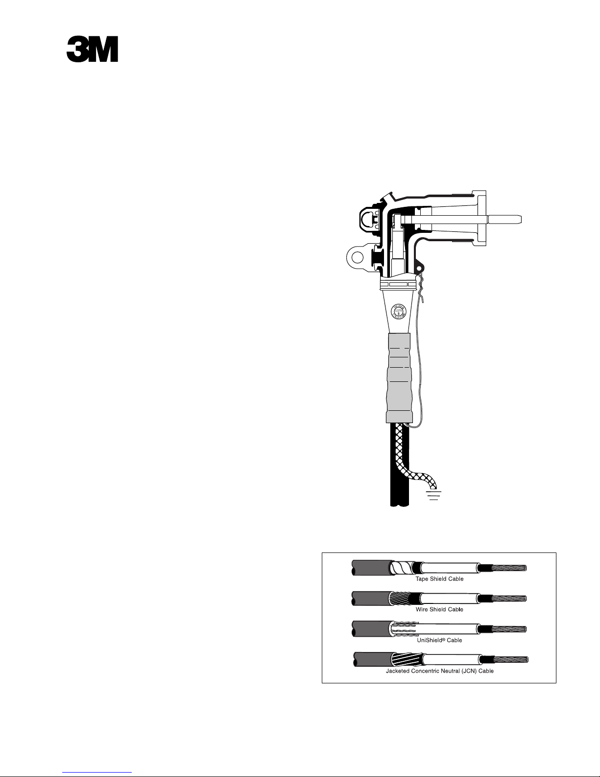
Figure 1.
Illustration of a completely assembled 25 kV loadbreak elbow,
shown on tape shielded cable.

2
78-8124-4544-9-B
Installation Notes:
• Cable description (check kit selection table on page 3
• Crimping Tool (check crimp chart on page 9)
• Location
• Installation comments

Kit No. Insulation Diameter Range 25kV (AWG/kcmil)
100% 133%
(260 mils) (320 mils)
Inches (mm) Stranded Compact/Solid Stranded Compact/Solid
5811-B* 0.700–0.910 2 2–1
5811-B-3 (17.8–23.1) 2
5811-B-2 2 1
5811-C* 1–3/0 1/0–4/0 2–1/0 2–1/0
5811-C-3 2
5811-C-2 0.850–1.100 2 1
5811-C-1 (21.6–27.9) 1 1/0 1 1/0
5811-C-1/0 1/0 2/0 1/0
5811-C-2/0 2/0 3/0
5811-C-3/0 3/0 4/0
5811-D* 4/0–250 250 2/0–4/0 2/0–4/0
5811-D-1/0 2/0
5811-D-2/0 1.040–1.250 2/0 3/0
5811-D-3/0 (26.4–31.8) 3/0 4/0
5811-D-4/0 4/0 250 4/0
5811-D-250 250
*Kit without compression connector.
Table 1. Kit Selection Table for 25 kV Class
3
78-8124-4544-9-B
4
78-8124-4544-9-B
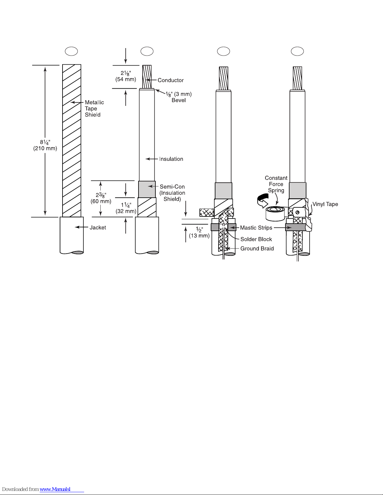
3.1 Check to be sure cable size fits within the kit range as shown in Table 1, page 3.
• Remove cable jacket for 81⁄4" (210 mm).
3.2 Remove metallic tape shield, leaving 11⁄4" (32 mm) exposed beyond cable jacket. (If necessary to prevent the tape
shield from unwinding, temporarily hold down end of shield with a wrap of vinyl electrical tape.)
• Remove semi-con (insulation shield), leaving 23⁄8" (60 mm) beyond cable jacket.
• Remove cable insulation for 21⁄8" (54 mm).
• Place a 1⁄8" (3 mm) bevel on end of cable insulation, to ease installation.
3.3 Remove white liners from one mastic strip and apply one wrap around cable jacket 1⁄2" (13 mm) from edge. Apply
with light tension. Cut off excess mastic.
• Position preformed ground braid with long leg along cable jacket as shown, with braid solder block centered on
previously applied mastic strip.
• Wrap short leg of ground braid around cable metallic tape shield for one complete wrap. Trim excess to eliminate
overlap. (Remove temporary wrap of vinyl tape if applicable.)
3.4 Secure ground braid to metallic tape shield with constant force spring. Wrap spring in same direction as ground braid,
as shown. Cinch (tighten) the last wrap of spring.
• Remove liners from second mastic strip and apply one wrap over solder block and previously applied mastic strip.
Cut off excess mastic.
• Apply two half-lapped layers of vinyl tape over mastic, constant force spring and exposed tape shield.
3.0 Preparation of Tape Shield Cable
3.1 3.2 3.3 3.4
 Loading...