

Page 1
3
Nib Removal Sander 3125
Owner’s manual
A table of contents:
a. SAFETY INFORMATION 1
b. OPERATING INSTRUCTION 3
c. SPARE PARTS INFORMATION (exploded view) 4
d. DISASSEMBLY METHOD 6
e. GUIDELINE FOR PARTS EXCHANGE 10
f. ASSEMBLY METHOD 11
Appendix. - TROUBLESHOOTING SPIDER CHART
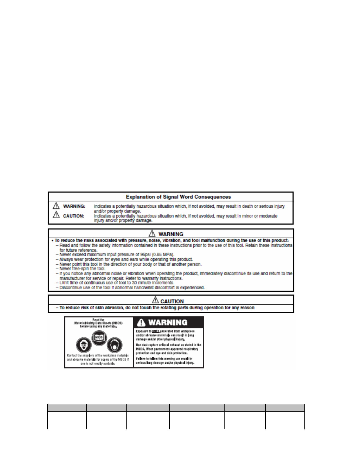
a. SAFETY INFORMATION
Please read, understand, and follow all safety information contained in these instructions prior to the use of this tool.
Retain these instructions for future reference.
Intended Use:
This tool is designed for repairing painted automobile bodies and parts as well as FRP (Fiber Reinforced Plastic) and wood. It
should not be operated in water or in an excessive wet application. All users should review this document and be trained in the
safe use of this tool.
Improper use can cause this tool to break apart and may cause injury to operators and bystanders. **
* For eye and face protection, see ANSI standard Z87.1
** For further information on coated abrasive products, consult ANSI standard B7.7, “Safety Requirement for Abrading
Material with Coated Abrasive Systems” Both are available from American Standard Institute, Inc., (212)642-4900
SPECIFICATION
Motor RPM Orbit Dia. Air flow Air Pressure Weight Pad Size
7,500 0.118 inch 5.3 SFM 58. 5 - 95.0 PSI 1.06 pounds 1.18 inch
(3 mm) (150 LPM) (0.40 - 0.65 Mpa) (0.48 kg) (30 mm)
1
Page 2

HOW TO HANDLE
• This tool is designed for repairing painted automobile bodies and parts as well as FRP (Fiber Reinforced Plastic) and
wood. It should not be operated in water or in an excessive wet application.
• Check for loose screws and missing parts before operation.
• Connect air hoses after cleaning connecting part to reduce contamination from foreign objects, dust, sand, etc.
• During inspection of each part make sure to detach air hoses.
• When connecting air hoses with an air tool, do not squeeze the trigger.
• Do not throw the tool.
• Do not drag the tool while holding the air hose.
• Do not use the tool in a non-recommended application.
• Operation without lubricants will cause rapid wear on the motor and can lead to rotation failure.
• Prior to storing lubricate the tools at a low speed to spread oil inside the motor.
• Select a dry and safe place for storage.
• Frequent cleaning of air connections will reduce contamination of the motor.
• Abnormal noise or vibration during operation indicates an immediate need for tool repair.
• If repair is necessary notify sales office or repair center from where you purchased this tool regarding inspection and
repair.
• Use only 3M-recommended replacement parts.
PRIOR TO THE OPERATION
• Keep the work area clean, orderly and free of obstacles.
• Inspect for loose parts (tool and attachment) prior to operation.
• Confirm that air pressure supply is at recommended pressure (95psi/0.65 MPa).
• When connecting to an air hose ensure a secure connection that will not loosen during operation.
• Center the abrasive on the backup pad.
• Press the abrasive securely into place.
START AND STOP
• Place the tool in contact with the work piece.
• Start the tool by pressing the lever/trigger lightly.
• Start the tool on the polishing plain during work.
• Slow the tool down before removing from the work piece.
• Remove tool at a 90 degree angle from the work piece.
• Detach air hose when the tool is not in use.
• Detach the tool from the air source when transporting.
DURING OPERATION
• Speed can be adjusted from low to high with the speed controller knob. Adjust the speed in accordance to the work being
done.
• Do not apply excessive force to the tool. Excessive force can lead to inefficient tool performance and decrease tool life.
Product Use:
or experience that 3M believes are reliable. However, many factors beyond 3M’s control can affect the use and performance of a
3M product in a particular application, including the conditions under which the 3M product is used and the time and
environmental conditions in which the product is expected to perform. Since these factors are uniquely within the user’s
knowledge and control, it is essential that the user evaluate the 3M product to determine whether it is fit for a particular purpose
and suitable for the user’s method of application.
All statements, technical information and recommendations contained in this document are based upon tests
Warranty and Limited Remedy: Unless stated otherwise in 3M’s product literature, packaging inserts or product
packaging for individual products, 3M warrants that each 3M product meets the applicable specifications at the time 3M ships the
product. Individual products may have additional or different warranties as stated on product literature, package inserts or product
packages.
3M MAKES NO OTHER WARRANTIES, EXPRESS OR IMPLIED, INCLUDING, BUT NOT LIMITED TO,
ANY IMPLIED WARRANTY OF MERCHANTABILITY OR FITNESS FOR A PARTICULAR PURPOSE OR ANY
IMPLIED WARRANTY ARISING OUT OF A COURSE OF DEALING, CUSTOM OR USAGE OF TRADE
responsible for determining whether the 3M product is fit for a particular purpose and suitable for user’s application. If the 3M
product is defective within the warranty period, your exclusive remedy and 3M’s and seller’s sole obligation will be, at 3M’s
option, to repair or replace the product or refund the purchase price.
law, 3M and seller will not be liable for any loss or damage arising from the 3M product, whether direct, indirect, special,
incidental or consequential, regardless of the legal theory asserted, including warranty, contract, negligence or strict liability.
Limitation of Liability: Except where prohibited by
. User is
Submitting a Warranty Claim
Contact your dealer when submitting a warranty claim in accordance with the restrictions listed above. Please note that all
warranty claims are subject to manufacturer’s approval. Be sure to keep your sales receipt and Product Inspection Certificate in a
safe place. These must be submitted when filing a warranty claim, within 90 days from the date of purchase.
Product Repair after Warranty Has Expired
3M does not offer repair service for product out of warranty. Please contact your dealer for the repair parts listing. For further
technical information, visit: http://solutions.3m.com/en_US/Products/ and go to Abrasives & Sandpaper link and follow the
instructions.
2
Page 3
b. OPERATING INSTRUCTION
At work
- Check to see that the workplace is in order and is appropriate for the work.
- Inspect for loose parts.
- Confirm the proper air pressure (0.4 to 0.65 MPa)
- Tighten all couplings securely so that they will not be loosened by vibration.
- Attach buffing material or paper by pressing it uniformly with the palm of hand to attach it
securely.
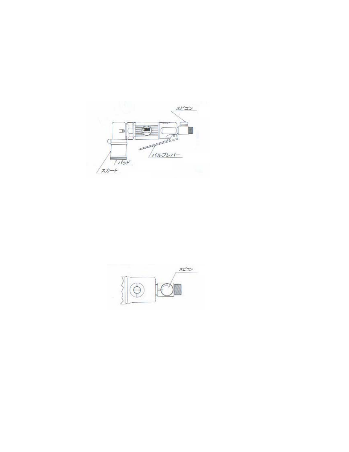
Speed control
Valve lever
Pad
Skirt
Starting and stopping
- The tool starts when the valve lever is pressed lightly. It stops when the lever is
released.
- Operate the lever as the abrasive contacts the surface to be polished. When the tool is
transported, be sure to remove the air hose.
During use
- The tool can be adjusted continuously from low to high speed by the speed control.
Adjust it according to the work.
- Do not press it onto the surface to be polished with excess force. This does not
increase efficiency, but it shortens tool life.
Speed control
After use
- ⋅Apply spindle oil to the air supply opening and operate the tool at low speed. After use,
be sure to remove the air hose and store the tool in a safe, dry place.
3
Page 4
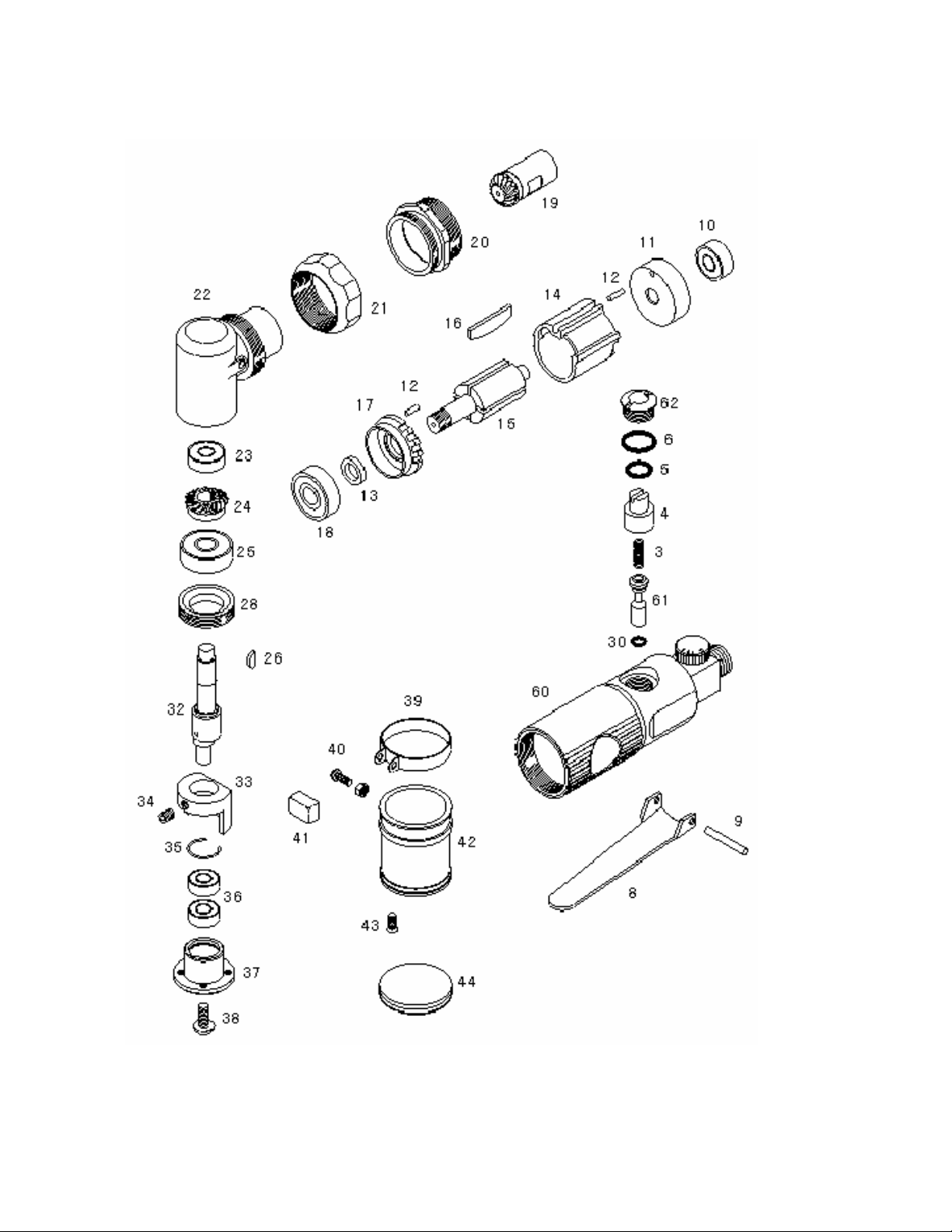
c. Spare Parts information
4
Page 5

c. Spare Parts information - continued
PARTS No. CODE ITEM QTY.
3 S3305 Spring 1
4 S3322 Air Regulator 1
5 S3323 O-Ring (P-7) 1
6 P101 O-Ring (P-10A) 1
8 S3401 Throttle Lever 1
9 S3402 Roll Pin 1
10 696ZZ Bearing (696ZZ) 1
11 S3326 Rear End Plate 1
12 S3411 Roll Pin 2
13 S3333 Rotor Collar 1
14 60743 Cylinder 1
15 S3329 Rotor 1
16 S3212 Rotor Blade 4
17 S3424 Front End Plate 1
18 608ZZ Bearing (608ZZ) 1
19 S3217 Pinion 1
20 S3215 Cup Lock 1
21 S3119 Cup 1
22 S3118 Angle Housing 1
23 696ZZ Bearing (696ZZ) 1
24 S3336 Gear 1
25 608ZZ Bearing (608ZZ) 1
26 S3338 H/R Key (φ8x1.5) 1
28 S3340 Clamp Nut 1
30 S3321 O-Ring (P-4) 1
32 60730 EX.Shaft 1
33 60731 Balancer 1
34 171408 Set Screw (M4x8) 1
35 60737 Snap Ring 1
36 686ZZ Bearing (686ZZ) 2
37 60732 Shoe Bearing Case 1
38 150406 Screw (M4x6) 1
39 60736 Skirt Band 1
40 110310A Screw Set 1Set
40-1 110310 Screw (M3x10) (1)
40-2 2103 Nut (M3) (1)
41 60739 Cap 1
42 60733A Skirt 1
43 130305 Screw (M3x5) 4
44 * Disc Pad
45 607381 Regulator (φ1.6) 1
60 60740 Housing 1
61 60741 Throttle Valve 1
62 60742 Valve Plug 1
*Available in 3M: Disc Pad Soft (UPC 051111-60537-0)
Disc Pad Hard (UPC 051111-20207-5)
Special tools for the repair operation – see Page 10
PARTS No. CODE ITEM QTY.
1) ST041 Clamp nut wrench 1
2) ST501 Bearing puller 1
3) ST028 Air motor disassembly punch 1
4) ST015 Needle punch 1
5) ST039 F. R. bearing case puller stand 1
6) ST040 Bearing puller stand 1
7) ST018 626 bearing punch 1
8) ST017 608 bearing punch 1
9) ST007 3mm pin punch 1
5
Page 6

d. Disassembly method
Disconnect air hose first. Disassembling the tool without disconnecting air hose is very dangerous.
1. Remove the skirt
- Remove four screws (43) from skirt (42) Hook-it side.
- Remove the screw (40) from the skirt clamp (39) and remove the skirt band.
- Remove the skirt (42).
2. Remove pad holder.
- Remove the thrust screw (38) and remove the case assembly (35-37).
3. Remove balancer
- Remove set screw (34) which holds balancer (33) and remove balancer.
6
Page 7

4. Remove parts from housing
- Place housing (60) in a vise and rotate cup (21) counterclockwise and remove the angle
housing assembly (22-32).
- Rotate the cup lock (20) counterclockwise and remove it.
5. Remove motor
- Remove motor assembly (10-19).
- Drive out rear bearing (11) using special tool and a hammer.
- Remove rear end plate. Drive out bearing (10) using special tool.
- Remove the cylinder (14).
- Remove the vanes (16).
- Hold the rotor (15) carefully. Rotate the pinion (19) counterclockwise and remove.
- Use a plastic hammer to strike the rotor axle (15).
- Remove the rotor from the front end plate.
- Remove the rotor collar (13).
- Drive out the bearing (18) from the front end plate (17) using the special tool.
7
Page 8

6. Disassemble the angle housing
- Clamp the angle housing assembly (22-32) in a vise. Rotate clamp nut (28) clockwise
and remove.
- Remove EX shaft assembly (32, 23-26) and remove cup (21).
- Use gear puller to remove gear (24) in the EX shaft assembly (32, 23-26) and remove
gear.
- Remove the half-moon key. Use gear puller on bearing (25) and remove.
7. Disassemble case
- Remove snap ring (35) and remove bearing (36) using special tool.
8
Page 9

8. Valve disassembly
- Remove plug (62). Remove regulator (4) and o-ring (5). Remove o-ring (6) from valve
plug (62). Remove valve assembly (3,2,30).
- Remove spring (3) and 0-ring (30) from valve assembly.
- Remove throttle valve (61).
9. Special tools for the repair operation (to help the disassembly)
1)
2)
3)
4)
5)
6)
7)
8) 9)
From top left :
1) ST041 Clamp nut wrench
2) ST501 Bearing puller
3) ST028 Air motor disassembly punch
4) ST015 Needle punch
Middle row:
5) ST039 F. R. bearing case puller stand
Bottom row:
6) ST040 Bearing puller stand
7) ST018 626 bearing punch
8) ST017 608 bearing punch
9) ST007 3mm pin punch3125 clamp nut tool - (see Page 5)
9
Page 10

e. Guideline for parts exchange
Parts no.
3 3305 Spring 1 When bent or damaged, or when it doesn’t
4 3322 Air regulator 1
5 3323 O ring (p-7) 2 When damaged
6 3501 O ring (P-10A) 1 When damaged
8 3401 Throttle lever 1 When deep wear marks occur in the part
9 3402 Roll pin 1 Lever hinge is worn badly
10 3465 Ball bearing
11 3326 Rear end plate 1 When bearing is loose or when other
12 3411 Roll pin 2
13 3333 Rotor collar 1
14 3210 Cylinder 1 When internal scratches cannot be
15 3329 Rotor 1 When the vane groove is worn
16 3212 Rotor blade 4
17 3424 Front end plate 1 When the bearing joint is loose or when
18 3464 Ball bearing
19 3217 Pinion 1 When the gear is damaged or heavily worn
20 3215 Cup lock 1
21 3119 Cup 1
22 3118 Angle housing 1
23 3466 Ball bearing
24 3336 Gear 1
25 3464 Ball bearing
26 3338 Half moon key
28 3340 Clamp nut 1
30 3321 O ring (P-4) 1 When damaged or it won’t seal
32 60730 EX shaft 1 When the bearing juncture is loose
33 60731 Balancer 1
34 170408 Stopper screw with
35 60737 Snap ring 1 When bent or severely deformed
36 686ZZ Bearing (686ZZ) 2 When the balls are worn and there is too
37 60732 Shoe bearing case 1 When the bearing is loose or deformed.
Figure no.
(ID number)
Part name Qty Guideline for parts exchange
work properly
that contacts the valve pin
1 Ball is worn and gap becomes big, or is
(696ZZ)
(608Z)
(696ZZ)
(608Z)
(1.5 x 8)
hexagonal hole (M4 x
8, tip of bar)
locked up
dangerous deformation is seen. If the
marks made by the rotor are not bad, it can
be repaired with paper wrap.
repaired.
When the width is −0.5 less than the
original size (7), or when the length
becomes −0.25 less than the original size
(25.4)
other dangerous damage is seen. If the
marks made by the rotor are not bad, it can
be repaired with paper wrap.
1 1) When the ball bearing is worn or seized
up. 2) There is too much play.
1 1) When the ball bearing is worn or seized
up. 2) There is too much play.
1 1) When the ball bearing is worn or seized
up. 2) There is too much play.
1
1
much play or the bearing is or locked up
10
Page 11

Parts no.
38 150406 Tras bis (M4 x 6) 1
39 60736 Skirt band 1 When the deformed or damage is found.
40-1 110310 Screw (M3 x 10) (1)
40-2 2103 Nut (M3) (1)
41 Cap 1
42 60733 Skirt 1 When cut or cracked or worn-out.
43 130305 Screw (M3 x 5) 4
44 60735
45 60738 Speed controller
60 60740 Housing 1
61 60741 Throttle Valve 1 When outer diameter is worn and air leaks
62 60742 Valve Plug 1
Figure no.
(ID number)
Part name Qty Guideline for parts exchange
φ30 x 4t pad
(exclusive product)
1 When surface flatness is lost
1 When parts become worn such as the inlet
screws
seriously from the valve pin sleeve joint
f. Assembly method
- Before assembly, clean each part and check for wear or damage. Use only proper
spare parts.
- Apply lubricant oil lightly on each part.
- Replace damaged O rings. Install O rings using grease (multipurpose grease - Military
Specifications G-46006, or equivalents).
- Assemble the parts carefully in reverse order from disassembly.
- Carefully confirm end clearance in the motor.
- Do not over-tighten the cup lock.
- When installing the angle housing, install the cap in the end of the angle housing
beforehand. Tighten the cup lock while confirming the position of the angle housing.
- Install the EX, shaft Assy., while confirming proper meshing of the gears. Never
assemble the gears to hit tooth to tooth.
- After assembly, look for loose or missing screws.
- Apply lubricant oil into the air inlet, and run the tool at a medium pressure to make sure
it rotates freely.
Repair services after Warranty period & Parts supply contact
Tool Warehouse Inc.
Contact: Jeff Houk
3410 East 42
Minneapolis, MN 55406-3333
Phone: 1-612-722-4260 Fax: 1-612-722-3415
e-mail:
sales@ToolWarehouseInc.com
3M Industrial Business Quality Direct / abrasives
Phone: 1-800-362-3550 (USA only)
3M Industrial Business Customer Response Center
900 Bush Avenue, Building 21-1W-10
St. Paul, MN 55106
Phone: 1-866-279-1235
www.3M.com/abrasives © 3M 2006
nd
Street,
11
Page 12

Trouble shooting Chart
d
No run No sound Regulator problem or constricted airline Check Regulator
Sound
Air motor rotates
(manually) Vane stuck because of dirt or oil If it won't rotate manually, service is require
Won't rotate Motor is locked up, because of dirt It is required overhaul
Rotates Rotates without Valve is dirty Press lever repeatedly
throttle lever
Deffected valve Replace valve or valve seat (O-ring)
O-ring is damaged Replace O-ring
Loaded
Won't rotate Dirt in air motor Overhaul
Overloading Reduce load
Bearings are damaged Replace bearing
Low RPM Dirt in air motor Lubricate, disassemble and clean
Overloading Reduce load
Vane is worn-out Replace the vane
Low air pressure Air compressor's capacity is too small
Air leak Tighten the connectors
Excessive vibration Excess air pressure Reduce air pressure
Parts are worn-out or damaged Replace worn-out or damaged parts
Pad is damaged Replace the pad
Boot is damaged Replace the boot
Excessive noise
High frequency Bearings are damaged Replace the bearing
Muffler is damaged or choked Replace or repair the muffler
Too much backlash in gears Ajust or replace the gears
Balancer is defect Replace the barancer
Groam noize Mechanical interference in motor Overhaul
The balancer screw is loose Tighten balancer
Shutting up Vanes are stacking Lubricate freely
Starting is unstable Mechanical interference in motor Overhaul
Balancer is defect Tighten balancer
 Loading...