

Page 1

ILP 0001
User’s Manual
Revision 1.0
3J Tech Co., Ltd.
342 Fu-Hsing N. Rd., 2F
Taipei, Taiwan
Tel: +886-2-2500 6916
info@3jtech.com.tw
3JTech (A3J Eng.), Inc.
15344 E. Valley Blvd., Suite C
City of Industry, CA 91746 USA
Tel: 1-626-934 7600
info@3jtech.com
Page 2

Revision History
Revision Date Changes
1.0 March 19,2007 First Release / Kiwi Huang
Related Documents or Files
1) ISSC ISBTM8-3 Bluetooth Module specification..
2) SI3014 silicon DAA data sheet.
3) IP568x –DS-P02-010815 modem chip set data sheet
4) BPM 0001 & ILP 0001 Instruction manual
Table of Contents
General Description Application Specification Block diagram AT
commands
Page 3

General Description
The ILP 0001 is a highly integrated, low-cost, high performance, and low-power
dissipation wireless modem. This wireless modem implements V.90 to achieve
Internet connection rates up to 56Kbps, supporting existing V.34 data mode, DTE
terminal and provide reliable connection with connection rate ranging from
300bps up to 115200bps
ISSC ISBTM8-3 Bluetooth Class1 module Transmitter power meet Class 1
requirement RF-Wireless Frequency 2400-2483.5 MHz Fully 723K bps data rate
speed RF output power -2 dBm--+16 dBm (class 1) High receiving sensitivity (-88
dBm 0.1%BER)
Application
Wireless modem.
Stand-alone modem
Internet Access.
Remote Access and control.
Page 4

Specification
. Data mode capabilities: . ITU-T V.90 . ITU-T V.34 . ITU-T V.32bis, V.32 .
ITU-T V.22bis,V.22 . ITU-T V.23, V.21 . Bell 212 . Bell 103 . V.42 error
correction (LAPM and MNP) . V.42bis and MNP class 5 data compression .
TIA/EIA 602 standard for AT command set . DTE speed up to 115200
Comply with Bluetooth Class 1 Transmitter power meet Class 1 requirement
RF-Wireless Frequency 2402-2480 MHz Fully 723K bps data rate speed RF
output power -2 dBm--+16 dBm (class 1) High receiving sensitivity (-88
dBm 0.1%BER)
ITEMS SPECIFICATION
Supply Voltage
Carrier Frequency
VDD: 3.3V+/-0.2V Regulated supply
voltage
2400MHz to 2483.5MHz( USA ,
Spain ,France)
Modulation Method GFSK,1Mbps,0.5BT Gaussian
Maximum Data Rate
Transmission Power +16dBm to –2dBm
Hopping 1600hops/sec, 1MHz channel space
Sensitivity -88dBm
Operation Temperature -10 to +60 degree
Absolute Max Supply
Voltage
Asynchronous:723.2kbps/57.6kbps
Synchronous:433.9kbps/433.9kbps
3.6V for VDD,other VDD +0.3V
Page 5
ghf
e
d
c
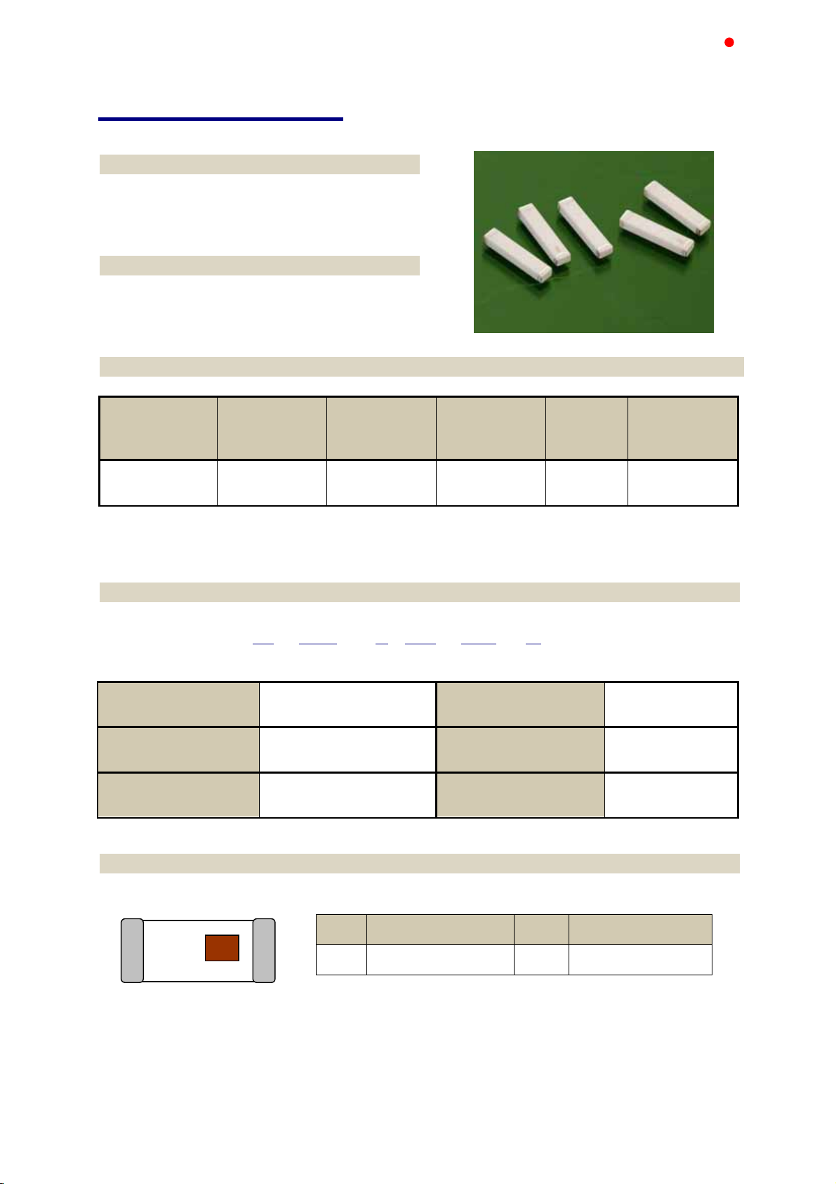
AT9520 Series
Multilayer Chip Antenna
Features
Monolithic SMD with small, low-profile and
light-weight type.
Wide bandwidth
Applications
2.4GHz WLAN, Home RF, Bluetooth Modules,
etc.
ACX
Advanced Ceramic X
Specifications
Frequency
Part Number
AT9520B2R4HAA_
Q’ty/Reel (pcs) : 1000pcs
Operating Temperature Range : -40 ~ +85
Storage Temperature Range : -40 ~ +85 oC
Power Capacity : 3W max.
Range
(MHz)
2400~2500 3.0 dBi typ. 1.0 dBi typ. 2 max.
Peak Gain
(XZ-V)
Average Gain
(XZ-V)
VSWR Impedance
50 Ω
o
C
Part Number
AT 9520 - B 2R4 HAA
Type
c
e
Material Code
AT : Antenna
B
Dimensions ( L × W )
d
Frequency Range
f
9.5× 2.0 mm
2R4=2400MHz
Specification Code
g
HAA
Packaging
h
T: Tape & Reel
B: Bulk
Terminal Configuration
d
c
No.
c
Terminal Name No. Terminal Name
Feeding Point
d
NC
Page 6
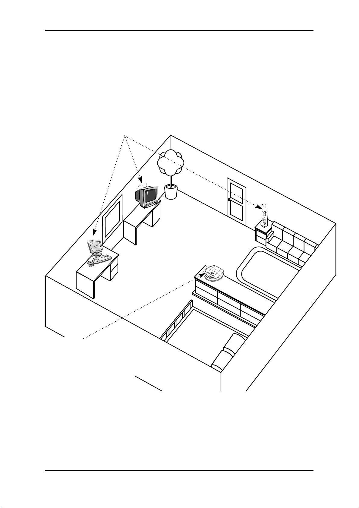
IDEAL LIFE Pod™
Location/Interferance
When using an IDEAL LIFE Pod™ to communicate information from your IDEAL LIFE BP-Manager™,
wireless radio waves are used. For maximum distance and interference-free operation, the
recommended IDEAL LIFE Pod™ location is:
Note:
While using an IDEAL LIFE Pod™, the telephone line will be in use. If the telephone line is in use
before using the your IDEAL LIFE Pod™ and you wish to use the your IDEAL LIFE Pod™ while the
telephone line is being used, the unit will not be able to make a connection and will store the
information in your IDEAL LIFE BP-Manager™ for later transmission.
IDEAL LIFE Pod™ Location/Interferance
Instruction Manual
6
• In a HIGH and CENTRAL
location with no obstructions
such as walls
• Away from electrical appliances such as a TV, personal computer
or a cordless phone
Page 7
Before You Start
To assure the correct use of the product basic safety measures should always be followed including
the precautions listed below:
• Read all information in the instruction manual and any other literature included in the box before
using the unit.
• Follow the instructions of your healthcare provider.
• Contact your physician for specific information about your blood pressure.
• Operate the unit only as intended. Do not use for any other purpose.
• This product is intended for information purposes only. It is not intended for diagnostic purposes
and is not intended and should not be used on infants or children (anyone under the age of 18).
• This is not a clinical device, but a tool for information purposes only.
• Changes or modifications not approved by IDEAL LIFE INC. may affect the proper functioning of
this product. Do not disassemble or attempt to repair the unit or components.
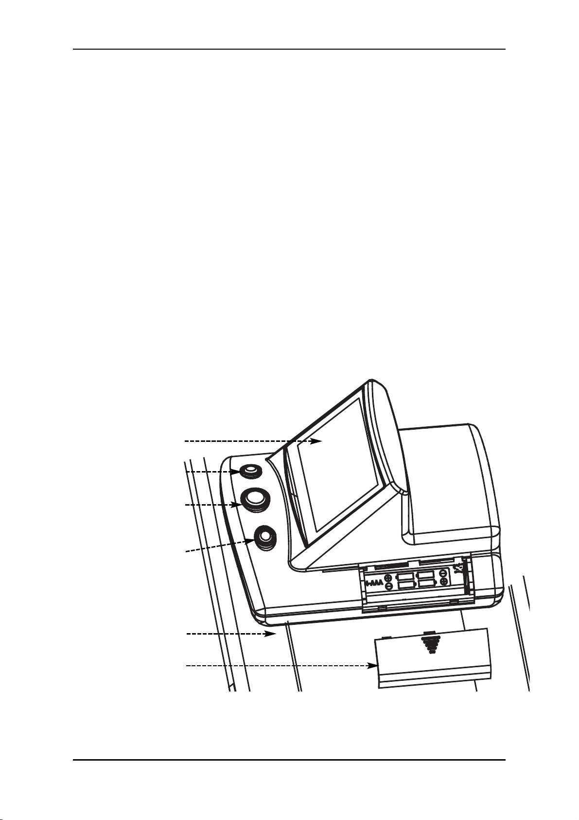
YOUR IDEAL LIFE
BP-Manager™
REMEMBER: You can stop the inflation or deflation process anytime by
pressing any button.
Before You Start
IDEAL LIFE BP-Manager™ and IDEAL LIFE Pod™
7
Display
Left “Soft” Button
START/ESCAPE
Button
Right “Soft”
Button
Upper
Arm
Cuff
Battery Cover
Page 8
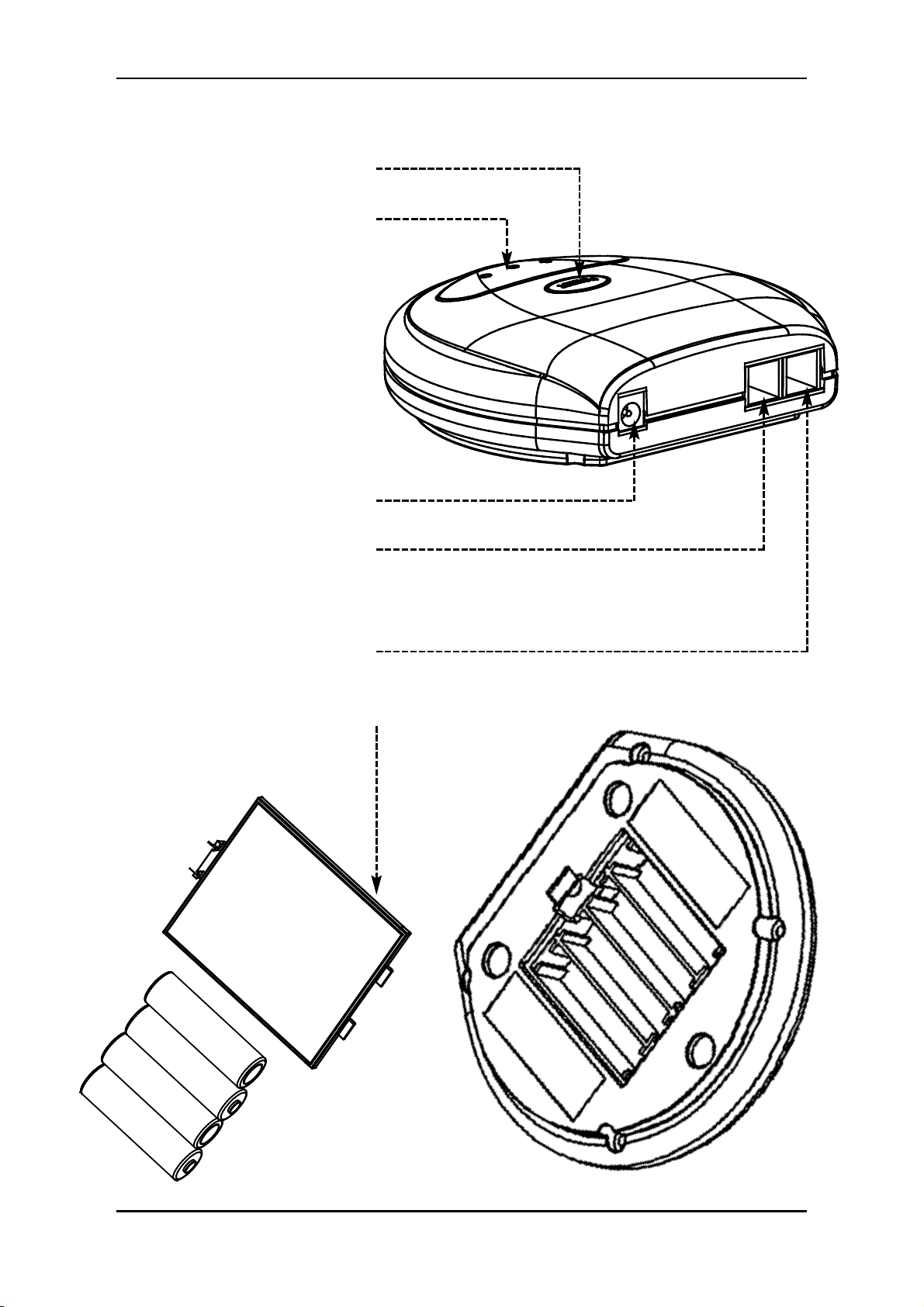
YOUR IDEAL LIFE Pod™
Before You Start
Instruction Manual
8
Power button
LED Display
AC Adapter Jack
Telephone line cord RJ11
Jack For Telephone
Connection
Telephone line cord RJ11
Jack For Line Connection
Battery Cover
Page 9

Installation
! FOR YOUR IDEAL LIFE Pod™ !
Connecting your IDEAL LIFE Pod™
USING AN RJ11 JACK
CAUTION!
• Unplug phone cord from wall before installing, plugging in an external power source, or changing
batteries.
• Never install telephone wiring during a lightning storm.
• Never touch uninsulated telephone wire or terminals, unless the telephone line has been
disconnected at the network interface.
• Use caution when installing or modifying telephone lines.
Plug one end of the telephone line cord (provided) into the jack on the back of your IDEAL LIFE Pod™
marked LINE.
Note: The IDEAL LIFE Pod™ is designed not to draw power from the
batteries when the AC adapter is in use.
Plug the other end of the telephone line cord (provided)
into a modular wall jack.
If you wish to use the same modular wall jack for your
IDEAL LIFE Pod™ and your telephone, connect the telephone
line cord from your telephone into the jack on the back of
your IDEAL LIFE Pod™ marked PHONE.
Connect the small end of the power supply into the power
AC jack on the back of the IDEAL LIFE Pod™ marked
POWER. Plug the other end into an AC power outlet.
Installation
IDEAL LIFE BP-Manager™ and IDEAL LIFE Pod™
9
Page 10

Press the POWER button on top of the IDEAL LIFE Pod™
to begin.
RECHARGING BATTERIES WITH YOUR IDEAL LIFE POD™:
• Remove the battery compartment door on the bottom of your IDEAL LIFE Pod™ by pushing gently
in the direction shown on the battery cover.
• Place the rechargeable batteries as marked.
• Replace the battery compartment door and push the compartment door shut in the opposite
direction shown on the battery cover.
• When using rechargeable batteries with your IDEAL LIFE BP-Manager™, simply place them in your
IDEAL LIFE Pod™ for 10 hours to recharge when battery status is low as indicated on your IDEAL
LIFE BP-Manager™.
Installation
Instruction Manual
10
Page 11

POWERING UP YOUR IDEAL LIFE BP-Manager™
INSTALLING THE BATTERIES (INCLUDED)
• Remove the battery compartment door on your IDEAL LIFE BP-Manager™ by lifting the battery door
using the notch
• Place the batteries as instructed
• Replace the battery compartment door and click into place
FIRST TIME POWER UP AND ACTIVATION
To use the IDEAL LIFE BP-Manager™ with your IDEAL LIFE Pod™ you must call an IDEAL LIFE customer
representative to activate. Make sure to call IDEAL LIFE before you begin. Then make sure that the
IDEAL LIFE Pod™ is connected to a telephone line cord and RJ11 jack, and “Powered ON”!
Hold down any button on your IDEAL LIFE BP-Manager™ for
3 seconds to Power up
READ THROUGH THE IDEAL LIFE INC. TERMS
AND CONDITIONS FIRST, THEN PROCEED
AND FOLLOW THE PROMPTS ON THE
SCREEN AS SHOWN HERE:
First select the appropriate language using the buttons labeled
and OK.
Then Answer the question on the following screen regarding
terms and conditions using the YES and NO labeled buttons.
To gain full advantage of all the features your IDEAL LIFE BP-
Manager™ has to offer, you will need to LINK your IDEAL LIFE
BP-Manager™ and IDEAL LIFE Pod™. To ensure that your IDEAL
LIFE BP-Manager™ and IDEAL LIFE Pod™ are LINKED properly,
you will need to call IDEAL LIFE directly to activate. To ensure
that the steps are followed correctly, you should first setup your
IDEAL LIFE Pod™, power it up, and then begin the steps of
powering up your IDEAL LIFE BP-Manager™. During your
activation call with IDEAL LIFE, an IDEAL LIFE customer representative will verify your IDEAL LIFE
BP-Manager™ and IDEAL LIFE Pod™ ID numbers so that you will be able to proceed with the last steps of
the activation process.
Installation
IDEAL LIFE BP-Manager™ and IDEAL LIFE Pod™
LANGUAGE
ENGLISH
ESPANOL
FRANCAIS
OK
PLEASE CALL
888-IDEAL-41
TO ACTIVATE
OK
11
Page 12

On the next screen, you will be asked to confirm your IDEAL LIFE Pod™ ID number, so as to ensure
that you are LINKING your IDEAL LIFE BP-Manager™ with your IDEAL LIFE Pod™ correctly. Simply use
the buttons labelled YES or NO to confirm the number. You will find the IDEAL LIFE Pod™ ID number
displayed on the bottom of the IDEAL LIFE Pod™ or on the bottom of the IDEAL LIFE Pod™ box.
Multiple IDEAL LIFE Manager™ devices can be LINKED to a single IDEAL LIFE Pod™. So to ensure that
your IDEAL LIFE BP-Manager™ is properly LINKED make sure that you identify your IDEAL LIFE Pod™
ID number.
An example screen shot is shown below.
After having called an IDEAL LIFE customer representative, you will need to verify that the correct
IDEAL LIFE Pod™ ID number is displayed on your IDEAL LIFE BP-Manager™.
• Use the YES or NO buttons to verify the IDEAL LIFE Pod™
ID number to proceed.
If the IDEAL LIFE Pod™ ID number is not correct, simply press NO and follow the on screen directions
to continue. You should verify proper setup and call an IDEAL LIFE customer representative.
If the IDEAL LIFE Pod™ ID number is correct, simply press YES to continue.
Once you've confirmed your IDEAL LIFE Pod™ ID number you will be ready to take full advantage of all
your IDEAL LIFE BP-Manager™ has to offer. For a detailed description of all the features and functions
continue to the FUNCTIONS section of this manual.
Installation
Instruction Manual
12
POD ID #:
0123456789
IS THIS CORRECT?
YES NO
Page 13

Page 14

Page 15

FCC Label
Federal Communication Commission Interference Statement
This equipment has been tested and found to comply with the limits for a Class B digital device, pursuant to Part
15 of the FCC Rules. These limits are designed to provide reasonab le protection against h armful interference in
a residential installation. This equipment generates, uses and can radiate radio frequency energy and, if not
installed and used in accordance with the instructions, may cau se harmful interference to radio co mmunications.
However, there is no guarantee that interference will not occur in a particular installation. If th is equipment doe s
cause harmful interference to radio or television r eception, which can be determined by turning the equipment off
and on, the user is encouraged to try to correct the interference by one of the following measures:
z Reorient or relocate the receiving antenna.
z Increase the separation between the equipment and receiver.
z Connect the equipment into an outlet on a circuit different from that to which the receiver is connected.
z Consult the dealer or an experienced radio/TV technician for help.
FCC Caution: Any changes or modifications not expressly approved by the party responsible for compliance could
void the user's authority to operate this equipment.
This device complies with Part 15 of the FCC Rules. Operation is subject to the following two conditions: (1) This
device may not cause harmful interference, and (2) this device must accept any interference received, includin g
interference that may cause undesired operation.
This device and its antenna(s) must not be co-located or operating in conjunction with any other antenna or
transmitter.
Page 16

ILP 0001
User’s Manual AT Command Set
Page 17

Section 1. Data Mode Command
A/ Executes Last Command
When modem receives this command, modem executes
the last command string entered. Do not conclude it by
pressing “Enter”.
A Answer Command
This command instructs the modem to go off-hook and
answer an incoming call.
Bn Communication Standard Setting
This command determines ITU-T vs. Bell standard.
B0* Selects ITU-T V.22 mode when the modem is at
1200 bits/s. (Default)
B1 Selects Bell 212A when the modem is at 1200 bits/s.
Result Codes:
OK : n = 0, 1
ERROR : Otherwise
Dn
Dial
This command instructs the modem to begin the dialing
sequence. A dial string can be up to 40 characters long.
Any digit or symbol (0-9, *, #, A, B, C, D) could be dialed
as touch-tone digits. The following may be used as dial
string modifiers:
P Pulse dialing.
T* Touch tone dialing (Default).
W Wait for second dial tone.
@ Wait for quiet answer. Wait for five seconds of
silence after dialing the number.
! Hook flash.
, Pause during dialing.
; Return to command mode.
^ Enable data calling tone transmission.
S = n Dial a telephone number previously stored using
the &Zn = x command (see the &Zn = x command
for further information). The range of n is 0,1,2.
En Echo Command
ATEn command controls whether or not the characters
entered from your computer keyboard are echoed back to
your monitor while the modem is in command mode.
E0 Disables echo to the computer.
E1* Enables echo to the computer (Default).
Result Codes:
OK: n = 0, 1
ERROR: Otherwise
Hn Hook Control
This command instructs the modem to go on-hook to
disconnect a call, or off-hook to make the phone line
busy.
H0* Modem goes on-hook (Default).
H1 Modem goes off-hook.
Result Codes:
OK: n = 0, 1
ERROR: Otherwise
In Request Identification Information
This command displays specific product information about
the modem.
I0 Returns product ID code.
I1 Display Firmware version and checksum on the
DTE.
I2 Customer Used.
I3 Returns fix ID information for application software
identification. “TP560 Data/Fax/Voice 56K Modem”
I4 Returns firmware version for data pump.
I5 Returns country code.
I6 Blacklist times
I7 Display Firmware version and date on the DTE
I8 Display Firmware version and date for data pump
I9 Return Software Speakerphone or Hardware
speakerphone
I10 Checksum
Result Codes:
n = 0, 1, 2, 3, 4, 5,6,7,8,9,10
ERROR: Otherwise
Ln Monitor Speaker Volume
This command sets speaker volume to low, medium, or
high.
L0 Select low volume.
L1 Select low volume.
L2* Select medium volume. (Default)
L3
Select high volume.
Result Codes:
OK n = 0, 1, 2, 3
ERROR Otherwise
Mn Monitor Speaker Mode
This command turns the speaker on or off.
M0 The speaker is off.
M1* The speaker is on until the modem detects the
carrier signal. (Default)
M2 The speaker is always on when modem is off-hook.
M3 The speaker is on until the carrier is detected,
except while dialing.
Result Codes:
OK n = 0, 1, 2, 3
ERROR Otherwise
Nn Modulation Selection
This command controls whether or not the local modem
performs a negotiated handshake at connection time with
the remote modem when the communication speed of the
two modems is different.
N0 When originating or answering, this is for
handshake only at the communication standard
specified by AT*In.
N1* During handshake, Highest speed is specified by
AT*In. Depend on line quality fallback to a lower
speed may occur. (Default)
Result Codes:
OK n = 0, 1
ERROR Otherwise
Page 18

On Return Online to Data Mode
O0* Exit online command mode and return to data mode
(see AT Escape Sequence, +++AT). (Default)
O1 This command issues a retrain before returning to
online data mode.
O2 This command issues a rate re-negotiation before
returning to online data mode.
Result Codes:
OK n = 0, 1, 2
ERROR Otherwise
P Select Pulse Dialing
This command configures the modem for pulse
(non-touch-tone) dialing.
Result Codes: OK
Qn Result Code Control
Result codes are informational messages sent from the
modem and displayed on your monitor.
Q0* Enables modem to send result codes to the DTE.
(Default)
Q1 Disables modem from sending result codes.
Result Codes:
OK n = 0, 1
ERROR Otherwise
T Select Tone Dialing
This command instructs the modem to send DTMF tones
while dialing.
Result Codes: OK
Vn DCE Response Format
This command controls whether result codes are
displayed as words or their numeric equivalents.
V0 Displays result codes as numeric.
V1* Displays result codes as text. (Default)
Result Codes:
OK n = 0, 1
ERROR Otherwise
Wn Result Code Option
W0 Display “CONNECT DCE speed
” without V42/MNP
extended.
W1 Display “CONNECT DTE speed
” without V42/MNP
extended.
W2* Display “CONNECT DCE speed
” with V42/MNP
extended. (Default)
W3 Display “CONNECT DTE speed
” with V42/MNP
extended.
Result Codes:
OK n = 0, 1, 2, 3
ERROR Otherwise
Xn Result Code Selection and Call Progress detection
This command enables tone detection options during
dialing procedure. As these functions are chosen, the
modem chip set result codes are also affected. Therefore,
this command is frequently used to control the modem
chip set responses and dial tone detection.
X0/X Disables monitoring of busy tones unless
forced otherwise by country requirements;
send only OK, CONNECT, RING, NO
CARRIER, ERROR, and NO ANSWER
result codes. Blind dialing is
enabled/disabled by country parameters.
If busy tone detection is enforced and
busy tone is detected, NO CARRIER will
be reported. If dial tone detection is
enforced or selected and dial tone is not
detected, NO CARRIER will be reported
instead of NO DIAL TONE. (Default)
X1 Disables monitoring of busy tones unless
forced otherwise by country requirements;
send only OK, CONNECT, RING, NO
CARRIER, ERROR, NO ANSWER, and
CONNECT XXXX(XXXX=rate). Blind
dialing is enabled/disabled by country
parameters. If busy tone detection is
enforced and busy tone is detected, NO
CARRIER will be reported instead of
BUSY. If dial tone detection is enforced or
selected and dial tone is not elected, NO
CARRIER will be reported instead of NO
DIAL TONE.
X2 Disables monitoring of busy tones unless
forced otherwise by country requirements;
send only OK, CONNECT, RING, NO
CARRIER, ERROR, NO DIAL TONE, NO
ANSWER, and CONNECT XXXX. If busy
tone detection is enforced and busy tone
is detected, NO CARRIER will be reported
instead of BUSY.
X3 Enables monitoring of busy tones; send
only OK, CONNECT, RING, NO CARRIER,
ERROR, NO ANSWER, and CONNECT
XXXX. Blind dialing is enabled/disabled by
country parameters. If dial tone detection
is enforced and dial tone is not detected,
NO CARRIER will be reported.
X4* Enables monitoring of busy tones; send all
messages. (Default)
Result Codes:
OK n = 0, 1, 2, 3, 4
ERROR Otherwise
Page 19

Zn Recall Stored Profile
This command instructs the modem chip set to go
on-hook and restore the profile saved by the last &W
command.
Z0* Reset modem and retrieve active configuration profit
from stored profit 0. (Default)
Z1 Reset modem and retrieve active configuration profit
from stored profit 1.
Result Codes:
OK n = 0, 1
ERROR Otherwise
&Cn Data Carrier Detect (DCD) Control
Data carrier detect is a signal from the modem to your
computer indicating that the carrier signal is being
received from a remote modem. DCD normally turns off
when the modem no longer detects the carrier signal.
&C0 The state of the carrier from the remote modem
is ignored. DCD circuit is always on.
&C1* DCD turns on when the remote modem's carrier
signal is detected, and off when the carrier signal
is not detected. (Default)
Result Codes:
OK n = 0, 1
ERROR Otherwise
&Dn DTR Control (Data Terminal Ready)
This command interprets how the modem responds to the
state of the DTR signal and changes to the DTR signal.
&D0 Ignore.
&D1 If the DTR signal is not detected while in online
data mode, the modem enters command mode,
issues OK result code, and remains connected.
&D2* If the DTR signal is not detected while in online
data mode, the modem disconnects. (Default)
&D3 Monitor DTR signal when an on-to-off transition
occurs, the modem performs a soft reset as if the
ATZ command was received.
Result Codes:
OK n = 0, 1, 2, 3
ERROR Otherwise
&F Load Factory Settings
This command loads the configuration stored and
programmed at the factory. This operation replaces all of
the command options and the S-register settings in the
active configuration with factory values.
&Gn V.22bis Guard Tone Control
This command determines guard tone frequency and is
only used in V.22 and V.22bis mode. This option is not
used in North America and is for international use only.
&G0* Guard tone disabled. (Default)
&G1 Sets guard tone to 550 Hz.
&G2 Sets guard tone to 1800 Hz.
Result Codes:
OK n = 0, 1, 2
ERROR Otherwise
&Kn Local Flow Control Selection
&K0 Disable flow control.
&K1 Reserved.
&K2 Reserved.
&K3* Enable RTS/CTS flow control. (Default)
&K4 Enable XON/XOFF flow control.
&K5 Enable Transparent XON/XOFF flow control.
Result Codes:
OK n = 0,1,2,3,4,5
ERROR Otherwise
&Pn Pulse Dial Make-to-Break Ratio Selection
&P0 39/61 make-to-break ratio (10 pps).
&P1
33/67 make-to-break ratio (10 pps).
&P2 39/61 make-to-break ratio (20 pps)
&P3 33/67 make-to-break ratio (20 pps)
(The number of “n” is decided by your PTT requirement.)
Result Codes:
OK n = 0,1,2,3
ERROR Otherwise
&Rn Clear To Send Signal Select
&R0 Modem turns on the Clear To Send signal when it
detects the Request To Send (RTS) signal.
&R1* Modem turns on Clear To Send signal. (Default)
Result Codes:
OK n = 0, 1
ERROR Otherwise
&Sn Data Set Ready (DSR) Option
This command selects DSR action.
&S0* DSR always ON. (Default)
&S1 DSR comes on when establishing a connection
and goes off when the connection ends.
Result Codes:
OK n = 0, 1
ERROR Otherwise
&Un Protocol Selection
&U0* Select V.PCM (Default)
&U1 Select V.34Bis/V.34
&U2 Select V.32Bis/V.22Bis
&U3 Select Bell 103 300bps
&U4 Select V21 300bps
&U5 Select V23
Result Codes:
OK n = 0,1,1,2,3,4,5
ERROR Otherwise
&V View Active Configuration and Stored Profile
This command is used to display the active profiles.
Result Codes: OK
&Wn Store Current Configuration
This command stores certain command options and
S-register values into the modem nonvolatile memory.
The ATZ command or a power up reset of the modem
restores this profile.
&W0* Stores active configuration profile in configuration
profit 0. (Default)
&W1 Stores active configuration profile in configuration
profit 1.
Result Codes:
OK n = 0,1
ERROR Otherwise
Page 20

&Yn Select Stored Profile for Power On or Reset
This command does not change the behavior of the
modem but is included for compatibility with applications
that issue the &Y0 command
&Y0* Select stored profile 0. (Default)
&Y1 Select stored profile 1.
Result Codes:
OK n = 0,1
ERROR Otherwise
&Zn = x Store Telephone Number
This command is used to store up to three dialing strings
in the modem nonvolatile memory for later dialing. The
format for the command is &Zn = stored number where n
is the location 0? to which the number should be written.
The dial string may contain up to 31 characters. The
ATDS = n command dials using the string stored in
location n.
Result Codes:
OK n = 0, 1, 2
ERROR Otherwise
*In Connect Speed Selection
*I0 Selects connect speed 1200bps
*I1 Selects connect speed 2400bps
*I2 Selects connect speed 4800bps
*I3 selects connect speed 7200bps
*I4 Selects connect speed 9600bps
*I5 Selects connect speed 12000bps
*I6 Selects connect speed 14400bps
*I7 Selects connect speed 16800bps
*I8 Selects connect speed 19200bps
*I9 Selects connect speed 21600bps
*I10 Selects connect speed 24000bps
*I11 Selects connect speed 26400bps
*I12 Selects connect speed 28800bps
*I13 Selects connect speed 31200bps
*I14* Selects connect speed 33600bps (Default)
select V.pcm
*I1 Selects connect speed 28000bps
*I2 Selects connect speed 29333bps
*I3 selects connect speed 30666bps
*I4 Selects connect speed 32000bps
*I5 Selects connect speed 33333bps
*I6 Selects connect speed 34666bps
*I7 Selects connect speed 36000bps
*I8 Selects connect speed 37333bps
*I9 Selects connect speed 38666bps
*I10 Selects connect speed 40000bps
*I11 Selects connect speed 41333bps
*I12 Selects connect speed 42666bps
*I13 Selects connect speed 44000bps
*I14 Selects connect speed 45333bps
*I15 Selects connect speed 46666bps
*I16 Selects connect speed 48000bps
*I17 Selects connect speed 49333bps
*I18 Selects connect speed 50666bps
*I19 Selects connect speed 52000ps
*I20 Selects connect speed 53333bps
*I21 Selects connect speed 54666bps
*I22* Selects connect speed 56000bps (Default)
Result Codes:
OK
ERROR Otherwise
*Gn User Abort Selection
*G0* Enables key abort feature (Default)
*G1 Disables key abort feature
Result Codes:
OK n = 0,1
ERROR Otherwise
*Hn Auto Retrain Selection
*H0 Disables auto retrain
*H1* Enables auto retrain (Default)
Result Codes:
OK n = 0,1
ERROR Otherwise
Page 21

*NCnn Country select
This command provides customers chose the country for
phone line regulation.
*NC40 Australia
*NC1 Austria
*NC2 Belgium
*NC3 Denmark
*NC4 Finland
*NC5 France
*NC6 Germany
*NC17 Greece
*NC10 Netherlands
*NC28 Iceland
*NC7 Ireland
*NC8 Italy
*NC29 Liechtenstein
*NC9 Luxembourg
*NC43 Japan
*NC26 Namibia
*NC11 Norway
*NC12 Portugal
*NC27 South Africa
*NC13 Spain
*NC14 Sweden
*NC15 Switzerland
*NC16 UK
*NC18 India
*NC19 Czech Republic
*NC20 Taiwan
*NC24 Poland
*NC25 Russia
*NC22 United States
*NC36 CTR 21 600 ohm
*NC37 CTR 21 Complex Impedance
Result Codes:
OK
ERROR Otherwise
*Tn Trellis Coding Selection
*T0 Disables Trellis coding
*T1* Enables Trellis coding (Default)
Result Codes:
OK n = 0,1
ERROR Otherwise
*On Transmission Level Selection
*O0* Selects output level -11dBm (Default)
*O1 Selects output level -12dBm
*O2 Selects output level -13dBm
*O3 Selects output level -14dBm
*O4 Selects output level -15dBm
*O5 Selects output level -16dBm
*O6 Selects output level -17dBm
*O7 Selects output level -18dBm
*O8 Selects output level -19dBm
*O9 Selects output level -20dBm
*O10 Selects output level -21dBm
*O11 Selects output level -22dBm
*O12 Selects output level -23dBm
*O13 Selects output level -24dBm
*O14 Selects output level -25dBm
*O15 Selects output level -26dBm
Result Codes:
OK n = 0 - 15
ERROR Otherwise
\Nn Error Control Mode Selection
This command determines the type of error control used
by the modem when sending or receiving data.
\N0 Normal mode.
\N1 Direct mode.
\N2 MNP or disconnect mode. The modem attempts
to connect using MNP 2-4 error control
procedures. If this fails, the modem disconnects.
This is also known as MNP reliable mode.
\N3 MNP, or buffer.
The modem attempts to connect using MNP 2-4
error control procedures. If this fails, the modem
will connect in Normal modem
\N4 V.42 without ODP & ADP phase detection, MNP
or buffer.
\N5* V.42 with ODP & ADP phase detection, MNP, or
buffer (default).
The modem attempts to connect in V.42 error
control mode. If this fails, the modem attempts to
connect in MNP mode. If this fails, the modem
connects in buffer mode and continues operation.
This is also known as V.42/ MNP auto reliable
mode.
\N6 V.42 without ODP & ADP phase detection or
disconnect. The modem attempts to connect in
V.42 error control mode. If this fails, the call will
be disconnected.
\N7 V.42 with ODP & ADP phase detection or
disconnect.
Result Codes:
OK n = 0, 1, 2, 3, 4, 5, 6,7
ERROR Otherwise
\Vn Protocol Result Code
\V0* Disable protocol result code appended to DCE
speed. (Default)
\V1 Enable protocol result code appended to DCE
speed.
Result Codes:
OK n = 0, 1
ERROR Otherwise
%Cn Data Compression Control
This command determines the operation of V.42bis and
MNP class 5 data compression. Online changes do not
take effect until a disconnection occurs first.
%C0 V.42bis/ MNP 5 disabled. No data compression.
%C1* V.42bis/ MNP 5 enabled. Data compression
enabled (Default).
Result Codes:
OK n = 0, 1
ERROR Otherwise
%Dn Blacklisting Controll
%D0 Disable blacklisting.
%D1* Enable blacklisting. (Default)
Result Codes:
OK n = 0, 1
ERROR Otherwise
Page 22

Section 2. Result Code
Long Form
0 1 2 3 4
OK 0 x x x x x
CONNECT 1 x x x x x
RING 2 x x x x x
NO CARRIER 3 x x x x x
ERROR 4 x x x x x
CONNECT 1200 5 x x x x
NO DIALTONE 6 x x
BUSY 7 x x
NO ANSWER 8 x x
CONNECT 300 9 x x x x
CONNECT 2400 10 x x x x
CONNECT 4800 11 x x x x
CONNECT 9600 12 x x x x
CONNECT 7200 13 x x x x
CONNECT 12000 14 x x x x
CONNECT 14400 20 x x x x
CONNECT 19200 21 x x x x
CONNECT 38400 22 x x x x
CONNECT 57600 23 x x x x
CONNECT 115200 24 x x x x
CONNECT 1200TX/75RX 25 x x x x
CONNECT 75TX/1200RX 26 x x x x
CONNECT BELL 300 28 x x x x
CONNECT V21 29 x x x x
( Display DCE speeds by ATW0 and ATW2 )
CONNECT 16800 15 x x x x
CONNECT 19200 16 x x x x
CONNECT 21600 17 x x x x
CONNECT 24000 21 x x x x
CONNECT 26400 30 x x x x
CONNECT 28800 31 x x x x
CONNECT 31200 32 x x x x
CONNECT 33600 33 x x x x
(V.90 mode)
CONNECT 28000 34 x x x x
CONNECT 29333 35 x x x x
CONNECT 30666 36 x x x x
CONNECT 32000 37 x x x x
CONNECT 33333 38 x x x x
CONNECT 34666 39 x x x x
CONNECT 36000 40 x x x x
CONNECT 37333 41 x x x x
CONNECT 38666 42 x x x x
CONNECT 40000 43 x x x x
CONNECT 41333 44 x x x x
CONNECT 42666 45 x x x x
CONNECT 44000 46 x x x x
CONNECT 45333 47 x x x x
CONNECT 46666 48 x x x x
CONNECT 48000 49 x x x x
CONNECT 49333 50 x x x x
CONNECT 50666 51 x x x x
CONNECT 52000 52 x x x x
CONNECT 53333 53 x x x x
CONNECT 54666 54 x x x x
CONNECT 56000 55 x x x x
Short Form n value in ATXn
Section 3. S Registers Definitions
S registers generally affect how the AT commands
perform. Contents of the registers can be displayed or
modified when the modem is in command mode.
To display the value of an S register: TYPE: ATSn?,
where n is the register number.
PRESS: Enter To modify the value of an S register:
TYPE: ATSn = r where n is the register number, and r is
the new register value.
PRESS: Enter
S0 Auto Answer Ring Number
This register determines the number of rings the modem
will count before automatically answering a call. 0 (zero)
is that asks modem don’t do automatically answer at all.
When disabled, the modem can only answer with an ATA
command.
Range: 0-255
Default: 0
Units: rings
S1 Ring Counter
This register, ring counter, is read only. The value of S1 is
incremented with each ring. If no rings occur over a 6
second interval, this register is cleared.
Range: 0-255
Default: 0
Units: rings
S2 AT Escape Character (User Defined)
This register determines the ASCII valued used for an
escape sequence. The default is the “+” character. The
escape sequence allows the modem to exit data mode
and enter command mode. Values greater than 127
disable the escape sequence.
Range: 0-255
Default: 43
Units: ASCII
S3 Command Line Termination Character (User
Defined)
This register determines the ASCII values as the carriage
return character. This character is used to end command
lines and result codes.
Range: 0-127, ASCII decimal
Default: 13 (carriage return)
Units: ASCII
S4 Response Formatting Character (User Defined)
This register determines the ASCII value used as the line
feed character. The modem uses a line feed character in
command mode when it responds to the computer.
Range: 0-127, ASCII decimal
Default: 10 (line feed)
Units: ASCII
S5 Command Line Editing Character (User Defined)
This register sets the character recognized as a
backspace and pertains to asynchronous only.
Range: 0-127, ASCII decimal
Default: 8 (backspace)
Units: ASCII
Page 23

S6 Wait Before Dialing
This register sets the length of time, in seconds, that the
modem must wait (pause) after going off-hook before
dialing the first digit. The modem always pauses for a
minimum of two seconds, even if the value of S6 is less
than two seconds. Waiting for dial tone call progress
features (W dial modifier in the dial string) will override the
value in register S6. This operation, however, may be
affected by some ATX options according to country
restrictions.
Range: 3-7
Default: 6
Units: seconds
S7 Connection Completion Timeout
This register sets the time, in seconds, that the modem
must wait before hanging up because carrier is not
detected. The timer is started when the modem finishes
dialing (originate), or goes off-hook (answer). In originate
mode, the timer is reset upon detection of an answer tone
if allowed by country restriction. The timer also specifies
the wait for silence time for the @ dial modifier in seconds.
S7 is not associated with the W dial modifier.
Range: 1-255
Default: 60
Units: seconds
S8 Comma Dial Modifier Time
This register sets the time, in seconds, that the modem
must pause when it encounters a comma (,) in the dial
command string.
Range: 1-255
Default: 2
Units: seconds
S9 Carrier Detect Response Time
Register S9 sets the time the remote modem's carrier
signal must be present for the local modem to recognize it.
This feature ensures that your modem does not mistake a
busy signal, ring, or voice for the carrier signal. The value
of this register is in tenths of a second. The default value
is 600 ms, although you can change it from 1 to 255. For
example, entering a value 13 means that the remote
modem's carrier signal must be present for 1.3 seconds
for the local modem to recognize it. Setting this value
higher increases the chances the modem will not
mistakenly identify the carrier signal.
Range: 1-255
Default: 6
Units: 0.1 seconds
S10 Automatic Disconnect Delay after Carrier Loss
This register sets the length of time, in tenths of a second,
that the modem waits before hanging up after a loss of
carrier. This allows for a temporary carrier loss without
causing the local modem to disconnect. The actual
interval the modem waits before disconnecting is the
value in register S10.
Range: 1-255
Default: 14
Units: 0.1 seconds
S11 DTMF Dialing Speed
This register determines the dialing speed which is
prefixed for each country.
Range: 50-255
Default: 95
Units: 0.001 seconds
S12 Escape Guard Time
This register sets the value (in 20 ms increments) for the
required pause after the escape sequence (default 1 s).
Range: 0-255
Default: 50
Units: 0.02 seconds
S13 Pulse Dialing Control
This register determines pulse dialing is disabled or
enabled.
ATS13=0 Disable Pulse Dialing
ATS13=1 Enable Pulse Dialing
Range: 0-1
S14 Bit-mapped Register
Bit-mapped register S14 lets you control modem echo,
responses, dialing method, and the original or answer
mode.
Bi
t Function
0=0 Do not echo command (E0)
1 Echo command (E1) – default
1 Reserved
2 Mapping to ATQn
3=0 Numeric responses (V0)
1 Verbose (Verbal) Responses (V1) – default
4,5= Mapping to AT&P
6=0 Use touch-tone dialing method (T) – default
1 Use pulse dialing method (P)
7=0 Answer incoming calls (A)
1 Originate calls (D) – default
S21 Bit-mapped Register
Bit-mapped register S21 lets you control certain data
communication control signals.
Bit
Function
0,1= x Undefined
2= Mapping to AT&R
3,4=0 Modem ignores the DTR signal (&D0)
1 Modem enters command mode after
ON-to-OFF DTR transition (&D1)
2 Modem hangs up after ON-to-OFF DTR
transition (&D2) – default
3 Modem resets after ON-to-OFF DTR transition
(&D3)
5=0 CD signal always on (&C0)
1 CD signal on when a remote carrier signal is
present (&C1) – default
6 =0 AT&S=0
1 AT&S=1
Page 24

S22 Bit mapped Register
Bit-mapped register S22 lets you control internal speaker
and the modem responses.
Bit
Function
0,1= 0 Speaker volume off (L0)
1 Low speaker volume (L1)
2 Medium speaker volume (L2) – default
3 Loud speaker volume (L3)
2,3= 0 Speaker off (M0)
1 Speaker on until carrier detected (M1) – default
2 Speaker always on (M2)
3 Speaker on until carrier detected but off during
dialing (M3)
4,5,6=0 Hayes Smart modem compatibility (X0)
1 Include CONNECT XXX responses (X1)
2 Same as 4 plus dial tone detection (X2)
3 Same as 4 plus BUSY response and blind
dialing (X3)
4 Same as 6 plus dial tone detection (X4) –
default
7 =0 Undefined
S23 Bit-mapped Register
Bit
Function
0,1,2,3= 0 0-300bps DTE data rate
1 1200bps DTE data rate
2 2400bps DTE data rate
3 4800bps DTE data rate
4 9600bps DTE data rate
5 14400bps DTE data rate
6 19200bps DTE data rate
7 34800bps DTE data rate
8 57600bps DTE data rate
9 115200bps DTE data rate
4,5= 0 Use even parity
1 Use none parity
2 Use odd parity
3 Use mark parity
6,7= 0 Mapping to AT&G
S25 Data Terminal Ready Delay
When Modem is on-line, it will ignore a Data Terminal
Ready signal lasting less than the value of this register. In
this mode, the values for this register are 0 to 255 in
hundredths of a second, and the default value is 0.05
seconds. If you will be entering synchronous mode after
dialing asynchronously, this register determines how long
the modem waits before looking for the Data Terminal
Ready signal. This lets you detach the asynchronous
terminal and connect a synchronous terminal while
remaining in the Data Mode. The default value is 5.
Range: 0-255
Default: 5
Units: 0.01 seconds
S26 Request To Send-to-Clear To Send Delay
This register affects synchronous operation only and
applies only when you are using the &R0 command. This
register determines how long the modem waits to turn on
the Clear To Send signal after a Request To Send
OFF-to-ON transition in 10 ms increment. The default
value is 1.
Range: 0-255
Default: 1
Units: 0.01 seconds
S29
Bit
Value Function
0-4 Mapping to AT*I
5-7 Mapping to AT&U
S30 Inactivity Timer
S30 specifies the length of time (in minutes) that the
modem will wait before disconnecting when no data is
sent or received. This function is only applicable to buffer
mode.
Range: 0-255
Default: 0 (Disable)
Units: minutes
S45 Timer to Control Sleep Mode
This command displays the number of seconds of
inactivity (no characters sent from the DTE, no RING) in
the off-line command state before the modem places itself
into standby mode. A value of zero prevents standby
mode.
Note: If a number between 1 and 4 is entered for this
register, it will set the value to 5, and the inactivity before
standby will be 5 s. This is done for compatibility with
previous products which allowed time-outs down to 1 s.
Range: 0, 5-255
Default: 10
S95
Bit
Value Function
0,1 Mapping to ATWn
2 Mapping to AT\V
3 Mapping to ATN
4-7 Mapping to AT*O
S96 Local Phone Status
This register tells the status of the Local Phone. It is read
only.
0 = local phone on-hook
1 = local phone off-hook
S97
Bit
Value Function
0-2 Mapping to AT\Nn
7 Mapping to AT%Cn
S98
Bit
Value Function
0,1 Mapping to AT*H
2 Mapping to AT*G
3 Mapping to AT*T
4-6 Mapping to AT&K
S99 Energy detection threshold
This register can use in Call Progress Mode (CPM) mode,
for dial tone detection threshold. This register determines
the detection threshold for Call Progress (CPM) tones.
The default value is 16.
Range : 0-255
Page 25

Section 4. Class 1 FAX Commands
The modem chip set supports FAX commands
conforming to EIA standard 578. These commands are
given here with short descriptions; complete explanations
are given in the standard, available from the Electronic
Industry Association.
FAX Command Set Summary
+FCLASS? Service class indication
+FCLASS = ? Service class capabilities
+FCLASS = n Service class selection (n=0,1,8)
+FTM = <m> Transmit FAX data
+FRM = <m> Receive FAX data
+FTH = <m> Transmit HDLC data
+FRH = <m> Receive HDLC data
+FTM = ? Check transmit FAX modulation
+FRM = ? Check receive FAX modulation
+FTH = ? Check transmit HDLC data modulation
+FRH = ? Check receive HDLC data modulation
+FMI = ? Check manufacturer identification
+FMM = ? Check product identification
+FMR = ? Check version/revision information
+FLO = ? Select Flow Control specified
+FPR = ? Select Serial Port Rate
+FCLASS? Service Class Indication
This command causes the modem to display the current
setting. The modem can operate either as a class 0 data
modem or a class 1 FAX modem.
Responses: 0 :data mode
1 if in FAX class 1
8 if in voice mode
+FCLASS = ? Service Class Capabilities
This command causes the modem to display the classes
it supports.
Typical responses:
+FCLASS = ? 0, 1, 8
+FCLASS = n Service Class Selection
This command sets the modem for class n operation,
where n is either a 0,1 or 8.
Parameters: 0, 1, 8
Default: 0
Command options:
+FCLASS = 0 Select data mode.
+FCLASS = 1 Select facsimile class 1.
+FCLASS = 8 Select voice mode.
+FTM = <m> Transmit FAX Data
This command causes the modem to transmit data at the
modulation specified by <m>. The following table shows
the values you can enter for this command and the
meaning of those values.
+FTM = 24 V.27ter 2400
+FTM = 48 V.27ter 4800
+FTM = 72 V.29 7200
+FTM = 96 V.29 9600
+FTM = 73 V.17 7200
+FTM = 74 V.17 (short train) 7200
+FTM = 97 V.17 9600
+FTM = 98 V.17 (short train) 9600
+FTM = 121 V.17 12000
+FTM = 122 V.17 (short train) 12000
+FTM = 145 V.17 14400
+FTM = 146 V.17 (short train) 14400
+FRM = <m> Receive FAX Data
This command causes the modem to receive data at the
modulation specified by <m>.
+FRM = 24 V.27ter 2400
+FRM = 48 V.27ter 4800
+FRM = 72 V.29 7200
+FRM = 96 V.29 9600
+FRM = 73 V.17 7200
+FRM = 74 V.17 (short train) 7200
+FRM = 97 V.17 9600
+FRM = 98 V.17 (short train) 9600
+FRM = 121 V.17 12000
+FRM = 122 V.17 (short train) 12000
+FRM = 145 V.17 14400
+FRM = 146 V.17 (short train) 14400
+FTH = <m> Transmit HDLC Data
This command causes the modem to transmit data
framed in the HDLC protocol at the modulation specified
by <m>.
+FTH = 3 V.21 Channel2 300
+FRH = <m> Receive HDLC Data
This command causes the modem to receive data framed
in the HDLC protocol at the modulation specified
by <m>.
+FRH = 3 V.21 Channel2 300
+FLO = <V> Flow Control Select
+FLO=0 Xon/Xoff and RTS/CTS flow control Turned off
+FLO=1 Xon/Xoff flow control
+FLO=2* RTS/CTS flow control
+FPR = <V> Serial Port Rate
Please refer A T+VPR command
Section 5. Voice Commands
+VIP Initial voice parameter
+VCID=<pmode> Caller ID
pmode=0:Disable Caller ID
pmode=1: Enable ,formatted caller report
pmode=2:Enable ,unformatted caller report
+VCID? Report current parameter
+VCID=? Queries the range that DCE support
+VDR Enable the distinctive ring feature
+VDR? Report current parameter
+VDR=? Queries the range that DCE support
+VGT Setup playback gain
+VGT? Report current parameter
+VGT=? Queries the range that DCE support
+VGR Setup record gain
+VGR? Report current parameter
+VGR=? Queries the range that DCE support
+FMI? Report manufacturer ID
+FMM? Report product information
+FMR? Report product revision
+VIT Enable inactive timer
+VIT? Report current parameter
+VIT=? Queries the range that DCE support
+VTD Set the default duration for DTMF/tone
generation in 10ms increments
+VTD? Report current parameter
+VTD=? Queries the range that DCE support
+VSD=<sds,sdi>
Page 26

sds=128 Normal level of sensitivity(-40dbm)
sds>= 128 More aggressive ;ex. sds=129
is –39dbm
sds<= 128 Less aggressive :ex sds=127
is –40dbm
sdi :Specify the amount of time the modem will
report silence to DTE
+VSD? Report cur rent parameter
+VSD=? Queries the range that DCE support
+VTS DTMF and tone generation
+VTS=? Queries the range that DCE support
ex1: AT+VTS=1 play DTMF 1 with a duration by the
+VTD command
ex2: AT+VTS=2 play DTMF 2 with a duration by the
+VTD command
ex3: AT+VTS=[1000,1300,50] play tone pair 1000Hz
and 1300hz with a duration of 50ms
ex4: AT+VTS={*,6} play DTMF * with a duration of
60ms
ex5: AT+VTS=9 play DTMF 9 with a duration by the
+VTX Enter voice playback mode
+VRX Enter voice record mode
+VSM=<cml>,<vsr>
cml=128 , select linear 8bit PCM
vsr =xx, Sample rate is always 8000
+VSM? Report current parameter
+VSM=? Queries the range that DCE support
+VPR=<rate> DTE/DCE rate will be equal 2400*rate , but
+VPR? Report current parameter
+VPR=? Queries the range that DCE support
+VLS=<pmode>
pmode=0: DCE on-hook, local phone connected
pmode=1: DCE off-hook, DCE connected to Telco
pmode=2: DCE off-hook, local phone connected
pmode=3: DCE off-hook, local phone connected
pmode=4: Speaker connected to DCE,DCE
pmode=5: Speaker connected to DEC, DCE
pmode=6: Microphone connected to DCE, DCE
pmode=7: Microphone and speaker connected ,
+VTD command
auto-baud if rate=0
to Telco.
to DCE
to Telco, DCE to local phone
on-hook(playback message)
off-hook(call screening)
on-hook (Record greeting)
DCE off-hook (speakerphone)
Section 6. AT%TTn Commands
%tt0=0 erase %TT command
%tt2=A,B,C,D Tx v34 signal parameter
A: baudrate (parameter range:0-5)
B: data rate (parameter range:1-9 if a=0)
(parameter range:2-11 if a=1)
(parameter range:2-11 if a=2)
(parameter range:2-12 if a=3)
(parameter range:2-13 if a=4)
(parameter range:2-14 if a=5)
C: Min/Exp (parameter range:0-1)
D: Preemphasise (parameter range:0-9)
example:
at%tt2=5,14,1,8
%tt3=0 : DTMF '0'
%tt3=1 : DTMF '1'
%tt3=2 : DTMF '2'
%tt3=3 : DTMF '3'
%tt3=4 : DTMF '4'
%tt3=5 : DTMF '5'
%tt3=6 : DTMF '6'
%tt3=7 : DTMF '7'
%tt3=8 : DTMF '8'
%tt3=9 : DTMF '9'
%tt3=10 : DTMF 'A'
%tt3=11 : DTMF 'B'
%tt3=12 : DTMF 'C'
%tt3=13 : DTMF 'D'
%tt3=14 : DTMF '*'
%tt3=15 : DTMF '#'
%tt3=16 : V32 9600
%tt3=17 : V32 14400
%tt3=18 : 2100HZ ANSWER TONE
%tt3=19 : 1300HZ CALLING TONE
%tt3=20 : 1100HZ CALLING TONE
%tt3=21 :
%tt3=22 : Silence
%tt4=0 : V21 Org tx mark
%tt4=1 : V21 Org tx space
%tt4=2 : V21 Ans tx mark
%tt4=3 : V21 Ans tx space
%tt4=4 : V23 Org tx mark
%tt4=5 : V23 Org tx space
%tt4=6 : V23 Ans tx mark
%tt4=7 : V23 Ans tx space
%tt4=8 : V22 org
%tt4=9 : V22bis org
%tt4=10 : V22 ans (tx guard tone if &g1 or &g2)
%tt4=11 : V22bis ans (tx guard tone if &g1 or &g2)
%tt5=0 : V27ter 2400
%tt5=1 : V27ter 4800
%tt5=2
: V29 7200
%tt5=3 : V29 9600
%tt5=4 : V17 7200 short train
%tt5=5 : V17 7200 long train
%tt5=6 : V17 9600 short train
%tt5=7 : V17 9600 long train
%tt5=8 : V17 12000 short train
%tt5=9 : V17 12000 long train
Page 27

%tt5=10 : V17 14400 short train
%tt5=11 : V17 14400 long train
 Loading...