


Table of Contents
Safety Declaration
FCC Compliance Statement________________________
Radio Frequency Interference Statement______________
Canadian DOC Notice ____________________________
Important Safety Instructions_______________________
CHAPTE
Introduction ________________
Before Installing Your Monitor _________
About Your Monitor ___________________
RGB Mode ________________________
Factory-Preset Modes _________
Packing List
Specifications ___________________
CHAPTER 2
Installing the Monitor ______
How to install the VESA mount
Control Functions _______
Description ____________________________
CHAPTER 3
Adjusting the Monitor_____
OSD Main Screen___
Auto Adjustment _____
APPENDIX
T
roubleshooting __
R 1
___________________
_____________
___________
____________
__________________
__________________________________
______________
_______________________
_____________________
________________________ 10
________ 11
________________________ 12
____________________________
___________________________ 13
______________________________
_ 4
5
_ 5
_ 6
1
2
2
3
4
4
4
8
9
12
17

FCC Compliance Statement
This device complies with part 15 of the FCC Rules. Operation is
subject to the following two conditions:
1.
This device may not cause harmful interference, and
2. This device must acc
interference that may cause undesired operation.
FCC WARNING
This equipment has been tested and found to comply with the limits for
a Class B digital device, pursuant to Part 15 of the FCC Rules. These
limits are designed to provide reasonable protection against harmful
interference in a residential installation.
This equipment generates, uses and can radiate radio frequency
energy and, if not installed and used in accordance with the
instructions, may cause harmful
However, there is no guarantee that interference will not occur in a
particular installation. If this equipment does cause harmful
interference to radio or television reception, which can be determined
by turning the e
correct the interference by one or more of the following measures:
Reorient or relocate the receiving antenna.
Increase the separation between the equipment and the
receiver.
Connect the equipment into an outlet different from that to
which the receiver is connected.
Consult the dealer or an experienced radio/TV technician for
help.
quipment off and on, the user is encouraged to try to
ept any interference received, including
interference to radio communications.
Caution:
To comply with the limits for an FCC Class B computing device,
always use the shielded signal cord supplied with t
The Federal Communications Commission warns that changes or
modifications of the unit not expressly approved by the party
responsible for compliance could void the user s authority to operate
the equipment.
his unit.
1

CE mark for Class B ITE
EN61000
EN60950/1992+A1+A2+A3+A4+A11)
Radio Frequency Interference Statement
Canadian Doc Notice
-3-
2/1995; EN61000
Warning:
This is a Class B product. In a domestic environment, this product may
cause radio interference
take adequate measures.
For Class B Computing Devices
This digital apparatus does not exceed the Class B limits for radio
noise emissions from digital apparatus as set out in the Radio
Interfer
Communications.
Le présent appareil numérique n èmet pas de bruits radioélectriques
dépassant les limites applicables aux appareils numériques de la
class B prescrites dans le Règlement sur le brouillage radio
édicté par le ministère des Communications du Canada
ence Regulation of the Canadian Department of
(Following
-3-
3/1995, EN55024/1998,
in which case the user may be required to
European standard EN55022/1998;
électrique
2

Important Safety Instructions
Please read the following instructions carefully. This manual should be
retained for future use.
1.
To clean the LCD monitor screen, make sure the monitor is in t
power off mode. Unplug the monitor from its power source before
cleaning it. Do not spray liquid cleaners directly onto the unit.
Stand away from the LCD monitor and spray cleaning solution onto a
rag. Without applying excessive pressure, clean the
slightly dampened rag.
2.
Do not place your LCD monitor near a window. Exposing the
monitor to rain, water, moisture or sunlight can severely damage it.
3. Do not place anything on top of the monitor-to
sure the cord is pla
4.
Do not apply pressure to the LCD screen. Excessive pressure may
cause permanent damage to the display.
5. Do not remove the cover or attempt to service this unit by yourself, as
you may void the warranty. Serv
performed only by an authorized technician.
6.
Safe storage of the LCD monitor is in the range of -
(20C to +60 C). Storing your LCD monitor outside this range could
result in permanent damage.
7. If any of the foll
call an authorized technician.
The power or monitor-to-PC signal cord is frayed or damaged.
Liquid has been spilled onto the monitor, or it has been exposed
to rain.
The monitor has been dropped or the case
8. Use the monitor only with the supplied adapter. In case of loss,
contact the retailer or service center.
9. If you lose the power cord, you must purchase a power cord of the
same type and configuration.
Japan
is required.
U.S.
and/or CSA approval/number(s)
Europe
0.75mm2, or equivalent.
The power cord should bear
type of cord that it is.
ced in an area where it will not be stepped on.
owing occurs, immediately unplug your monitor and
VCTF type, 3 wires or with ground-wire; T-mark approval
VW-1; 18AWG X 3C; SVT with national approval as UL
VDE/ÖVE and/or KEMA approval; H05VV-F, 3G,
he
screen with the
-PC signal cord. Make
icing of any nature should be
4°F to 140°F
has been damaged.
the name of the manufacturer and state the
3

I
NTRODUCTION
CHAPTER 1
BEFORE INSTALLING YOUR MONITOR
Read this manual carefully.
PAY ATTENTION to all Warning and Caution messages.
DO NOT use computer components not recommended by th
manufacturer.
Do not attempt to service the monitor yourself. If a problem
occurs, contact the manufacturer's authorized service center.
ABOUT YOUR MONITOR
This monitor is a microprocessor-controlled color monitor that
uses a TFT LCD panel. The monitor
Star and VESA DPMS (Display Power Management Signaling)
power management standards.
conforms to EPA Energy
e
RGB MODE
This monitor is equipped with a microprocessor that identifies
your computer's video mode and allows you to adjust the setting.
4
F
ACT
ORY-PRESET MODES
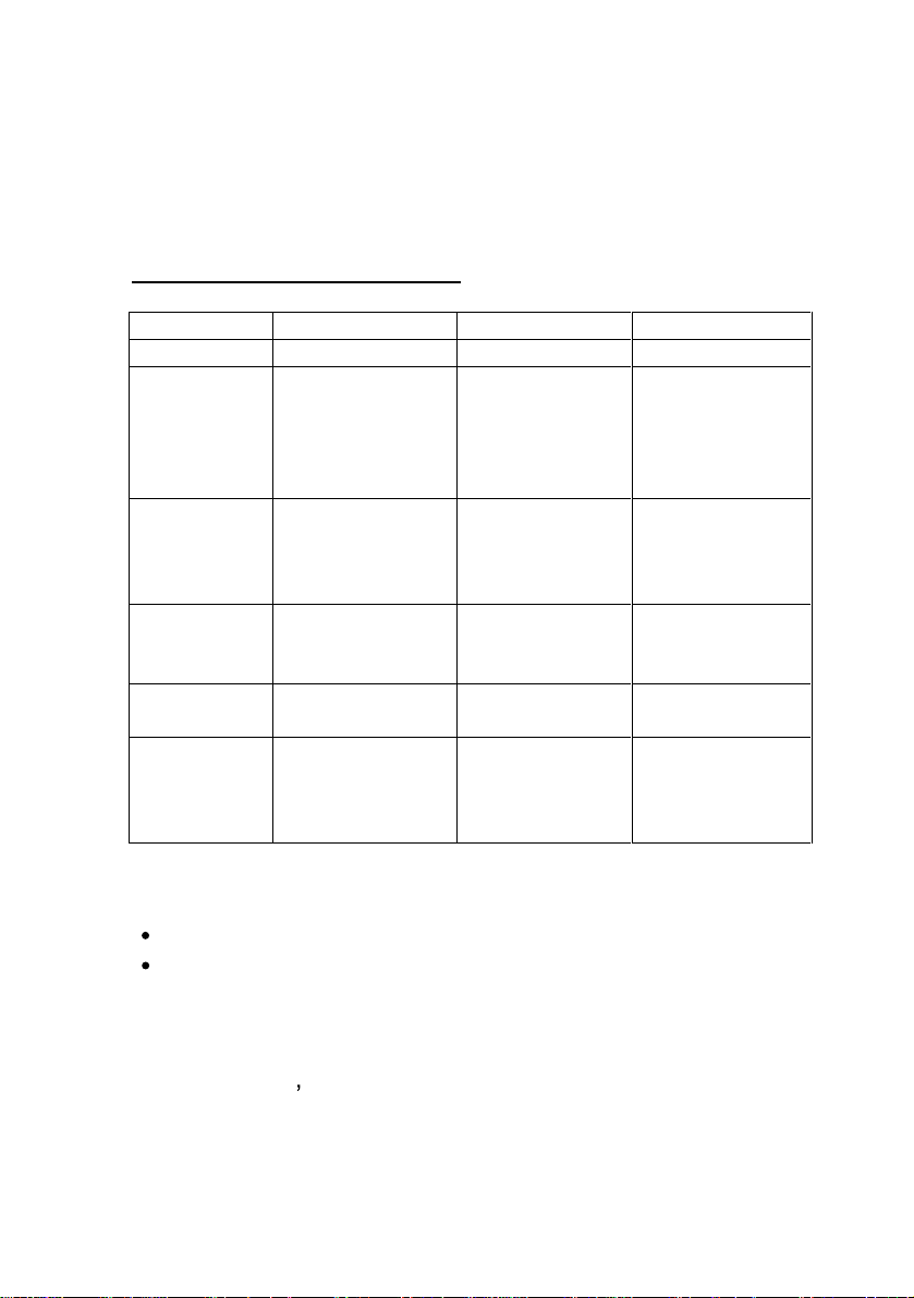
Table 1 shows standard video mode setting that has been
pre-adjusted at the factory for accurate video display. These
settings are stored in the monitor's memory.
Table 1. Factory-Preset Modes
Mode
NEC
VGA
SVGA
XGA
S
Macintosh 640x480
XGA
Resolution
640x400
640x350
720x400
640x480
640x480
640x480
800x600
800x600
800x600
800x600
1024x768
1024x768
1024x768
1280x1024
1280x1024
832x624
1024x768
1024x768
H-
24.83
31.47
31.47
31.47
37.86
37.5
35.16
37.88
48.08
46.87
48.36
56.47
60
63.98
80
35
49.7
48.78
60.241
Freq. (KHz)
V-
Freq (Hz)
56.4
70
70
60
72
75
56.3
60.3
72.2
75
60
70
75
60
75
66.7
74.55
60
74.927
P
ACKING LIST
Analog Color TFT LCD Monitor
Accessory Box:
1. RGB cable x 1
2. AC to DC adapter x 1
3. Power Cord x 1
4.
Use s manual x 1
5

S
PECIFICATIONS
17 LCD Monitor
Overall Dimension (HxWxD): 16.5 x 16.5 x 6.5 in.
(419 x 418.4 x 166 mm.)
Gross / Net Weight:
Effective Display area (H/V): 13.3 x 10.6 in.
Display colors:
Contrast ratio: 450:1
Scan Frequencies:
Horizontal
Vertical
Number of Pixels:
Pixel pitch:
Picture Tube:
Power:
Input
Consumption
Video Connector
Input
Analog RGB Signals:
Video
Sync
14.4 /12 lbs.
(337.92 x 270.34 mm.)
16 million colors (dithe
31.47K to 80KHz
60Hz to 75Hz
1280 x 1024 pixels
0.264 mm
17" TFT LCD panel
110~240VAC(a
Frequency: 48-62Hz
45Watts maximum (on)
1 Watt (
DB-15 connector
Analog RGB 0.7Vp-p/75
Separate
uto-sensing)
Power saving off mode)
ring)
6

Display Data Channel:
Comp
atibility
Operations:
User Controls
Control Type:
Compatibility:
Environmental Limits:
Operating Temp
Storage Temp.
-4
Operating Humidity 10 to 85%
Storage Humidity
Agency Approval
EMI
Energy
Safety
Saving
VESA DDC 1/2B
On/Off Power Button
Auto-adjustment,
,
,
,
button
Menu button
Digital OSD (On-Screen-Display)
IBM and compatibles, Apple
Macintosh, NEC
32 to 104
to 140
without Condensation
10 to 95%
FCC-B
F ( 0
to 40C)
F (-20 to 60C)
without Condensation
EPA energy star, VESA DPMS
UL/CUL
7

CHAPTER 2
INSTALLING THE MONITOR
This monitor is equipped with an auto sensing power
supply for voltage ranging from 110~240VAC, 60/50Hz.
Confirm the line voltage designation on the rear panel of
the
monitor.
Follow these steps to install the monitor:
1. Before you connect the cables, make sure that the
monitor and the system unit power switches are OFF.
2.
Plug one end of the 15-pin signal cable to the monitor
and the other end to the video signal connec
rear of the system. Tighten the two screws on the cable
connector on both ends. Otherwise, the screen will be
abnormal and the LED light will flash yellow (and not
the normal green color).
3.
Connect the power to the monitor through the AC/DC
adap
ter.
4. Connect the power cord on the AC outlet as shown
below.
tor at the
8

How to install the VESA mount:
Please see the below drawing.
1. First, find the slide on the stand.
2. Push the slide to the right side as step 2
3. Rotate the stand and let the stand horizontall
Now you will find the 4 holes to fix the VESA 100mm mount.
y as panel.
9

CONTROL FUNCTIONS
The control functions of the monitor are located on a dial in the
lower center portion of the front panel. They are shown in the
figure below and described in the
17 LCD Monitor
following paragraphs.
Description of control keys:
1.
2. &
3. &
4.
Menu : Enable the OSD Menu or turn off OSD
5.
Auto
Note: A hot key indicates that a particular function will work
without the need to activate the On-screen display (OSD)
menu.
: Power Switch
: Cursor left/right or Volume Hot key
: Move the cursor to the Up-menu or
sub-Menu, or Brightness hot key
:
Auto adjustment (hot key)
10

D
ESCRIPTION
1.
2.
3.
4. Auto
5. Menu
: Power switch
Use the power switch to turn power ON or OFF. We
recommend t
turning on the monitor.
&: Cursor left/right
These two keys are used to move the cursor left or
right, or used to increase or decrease values for items
selected.
&
This is a hot key that automatically adjusts the phase
and position of the LCD monitor for the best view
setting.
: Move the cursor to the Up-menu or sub-Menu
: Auto-adjustment
urning your system power on first before
Press the Menu key to activate the OSD (on-screen
display) or turn off the OSD screen. After 10 secon
idle time, the OSD screen automatically turns off.
11
ds of

CHAPTER 3
ADJUSTING THE MONITOR
The LCD monitor is designed to work with a range of
compatible video adapters on the market. Due to the
possible deviations between these video adapters, you may
make
some adjustment to fit the monitor for adapter used.
ADJUSTMENT PROCEDURE
1. First, you must activate the OSD screen through
pressing the MENU key, the screen will show in the
center of screen as below: It will tell you the current
resolution and our firmw
OSD MAIN SCREEN
2.
Use the &
press
3. Use the &
step 2 to the item you want to change.
key to select the highlight item to change.
key to move to the desired item, then
key to change the setting or repeat the
are version number
4. Use the
to return
The OSD Main Menu
to the previous menu.
12

Auto Adjust Option
The Auto Adjust option lets the monitor determine and
select the settings that are most appropriate for your
system requirements.
Brightness and Contrast Adjustment
Adjusts t
Adjusts the Contrast value
(Valid only when your color temperature is set to user
mode)
Return to the previous Menu
Color Temperature Adjustmen
Enables or disables the sRGB values
he Brightness value
t
User M
ode: Changes the RGB color values
execute the white balance function
Red
change Red gain for the color temperature
Green
change Green gain for the color temperature
Blue
change Blue gain for the co
Return to the previous Menu
13
lor temperature

Sets the color temperature to 6500K
Sets the color temperature to 9300K
Return to the previous Menu
Display Quality Adjustment
Auto Adjust
use this option to a
Changes the screen viewing size
Adjusts phase tracking to reduce display flicker
Moves the whole screen right or left
Moves the whole screen up or down
Return to the previous Menu
OSD A
djustment
Restores settings to factory default values
pply automatically setting
OSD parameter setting
Sets the OSD timer
Moves the OSD menu horizontally
Moves the OSD menu vertically
14

Return to the previous Menu
S
et the graphic mode or text mode
enable the 720x400 text mode
enable the 640x400 graphic mode
Return to the previous menu
Exit the OSD screen
15

Note:
1) No video
When the monitor is ON a
video signal received, the following
message will be displayed
2) Signal out of range
When the frequency range of the signal is out of the Monitor s
specifications, (over 85HZ) the display will show the following
message
nd there is no
Out of Range
16

Appendix
T
roubleshooting Procedures
This LCD Monitor was pre-adjusted in the factory with standard
VGA timing. Due to output timing differences among various
VGA cards, you may initially experience an unstable or unclear
display when a new display mode or new VGA c
This LCD Monitor Supports Multiple VGA Modes. Refer to timing table
for a listing of the factory-preset modes supported by this LCD Monitor.
PROBLEM: There is no LCD Display
ard is selected
.
If there is no display on the LCD, please p
steps:
1. Make sure that the power indicator on the LCD Monitor
is lit, all connections are secure, and the system is
running on the correct timing. Refer to the Addendum
for information on timing.
2. Turn off the LCD Monitor and then turn
again. Press the upper Function Control button (refer
to Chapter 2) once and then press either the upper or
lower Adjustment Control button several times. If
there is still no display, press the other Adjustment
Control button several times.
3.
If step 2 doesnt work, connect your PC system to
another external CRT. If your PC System functions
properly with a CRT Monitor but it does not function
with the LCD Monitor, and the LCD Monitor s power
LED is blinking, the output timing of the PCs VGA ca
may be out of the LCDs synchronous range. Please
change to an alternate mode listed in Addendum or
replace the VGA card and repeat steps 1 and 2.
4.
If the PC doesn t function with the CRT monitor neither,
check BIOS to see if there is a dual scan settin
the display mode item. Set the BIOS display mode to
Dual Scan
display, then there may be a problem with your system.
Contact technical support.
5. If the power LED is not lit, check to see if the AC power
connector is securely connected. Verify that the AC
adapter LED is lit. If the AC adapter LED is not lit,
please contact your dealer for assistance.
or
CRT
and try again. If there is still no
erform the following
it back on
rd
g under
17

This document was created with Win2PDF available at http://www.daneprairie.com.
The unregistered version of Win2PDF is for evaluation or non-commercial use only.
 Loading...