

Page 1

Table of Contents
Operating Instructions
Operating Instructions____________________________ 1
Safety Precautions ______________________________ 2
Care and Maintenance ___________________________ 3
CHAPTER 1
Introduction ____________________________________ 4
Before Installing Your Monitor ______________________ 4
About Your Monitor ______________________________ 4
RGB Mode ____________________________________ 4
Factory-Preset Modes ___________________________ 5
Specifications __________________________________ 6
CHAPTER 2
Installing the Monitor _____________________________ 8
Follow these Steps to Install the Monitor ______________ 8
Control Functions ________________________________9
Description _____________________________________9
CHAPTER 3
Adjusting the Monitor _____________________________ 10
OSD Screen ___________________________________ 10
Adjustment Icons ________________________________ 11
APPENDIX
Troubleshooting _________________________________14
Page 2

Operating Instructions
Thank you for purchasing this high-resolution multi-scan color monitor.
Please read this guide thoroughly before installation.
FCC RADIO FREQUENCY INTERFERENCE STATEMENT
WARNING: (FOR FCC CERTIFIED MODELS)
This monitor has been tested and found compliant with the limits for a
Class B digital device, pursuant to part 15 of the FCC Rules. These
limits are designed to provide proper protection against harmful
interference to a residential installation. This monitor generates, uses,
and can radiate radio frequency energy. Harmful interference to radio
communication may result if it is not properly installed and used.
However, there is no guarantee that interference will not occur in a
particular installation. If this monitor does cause serious interference to
radio or television reception, resetting the monitor may resolve the
problem. Moreover, users are encouraged to correct interference by
doing one or more of the following:
Reposition or relocate the receiving antenna.
Move the monitor and the receiver further away from each other.
Connect the monitor into an outlet on a circuit different from that
to which the receiver is connected.
Consult your local dealer or a qualified technician.
FCC Warning:
To assure a continued FCC compliance, a user must use a grounded
power supply cord and the provided shielded video interface cable with
bonded ferrite cores. Also, any unauthorized changes or modifications
to this monitor will void the user’s authority to operate this device.
Note: If necessary, shielded interface cables and the A.C. power cord
must be used to meet the emission level limits.
EMI Certification
The Class B digital apparatus meets all requirements of the Canadian
Interference-Causing Equipment Regulation. Cet appareil numerique de class
B respecte toutes les exigences du Reglement sur Ic materiel brouilleur du
Canada.
1
Page 3

Safety Precautions
This monitor is manufactured and tested on the principle that the
user’s safety comes first. However, improper use or installation may
not only damage the monitor but endanger the user as well. As a
safety precaution, go over the following WARNINGS carefully before
installation, and keep this guide handy.
Warnings:
This monitor should be operated only at the correct power
sources indicated on the label at the rear end of the monitor. If
you are unsure of the power supply in your residence, consult
your local dealer or Electricity Supplier.
Do not try to repair the monitor yourself, as it contains no
user-serviceable parts. The monitor should only be repaired by a
qualified technician.
Do not remove the monitor cabinet. There are high-voltage parts
inside that may cause an electric shock even when the power
cord is disconnected.
Stop using the monitor if the cabinet is damaged. Have it checked
by a service technician.
Put your monitor only in a clean, dry environment. Unplug the
monitor immediately if it gets wet, and consult your service
technician.
Always unplug the monitor before cleaning it. Clean the cabinet
with a clean, dry cloth. Apply non-ammonia-based cleaner onto
the cloth, not directly onto the glass screen.
Keep the monitor away from magnetic objects, motors, TV sets,
and transformers.
Do not place heavy objects on the cable or power cord.
For PLUG CABLE EQUIPMENT, the socket outlet should be
installed near the equipment and should be easily accessible.
2
Page 4

Care and Maintenance
Care
Avoid exposing your monitor directly to sunlight or other heat
sources. Place your monitor away from the sun to reduce glare.
Put your monitor in a well-ventilated area. Do not place anything
heavy on top of your monitor.
Make certain that your monitor is installed in a clean and
moisture-free area.
Keep your monitor away from magnets, motors, transformers,
speakers, and TV sets.
Safety Tips
If smoke, an abnormal noise or an odor comes out of your
monitor, switch off the power immediately and call our service
center.
Never remove the rear cover of your monitor cabinet. The display
unit inside contains high-voltage parts and may cause an electric
shock.
Never try to repair the monitor yourself. Always call your service
center or a qualified technician to fix it.
Note: This user’s manual contains graphics and information that is for
reference purposes only and is subject to change without notice.
3
Page 5

CHAPTER 1
NTRODUCTION
I
BEFORE INSTALLING YOUR MONITOR
Read this manual carefully.
PAY ATTENTION to all Warning and Caution messages.
DO NOT use computer components not recommend by the
manufacturer.
Do not attempt to service the monitor yourself. If a problem
occurs, contact the manufacturer's authorized service center.
ABOUT YOUR MONITOR
This monitor is a microprocessor-controlled, color monitor that uses
a TFT LCD panel. The monitor conforms to EPA Energy Star and
VESA DPMS (Display Power Management Signaling) power
management standards.
RGB MODE
This monitor is equipped with a microprocessor that identifies your
computer 's video mode and allows you to adjust the setting.
4
Page 6
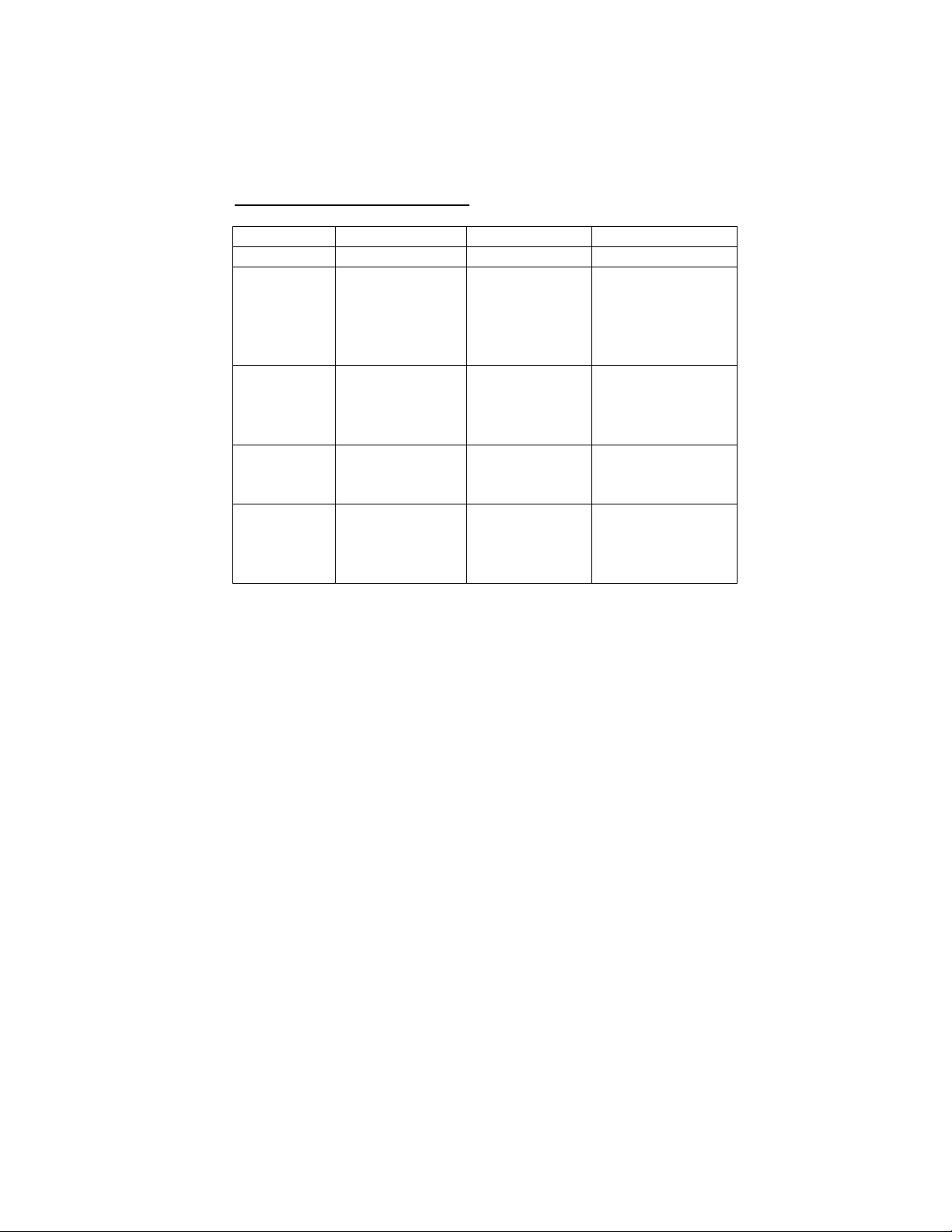
FACTORY-PRESET MODES
Table 1 shows standard video mode settings that have been
pre-adjusted at the factory for accurate video display. These
setting are stored in the monitor's memory.
Table 1. Factory-Preset Modes
Mode Resolution H-Freq.(KHz) V-Freq(Hz)
NEC 640x400 24.83 56.4
VGA 640x350
720x400
640x480
640x480
640x480
SVGA 800x600
800x600
800x600
800x600
XGA
Macintosh 640x480
1024x768
1024x768
1024x768
832x624
1024x768
1024x768
31.47
31.47
31.47
37.86
37.5
35.16
37.88
48.08
46.87
48.36
56.47
60
35
49.7
48.78
60.241
70
70
60
72
75
56.3
60.3
72.2
75
60
70
75
66.7
74.55
60
74.927
5
Page 7

SPECIFICATIONS
14.1” LCD Monitor
Overall Dimension (HxWxD): 350 x 333 x 162 mm
Shipping Weight (G/W): 5Kg
Effective Display area (H/V): 285.7 x 214.3 mm
Display colors: 262K colors
Scan Frequencies:
Horizontal 31.47KHz to 60KHz
Vertical 60Hz to 75Hz
Contrast Ratio 300:1
Response time ( Tr + Tf ) 35ms
Native Resolution 1024x768(XGA)
Pixel pitch: 0.279x0.279 mm
Power:
Input 110-240VAC
Frequency: 48-62Hz
Consumption 25 Watts maximum
1 Watt
(Power-saving OFF mode)
Video Connector: 15-pin Mini D-sub (Standard)
RGB Signals:
Video Analog RGB 0.7Vp-p/75Ω
Sync Separate
Display Data Channel:
Compatibility VESA DDC 1/2B
(auto-sensing)
(ON)
6
Page 8

Control Type: Digital
Compatibility: IBM and compatibles, Apple
Macintosh, NEC
Environmental Limits:
Operating Temp. 32°F to 106°F ( 0°C to 40°C )
Storage Temp. -4°F to 140°F ( -20°C to 60°C )
Operating Humidity 10% to 85% without condensation
Storage Humidity 10% to 95% without condensation
Agency Approval
EMI FCC-B
Energy Saving EPA energy star
Safety UL
7
Page 9
CHAPTER 2
INSTALLING THE MONITOR
The monitor is equipped with an auto sensing power supply
for voltage ranges from 110~240VAC, 60/50Hz. Confirm the
line voltage designation on the rear panel of the monitor.
FOLLOW THESE STEPS TO INSTALL THE
MONITOR
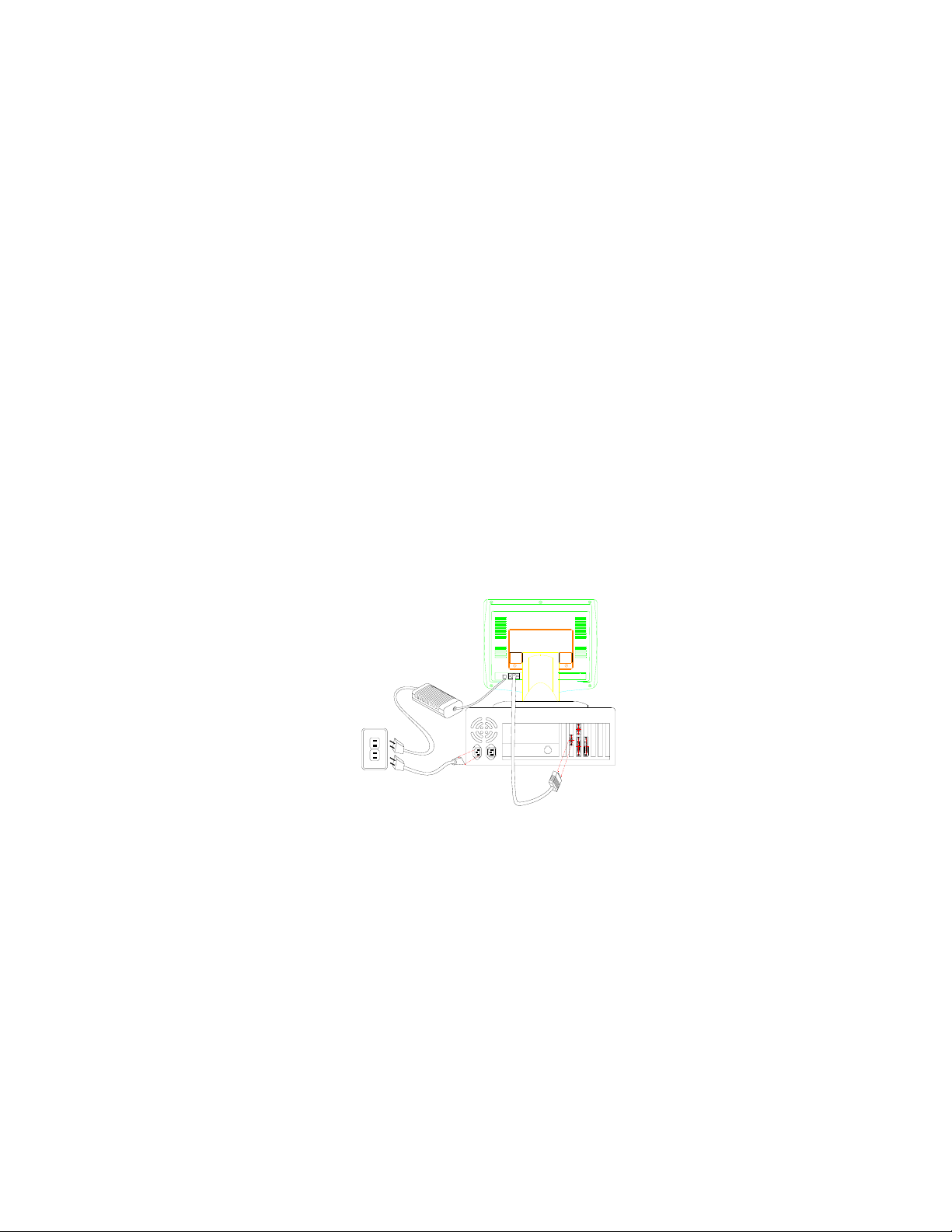
1. Before you connect the cables, make sure that the
monitor and the computers are both turned off.
2. Plug one end of the 15-pin signal cable to the monitor
and the other end to the video signal connector at the
rear of the system. Tighten the two screws on the cable
connector on both ends. Otherwise the screen will be
abnormal and the LED light will be yellow instead of the
normal green color.
3. Connect the power to the monitor through the AC/DC
adapter.
4. Connect the power cord to the AC outlet. See below.
8
Page 10
CONTROL FUNCTIONS
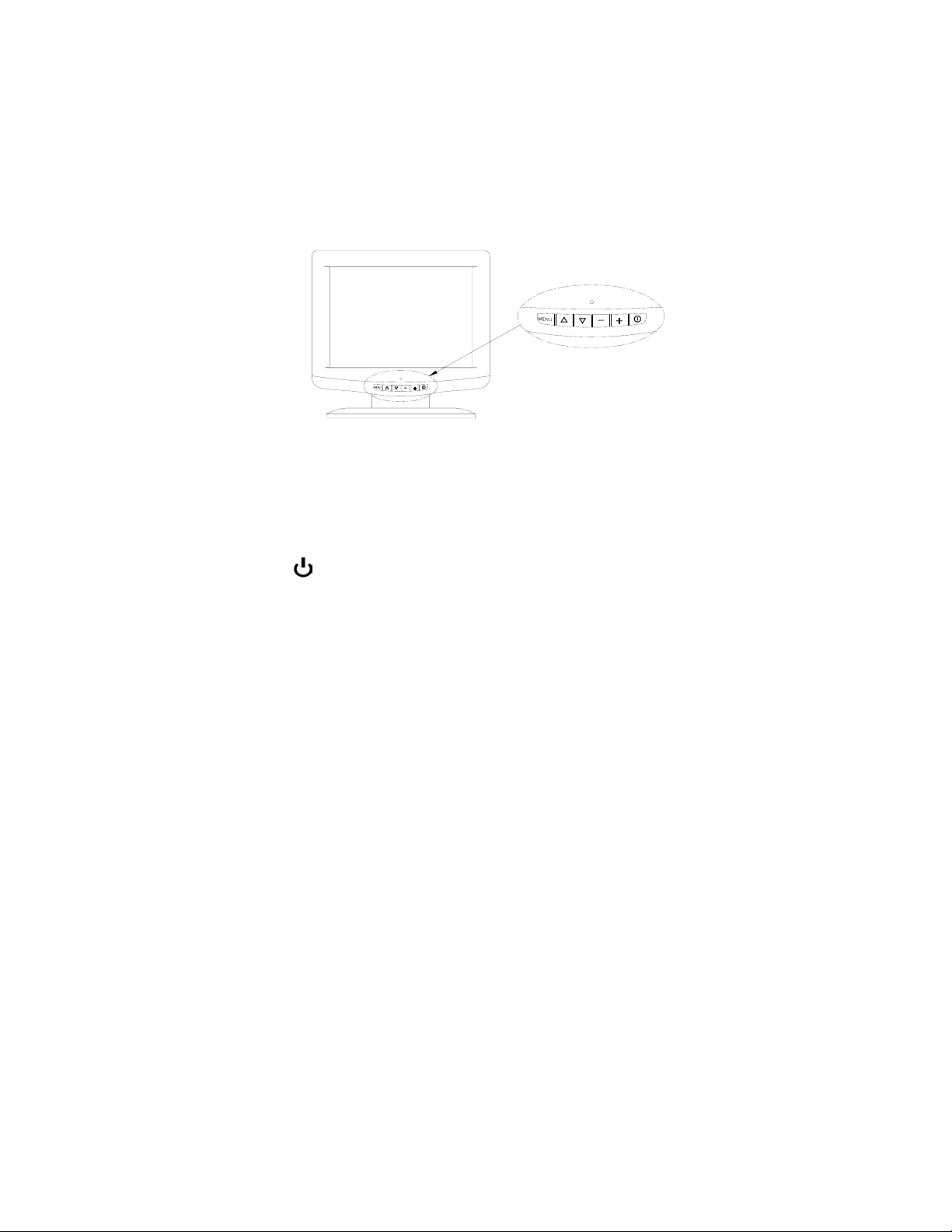
The Monitor control functions are located on the lower center
of the front part of the monitor, just below the glass. The control
functions are shown in the figure below and described in the
following paragraphs.
The control key description:
1. : Power Switch
2. ρ&σ : Move the cursor to the Up-menu or sub-Menu
3. - / + : These two keys are used to move the cursor
left or right, or used to increase or decrease
values for items selected .
4. MENU : Activates the OSD
9
Page 11
CHAPTER 3
A
DJUSTING THE MONITOR
The LCD monitor is designed to work with a range of
compatible video adapters on the market. Due to the possible
deviations between these video adapters, you may need to
make some adjustments to fit the monitor for the adapter
being used.
ADJUSTMENT PROCEDURE
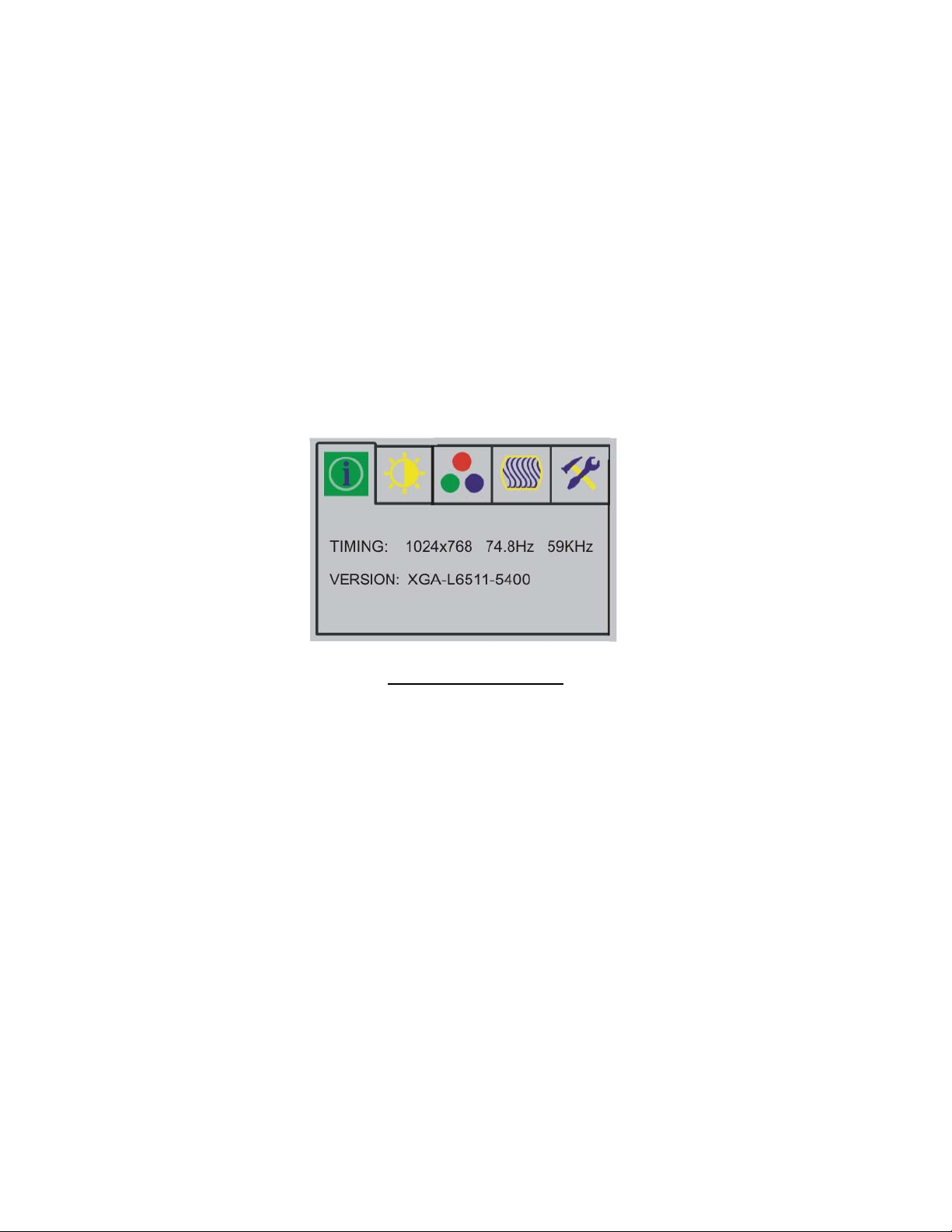
1. First, you must activate the OSD screen through pressing
the MENU key, the screen will show in the center of screen
as below:
Note: It will tell you the current resolution and our firmware
version number.
OSD MAIN SCREEN
2. Use the - / + key to move to the desired item, then press σ
key to select the highlight item to change.
3. Use the - / + key to change the setting or repeat the step
2 to the item you want to change.
4. Use the ρ to return to the previous menu.
10
Page 12
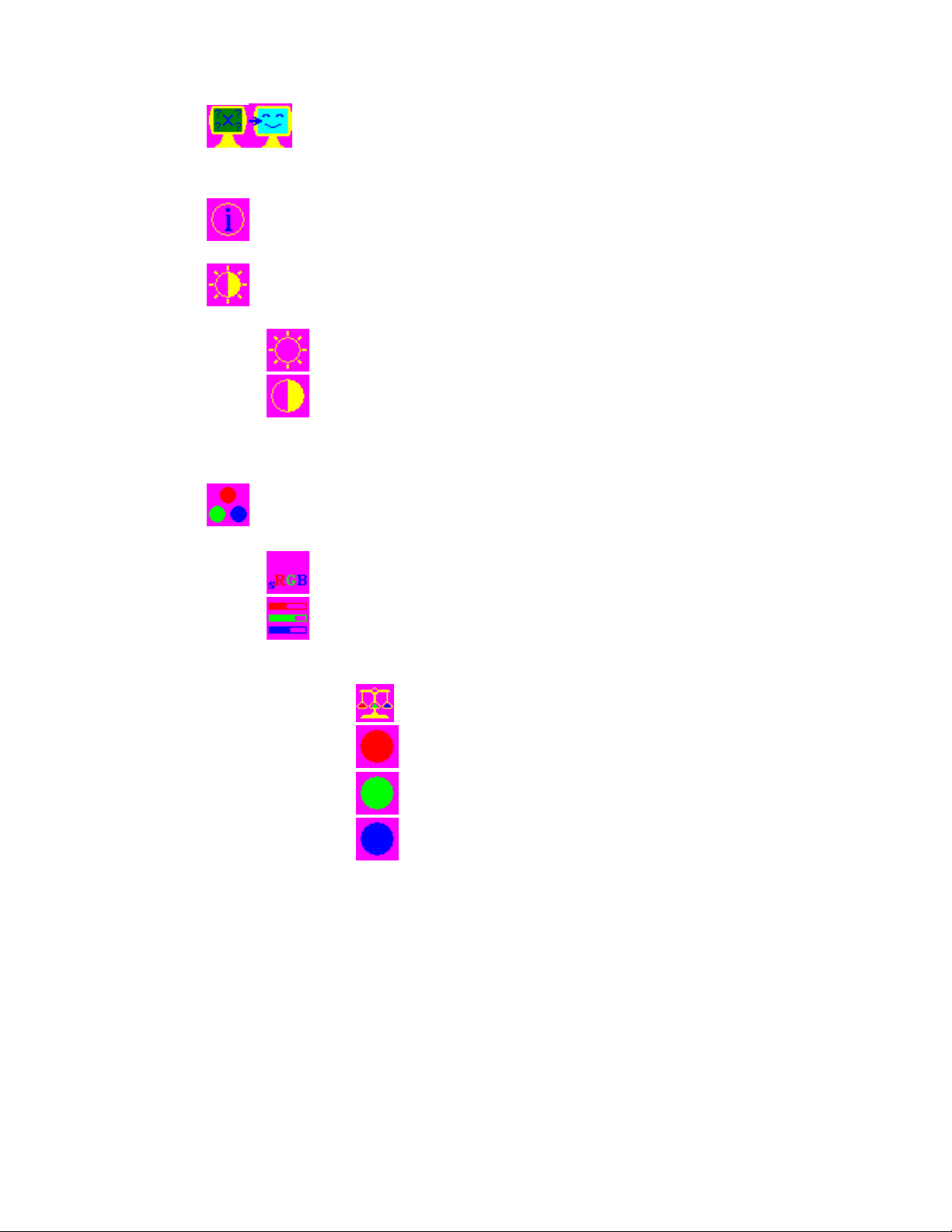
Auto Adjust Option
The Auto Adjust option lets the monitor determine
and select the settings that are most appropriate for
your system requirements.
Provides you with the current display timing information.
Brightness and Contrast Adjustment
Adjusts the Brightness value
Adjusts the Contrast value
(Valid only when your color temperature is set to user
mode)
Color Temperature Adjustment
Enables or disables the sRGB values
Users mode to let user changes the RGB color
values
Red
Green
Color balance
Blue
11
Page 13
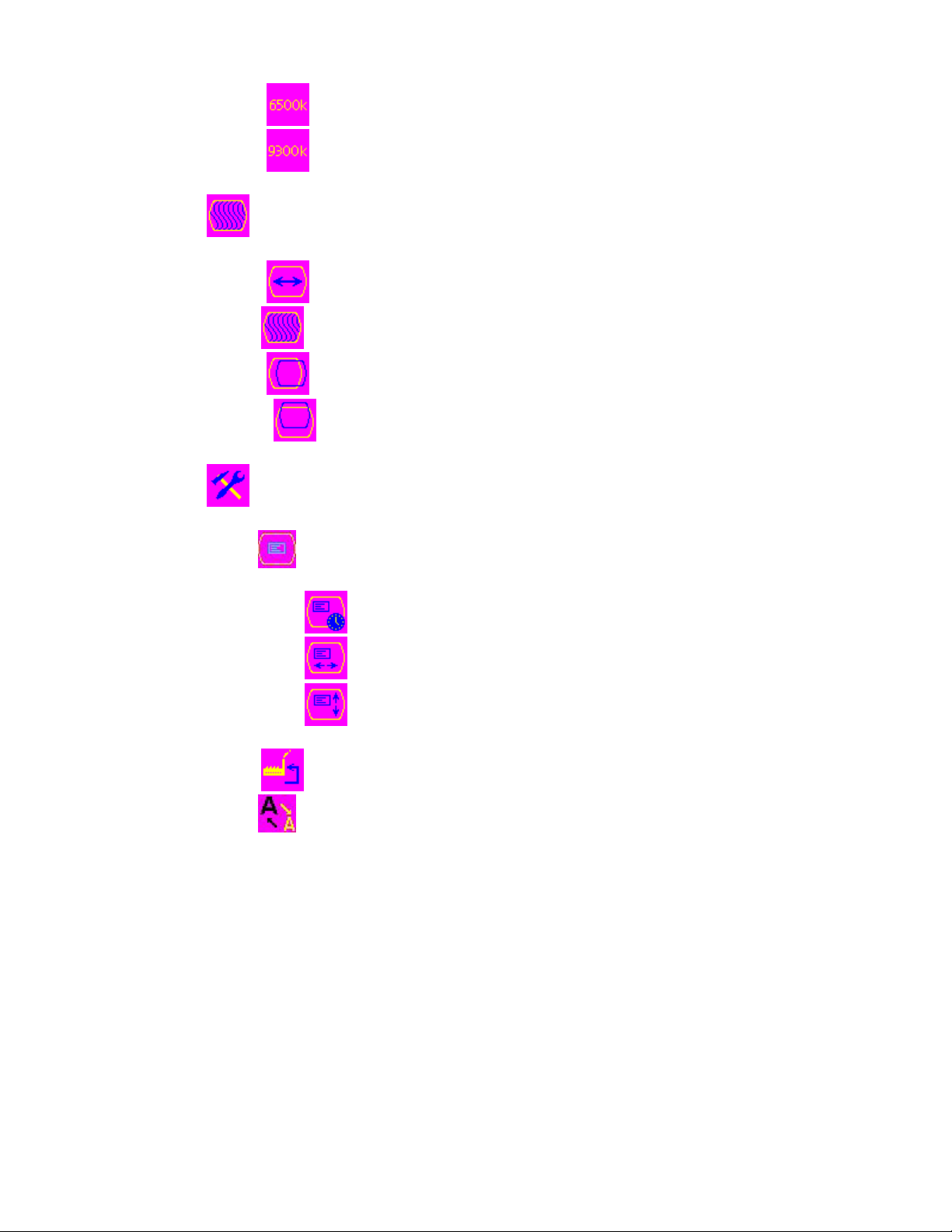
Display Adjustment
OSD Adjustment
Sets the color temperature to 6500K
Sets the color temperature to 9300K
Changes the screen viewing size
Adjusts phase tracking to reduce display flicker
Moves the whole screen right or left
Moves the whole screen up or down
OSD parameter setting
Sets the OSD timer
Moves the OSD menu horizontally
Moves the OSD menu vertically
Restores settings to factory default values
Setting the sharpness value
12
Page 14

Text/Graphic Selection
720x400 text mode
640x400 graphic mode
13
Page 15
Appendix
Troubleshooting Procedures
This LCD Monitor was pre-adjusted in the factory with standard
VGA timing. Due to output timing differences among various
VGA cards, you may initially experience an unstable or unclear
display when a new display mode or new VGA card is selected.
This LCD Monitor Supports Multiple VGA Modes. Refer to timing table
for a listing of the factory-preset modes supported by this LCD Monitor.
PROBLEM: There is no LCD Display
If there is no display on the LCD, please perform the following
steps:
1. Make sure that the power indicator on the LCD
Monitor is lit, all connections are secure, and the
system is running on the correct timing. Refer to
the Addendum for information on timing.
2. Turn off the LCD Monitor and then turn it back on
again. Press the upper Function Control button
(refer to Chapter 2) once and then press either the
upper or lower Adjustment Control button several
times. If there is still no display, press the other
Adjustment Control button several times.
3. If step 2 doesn’t work, connect your PC system to
another external CRT. If your PC System functions
properly with a CRT Monitor but it does not function
with the LCD Monitor, and the LCD Monitor’s power
LED is blinking, the output timing of the PC’s VGA
card may be out of the LCD’s synchronous range.
Please change to an alternate mode listed in
Addendum or replace the VGA card and repeat
steps 1 and 2.
4. If the PC doesn’t function with the CRT monitor
neither, check BIOS to see if there is a dual scan
setting under the display mode item. Set the BIOS
display mode to Dual Scan or CRT and try again. If
14
Page 16

there is still no display, then there may be a problem
with your system. Contact technical support.
5. If the power LED is not lit, check to see if the AC
power connector is securely connected. Verify that
the AC adapter LED is lit. If the AC adapter LED is
not lit, please contact your dealer for assistance.
15
 Loading...