

Page 1
Page 2
Page 3

Contents
Important Product Safety Instructions………………………………. 2
Antenna Installation Instruction……………………………………… 3
Cleaning the LCD Display……………………………………………. 3
Getting Started
Package Contents…………………………………………………… 4
Front View of the Product……………………..……………………. 5
Rear View of the Product………..………………………………….. 6
Remote Controls……………………………………………………… 7
Installation………….…………………………………………………. 8
OSD Functions
Source Input: TV or AV or S-Video………………………………… 12
Source Input: Component……………………………………….…. 18
Source Input: PC………………………………………..…….….…. 19
Other Information
Specifications………………………………………….…………….. 20
Troubleshooting………………………………………….………….. 21
Cleaning the Display………………………………………………… 22
Appendix
Safety Guidelines………………………………………………….… 23
Compliance Information for U.S.A……………………………….… 24
1
Page 4

IMPORTANT PRODUCT SAFETY INSTRUCTIONS
ATTENTION:
Follow and obey all warnings and instructions marked on your product. For your safety, please read
all the safety and operating instructions before you operate this product. Keep this user guide for
future reference.
1. Grounding or Polarization
Your product may be equipped with a polarized alternating-current line plug (a plug having one
blade wider than the other). This plug will fit into the power outlet only one way. This is a safety
feature. If you are unable to insert the plug fully into the outlet, try reversing the plug. If the plug
should still fail to fit, contact your electrician to replace your obsolete outlet. Do not alter the safety
purpose of the polarized plug.
2. Overloading
Do not overload wall outlets, extension cords, or integral convenience receptacles as this can
result to fire or electronic shock.
3. Power Cord Protection
Power supply cords should be routed so that they are not likely to be walked on or pinched by
items placed upon or against them. Pay particular attention to cords near plugs, convenience
receptacles, and the point where they exit from the product.
4. Ventilation
Slots and openings on the cabinet are provided for ventilation purposes.
To ensure reliable operation of the product and to protect it from overheating, these openings
must not be blocked or covered.
x Do not block the openings by placing the product on a bed, sofa, rug or other similar surface
x Do not place the product in a built-in installation such as a bookcase or rack unless proper
ventilation is provided or the manufacturer’s instruction have been adhered to.
5. Other Notices
x Avoid exposing the LCD Display to direct sunlight or high temperatures
x Avoid exposing the LCD Display to moisture or high humidity
x Do not attempt repairs yourself. Your warranty does not cover repairs or attempted repairs by
anyone not authorized by GEM
x If your LCD Display will not be used for a long period of time, unplug and remove the batteries
from the remote control
6. Precautions
Sit at least 20” away from your LCD display
Avoid touching the screen. Skin oils are difficult to remove.
Never remove the rear cover. Your LCD display contains high-voltage parts. You may be
seriously injured if you touch them.
x Avoid exposing your LCD display to direct sunlight or another heat source. Orient your LCD
display away from direct sunlight to reduce glare
x Always handle your LCD display with care when moving it
x Place your LCD display in a well-ventilated area. Do not place anything on your LCD display
that prevents heat dissipation
x Ensure the around the LCD display is clean and free of moisture
x Do not place heavy objects on the LCD display, video cable, or power cord
x If smoke, abnormal noise, or strange odor is present, immediately switch the LCD display off
and call your dealer or GEM. It is dangerous to continue using the LCD display
2
Page 5

ANTENNA INSTALLATION INSTRUCTION
1. Outdoor Antenna Grounding
If an outside antenna or cable system is connected to the product, be sure the antenna or cable
system is grounded so as to provide some protection against voltage surges and built-up static
charges. Article 810 of the National Electrical Code, ANS/NFPA 70, provides information with
regard to proper grounding of the mast and supporting structure, grounding of the lead-in wire to
an antenna discharge unit, connection to grounding electrodes, and requirements for the
grounding electrode.
2. Lightning
For added protection for this product during a lightning storm, or when it is left unattended and
unused for long periods of time, unplug it from the wall outlet and disconnect the antenna or cable
system. This will prevent damage to the product due to lightning and power-line surges. Do not
disconnect the antenna or the power cord during a heavy storm or lightning may strike while you
are holding the cable cord, causing serious injury. Turn off your LCD display and wait for the
weather to improve.
3. Power Lines
An outside antenna system should not be located in the vicinity of overhead power lines or other
electric light or power circuits. When installing an outside antenna system, extreme care should
be taken to keep from touching such power lines or circuits as contact with them may be fatal.
Cleaning the LCD Display
ʳ
x MAKE SURE THE LCD DISPLAY IS TURNED OFF
x NEVER SPRAY OR POUR ANY LIQUID DIRECTLY ONTO THE SCREEN OR CASE
To clean the screen:
1. Wipe the screen with a clean, soft, lint-free cloth. This removes dust and other particles.
2. If still not clean, apply a small amount of non-ammonia, non-alcohol based glass cleaner onto
a clean, soft, lint-free cloth, and wipe the screen.
To clean the case:
1. Use a soft, dry cloth.
2. If still not clean, apply a small amount of non-ammonia, non-alcohol based, mild non-abrasive
detergent onto a clean, soft, lint-free cloth, then wipe the surface.
Disclaimer
GEM does not recommend the use of any ammonia or alcohol-based cleaners on the LCD
display screen or case. Some chemical cleaners have been reported to damage the screen
and/or LCD display case. GEM will not be liable for damage resulting from use of any ammonia or
alcohol-based cleaners.
3
Page 6

Getting Started
Congratulations on your purchase of a GEM LCDTV display.
Important! Save the original box and all packing material for future shipping needs.
Package Contents
Your LCDTV package includes:
• LCDTV Display
• Remote Control (included battery)
• Power Cord
• User Guide
4
Page 7
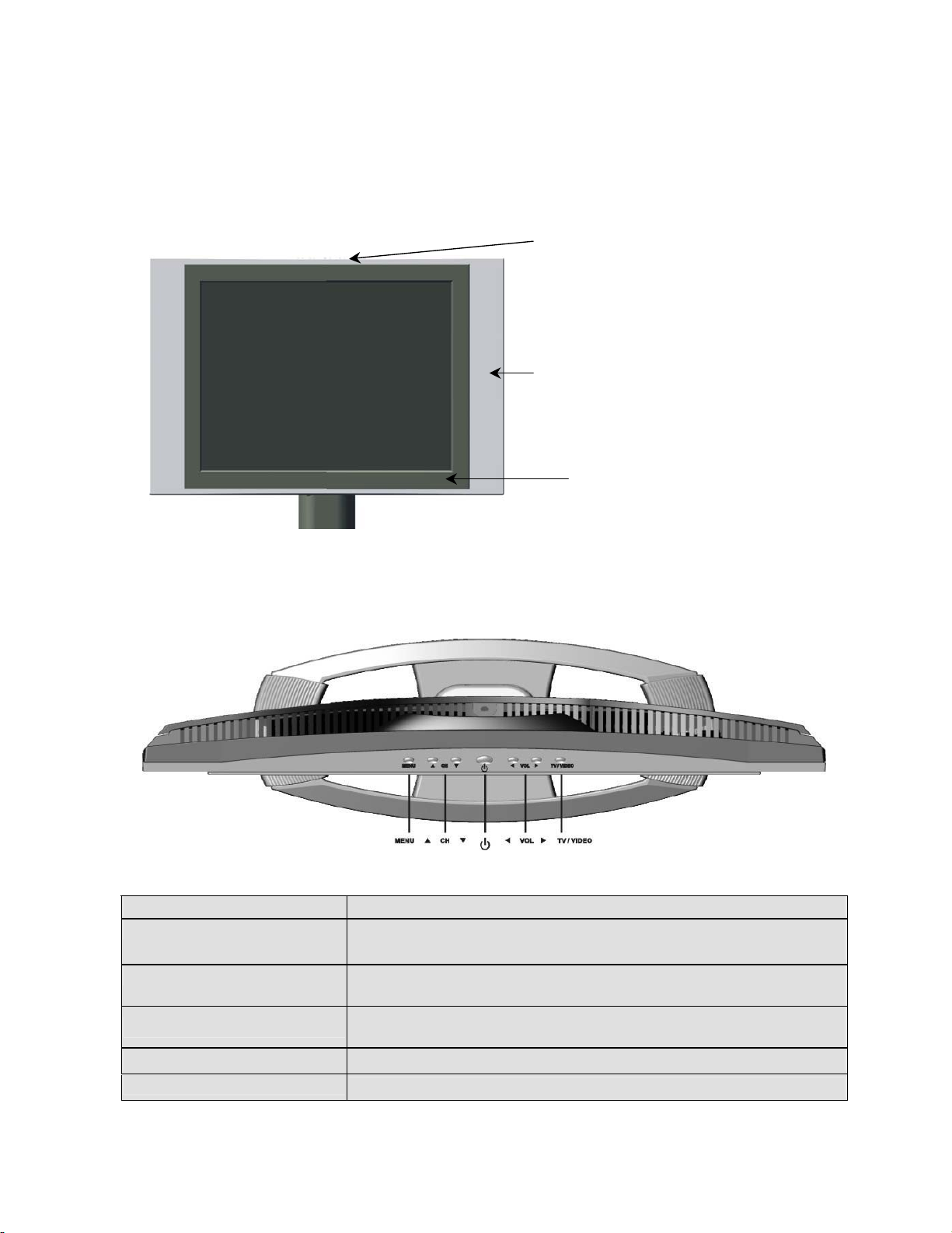
Front View of the Product
Use the buttons on the front panel control (or included remote control) to display and adjust
the On Screen Display (OSD). The OSD controls are explained at the top of the next page and
are defined in “OSD Functions” on page 11.
Top Control keys are shown in
detail below
Speaker
6. IR Receiver
Top Control keys
1 2 5 3 4
1 Menu Turn OSD Menu ON/OFF
2 Channel + / - Channel up/down when source is at TV or select a control while
in OSD Menu.
3 Volume + / - Increase/Decrease sound volume or adjust a highlighted control
while in OSD Menu.
4 TV/Video
5 Power Button Power ON/OFF
6 IR Receiver
Toggle the input source from RGB >> Component >> AV >>
S-Video >> TV
The Remote Control Receiver
5
Page 8
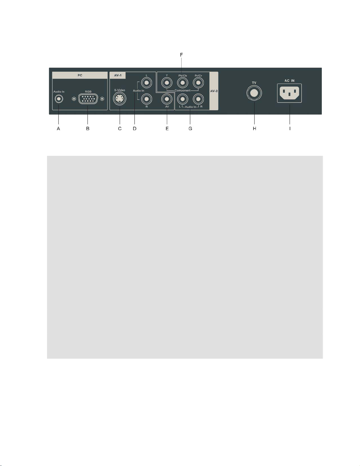
Rear View of the Product
PC
A. Audio In (PC)
Using cable provided connecting to the Audio out (Green) on your PC
B. RGB (VGA input)
Using the 15-pin VGA cable provided connecting to the RGB out on your PC
AV-1
C. S-Video input
Connect the S-Video to external video device such as VCR, DVD and Video game
. Audio input (Right / Left)
D
Connect the external audio to this jack; (Audio (R/L) inputs are supporting either
S-Video or AV input.)
. AV Video input
E
Connect the Composite Video (Yellow) to external video device such as VCR, DVD
and Video game
AV-2
. Component (Y Pb/Cb Pr/Cr) input
F
Connect the external video devices with component output to these jacks
G. Audio input (Right / Left)
Connect the external audio to this jack
TV
H. TV input
Connect to the antenna or cable service
AC IN
I. AC IN (Power)
Using cable provide connect to a power source
6
Page 9
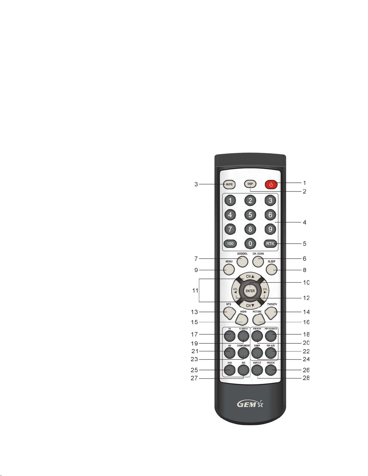
Remote Controls
The Remote Control is compatible with the display from up to 5m distances.
1. POWER:
Switch the power On/Off
2. DISP
Display the source and channel information
3. MUTE
Turn the Sound On/Off
4. CHANNEL NUMBER KEY
Set the channel
5. RTN
Recall the previous channel
6. CH.SCAN:
Auto scan all of the TV channels
7. ADD / DEL
To add or delete a TV channel
8. SLEEP
Set the TV sleep timer
MENU
9.
Press to display / exit the OSD
10. ENTER
Execute a command
11. CHANNEL Ÿ/ź
Channel Up/Down adjustmen; OSD menu
control
12.
VOLUME Ż/Ź
Volume Up/Down adjustment ; OSD menu
control
13. MTS
Multilanguage/Stereo selection
14. TV/CATV
Air/STD/HRC/IRC Selection
15. AUDIO
Adjust Audio function
16. PICTURE
Contrast/Brightness/Hue/Saturation
adjustment
17. TV
Source selected to TV mode
18. PIP SOURCE
Select PIP Sub picture source
19. S-VIDEO
Source selected to S-Video mode
20. PIP / POP
Display Main & Sub picture
21. AV
Source selected to AV mode
22. PIP SIZE
Adjust PIP Sub picture size
23. COMPONENT
Source selected to Component mode
24. SWAP
Switch PIP/POP Main/Sub source
25. VGA
Source selected to PC mode
26. FREEZE
Freeze the screen
27.DVI
No function for this model
28. ASPECT
Select Video display Aspect Ratio
7
Page 10
Installation
ʳ
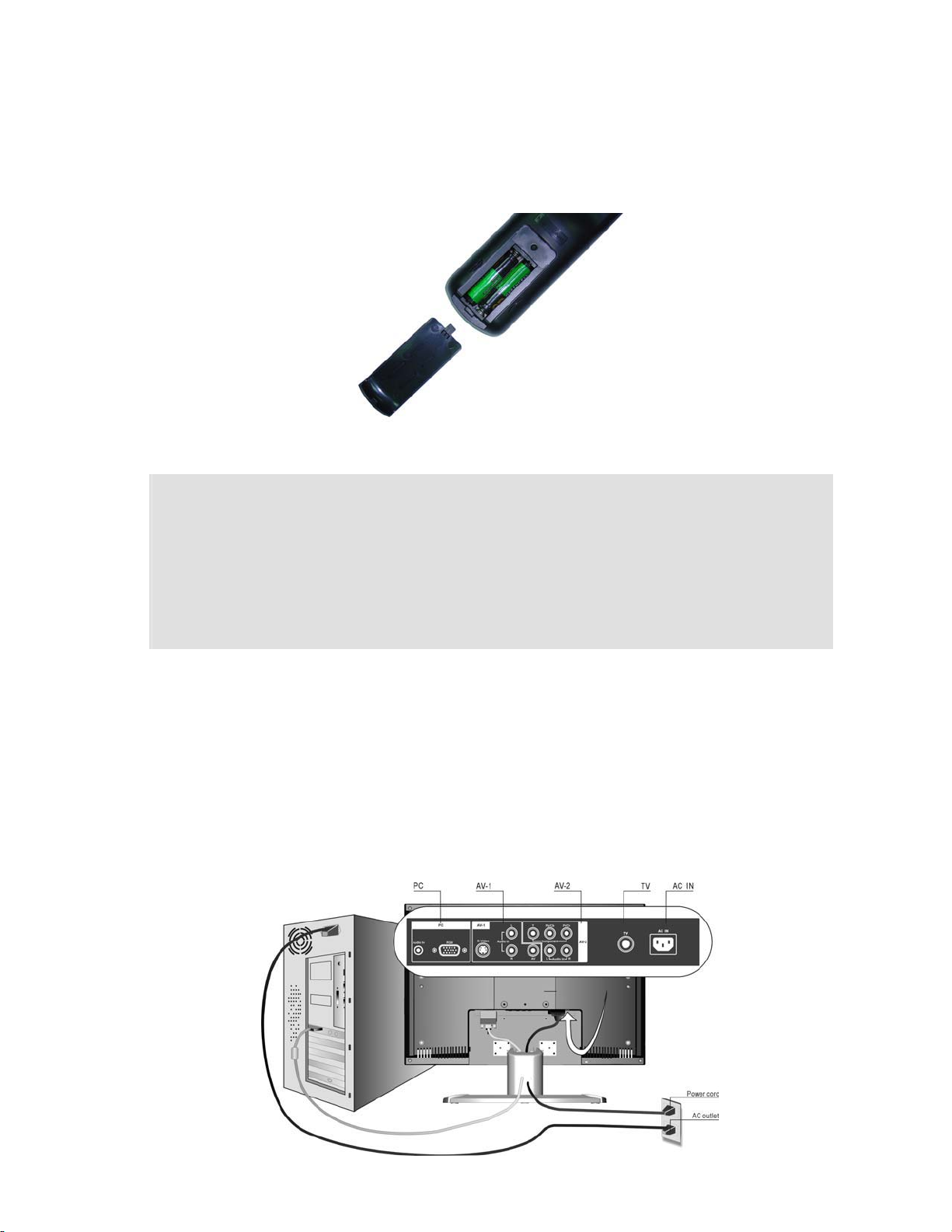
1. Insert Remote Control Batteries
1) Remove the battery cover.
2) Insert the batteries, corresponding to the (+) and (í) markings on the battery compartment.
3) Re-attach the battery cover.
CAUTION
x
Only use the specified AAA batteries.
x
Do not mix new and old batteries. This may result in cracking or leakage, which may pose a fire
risk or lead to personal injury.
x
Insert batteries according to (+) and (í) markings. Inserting the batteries incorrectly may result
in cracking or leakage, which may pose a fire risk or lead to personal injury.
x Dispose of the battery in accordance with local laws and regulations.
x Keep the battery away from children and pets.
xWhen the remote control will not to be used for an extended period, remove the batteries.
2. Connect audio and video cables to PC
Connect one or all of the following into the back of the LCDTV
IMPORTANT: Make sure all devices are off before you begin.
PC RGB CONNECTION: Connect the supplied analog VGA cable from your PC VGA OUT
port to the GLT20 LCDTV RGB IN port.
AUDIO CONNECTION: Connect the supplied stereo mini cable from the PC’s AUDIO OUT
port to the AUDIO IN port on the LCDTV.
8
Page 11

3. Connect AV, Y Pb/Cb Pr/Cr, S-Video, Antenna/Cable to Video Devices
Connect Video/Audio cables from compatible devices to the back panel of LCDTV.
9
Page 12
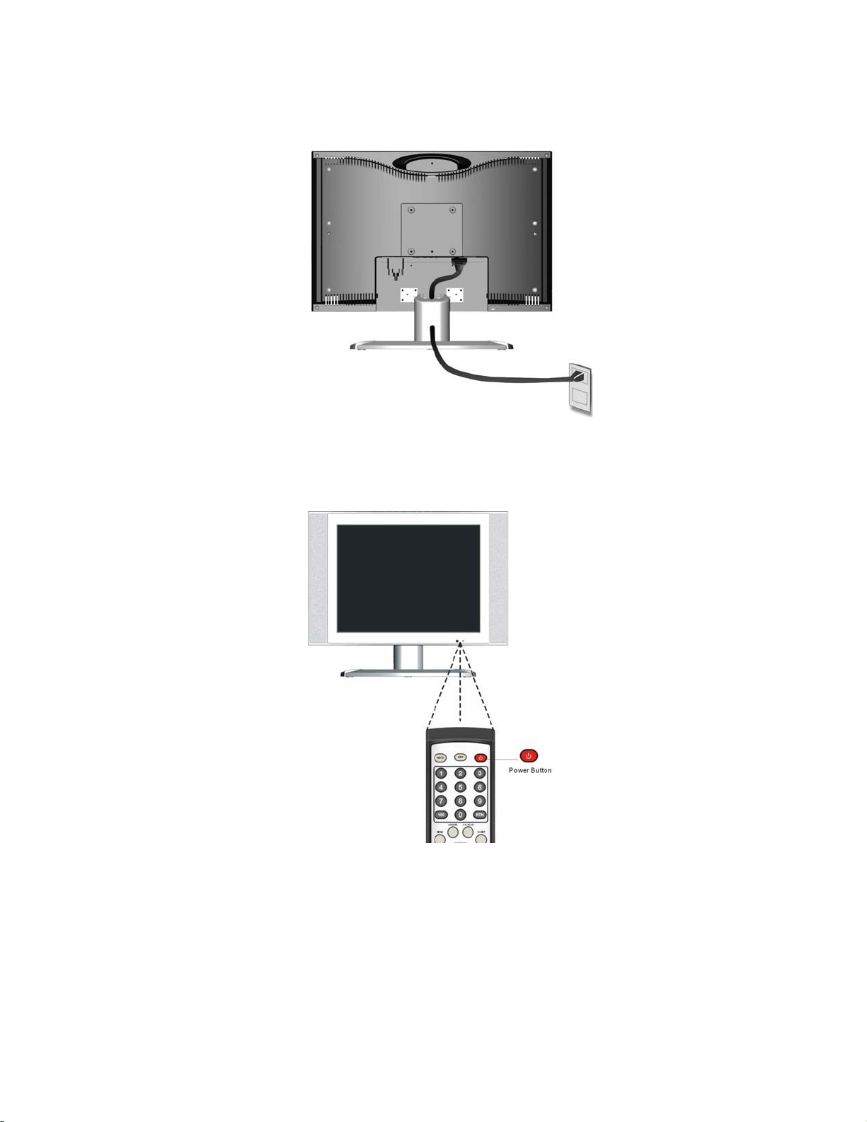
4. Connect power cables
Connect the power cord to the LCDTV then to a properly grounded AC outlet.
5. Turn Power On
Press the Power ON button on the top of the LCDTV display. Or press the Power On (Red)
button on the remote control.
6. Select input source for your LCDTV display, via either OSD menu or
remote control
1) For the best picture quality set your LCD display timing mode to VESA 640x480 at 60Hz,
refer to the graphic card’s user guide, for questions on how to set this timing mode.
10
Page 13
OSD Functions
All the function settings for your LCDTV display are controlled either via the remote
control or using the top control keys on the front panel.
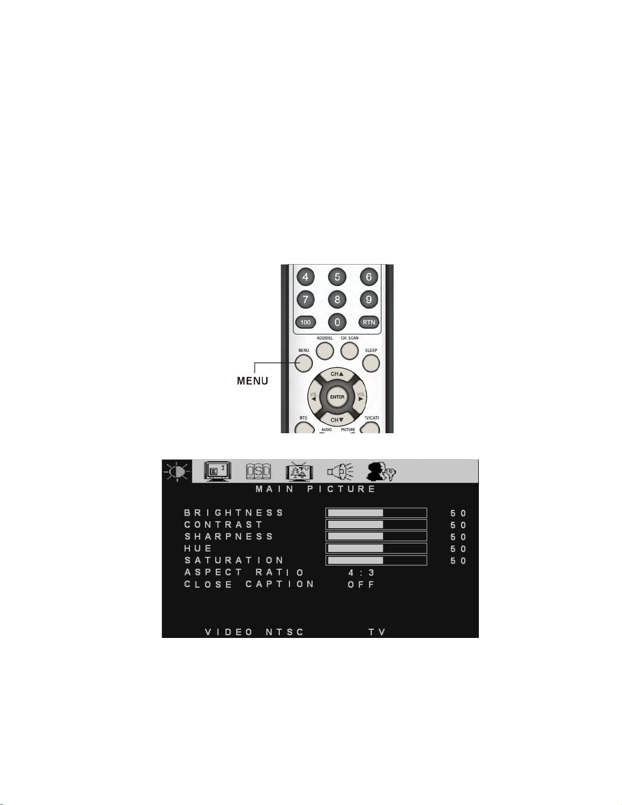
To display the OSD main menu, press Menu button on the front control keys or the
MENU/EXIT key on the remote control. Use Ż/Ź arrow keys to toggle the sub OSD menu
display (Main Picture >> Main Input >> Multi Screen >> OSD >> TV >> Audio >> Parental
Control). Use Ÿ/ź arrow keys to select the details of each sub OSD Menu, then use Ż/Ź
arrow keys to make the desired adjustment. Press OK Key to confirm the desired selection
and press Menu button or MENU/EXIT key again to exit the OSD Menu.
NOTE:
The OSD menu display will disappear automatically after 30 seconds, if no action is
taken.
11
Page 14

Source Input: TV or AV or S-Video
Main Picture Menu
Function Name Explanation
Brightness Adjust the Brightness of TV
Contrast Adjust the Contrast of TV
Sharpness Adjust the Video Sharpness
Hue Adjust the Video Hue level
Saturation Adjust the Video Saturation level
Aspect Ratio Select TV display on “4:3” / “16:9”
Close Caption Turn Closed Caption on / off select the type of desired. “OFF”, “CC1”,
“CC2”, “CC3”, “CC4”, “TT1”, “TT2”, “TT3”, “TT4”
Multi Screen Menu
Both PIP and POP functions are disabled.
Figure 1 Multi Screen
12
Page 15
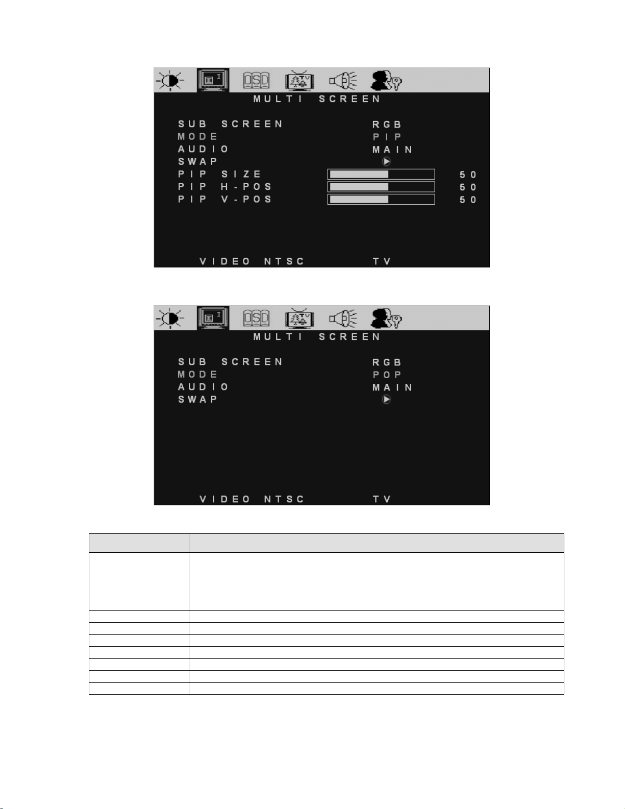
PIP function is enabled.
POP function is enabled.
Figure 2 PIP Menu
Figure 3 POP Menu
Function Name Explanation
SUB SCREEN Choose sub screen source,
ÖIf main screen (input) shown on either TV or AV or S-VIDEO, then sub screen
will has input selection on RGB or COMPONENT
Ö
If main screen (input) shown on either RGB or COMPONENT, then sub screen
will has input selection on TV or AV or S-VIDEO
MODE Select multi screen type: “OFF” / “PIP” / “POP”
AUDIO Select audio output source (Main or Sub)
SWAP Main screen and sub screen swap (Right key to execute)
PIP SIZE Adjust Sub screen size
PIP H-POS Adjust Sub screen Horizontal position
PIP V-POS Adjust Sub screen Vertical position
POP Display Side by Side Multi-Window
13
Page 16

OSD Menu
Function Name Explanation
H-POSITION Adjust OSD on horizontal position
V-POSITION Adjust OSD on vertical position
TRANSPARENCY Adjust OSD on transparency level
LANGUAGE Choose OSD language:
English, Spain, French, Traditional Chinese
DEFAULT Recall factory default setting. When this function is
executed, the screen will show the message
Figure 4. Default Message
14
Page 17

TV Menu
Function Name Explanation
MTS Selection included Stereo, Sap, Mono, Dual
INPUT SIGNAL TV Selection are either STD (standard cable), HRC (HRC cable), IRC (IRC
cable) or Air (Antenna)
AUTO SCAN Channel Auto scan (Right arrow key to execute)
SET CHANNEL Channel selection
CHANNEL ADD or Delete the selected Channel
SLEEP TIME(MINS) Set the sleep timer on TV from 00, 30, 60, 90, 120 minutes
Audio Menu
Function Name Explanation
VOLUME Adjust Volume level
BASS Adjust Bass level
TREBLE Adjust Treble level
BALANCE Adjust Left and Right speaker balance
15
Page 18

Parental Control Menu
Access the PARENTAL CONTROL menu the password must be key-in first (refer to Figure 5),
then press OK key to confirm selection. If the wrong password is entered, then refer to Figure 6.
Figure 5. Key-In Password Figure 6. Password Incorrect Warning
Password Edit Menu Figure 7. The warning message is displayed when
the wrong OLD Password
Function Name Explanation
PASSWORD EDIT Edit the password (Default is 0000)
OLD: _ _ _ _ Type the old password in 4 numbers, if the wrong password is entered,
then refer to Figure 7
NEW: _ _ _ _ Type the new password in 4 numbers
CONFIRM: _ _ _ _ Re-type the new password for confirmation
16
Page 19
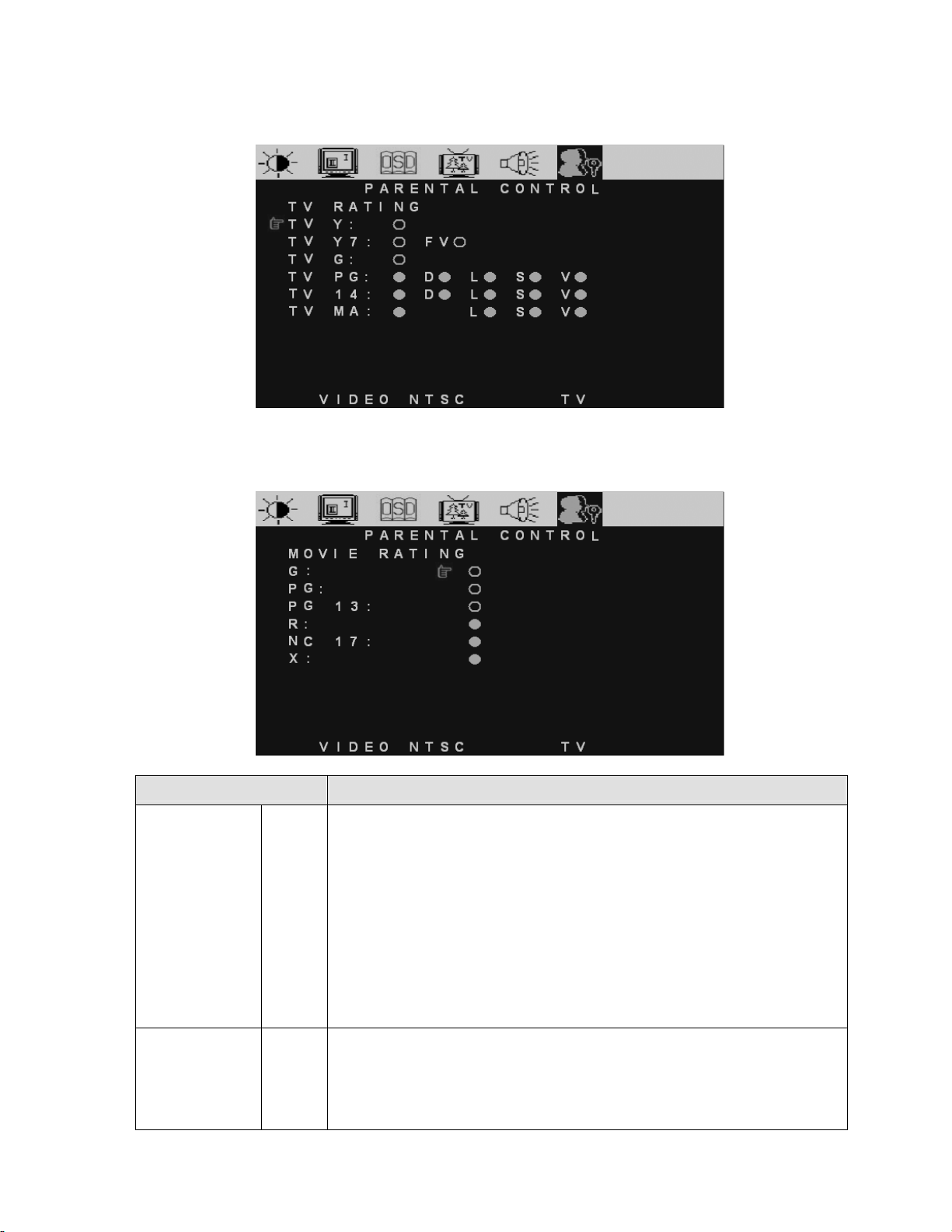
TV Rating Menu
Set the TV Ratings to block selected TV channels.
MOVIE Rating Menu
Set the Movie Ratings to block selected Movie channels.
Function Name Explanation
TV RATING
TV Y:
TV Y7:
TV G:
TV PG:
TV 14:
TV MA:
FV:
D:
L:
S:
V:
MOVIE RATING G:
PG:
PG 13:
R:
NC 17:
X:
<<< AGE >>>
All Children
Directed to Older Children
General Audience
Parental Guidance Suggested
Parents Strongly Cautioned
Mature Audience Only
<<< CONTENT >>>
Fantasy Violence
Suggestive Dialogue
Stronger Language
Sexual Situation
Violence
General audience
Parental Guidance suggested
Parents strongly cautioned
Restricted
No one 17 and under admitted
Adult audience only
17
Page 20

Source Input: Component
Main Picture Menu
Function Name Explanation
Brightness Brightness adjustment
Contrast Contrast adjustment
Sharpness Adjust the Video Sharpness
Hue Adjust the Video Hue level
Saturation Adjust the Video Saturation level
Aspect Ratio Select TV display on “4:3” / “16:9”
For the Main Input, Multi Screen, OSD, and Audio Menu operation, please refer to Pages
12~17.
18
Page 21

Source Input: PC
Main Picture Menu
Function Name Explanation
Brightness Brightness adjustment
Contrast Contrast adjustment
H-POSITION Adjust Horizontal Position on the image
V-POSITION Adjust Vertical Position on the image
FINE TUNE Adjust the Horizontal Phase on the image
H-SIZE Adjust the Horizontal size on the image
AUTO ADJUST Auto adjust the phase, clock, and position of the image.(Right key to execute)
COLOR ADJUST Color temperature adjustment: 9300k, 6500k, 5000k, and User color.
For the Main Input, Multi Screen, OSD, and Audio Menu operation, please refer to Pages
12~17.
19
Page 22

Other Information
ʳ
Specifications
Panel Type
Surface treatment Anti-reflective coating + Anti-glare coating
20.1" (full 20.1" viewable diagonal area), TFT (Thin Film Transistor),
Active Matrix VGA LCD, 640RGB*480 vertical stripe
Viewing angles
Input signal
Compatibility
Resolution
Speaker Output
Power Voltage 100-240 VAC, 50/60 Hz (auto switch), 1.5A
Video RGB Analog * 1 (75 ohms, 0.7 Vp-p)
Audio Mini-Stereo *1, RCA (L/R) Stereo * 2
PC Up to 1024 x 768 Non-interlaced
Macintosh1 Power Macintosh up to 1024 x 768
Supported 800 x 600 @ 60, 75, 85 Hz
Recommended 640 x 480 @ 60, 75, 85 Hz
5W * 2
160° (H) / 140° (V)
H/V separated (TTL) for PC
f
h:30-69 kHz, fv:50-85 Hz
TV system antenna / NSTC in US and TW
Composite Video * 1
S–Video * 1
Component Video * 1 ( YCbCr, YPbPr)
640 x 480 @ 60, 75, 85 Hz
720 x 400 @ 70 Hz
Operating conditions Temperature 32° F to + 95° F (0° C to + 35° C)
Humidity 20% to 90% (no condensation)
Altitude To 3,000 Meter
Storage conditions
Dimensions Physical 573 mm (W) x 472 mm (H) x 227.5mm (D)
Weight
Regulations
Power saving On <73W (Blue LED)
modes Active Off <5W (LED OFF)
Preset Timing Mode (Pre-adjusted to VESA 640x480 at 60Hz)
Warning:
Note: Product Specifications are subject to change without notice.
Do not set the graphics card in your computer to exceed these refresh rates; doing so may result in
permanent damage to the LCD display.
Temperature -4° F to + 140° F (-20° C to + 60° C)
Humidity 5% to 90% (no condensation)
Altitude To 12,000 Meter
22.76" (W) x 18.58” (H) x 8.96” (D)
Net 19.8lb (9.0 kg)
FCC-B, UL, c-UL,
20
Page 23

Troubleshooting
No power
x Make sure DC power button is ON (Green LED)
x ҏҏMake sure AC power cord is securely connected to the AC socket
x Plug another electrical device (like a radio) to the power outlet to verify that the outlet is
supplying the proper voltage
Power is ON but no screen image
x Make sure the video cable supplied with the LCD display is tightly secured to the video
output port on the back of the computer. If the other end of the video cable is not
attached permanently to the LCD display, tightly secure it to the LCD display
ҏҏAdjust brightness and contrast
x
x If you are using a Macintosh older than G3, you need a Macintosh adapter
x Check Source settings
Wrong or abnormal colors
x If any colors (red, green, or blue) are missing, check the video cable to make sure it is
securely connected. Loose or broken pins in the cable connector could cause an
improper connection
x Connect the LCD display to another computer
Control buttons do not work
x Press only one button at one time
Snow appears on screen
x Check your antenna connection
x Check TV / CATV selection
No sound
Check your audio connection
x
x Press MUTE on the remote control again, so that MUTE disappears from the screen
x Check your audio settings, your TV audio may be set to SAP or minimum
x Press the Volume + (Up) key on your remote control
Make sure that headphones are not connected
Remote Control does not work
x Make sure batteries are inserted correctly
Batteries could be weak
x
21
Page 24

Cleaning the Display
Make sure the product is turned off before cleaning
x
x Never spray or pour any liquid directly onto the product. Spray a clean cloth and wipe the
product clean
x Never immerse the product in any liquid
To clean the screen:
1. Wipe the screen with a clean, soft, lint-free cloth. This removes dust and other particles.
2. If still not clean, apply a small amount of non-ammonia
onto a clean, soft, lint-free cloth, and wipe the screen.
To clean the case:
1. Use a soft, dry cloth.
2. If still not clean, apply a small amount of non-ammonia, non-alcohol based, mild
non-abrasive detergent onto a clean, soft, lint-free cloth, then wipe the surface.
Disclaimer
GEM does not recommend the use of any ammonia or alcohol-based cleaners on the product.
Some chemical cleaners have been reported to damage the screen and/or the display case.
GEMS will not be liable for damage resulting from use of any ammonia or alcohol-based
cleaners.
, non-alcohol based glass cleaner
22
Page 25
Appendix
ʳ
Safety Guidelines
Warning:
This device must be operated with the original power supply, part number: ADP-60CF A.
CAUTION: The socket-outlet should be installed near the equipment and should be easily accessible.
CAUTION: Use a power cable that is properly grounded. Always use the appropriate AC cord that is certified for
the individual country. Some examples are listed below:
USA.................UL Switzerland ..... SEV
Canada.............CSA Britain ............. BASE/BS
Germany..........VDE Japan ............... Electric Appliance Control Act
IMPORTANT NOTICE CONCERNING POWER CORD SELECTION
The power cord set for this unit has been enclosed and has been selected according to the country of destination
and must be used to prevent electric shock. Use the following guidelines if it is necessary to replace the original
cord set, or if the cord set is not enclosed.
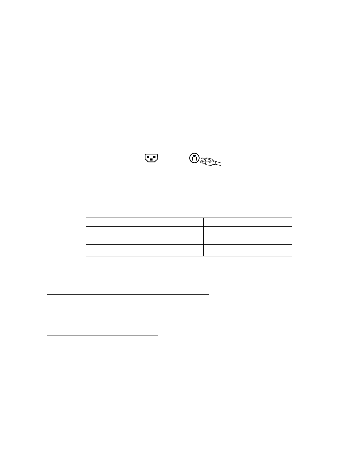
The female receptacle of the cord set must meet IEC-60320 requirements and may look like (Figure A1 below):
Figure A1 Figure A2
For the United States and Canada
In the United States and Canada the male plug is a NEMA5-15 style (Figure A2), UL Listed, and CSA Labeled.
For units which are mounted on a desk or table, type SVT or SJT cord sets may be used. For units which sit on
the floor, only SJT type cord sets may be used. The cord set must be selected according to the current rating for
your unit. Please consult the table below for the selection criteria for power cords used in the United States and
Canada.
Cord Type Size of Conductors in Cord Maximum Current Rating of Unit
SJT 18 AWG
16 AWG
14 AWG
SVT 18 AWG
17 AWG
10 Amps
12 Amps
12 Amps
10 Amps
12 Amps
For European Countries
In Europe you must use a cord set which is appropriate for the receptacles in your country. The cord set is HARCertified, and a
special mark that will appear on the outer sheath, or on the insulation of one of the inner conductors.
AC PLUG CORD PRECAUTIONS FOR THE UNITED KINGDOM
FOR YOUR SAFETY PLEASE READ THE FOLLOWING TEXT CAREFULLY.
IF THE FITTED MOULDED PLUG IS UNSUITABLE FOR THE SOCKET OUTLET THEN THE PLUG SHOULD BE CUT OFF
AND DISPOSED OF SAFELY.
THERE IS A DANGER OF SEVERE ELECTRICAL SHOCK IF THE CUT OFF PLUG IS INSERTED INTO AN APPROPRIATE
SOCKET.
If a new plug is to be fitted, please observe the wiring code as shown below.
If in any doubt, please consult a qualified electrician.
WARNING:
IMPORTANT: The wires in this mains lead are coloured in accordance with the following code:
If the coloured wires of the mains lead of this appliance do not correspond with the coloured markings identifying the terminals in
your plug, proceed as follows:
The wire which is coloured GREEN-AND-YELLOW must be connected to the terminal in the plug which is marked by the letter E
or by the Earth symbol or coloured GREEN or GREEN-AND-YELLOW.
The wire which is coloured BLUE must be connected to the terminal in the plug which is marked with the letter N or coloured
BLACK. The wire which is coloured BROWN must be connected to the terminal in the plug which is marked with the letter L or
coloured RED.
If you have any questions concerning which proper power cord to use, please consult with the dealer from whom you have
purchased the product.
THIS APPLIANCE MUST BE EARTHED.
Green-and-Yellow: Earth
Blue: Neutral
Brown: Live
23
Page 26

Compliance Information for U.S.A.
This equipment has been tested and found to comply with the limits for a Class B digital device, pursuant to part 15 of the FCC Rules.
These limits are designed to provide reasonable protection against harmful interference in a residential installation. This equipment
generates, uses, and can radiate radio frequency energy, and if not installed and used in accordance with the instructions, may
cause harmful interference to radio communications. However, there is no guarantee that interference will not occur in a particular
installation. If this equipment does cause harmful interference to radio or television reception, which can be determined by turning the
equipment off and on, the user is encouraged to try to correct the interference by one or more of the following measures:
• Reorient or relocate the receiving antenna.
• Increase the separation between the equipment and receiver.
• Connect the equipment into an outlet on a circuit different from that to which the receiver is connected.
• Consult the dealer or an experienced radio/TV technician for help.
FCC Warning
To assure continued FCC compliance, the user must use grounded power supply cord and the provided shielded
video interface cable with bonded ferrite cores. If a BNC cable is going to be used, use only a shielded BNC (5)
cable. Also, any unauthorized changes or modifications not expressly approved by the party responsible for
compliance could void the user's authority to operate this device.
24
 Loading...