

SDEC1000A & SDEC2500A Flash Chip Exchange Instructions
To: JBL SIS Dealers & Reps
From: Chris Neumann
Subject: Transferring SDEC settings by swapping Flash IC’s
Date: 6/18/02
When replacing an SDEC Digital Equalizer, as an alternative to using the Loader
utility, the flash memory chips on the DSP Engine inside the SDEC, which contain the
programmed filter, delay and crossover settings may be swapped. With SDEC1000/A
swapping flash chips is a more reliable method of transferring files to a replacement
unit. Follow the procedure below to swap SDEC.d97 file settings.
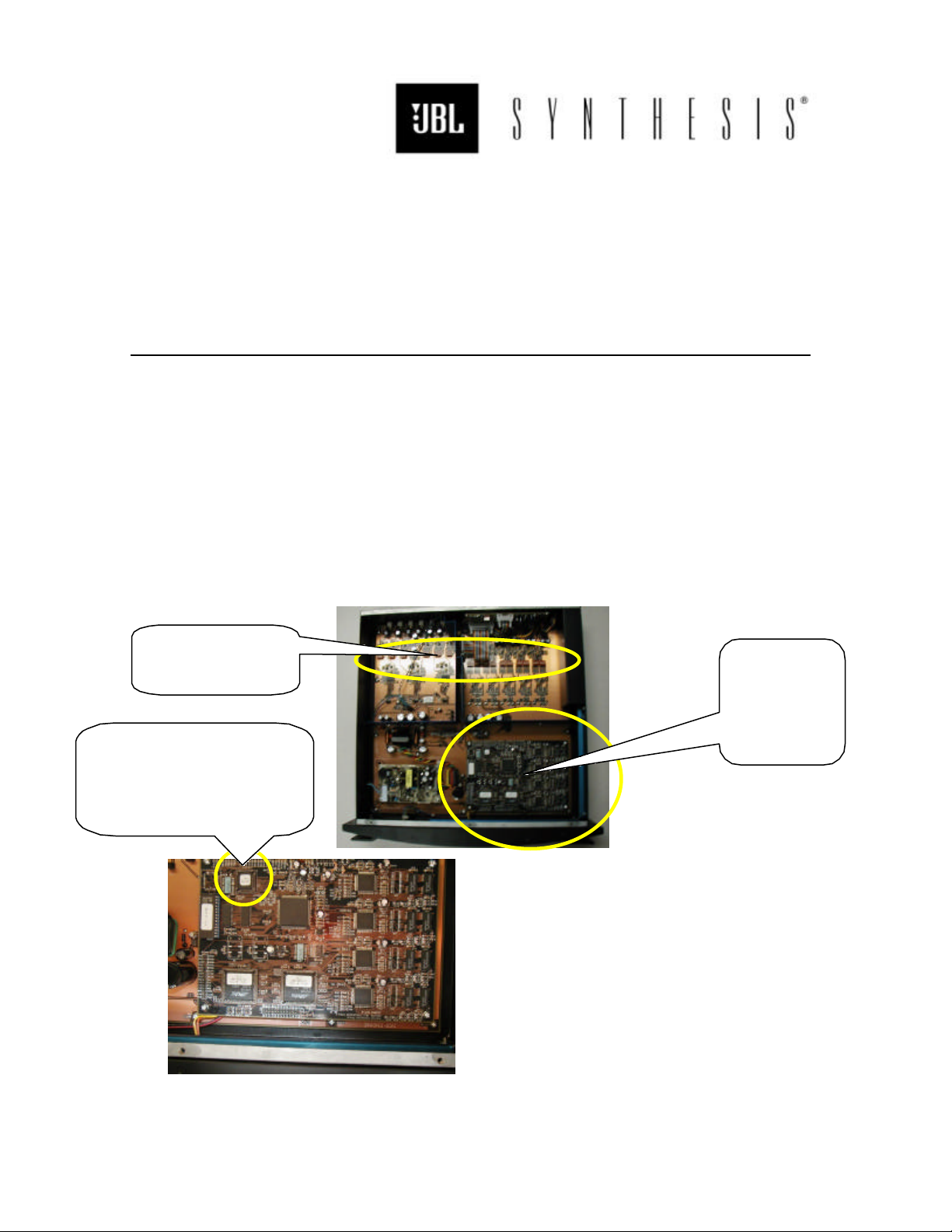
1. Remove the malfunctioning SDEC from the equipment rack.
2. Remove the SDEC top cover.
Headroom DIP
Switches
U3 on DSP Engine
1V6 for SDEC1000/A
2V6 for SDEC2500/A
3. Locate U3 on the DSP Engine Board (see Fig.2).
DSP
Engine
Board
Fig. 1
Fig. 2
SDEC1000A & SDEC2500A Flash Chip Exchange Instructions Continued
6/18/02 Page 2
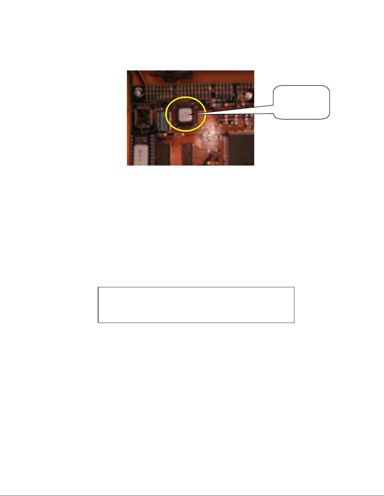
Flash Chip
@ U3
Fig. 3
4. Carefully remove the flash chip at designator U3 on the DSP Engine Board
with a PLCC IC puller or a small screwdriver or paperclip (see Fig.3). Be careful
not to damage any of the pins on the chip or the IC socket, as this will cause
the unit not to function properly.
5. Repeat steps 2, 3, & 4 with the replacement unit and swap the Flash chips. Be
sure to reinstall the chips correctly into the keyed sockets.
6. Copy over the Headroom DIP Switch settings for input sensitivity and output
gain from the malfunctioning unit to the replacement unit to ensure proper
headroom settings for the system (see Fig.1).
DIP Switch Factory Default settings = Unity Gain
Inputs: L, C, R = “-3dB”, L/R Ambient & Sub = “0dB”
Outputs L, C, R = “+3dB”, L/R Ambient & Sub = “0dB”
7. Copy over the rear panel switch settings for Auto/Manual turn-on and
Cinema/Auto switching modes.
8. Reattach the top cover of the replacement unit and reinstall it into the system.
Your system should now function normally with the appropriate filter, delay,
and crossover settings.
9. Reattach the top cover of the malfunctioning unit, box the unit in the original
or replacement’s packing, and return to JBL using the supplied RA number to
make sure your account receives credit against the replacement.
JBL Systems Integration Specialist Products Group
Northridge, CA 91329 Ph: 818.895.5712 Fax: 818.920.3609 e-mail: cneumann@harman.com
 Loading...