

Page 1

UP Mini 3D Printer User Manual 1
Page 2

UP Mini 3D Printer User Manual 2
Legal Notice
The information in this document is subject to change without notice.
3D PRINTING SYSTEMS LTD. MAKES NO WARRANTY OF ANY KIND WITH
REGARD TO THIS MATERIAL, INCLUDING, BUT NOT LIMITED TO, THE
IMPLIED WARRANTIES OF MERCHANTABILITY AND FITNESS FOR A
PARTICULAR PURPOSE. 3D Printing Systems Limited shall not be liable for
errors contained herein or for incidental or consequential damages in
connection with the furnishing, performance, or use of this Material. Changes
or modifications to the system not expressly approved by 3D Printing Systems
Ltd., the party responsible for compliance, could void the user’s authority for
use. This document is protected by copyright. All rights reserved. Its use,
disclosure, and possession are restricted by an agreement with 3D Printing
Systems Ltd. per software copyright. No part of this document may be
photocopied, reproduced or translated into another language without the prior
written consent of 3D Printing Systems Ltd.
© Copyright 2012 3D Printing Systems Limited. All rights reserved.
Page 3

1. Introduction
UP Mini 3D Printer User Manual 3
1. INTRODUCTION ................................................................................................................... 4
1.1 H
OW TO USE THIS MANUAL
.................................................................................................. 4
1.2 P
RECAUTIONS
.................................................................................................................... 4
1.2.1 Safety ........................................................................................................................ 4
1.2.2 Protection .................................................................................................................. 5
2. OVERVIEW ........................................................................................................................... 6
2.1 A
PPEARANCE
..................................................................................................................... 6
2.2 S
PECIFICATIONS
................................................................................................................. 9
2.2.1 Printer Physical Characteristics ................................................................................ 9
2.2.2 Specifications ............................................................................................................ 9
2.2.3 Environmental specifications .................................................................................... 9
3. OPERATION ........................................................................................................................ 10
3.1 P
REPARATION
.................................................................................................................. 10
3.1.1 Installing the printer ................................................................................................. 10
3.1.2 Installing the software ............................................................................................. 12
3.1.3 Installing drivers ...................................................................................................... 12
3.2 U
SING THE BASIC FUNCTIONS
............................................................................................ 18
3.2.1 Start the program .................................................................................................... 18
3.2.2 Loading a 3D model ................................................................................................ 18
3.2.3 View Options ........................................................................................................... 21
3.2.4 Model transformations ............................................................................................ 23
3.2.5 Placing models onto the build platform ................................................................... 25
3.3 G
ETTING READY TO PRINT
................................................ E
RROR! BOOKMARK NOT DEFINED
.
3.3.1 Initializing the Printer ............................................................................................... 14
3.3.2 Calibrating the Nozzle Height ................................................................................. 15
3.3.3 Leveling the print platform ......................................... Error! Bookmark not defined.
3.3.4 Other Maintenance Options .................................................................................... 26
3.3.5 Preparing the Platform ............................................................................................ 28
3.3.6 Print Setup Options ................................................................................................. 29
4. PRINTING ............................................................................................................................ 34
5. MODEL REMOVAL ............................................................................................................. 36
R
EMOVING SUPPORT MATERIAL
.............................................................................................. 38
6. MAINTENANCE .................................................................................................................. 40
C
HANGING THE MATERIAL
....................................................................................................... 40
V
ERTICAL CALIBRATION
.......................................................................................................... 40
C
LEANING THE NOZZLE
........................................................................................................... 42
R
EMOVING / CHANGING THE NOZZLE
....................................................................................... 43
C
LEANING THE PLATFORM
....................................................................................................... 43
L
UBRICATION OF BEARINGS
..................................................................................................... 43
S
PARE PARTS
......................................................................................................................... 43
7.0. TIPS & TRICKS ................................................................................................................ 45
8. TROUBLESHOOTING ........................................................................................................ 46
S
OLUTION FOR
"USB.
DLL NOT FOUND" PROBLEM
..................................................................... 46
Page 4

1. Introduction
UP Mini 3D Printer User Manual 4
1. Introduction
1.1 How to use this manual
This User Manual is divided into four sections which cover the Introduction,
Overview, Operation, and Troubleshooting. Please study this manual carefully
before installation, and use the printer according to these instructions. Keep
this manual handy and refer to it when necessary.
1.2 Precautions
Please read this section carefully before using the printer.
1.2.1 Safety
The printer can only be used with the power adapters supplied by this
company, or the product may be damaged, with a risk of fire.
To avoid burning, or model deformation, do not touch the model, nozzle, or
the platform by hand, or any other part of the body, while the printer is
working or immediately after it has finished printing.
Protective glasses should always be worn when removing support material,
especially PLA.
The brown sections of the currently supplied gloves melt at around 200
degrees, therefore please do not hold the extruder block with the gloves.
There is a slight smell from ABS when it is being extruded. The smell is,
however, not too unpleasant. Operate in a well ventilated room but draught
free. Draughts can affect warping of ABS prints. When ABS is burnt is
releases toxic fumes.
Do not use ABS plastic or its printed parts near any kind of heat source,
flames, fireworks, candles, incense, light bulbs etc. ABS will catch fire and
burn a thick black smoke.
Always have adult supervision when children are present. Please keep all
small printed parts away from young children, choking hazards! There are
several safety issues, small tools, sharp tools and HOT objects and most
parts used in connection with the 3D Printer. Tie back long hair and loose
clothing. Keep fingers away from moving parts.
Tools and parts should be stored at a suitable height.
Tools should be used in conjunction with safety gloves.
Page 5

1. Introduction
UP Mini 3D Printer User Manual 5
The following classifications are used in this manual.
CAUTION: Indicates a potentially hazardous situation which, if not
avoided, may result in minor or moderate injury.
WARNING: Indicates a potentially hazardous situation which, if not
avoided, may result in serious injury.
Gloves: When performing certain maintenance procedures, the
machine may be hot and gloves are required to avoid burns.
Safety Glasses: Wear safety glasses to avoid injury to your eyes.
1.2.2 Protection
The printer must not be exposed to water or rain, or damage may occur.
Do not shut down the UP! System or pull out the USB cable when loading
a digital model, or the model data may be lost.
When using the “Extrude” function, keep at least 50mm between the
nozzle and the platform. If too close, the nozzle may get blocked.
The printer is designed to work properly at an ambient temperature of
between 15°C and 30°C and humidity of between 20% and 50%;
Operating outside these limits may result in low quality models.
Page 6

UP Mini
3D Printer User Manual
2. Overview
The UP Mini 3D Printer
mind. The system
and software
keystrokes
, even if you h
a nozzle to
deposit molten plastic, so print
Congratulations
on purchasing an
2.1 Appearance
Figure 1
2. Overview
is designed with ultimate portability and simplicity in
allow you to print great models with only a few
ave never used a 3D printer before. The system
ed parts are strong and durable.
UP Mini 3D Printer.
. Front view of printer
6
uses
Page 7

UP Mini
3D Printer User Manual
Figure
2. Overview
2. Back view of printer
7
Page 8

UP Mini
3D Printer User Manual
①①①①
USB cable
④④④④
Spare screws
1)
Pen Knives
⑤⑤⑤⑤
Cutters
2. Overview
Figure 2. Accessories
②②②②
Power adapter (20 V)
③③③③
Filament tube
⑤⑤⑤⑤
Perfboard
Figure 3. Tool kit
②②②②
Tweezers
③③③③
Hex wrench
④④④④
⑥⑥⑥⑥
Gloves
⑦⑦⑦⑦
Nozzle wrench
Figure 4. Axis
8
④
Spatula
⑧⑧⑧⑧
Clips
Page 9

UP Mini
3D Printer User Manual
2.2 Specifi
cations
2.2.1 Printer
Physical Characteristics
Printing
Material
Material
Color
Layer Thickness
Print Speed
Print Bed
Size
Printer
Weight
Printer Size
2.2.2
Specifications
Power Requirements
Model
Support
Input
Format
Workstation
compatibility
2.2.3 Environmental
Ambient temperature
Relative humidity
2. Overview
ABS or PLA
White
0.25-0.35mm
10-100 cm3/h
120×120×120mm
5 KG (11 lb)
245 × 350 × 360 mm
100-240VAC, 50-60Hz,
200W
Smart auto-generated
and
easy to break away s
upport
material.
STL
Windows XP/Vista/7; Mac
specifications
15°C~30°C
20%~50%
9
Page 10

UP Mini
3D Printer User Manual
3. Operation
3.1 Preparation
3.1.1 Installation
of
Remove c pieces of
pack
Mount the
roll holder
Clip on the
roll holder onto the back of the printer.
3.
Operation
the printer
ing foam, one on the inside back wall,
Operation
10
Page 11

UP Mini
3D Printer User Manual
Mount the Extruder Head
Clip in the Extruder head, with its magnetic
clip system. The fan goes on the left h
side. Then plug in the ribbon cable connector.
The extuder has a LED lighting to light the model
dur
ing printing. Double tap the front intilise button to
switch on or off the
internal lighting.
Load the Roll of filament
1.
Open the foil bag that
2. Load the Spool
onto the spool holder, ensuring the
filament unwinds
as per
3.
Feed the end of the filament between the roll
guide.
4.
Feed the filament into the feeder tube and feed about 10cm out the other end of the feeder
tube.
5.
Feed the filament and tube inside the
6.
Insert the end of the ABS filament into the printer head.
Connect the Printer
1.)
Connect the USB cable between the Computer and the Printer
hand side).
2.)
Connect the power supply to th
hand side
of the printer, plug the power supply to the mains outlet.
3.) Visit
www.3DPrintingSystems.com/support
software for MAC and Windows
software install procedure in 3.1.2
4.)
Power on the printer on at the back.
Slide the Perfboard
into
binder clips in order to hold the Perfboard onto the platform.
remove the Perfboard t
o remove printed models from the printer.
3.
Operation
and
contains the filament.
above diagram.
filament
back of the top door.
e “Power interface” located
to download the latest
and install the software.
(
)
the platform (between the groves)
and attach the
Warning:
Do not let go of the
otherwise it will unravel
itself and tie itself in a knot, which
will then cause a block in t he extruder head and several hours
of unwinding the spool manually to find the knot!
Operation
11
(left
on the left
refer to the
TIP: Always
end o f t he filament,
Page 12

UP Mini
3D Printer User Manual
3.1.2 Installing the software
Visit
www.3DPrintingSystems.com/support
MAC and Windows and install the software.
Windows:
Start the UPx.xx setup.exe file and install it to the specified directory
(Default is Program files/UP). Note: This installs the UP software, the UP
drivers, and the UP sample files into your Program files/UP folder.
3.1.3 Installing drivers
Connect th
e printer to a computer with the USB cable. The computer should pop
up the “Found New Hardware Wizard” window. Choose “No, not this time”, and
then “next”. Then c
hoose “Install from a list or specific location (Advanced)”,
then “Next”.
3.
Operation
to download the latest software for
Operation
12
Page 13

UP Mini
3D Printer User Manual
Click “Browse”,
and choose C:
The following dialogue box pops up. Choose “Continue Anyway”, and the
drivers will install automatically.
If you have any problems i
error
, please refer to the driver section in the troubleshooting section of this
manual.
3.
Operation
\Program Files\UP\
Driver, then “Next”.
nstalling the drivers, or get a
"Winusb.dll not found"
Operation
13
Page 14

UP Mini
3D Printer User Manual
3.3.1 Initializing the Printer
Before anything can be printed, the printer must be initialized. Click the
“Initialize” option under the “3D print” menu. The printer will b
initialization procedure will begin. The printer will then return the platform and
print head to the printer’s origin and beep again when it is ready.
TIP: If your printer is not responding properly, the
re-
initialize the printer by clicking the ‘Initialize’ option from the ‘3D
Print’ menu.
If still not working switch off and on the printer at the
back. Check the trouble shooting section.
The printer can also be initialized by pres
3.
Operation
(Windows version)
(Mac version)
first thing to try is to
sing the front switch on the printer.
Operation
14
eep and the
Page 15

UP Mini
3D Printer User Manual
3.3.2 Setting
the
This section is probably the most important of the entire manual. Please
read it carefully to ensure that you understand the
procedure, as it is vital to success
To print successfully, the platform should be set to start at a distance of 0.2mm
(Business card thickness)
this distance needs to be calibrated before starting to print.
distance between the nozzle and platform is recorded in the “Nozzle” box
of the “Print
” screen (found under the “3D Print” menu, but we use the
“Maintain” dialogue box to figure out what this distance should be.
NOTE:
It is only possible to move the nozz
recorded in the “Print” screen. If, for example, the nozzle height in the
“Print” screen is set to 1
up to 11
8mm in the “Maintenance” screen. This maximum value is
indicated by
the “Max” value shown in the platform and nozzle line of the
“Maintain” screen.
table into the nozzle and causing extensive damage.
If you are having problems adjusting the nozzle height in the
“Maintenanc
e “ screen because it will not go high enough, close the
“Maintenance” screen, open the “Print” screen,
height to 122
mm (for example). Then go back to the “Maintenance”
screen and continue with your nozzle height adjustments.
In the a
bove example, this tells the printer that, after being initialized, and
when a print job begins, the platform is 139.5mm away from the nozzle.
To work
out the correct nozzle distance,
please follow these steps:
1 -
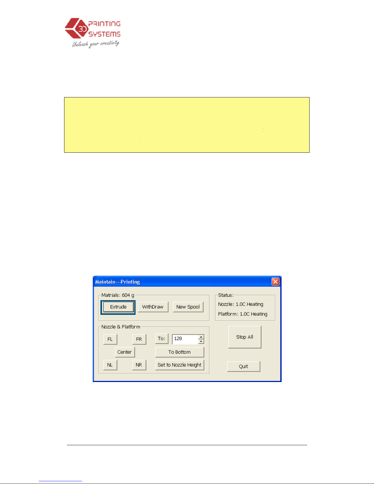
Open the “Maintain” dialogue box from
t
he “3D Print” menu. The current nozzle
height is indicated as s
picture below.
3.
Operation
Platform Height
platform
ful 3D printing.
from the nozzle. As each printer is slightly different,
le to 8mm higher than the height
1
0mm, you will only be able to move the nozzle
This is a safety measurement to avoid crashing the
and set the nozzle
hown in the
(Windows version)
Operation
15
height setup
The correct
Page 16

UP Mini
3D Printer User Manual
2 -
In the text box, type in the height to which you want the platform to move to,
and click the “To” button. In the above examp
119.2
mm above the platform’s origin.
3 -
Check the distance between the nozzle and the platform. If, for example,
the platform appears to be about 7mm away from the nozzle, increase the
number in the text box to 1
only increased the number by 3mm instead of 4mm. The reason for this is
that we do not want to crash the platform into the nozzle, so we want to
increase the height in smaller and smaller increments as we get closer to
the nozzle.
4 -
Once you are about 1mm away from the nozzle, start increasing the
number in the text box by 0.1mm increments and click the “To” button.
Repeat this until you get to within 0.2mm of the nozzle.
TIP:
An easy way to check the distance betwe
fold a piece of paper in two (Which will make it about 0.2mm thick) and
use that as a spacer to gauge the distance between the nozzle and
platform.
5 -
Once you are within 0.2mm of the nozzle, write down the number you h
in the “To” box. This is the correct calibration height! Close the “Maintain”
window and open the “Setup” Window. In the “Setup” window “Nozzle” box,
enter the number you recorded on the “Maintain” Screen. Alternatively, you
can click the “Set to Nozzl
value across to the setup screen. You have now successfully setup the
nozzle height.
6 –
Now click “Goto Bottom” in the Maintenance screen.
NOTE: Once you have setup the nozzle height once, you do not need to
do it again as it is automatically recorded in the “Setup” Screen.
3.
Operation
le
, the platform would m
20 and click
the “To” button. Note that we have
en the nozzle and platform is to
e Height” button to automatically transfer the
Operation
16
ove to
ave
Page 17
UP Mini
3D Printer User Manual
TIP:
You may need to regularly recalibrate nozzle height after moving the
printer, or if you find the models are not adhering to the platform properly,
or are warping.
TIP: If you hap
pen to crash the platform into the nozzle while
adjustment,
always
operations and start again.
Loading the filament into the Extruder Head
1.)
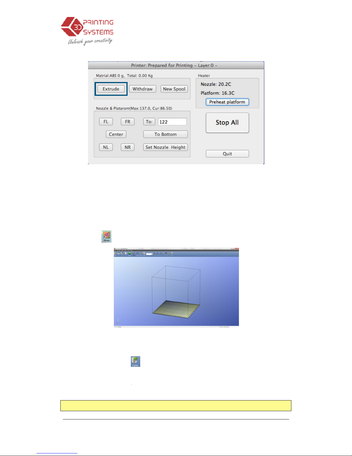
Click on the menu “
printer extruder will now start to heat
2.)
After the printer nozzle has warmed up to 260°C, the printer will beep.
Push the filament into the hole at the top of the extruder head and
the filament in wi
it and starts pulling it through the extrusion head. The extruder will then
automatically extrude a thin filament of material.
a second time (meaning the extrusion process is co
the piece of extruded plastic.
3.
Operation
setting the
re-
initialize the printer before undertaking any
3DPrint” -> “Maintenance” -> “
Extrude
. (
Takes approximately 10mins)
th some gentle pressure until the extruder motor grabs
After the printer beeps
mplete), pull away
(Windows version)
Operation
17
height
further
”. The
push
Page 18
UP Mini
3D Printer User Manual
3.2 Using the basic functions
3.2.1 Start the program
Click on the
icon on the desk
3.2.2 Loading a
3D model
Click “File / Open” or
open. UP Software
only
for 3D printing files),
and the
compressed STL format)
TIP: A web site that
has thousands of 3D models is www.thingiverse.com
3.
Operation
(Mac version)
top. The program should
open
on the toolbar and
select the model you want to
supports STL files (which is the stand
ard input format
and the
UP3 file format (which is
UP’s proprietary
Operation
18
as follows:
Page 19
UP Mini
3D Printer User Manual
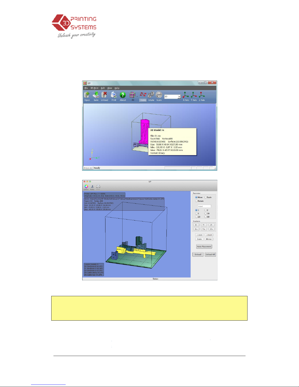
Move the mouse pointer on
model information
is presented
TIP:
You can open several
repeat the open model procedure for each model you want to add. See the
“Placing models on the build platform” section for more information.
Unloading the model
:
(Pink), and click “
Unload
over the model
and a context menu will
3.
Operation
to the model, and click the left
mouse
in a floating window, as
shown below
(Windows version)
(Mac version)
models and print them all at the same time. Just
click the left mouse button on
the model
” on the toolbar or click the right
mouse
appear. C
hoose unload the model or
Operation
19
key. Some
:
to select it
button while
Page 20
UP Mini
3D Printer User Manual
unload all model
s (if you have more than one file open and want to remove all
of them).
Saving the model: C
hoose the model, then
UP3 format and its
size is 12%~18% of the original STL
convenient format
for users to
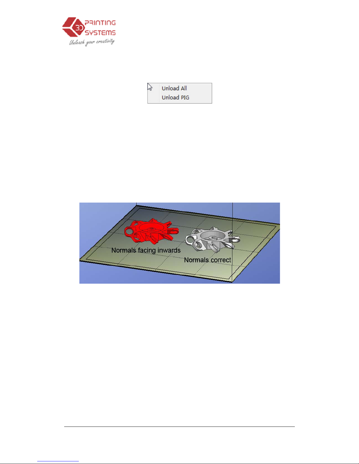
Note on STL files:
For a model to print correctly,
need to have their normal facing outwards. The U
colour Red to indicate
a
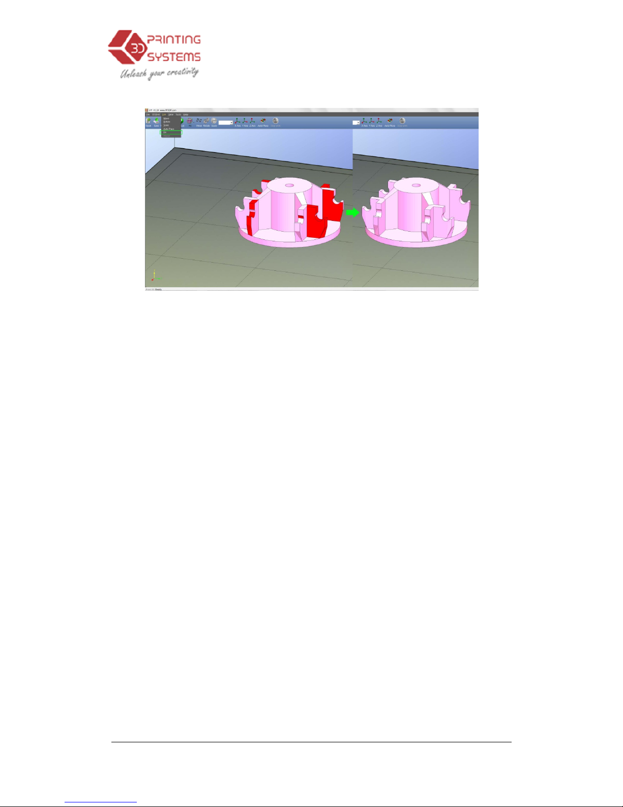
software when opening a model is a light grey/pink colour. If the normal
f
acing the wrong way, then the model is coloured in red.
Fixing STL Files:
The Up software has an option that attempts to fix models
with bad surfaces. Under the “Edit” menu you will see a “Fix” option. Select the
model with inverted surfaces, and click t
3.
Operation
click “Save”.
The file is
file
archive or transfer files.
all the faces of the models
P
software uses model
problem with a
model. The default colour used by the
he “Fix” option to try and fix it.
Operation
20
saved in
. This is a
s are
Page 21
UP Mini
3D Printer User Manual
Merging models:
Several separate models can be merged into a single file by
using the “Merge” option from the “Edit” menu. Simply open all the models you
want to merge and arrange them the way you want on the platform a
the “Merge”
option. When you then save the file, all the components will be saved
as a single STL file.
3.2.3 View
Options
To observe the target
model
view.
Rotate:
Press the middle mouse button a
rotated and
observed from different angles.
Pan: Press Ctrl and
the
mouse:
This causes the
pan the view.
Scale: Rotate th
e mouse wheel
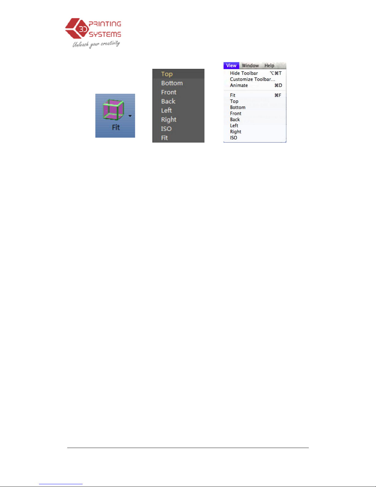
View:
The system has 8 preset standard views
on the toolbar
. Click
the View button is
3.
Operation
in different ways, use the
mouse to control the
nd move the mouse: T
he
middle mouse button at the same time and move
view to pan.
You can also use the arrow keys to
: The view gets zoomed in or
out
stored under the “View” button
the View button on the toolbar (the startup value for
“Fit") to find these options:
Operation
21
nd click on
view can be
the
.
Page 22
UP Mini
3D Printer User Manual
(
Windows version
3.
Operation
) (Mac
version
Operation
22
)
Page 23
UP Mini
3D Printer User Manual
3.2.4 Model
transformation
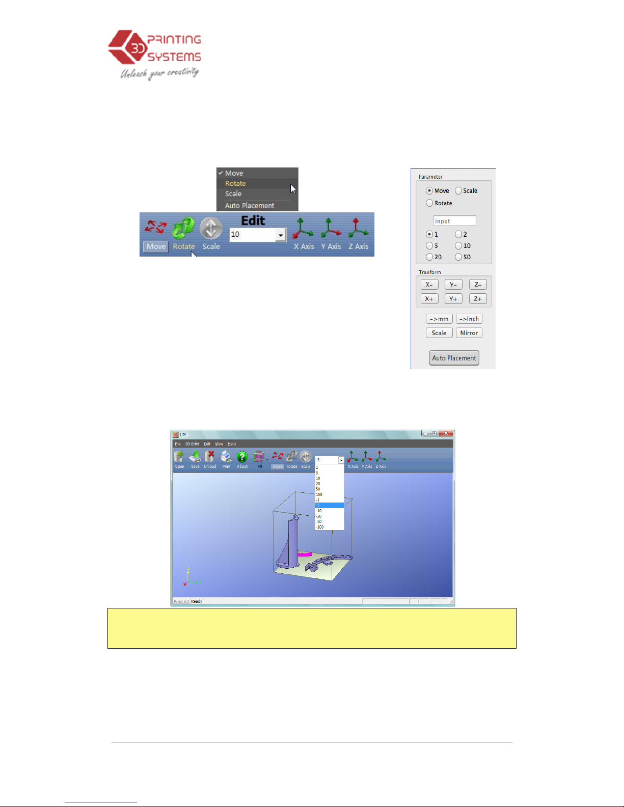
Model Transformation can be
(Windows version)
Moving the model:
Click
or input, the distance
you want to move
Then choose the axis
(direction) in which you want to
move. Each time you click the axis button the model will
move again.
For example: Move the
m
Procedure: 1. Click on “Move”
3. Click the “Z axis”.
Tip:
If you hold down the ‘Ctrl’ key, you can simply drag the model to whatever
position you want.
Rotating the model:
Click
how many degrees you want to rotate
rotate around.
3.
Operation
s
achieved through the Edit menu
or
the “Move” button and choose,
in the text box.
odel -5mm along Z axis (or down 5mm).
; 2. Input “-5” in the text box;
the “Rotate” button
on the toolbar, choose or input
in the text box
, then choose the axis
(Ma
Operation
23
the toolbar:
to
c version)
Page 24
UP Mini
3D Printer User Manual
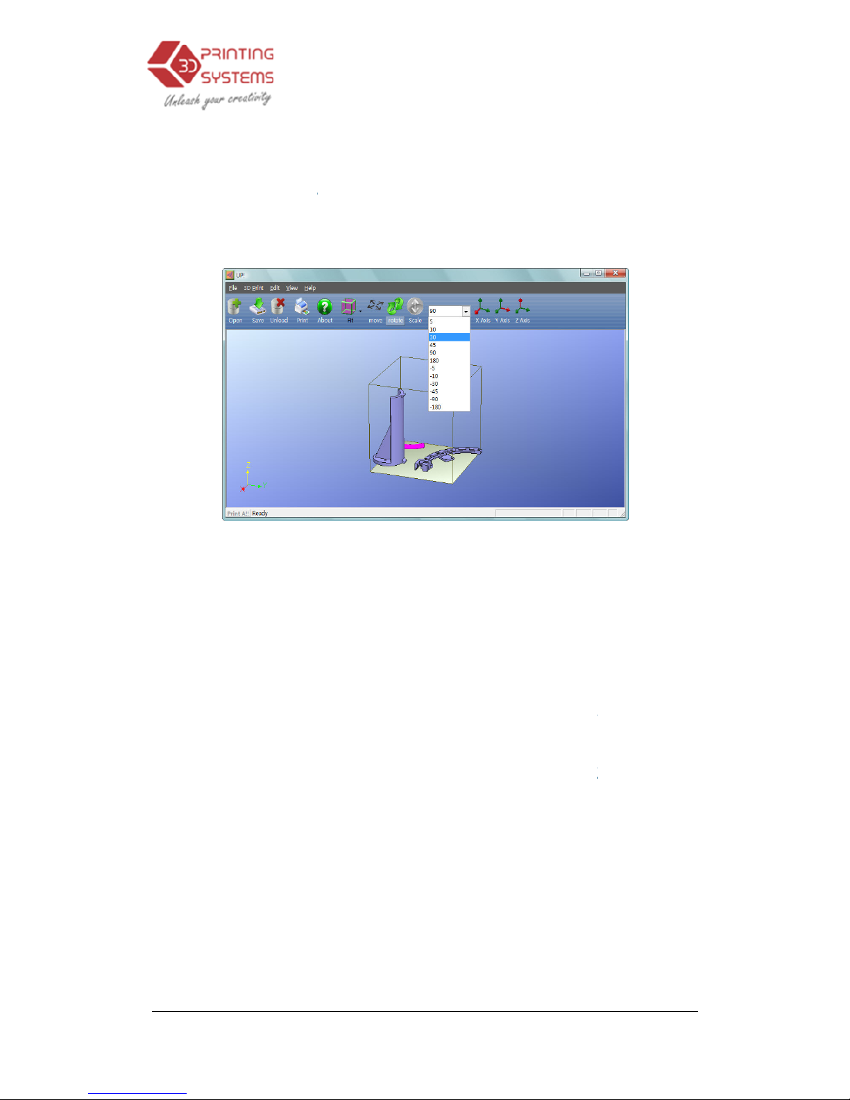
For example
: Rotate the model around Y axis by 30
Procedure: 1. Click
“Rotate”; 2.
Note:
positive numbers rotate counterclockwise and negative numbers rotate
clockwise.
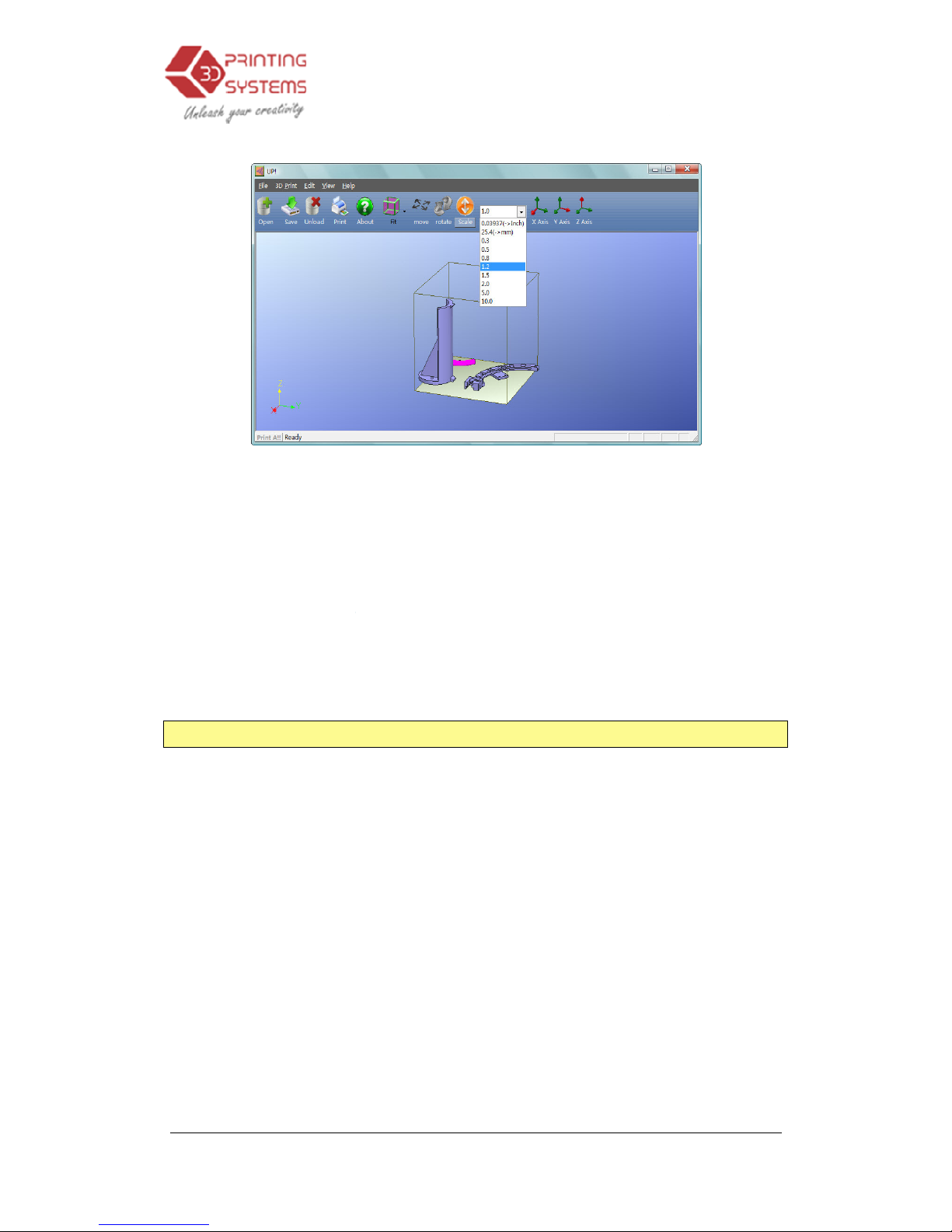
Scaling the model:
Click “Scale”
box, and then
either scale the model uniformly by clicking the scale
again, or
choose the axis
scale in one direction.
Example1: Scale up
the model
Procedures: 1. Click “Scale”; 2. Input
Example2: Scale up
the model
Procedures: 1. Click “Scale”; 2. Input 1.2 in the
3.
Operation
o
.
Input 30 in the text box;3.
Click “Y axis”
, choose or input a
scaling factor
around which you want to scale if you only want to
uniformly by 2.0 times.
2.0 in the text box
; 3. Click “Scale” again.
by 1.2 times along the Z axis only
.
text box;
3. Click “Z axis”
Operation
24
.
in the text
button
Page 25
UP Mini
3D Printer User Manual
Unit Conversion:
This option is provided as a convenient way to convert
metric models to imperial, and vice versa. To
metric, select the 25.4 option from the scale menu and click “Scale” again
convert from metric to imperial, select the 0.03937 option and click “Scale”
3.2.5 Placing model
Appropriately placing yo
quality.
TIP:
In general, try to place your model in the centre of the platform.
Auto Place: Click the
“Auto Place”
automatically place
the model
model on the platform,
using
By Hand: Press the C
holding the left
mouse
desired position.
Using the “Move”
button
input the distance
in the text box
which you want to move
3.
Operation
convert an imperial model to
s onto the build platform
ur models on the platform can have an effect on print
button, on the far right of
the
on the platform
. When there is more than one
“Auto Place” is recommended.
trl key
and choose the target model by
button
. Move the mouse and drag the model to the
: Click the “Move” button
on the toolbar, choose or
, and then choose the axis
for the direction in
.
Operation
25
. To
.
the
toolbar, to
pressing and
Page 26
UP Mini
3D Printer User Manual
NOTE:
When more than one model is
should be ke
pt to at least
Or if you want the models to be closer, under the “Edit” menu, do a
“Merge” which combines multiple separate models into one model.
3.3.4
Other Maintenance Options
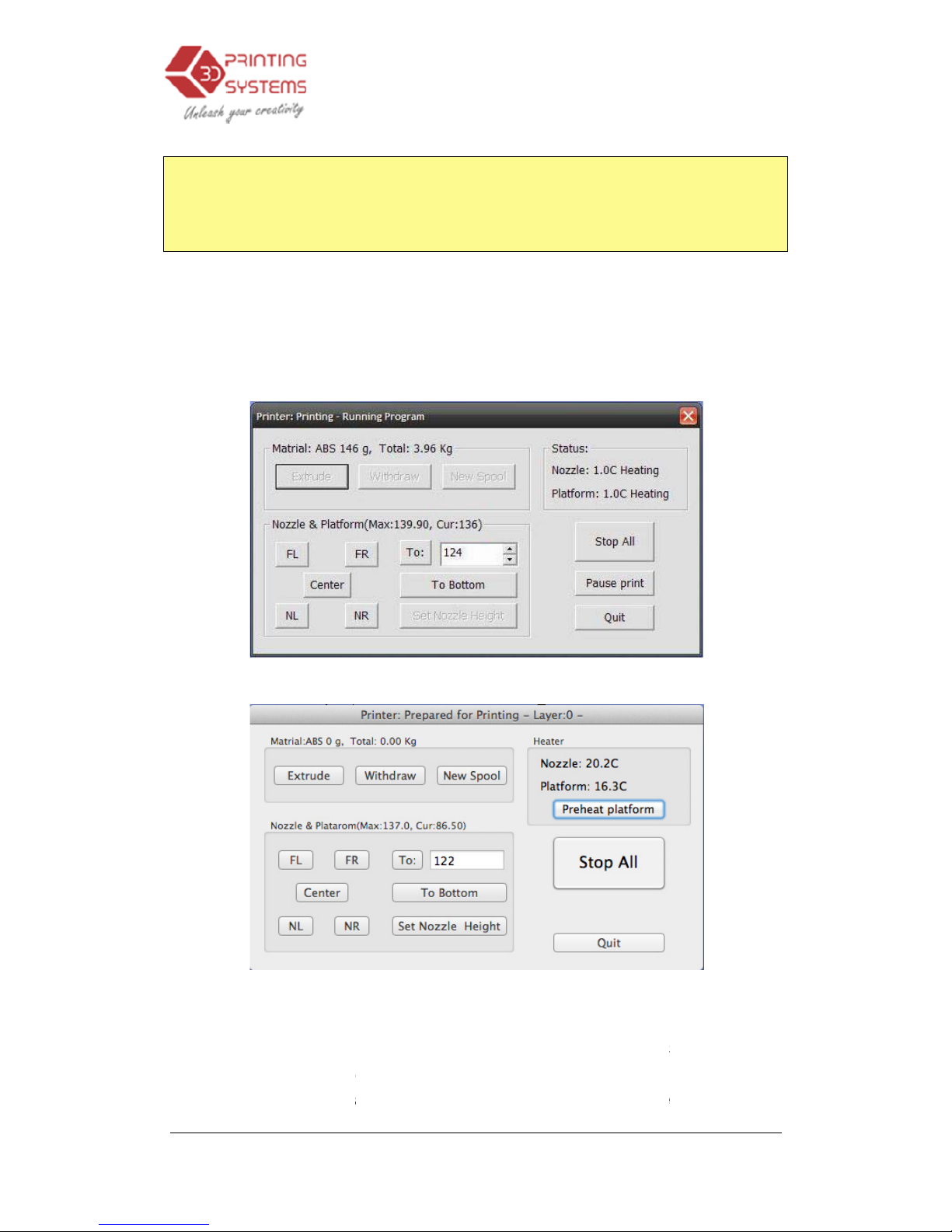
Click “Maintain” on the “3D Print” menu, and the following dialog box pops up:
Extrude: Squeezes
material
nozzle is heated.
When the temperature is high enough
is squeezed out
of the nozzle
extruding, and it beeps
again when finish
3.
Operation
open
, the gap between each
12mm to prevent
the models sticking together
(Windows version)
(Mac version)
out of the nozzle
. Click on this bu
(260°
C)
. The system beeps
before material starts
again when finish
ed
. When changing the material
Operation
26
model
.
tton, and the
, the material
(See
Page 27
UP Mini
3D Printer User Manual
section 6), this f
unction is used to deliver
function can also
be used to
Withdraw: Withdraws
the material
runs out,
or the nozzle needs to be chan
is
up to temperature (2
material gets stuck, pull
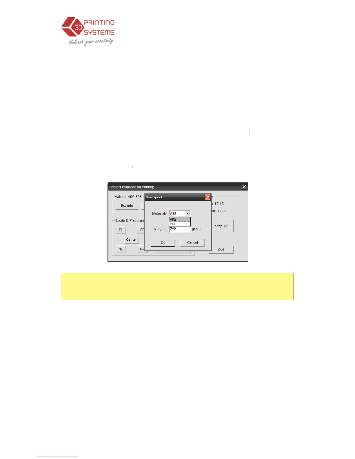
New Spool:
This is used so the printer can keep track of how much material
has been used, and
warn you if you don’t have enough material left to print
your model. Click this button and enter the value of how many grams of
material you have on the current spool. If it is a new spool, the quantity should
be set to 700 grams.
You can also specify whe
with is ABS or PLA.
TIP:
An empty spool weighs about 280 grams so, if you are installing a partially
used spool, weigh it, and subtract 280 grams from the weight. This gives
you the value to enter into the material tex
Status: Displays
the temperature of
Stop All: Stops
heating and all the movement of the printer. Once
button, the
current model being printed
print job once the printer has
you will need to re-
initialize
Pause Print:
This button allows you to pause a print in mid
can then resume the print job where it left off. This is very useful if you, for
ex
ample, want to change the material colour mid
pausing a job mid-
print is to allow fasteners to be inserted into printed cavities
and then printed over to lock the fastener into place.
3.
Operation
the new material to the nozzle
test whether the nozzle is working
correctly
from the extrusion head
. When the material
ged, click this button. When the nozzle
60°C) and beeps, gently
pull out the material. If the
it out it by hand.
ther the material you are printing
t box.
the nozzle and platform.
is cancelled. You
CANNOT
been stopped.
After you use the “Stop All” option,
the printer.
-
progress, but yu
-
print. Another popular use for
Operation
27
. This
.
you click this
resume a
Page 28

UP Mini
3D Printer User Manual
Nozzle & Platform:
The f
position of the nozzle and the platform. The nozzle moves to the left and right;
the platform moves forward and backward.
The “To” button control
s
height calibration p
rocedure described in 3.3.2
The “Bottom”
button returns
Set Nozzle Height:
Takes whatever value you have in the “To” box and
transfers it to the Nozzle box of the setup screen.
3.3.5
Preparing the Platform
Before p
rinting, the platform must be prepared so
the platform enough to be printed without the model moving.
in the box provided,
these are
The P
erfboard is cut at 45 degre
the platform. When printing starts, plastic will have more chance to be pushed
into all perforations, and this provides a stronger mechanical bond with the
bottom surface that prevents it from later lifting
Cleaning the P
erfboard
To clean the platform use the included Perfboard pokers, or alternatively use
the spatula and simply just scrape off the surface plastic until smooth on both
sides. If you preheat the table for longer the plastic left in the Per
becomes soft and the extruded plastic sticks to it, thus not requiring the holes
of the Perfboard to be empty/clean.
3.
Operation
ive buttons (FL,
FR, Center, NL, NR
the height of the platform, and is
used in the nozzle
.
the platform to the lowest position.
that
the model adheres to
Use the
used to clip the perfboard onto
the platform.
es angle with the edge, and just fits the size of
.
Operation
28
) control the
six clips
fboard
Page 29
UP Mini
3D Printer User Manual
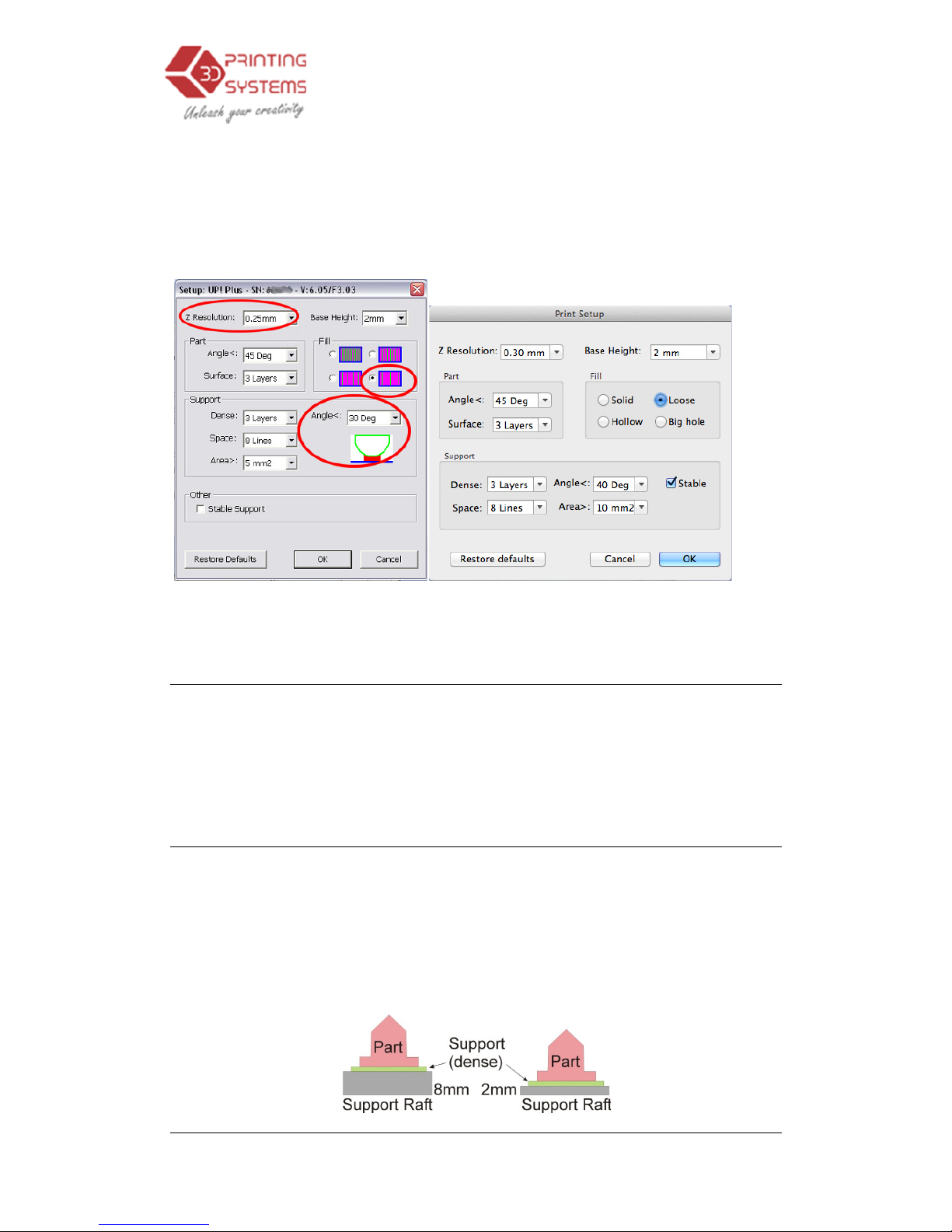
3.3.6 Print Setup
Click menu “3D Print-
>Setup
Recommended Settings
W
indows version Mac version
Print Options
Z Resolution: Sets
the print
be between 0.2mm per layer to 0.4mm per layer (depending on the printer
model).
Optimize: Disabled.
Height Options
Base
: This is the thickness of the
printed under the part.
non-solid
material in which all the lines of support material are horizontal
(along the Y axis). It keeps building up
as many mm as you have chosen.
surface of the real
part, it starts to build support layers perpendicular to the raft
layers layer.
(Windows version
)
3.
Operation
Options
”. The following dialog box pops up:
in red
resolution (layer thickness)
of the printer. This can
raft of material
before the support layer is
When the printer starts printing, it first prints a raft of
horizontal
rows of support material for
Then, j
ust before it gets to the bottom
(Mac version)
Operation
29
Page 30
UP Mini
3D Printer User Manual
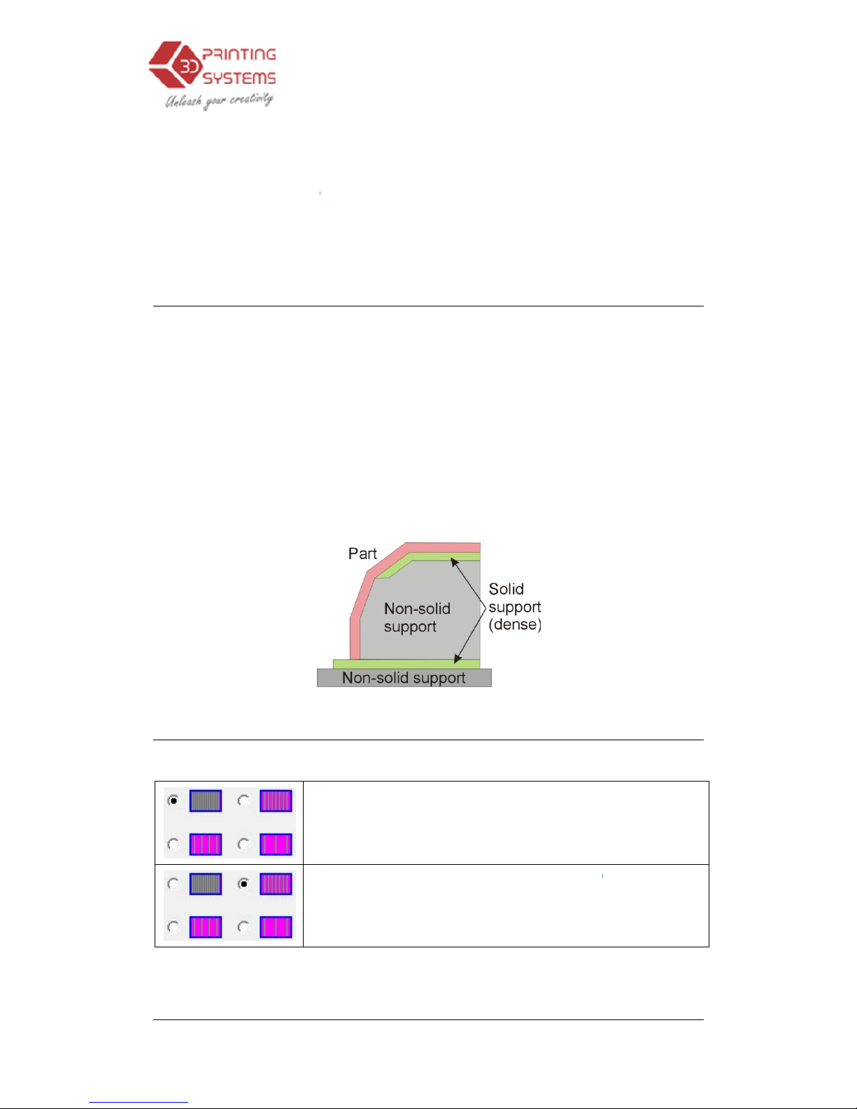
The default value for this parameter is set to 2mm.
Nozzle: represents the
distance between
is at the
bottom position
printing. See section
3.3.
Part Options
Surface:
This parameter determines how many layers form the bottom face of
a part when it is not solid. For example, if you set it to 3, the machine will print 3
complete layers before going into non
affect the side wall thickness on non
thickness (approximately 1.5mm) irrespective of the fill mode.
Angle:
The part Angle determines at what point solid (dense) support material
gets use
d. If the angle is small than the printer will add solid fill layers under the
part surface. The thickness of this solid (dense) support is determined by the
“dense” parameter under the Support options as described below.
Fill Options
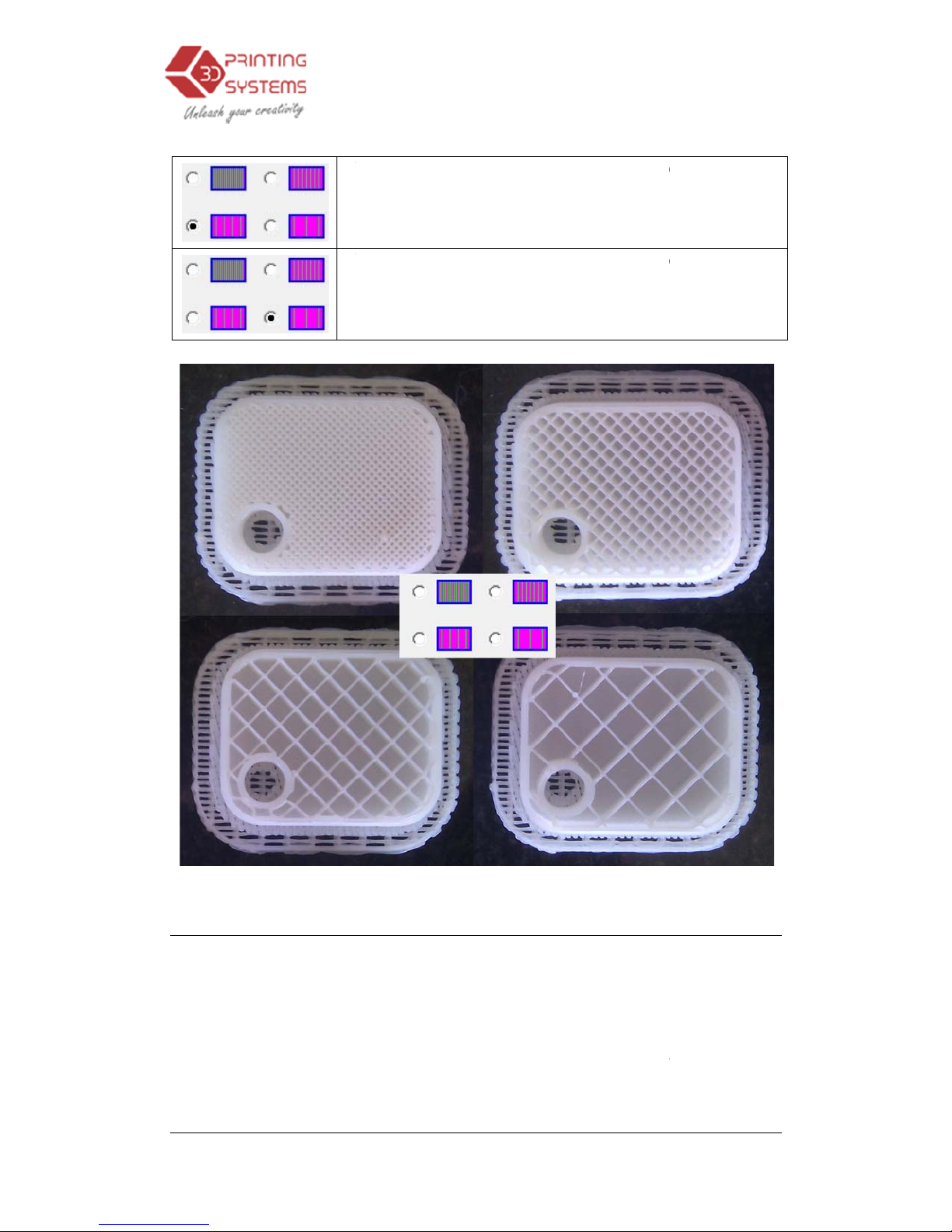
There are four wa
ys to fill the interior of the parts
The Part is made of
the strongest part. This setting is recommended for
functional engineering parts.
version this was referred to as “
The part has an outer wall thickness of solid plastic
(about 1.5mm), but its interior is filled with a reasonably
small scaffold structure
this was referred to as “Loose”
3.
Operation
distance between
nozzle
and the print platform when it
.
It is essential that this value be correctly set for good
2. for instruc
tions on calibrating your printer.
-solid
mode. This does not, however,
-
solid parts, which are all the same
, as described below
nearly
solid plastic, which gives you
On previous software
Solid”
. On previous software version
Operation
30
.
Page 31
UP Mini
3D Printer User Manual
The part has an outer wall thickness of so
(about 1.5mm), but its interior is filled with a medium
spaced scaffold structure
this was referred to as “Hollow”
The part has an outer wall thickness of solid plastic
(about 1.5mm), but its interior is filled
spaced scaffold structure
this was referred to as “Big hole”
Support Options
Dense:
This represents how many layers of ‘solid’
of the support structure directly beneath the model.
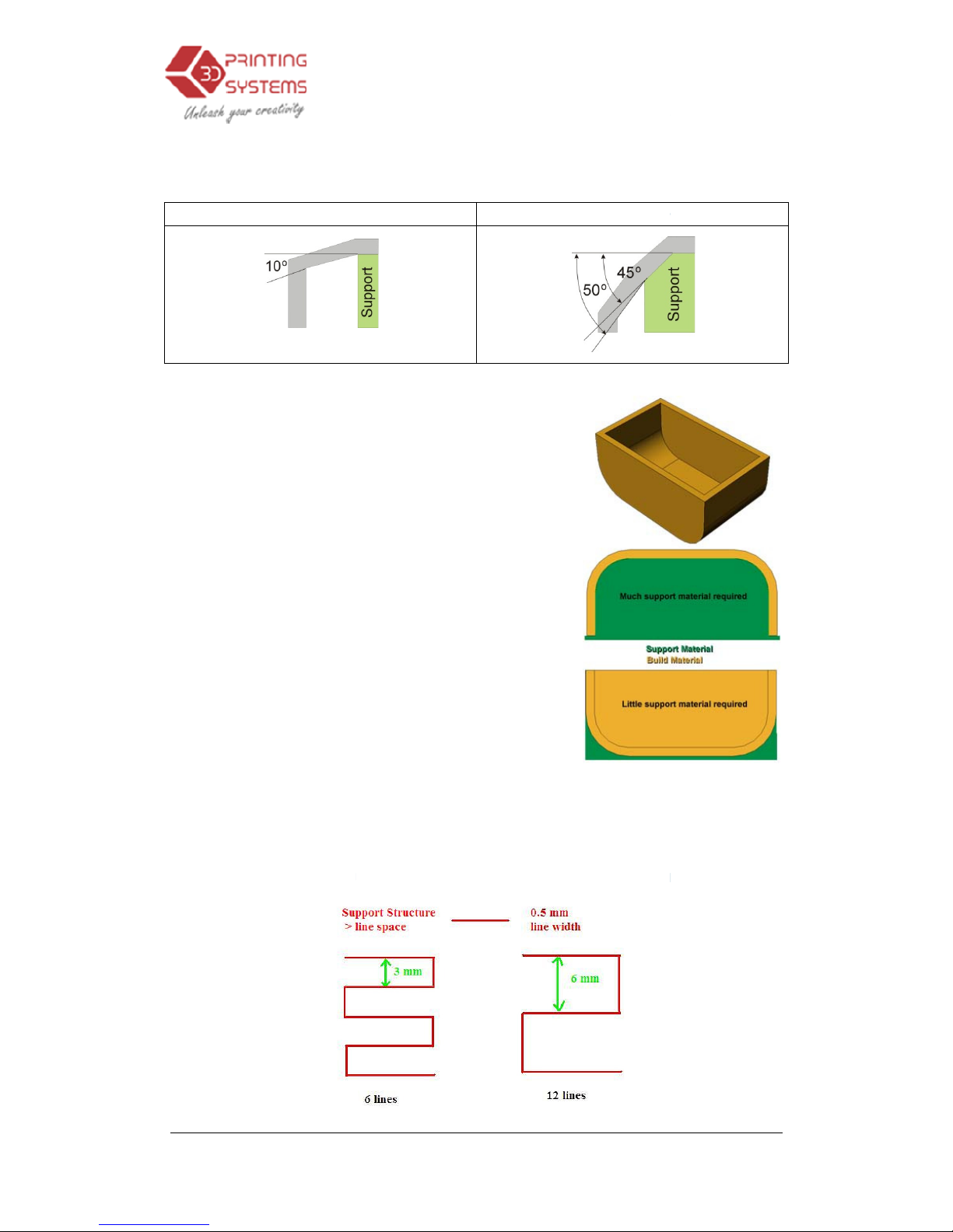
Angle: Angle at
which support material gets used. For example if 10
support material only gets used if angle of surface is
horizontal
(so support material is almost not used unless there is a direct
overhang), If set to 50°
3.
Operation
. On previous software version
. On previous software version
(dense)
material form part
greater
than
than support material is used for any surface
Operation
31
lid plastic
with a large
° is used,
than
10° from
is greater
Page 32
UP Mini
3D Printer User Manual
than 50° away from
horizontal.
Set to > 10°
There is always a delicate balance between
minimizing the amount of support material,
versus the quality of the part, versus the
di
fficulty of removing support material.
The orientation of the part on the print platform
is also critical in determining both how much
support material gets used, and also how
difficult the support material will be to remove.
As a general rule, it is ea
support material from the outside of a part than
from the inside. As can be seen in the picture
to the right, the part would use a lot more
support material if printed with the opening
facing downwards than if it were facing
upwards.
Space:
The distance between the lines of
this parameter requires som
material used, ease of support material removal, and part print quality.
3.
Operation
Set to > 5
0
sier to remove
non-solid
support material
e
experience in balancing the quantity of support
Operation
32
°
. Changing
Page 33
UP Mini
3D Printer User Manual
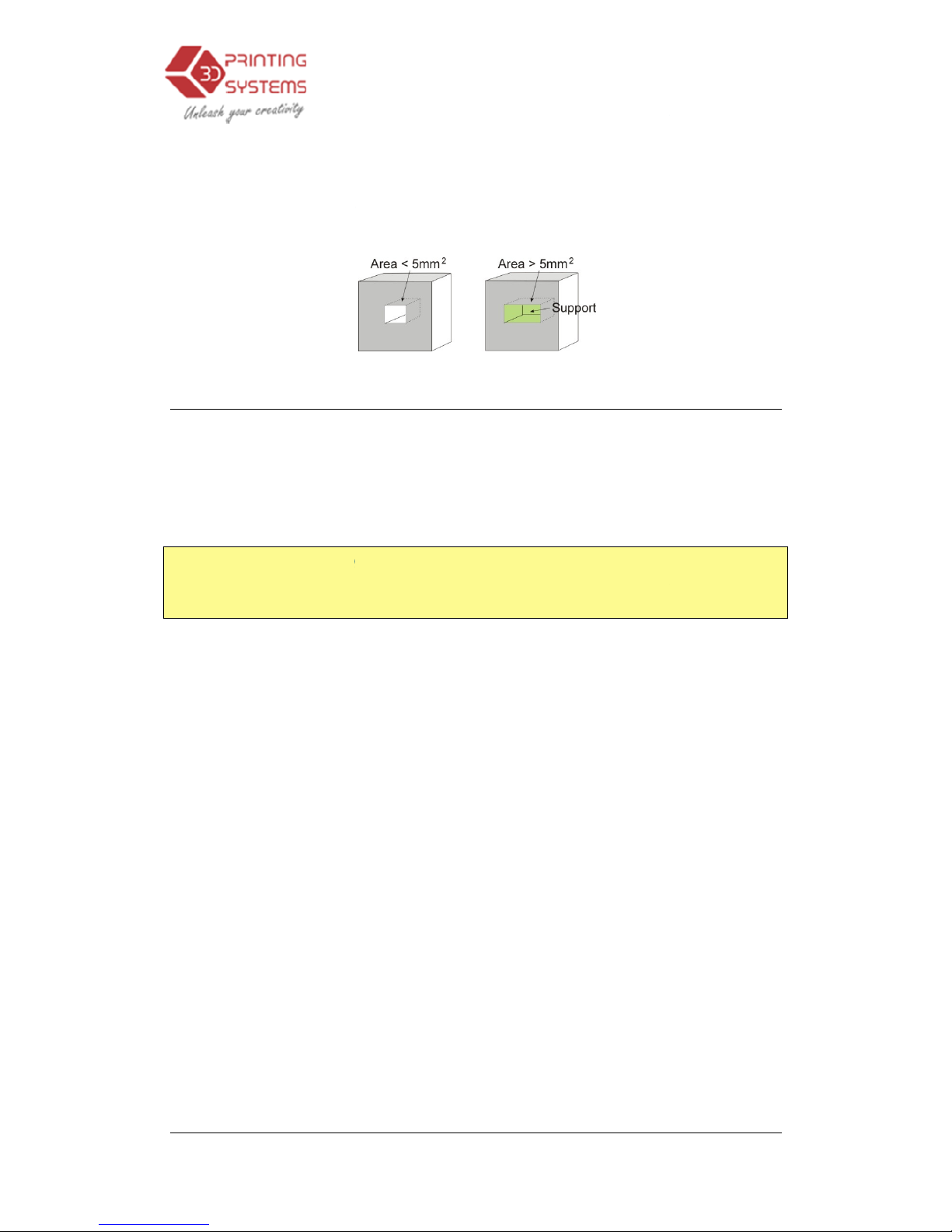
Area:
The surface area above
choose 5mm2,
for example,
less than 5mm
2
. Benefit?
speed is achieved.
Other Options
Stable Support: S
table support creates support that is more solid, and the
model is less likely to distort, but the support material is then more difficult to
remove.
Tip:
All setup and configuration settings are stored in the Up Software, not on
the Up Printer. This m
will need to repeat all the calibration and setup procedures.
3.
Operation
which support material gets used. W
there will be no support if the overhang
A little material is saved and a
slightly
eans that, if you change to a different computer, you
Operation
33
hen you
ing area is
faster print
Page 34
UP Mini
3D Printer User Manual
4. Printing
TIP:
One of the keys to successful printing on the Up is platform preparation
and preheating. Particularly with large parts, t
edges of the part to lift from the platform (which is a little colder than the
center) and cause the parts to warp. The best way to prevent this is to
ensure that a.
) the platform is perfectly level, b
correctly set and that c
run the printer in a room that is not too cold (
and free of drafts.
Please ensure the following points are taken care of
Connect
the 3D printer,
model and place it properly on the virtual platform of the
Check if the
re is enough
tell you if there is not eno
change the reel to a
For large models (over 40mm2) results can be improved by preheating the
build platform. Click the “Preheat” option on the “3D Print” menu and the
printer begins to heat the platf
beginning to print.
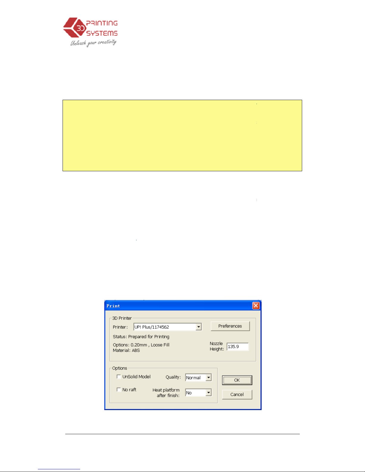
Click menu “
3D Print
“Preferences”
to set the printing parameters.
3.
Operation
here is a tendency for the
.
) that the nozzle height is
.
) the platform is very well preheated. It also helps to
i.e.
warmer than, say, 18
before printing:
initialize it,
and set up the printing system.
software
material
for the model (the software will, generally,
ugh material when you begin the print)
new one.
orm.
Let the platform get up to 100
->Print”, and the print
dialog box pops up. Choose
Click “OK” to
begin
(Windows version)
Operation
34
°C
Load the
window.
. If not,
°C before
to print.
Page 35
UP Mini
3D Printer User Manual
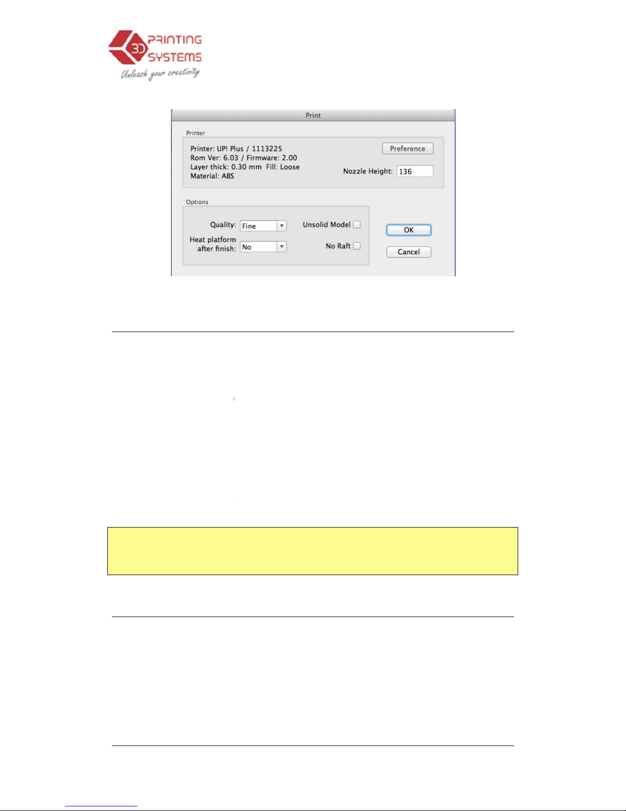
Print Options:
Speed:
Fine, Normal or Fast
printer moves. As a general rule, the slower you print, the better the quality of
the parts. For tall parts, running at Fast speed can be problematic as the
printer can vibr
ate to the extent that print quality is affected. For large surface
area parts, the Fine setting can be problematic as the printer takes longer to
print the part and the corners are therefore more likely to lift a little bit.
UnSolid Model:
This function i
A perfect STL file is a fully enclosed surface
surface skin, and no overlapping surfaces.
should allow you to print it anyway
TIP:
Once the print has started, you can unplug the PC from the printer. The
print job is stored in the printer’s internal memory, so the PC is no longer
required
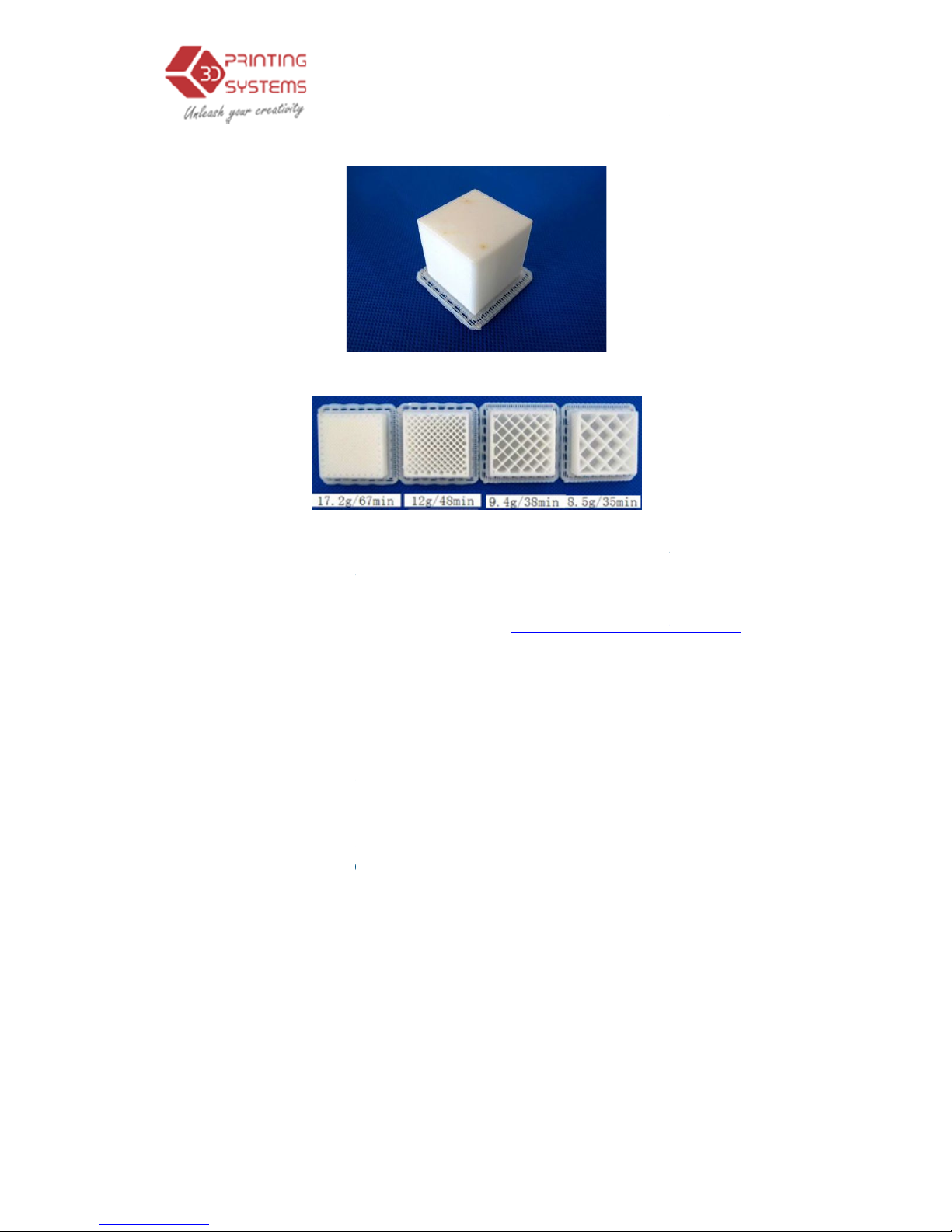
Calculating model costs
The main factor that will affect
support material. If, for example, one is printing a cube measuring 30mm x
30mm x 30mm, with a layer thickness of 0.2
material are used depending on the print mode.
3.
Operation
(Mac version)
. This simply determines the speed at which the
s useful for printing STl files that are not perfect.
(water tight)
, with no holes in the
If your file is not perfect, this option
.
model cost is the part interior
fill structure, and
5
mm, the following quantities of
Operation
35
Page 36
UP Mini
3D Printer User Manual
Model info: 30×30×30mm layer thickne
$2.02
The easiest way to calculate how much material will be used for your model is
to use the “Print Preview” option under the “3D Print” menu. This will tell you
the total weight of materia
The price as 6/9/12 for ABS plastic from
AU$59 per 1KG working out to be
5. Model Removal
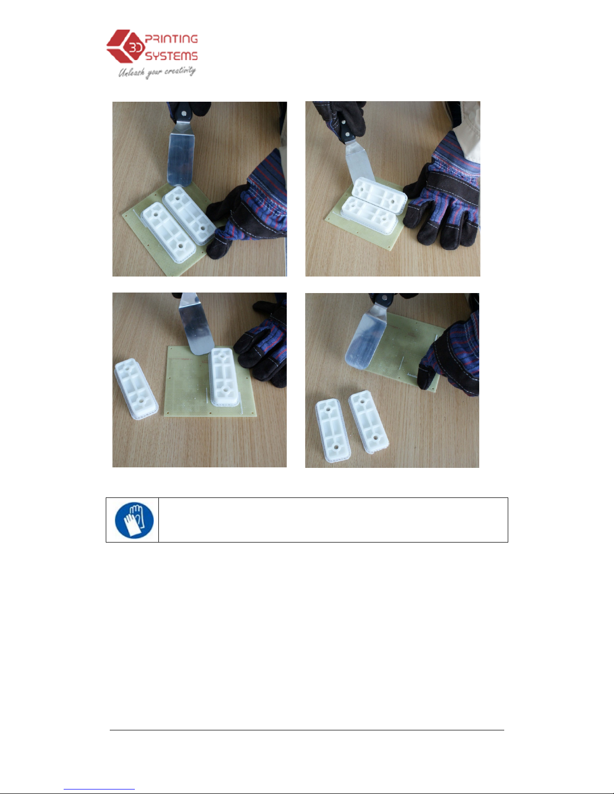
1. When the model
ha
and platform stop heat
2.
Slide to remove the
3.
Gently slide the spatula under the model and slowly wiggle it ba
forth to pry loose the model. Remember to u
model may still be hot
3.
Operation
ss: 0.25
mm
71cents 55cents 50cents
l used, including the raft and any support material.
www.3DPrintingSystems.com
0.059cents per gram.
s finished printing, the
printer will beep, and the
ing.
Perfboard from the printer platform.
se gloves
as the platform and
.
Operation
36
was
nozzle
ck and
Page 37
UP Mini
3D Printer User Manual
CAUTION: It is strongly recommended that you
remove the model from the
3.
Operation
wear
perfboard.
Operation
37
the gloves to
Page 38
UP Mini
3D Printer User Manual
Removing Support Material
Printed models are composed of two parts. One part is the model itself, and
the other part is the support material used to support any overhanging parts of
the model.
The support material is the same physical material as the model material, but
the supp
ort material is printed at a much lower density. It is very easy to
distinguish the model from the support material so it is easy to remove.
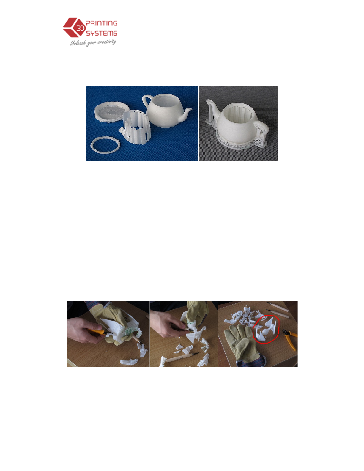
Have a look at the teapot in the above pictures. The left picture shows the
teapot with support material removed,
with its support material still attached.
The support material ge
material can easily be cracked off by hand. Support material close to
is easier to remove us
ing
It takes some practice to get comfortable with removing support material
can become quite an enjoyable and therapeutic task
3.
Operation
and the right picture shows the teapot
ts
removed using a combination of tools. Some
tools such as the knife and cutters.
!
Operation
38
the model
, but it
Page 39
UP Mini
3D Printer User Manual
CAUTION: ALWAYS WEAR SAFETY GLASSES WHEN REMOVING
SUPPORT MATERIAL, ESPECIALLY
CAUTION: The support material and the tools are sharp. Wear
gloves and safety glasses when removing the part from the printer.
3.
Operation
WITH PLA MATERIAL.
Operation
39
Page 40
UP Mini
3D Printer User Manual
6. M
aintenance
Changing the Material
First withdraw
the leftover
choose “
3D print
automatically
begin
correct temperature
material.
Place a new
spool of
filament tube
, until the material is about 10cm out of the
into the hole
at the top of the extruder head
Select the “maintain” menu form the “3D Print” menu
“Extrude
” button in the “maintain” dialogue. After the printer nozzle has
warmed up to 260°C, the printer will beep. Push the filament into the hole
at the top of the extruder head, with a little pressure, and the extruder will
automatically extrude material.
nozzle should be
thin, bright and smooth.
If the nozzle is blocked, remove the nozzle and clean it.
The extruder and platform are hot. Use gloves when working
in this area of printer.
Vertical Calibration
This
is only recommended to carry out if you find that your models are not
vertical.
The Vertical calibration procedure allows you to ensure that the printer platform
is perfectly horizontal and that the printer prints consistently in the X, Y and Z
direction.
3.
Operation
material from the printer. Initialize
the printer and
->Maintain”. Click
“Withdraw” and the system
s to heat the nozzle. When the
nozzle
,
the printer will beep, and you can gently
material on the spool holder,
and pull it through the
tube
.
. Then
The plastic thread
squeeze
Operation
40
reaches the
withdraw the
, then insert it
press the
d out of the
Page 41
UP Mini
3D Printer User Manual
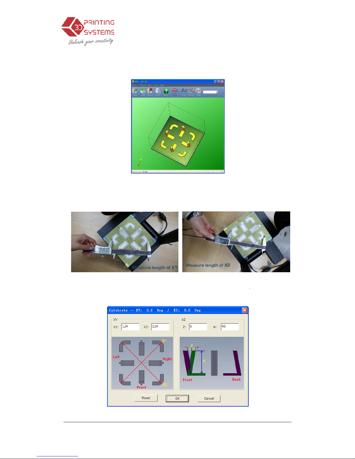
First, print the supplied
in C:\Program Files\UP
\
After the calibration model is printed, measure the X1 and X2 length
in the pictures below.
Open the “Calibrate” box
and X2 values into the appropriate boxes.
3.
Operation
Calibration model on your
printer. The calibration file is
Example.
form the “3D Print” menu and enter the measured X1
Operation
41
, as shown
Page 42
UP Mini
3D Printer User Manual
IMPORTANT NOTE:
Before you enter any new calibration values, always click the
“Reset” button, otherwise the new values get added to the old ones. Before you
new values, the bar at the very top of the screen should read: XY: 0.00 deg / XZ: 0.00 deg.
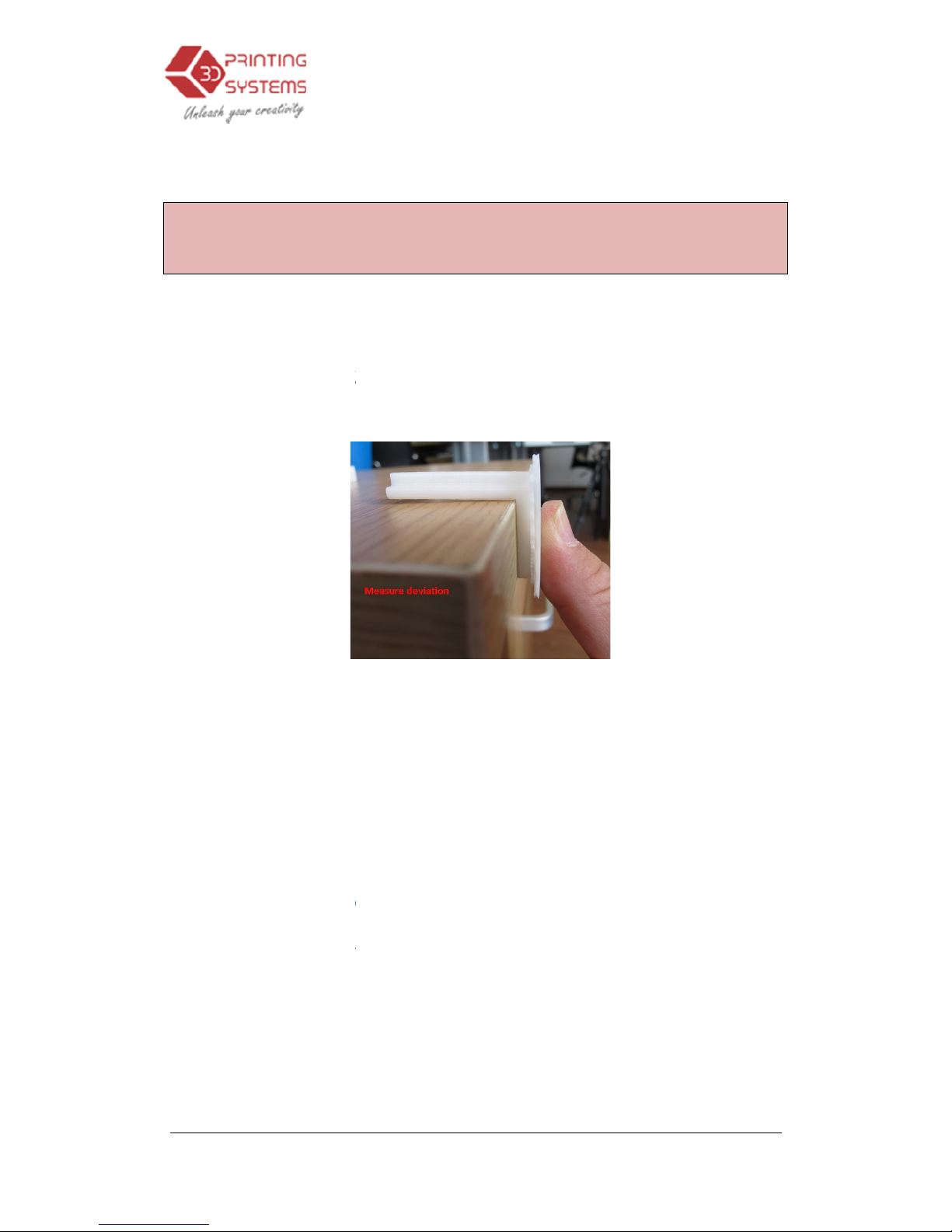
Next,
take down the Front
deviation. Put the exact value into the Z box. If it deviates to the right side,
value to
be put into the Z box will be a positive value. If the deviates to the left,
the value to
put into the Z box will be a negative value.
Finally, measure the height of Front
40mm if it is not scaled.
“Calibrate dialogue box.
Click “OK” to record all these values and exit the calibrat
Cleaning the nozzle
After a lot of printing, the nozzle may be covered with a layer of oxidized ABS.
When the p
rinter is printing, this oxidized ABS may melt on the nozzle, and may
create discolored spots the model. To avoid this you need to regularly clean the
nozzle.
Firstly,
move the platform to the bottom, then do a Withdraw in order to
nozzle to melt
the oxidized ABS.
Lastly, use some heat-
resistant material, like 100 percent cotton cloth or soft
paper. A pair of tweezers will also be required. Then clip paper or some other
3.
Operation
Centre ‘L’ shaped component
, and measure its
Center component
, which
Enter th
e exact measured value into the “H” box of the
ion
window.
Operation
42
enter any
the
should be
heat the
Page 43
UP Mini
3D Printer User Manual
heat-
resistant things with tweezers to clean up the nozzle.
TIP:
Many users also soak their nozzle in acetone to clean them, or even use an
ultrasonic cleaning bath to help clean their nozzles
Removing / Changing the nozzle
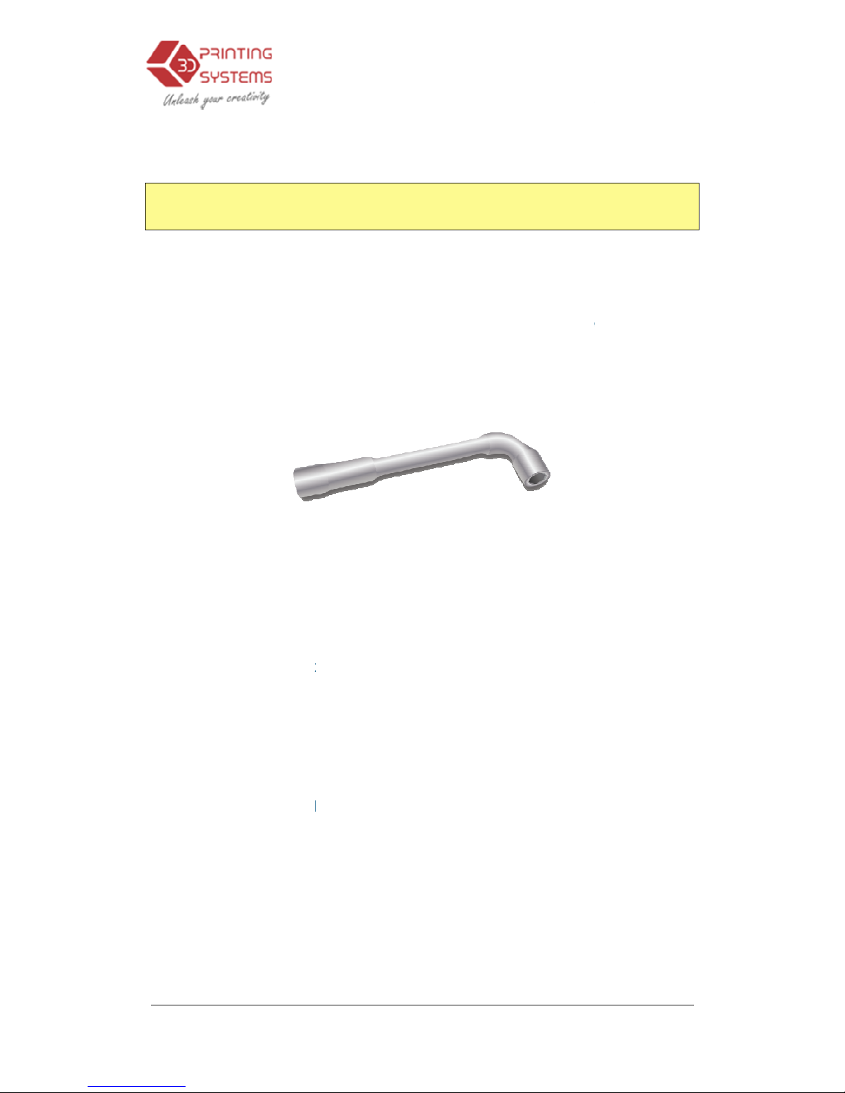
Should the nozzle become blocked, you may need to remove it in order to
unblock, or change it.
maintenance screen, then once the printer is at 260c,
provided in the toolkit that comes with your Up Printer.
when it is hot.
Cleaning the
Perfboard
To clean the platform use the included Perfboard pokers, or alternatively use
the spatula and simply just scrape off the surface plastic until smooth on both
sides. If you preheat the table for longer the plastic left in the Perfboard
beco
mes soft and the extruded plastic sticks to it, thus not requiring the holes
of the Perfboard to be empty/clean.
Lubrication of bearings
The bearings on the Up Printer may occasionally require a bit of lubrication to
keep it operating smoothly. The recomme
When lubricating the bearings, first clean off as much old grease as possible
from the bearings, and then apply new grease to the bearing and slide the
platform
in the appropriate direction to spread the grease.
Spare parts
Almost all the plastic parts on the printer are printed by the Up printer itself. If
3.
Operation
To remove the nozzle,
first click Withdraw in the
use the nozzle wrench
ONLY
remove the nozzle
nded grease to use is lithium grease.
Operation
43
Page 44

UP Mini
3D Printer User Manual
you need to print spare parts for your printer, the files for all spare parts can be
found in the C:\
Program Files (x86)
3.
Operation
\UP\Example\ Spare Parts
folder.
Operation
44
Page 45

UP Mini
3D Printer User Manual
7.0. Tips
& Tricks
Large parts can sometimes have their corners lift from the platform, which
causes the part to distort. This is caused by uneven heat across the surface of
the platform. Preheating the platform before beginning large parts is essential
to minimize this lifting.
•
Make sure the table is level!
the nozzle and in maintenance, move the head to each corner to ensure the distance
between nozzle and table is the same at each corner. There are thr
table underneath the platform holder.
•
Make sure the table is nice and toasty!
heated after printing) -
Insulate the table during preheating, use a piece of cardboard on the
platform whil
e preheating.
•
Keep the printer away from any breezes
(Cover in a box)
• Print hollow -
The less mass of plastic the less heat in the centre, the less warping.
•
Print the object with the least surface area on t
the Wind Barrier to reduce support.
•
Print closer to the Perfboard
layer of raft ensures plastic goes right into the holes.
•
Keep the perfboard clean
ensuring it’s kept clean and smooth on both sides.
•
Large parts -
For large parts, ensure the platform is super toasty level and screw down the
platform.
• Regularly check your
platform
of which you may not even be aware of. To check your nozzle height, refer to section
3.3.2
3.
Operation
-
Remove the Perfboard and clips, bring the table up to near
ee screws to level the
(do a previous print or two and keep the table
, this cools the model too fast and it then warps.
he platform,
creates more support. Use
-
By holding down the head with finger pressure on the first
- Clean
the perfboard, by scrapping off the surface and
height! It can change fo
r a number of reasons, some
Operation
45
Page 46
UP Mini
3D Printer User Manual
8.
Troubleshooting
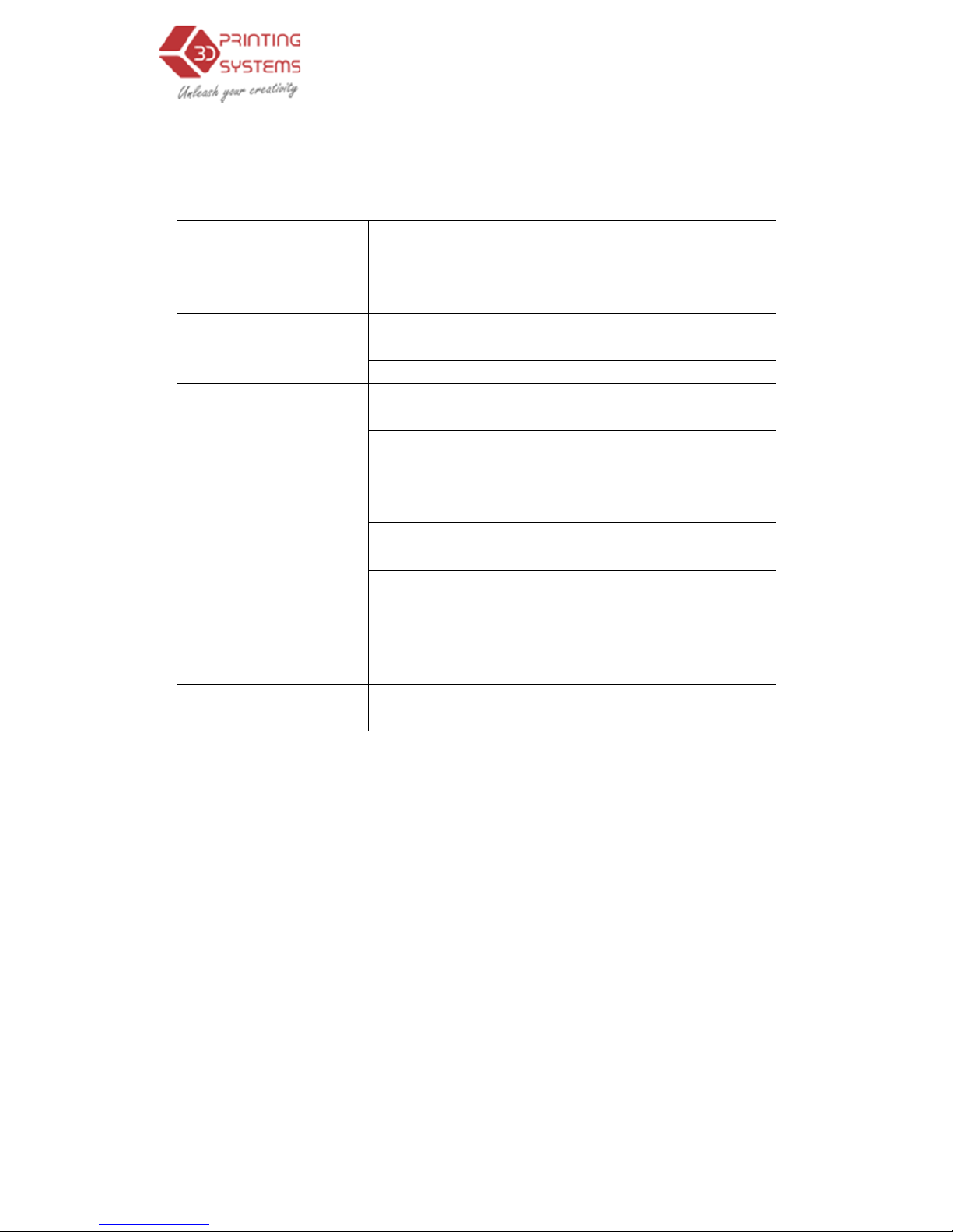
Problem or error
message
No power
Extruder or platform
fails to reach
operating temperature
Material not extruding
Cannot communicate
with printer
Others
Solution for "
Winusb
If you encounter a “
Winusb
steps below:
Option 1:
Uninstall Older Driver
1. Open the Windows
c
then select the
“Hardware” page.
4. Troubleshooting
Solution
Verify power cord is securely plugged in.
1.
Verify printer has initialized. if not, initialize
the printer
2. Heater is damaged
, replace the heater
Material is stuck in the extruder
. See 3.3.3
Maintain (Extrude)
The gap is too wide betwee
n the bearing and wire
feed rollers.
1. Make sure the USB cable is
connected
printer, and to the PC
2. Unplug the
USB cable, then plug in again.
3. Reset the printer—
power off then power on.
4. Restart the PC
5. Make sure in Device Manager in Windows that
the printer driver is correctly installed.
6. Try with a different USB cable and with a
different PC.
Contact Technical Support :
[email protected]
.dll not found" pro
blem
.dll not found” error message, please follow the
and Automatically
Install New Driver
ontrol panel, go to the “System Properties” dialog box,
46
to the
Page 47
UP Mini
3D Printer User Manual
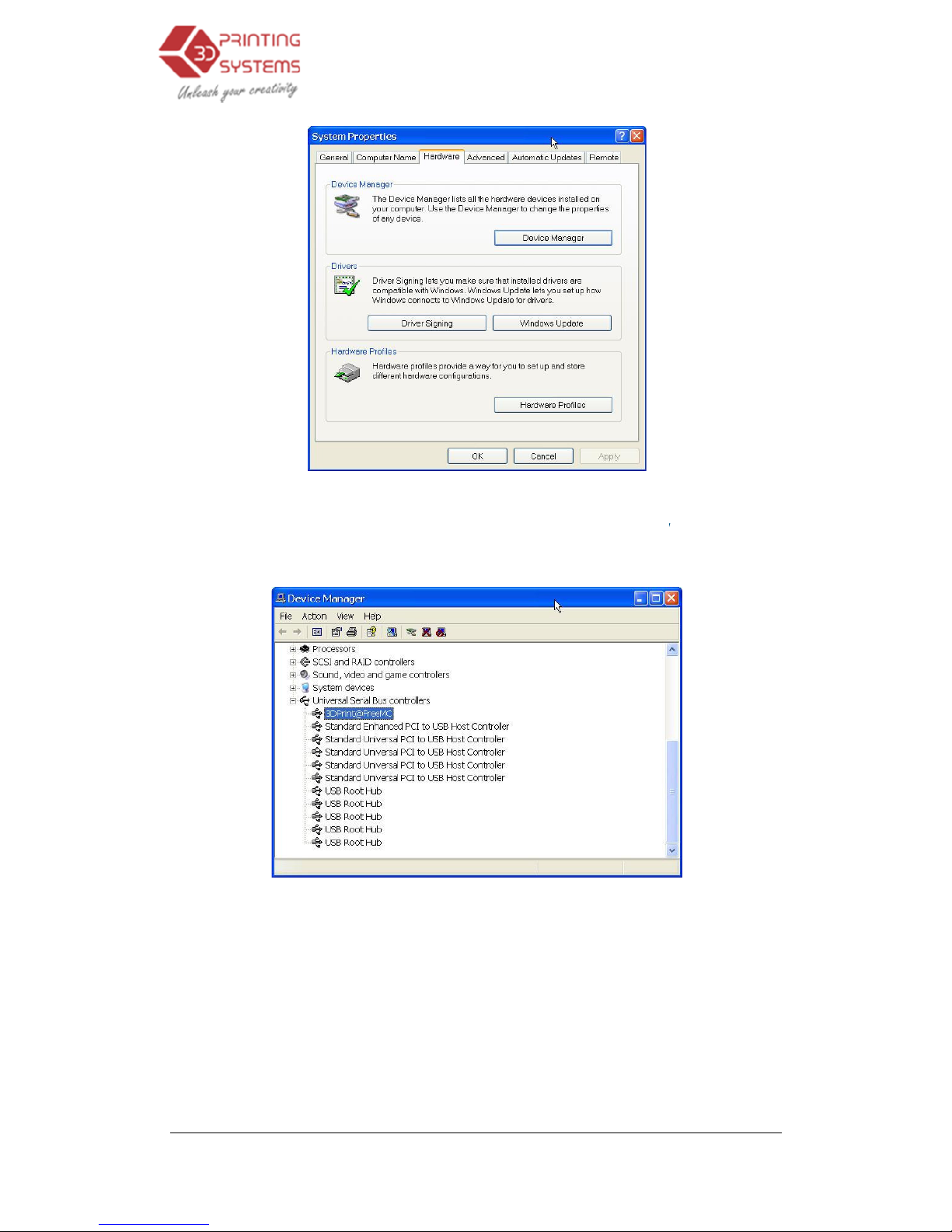
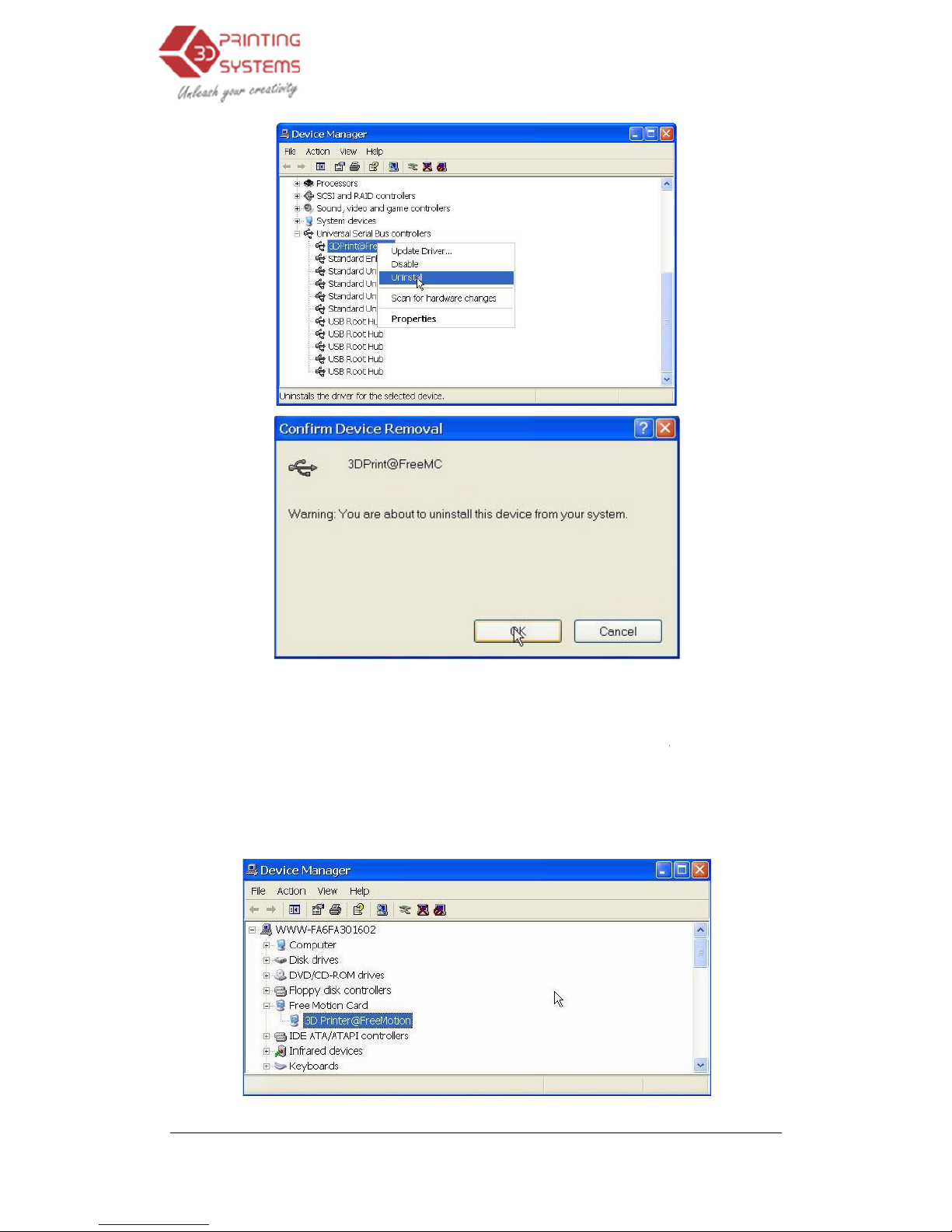
2. Click “Device Manager” button, and the following dialog box will popup. Find
the “3DPrinter@FreeMC” in the USB section.
3. Click the right mouse button and select the “Uninstall” option. The confirm
dialog box will appear. Click “
4. Troubleshooting
OK”.
47
Page 48
UP Mini
3D Printer User Manual
4. Install the latest UP!
s
5. Unplug the USB cable, then plug again. Windows will find a new device.
Manually select driver folder
C:\Program files(X86)\
UP
6. There should now be a new d
below:
4. Troubleshooting
oftware.
(Default is C:\Program files
\
\Driver);
river section in the device manager as shown
48
\
UP\Driver or
Page 49
UP Mini
3D Printer User Manual
Option 2:
Update the driver
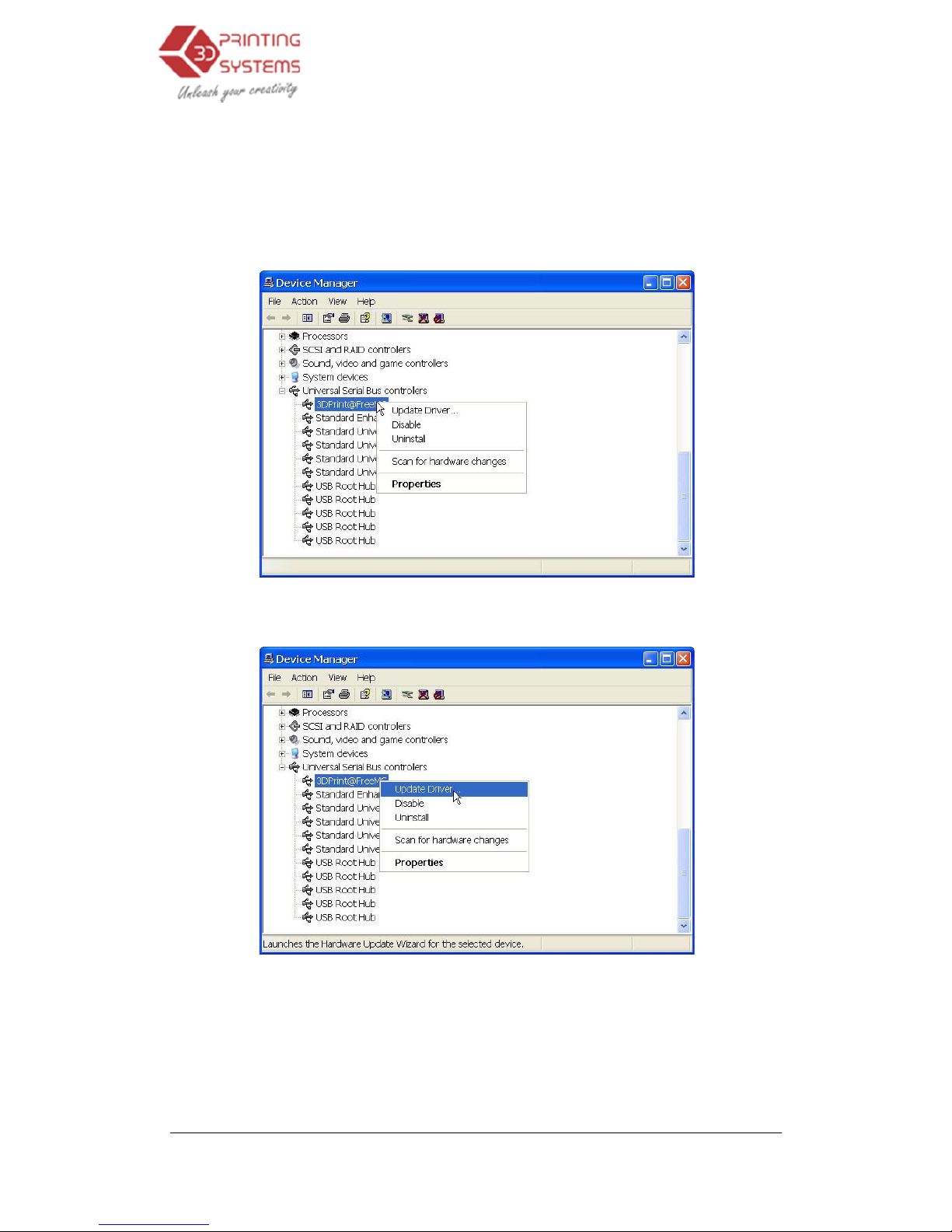
1. Install the latest
UP software.
2. Fi
nd the “3DPrint@FreeMC”
should be located
in the USB section).
3. Select
“Update Driver
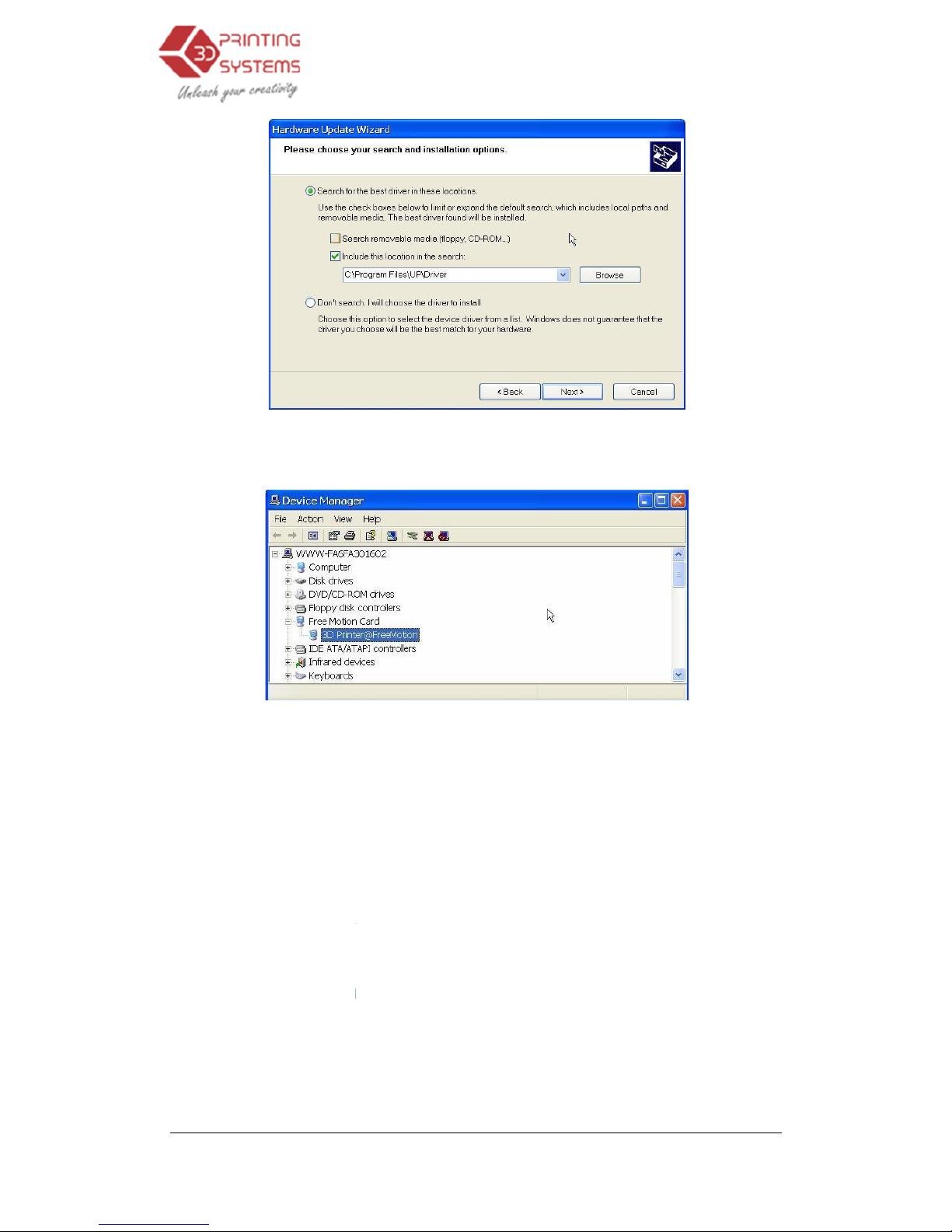
4. Select the up driver folder
4. Troubleshooting
manually.
driver
in the “Device Manager” dialog box
.” in the right click menu.
(the default is C:\program files\UP\
Driver).
49
(it
Page 50
UP Mini
3D Printer User Manual
5. A “Free Motion Card” section
Manager.
Modifications to your printer
Your UP Prin
ter has been designed
printer. If you do choose to make any modifications to your printer, it is best to check with
3D Printing Systems before doing so, otherwise making any modifications to your printer
will void your
12 month warranty.
WARRANTY AND AFTER SALE SUPPORT
3D Printing Systems
prides itself on its after sales support which is
parts and workshop. Our nationwide network of authorised resellers also stock the
consumable
s for your product and through our distribution system can usually order products
that they do not have in stock.
In the unlikely event that you experience a problem with
initial date of purchase,
3D Printing Systems
defective materials or workmanship
be defective within this warranty period will be replaced free of charge. This warranty does not
4. Troubleshooting
should now have been
inserted in
to work without you making any modifications to the
back it’s
Helpdesk, spare
your 3D Printer
, for one year from the
Limited will repair this product free of charge for
(excluding freight to our repair centers)
. All parts found to
50
to the Device
Page 51

UP Mini
3D Printer User Manual
include g
eneral maintenance, normal wear and tear, cleaning, or any damage as the result of
accident, neglect or misuse. To maintain a high standard of operation
recommends the use of only genuine approved
consumables. The use of non
will void your
product warranty. Other parts or supplies not specifically sold or approved by
Printing Systems
may also affec
product warranty.
In the event of resale, the balance of the warranty is transferable, with proof of purchase.
At no time does
3D Printing Systems
costs or for any damage during transit; nor any consequential damages seemingly relating to
the product or it’s related components.
4. Troubleshooting
3D Printing Systems
by 3D Printing Systems UP
manufactured
-genuine plastics
may affect the performance of this product and
t the performance of this product and may void the
Limited accept liability for any freight or trans
51
3D
your
portation
 Loading...