


OPERATING INSTRUCTIONS
3D-ONE CAMCORDER CP31
ISSUE 1.0.10
BASED ON SOFTWARE VERSION CP31-0058
© 2010 3D-ONE
CP31
POINT-AND-SHOOT 3D HD CAMCORDER
3D-ONE B.V.
Niels Bohrweg 11
2333 CA Leiden
The Netherlands
www.3d-one.com
info@3D-one.com
Tel +31 71 524 10 91
CCI reg. nr. NL 27346866

i.
Warning
To reduce the risk of re or electric
shock, do not expose this apparatus
to rain or moisture. To avoid electrical
shock, do not open the cabinet. Refer
servicing to qualied personnel only.
When installing the unit, incorporate a
readily accessible disconnect device in
the xed wiring, or connect the power
plug to an easily accessible socket-
outlet near the unit. If a fault should
occur during operation of the unit,
operate the disconnect device to switch
the power supply off, or disconnect the
power plug.
Do not install the appliance in a
conned space, such as a bookcase or
built-in cabinet.
Exposing the OLED screen, the
viewnder, or the lens to direct sunlight
for long periods of time may cause
malfunctions.
Do not aim at the sun. Doing so might
cause your 3D camera to malfunction.
Take pictures of the sun only in low light
conditions.
To reduce the risk of permanent
damage or injury do not drop the
camcorder and provide secure
mounting.
Protect your ears
Excessive sound pressure from
earphones and headphones can cause
hearing loss. In order to use this product
safely, avoid prolonged listening at
excessive sound pressure levels.
Battery
Batteries shall not be exposed to
excessive heat such as sunshine, re or
the like.
Recycling battery
The lithium battery contains perchlorate
and is recyclable. You can help preserve
our environment by returning your used
rechargeable batteries to the collection
and recycling location nearest you.
CAUTION
DO NOT HANDLE DAMAGED OR LEAKING
LITHIUM-ION BATTERIES.
DEPENDING ON PRODUCTION
TOLERANCES AND WEAR OF THE
BATTERIES, AND IN CASE OF A
SIGNIFICANT SIDEWAYS SHOCK ON THE
CAMERA, THE BATTERY CAN SLIDE OUT.
DO NOT APPLY SUCH SHOCKS TO AVOID
LOSS OF DATA, DAMAGE AND INJURY. IF
SHOCKS ARE ANTICIPATED, PUT A PIECE
OF TAPE ON THE HOUSING OVER THE
BATTERY TO FIX IT.
AC/DC Adapter
Do not open the AC/DC adapter.
HDD / SSD
The camcorder is either congured with
a HDD of SSD drive for internal storage.
Please note that HDD/SDD drives are
sensitive to shocks and both types of
drives are sensitive to magnetic elds.
The locking mechanism of the
exchangeable HDD/SDD slot is sensitive
to hard shocks in the direction of the
optical axis. Upon a hard shock in the
direction of the optical axis the hard disk
may slide out. Do not apply such shock
to prevent loss of data, damage and
injury. If such shocks are anticipated,
put a piece of tape on the housing over
the storage medium (and battery, see
above) to x it.
Cleaning & servicing
When cleaning the camcorder, follow
these steps:
1. Turn off the camcorder
2. Disconnect the AC adapter
3. Use a soft, moist cloth. Do not use
liquid or aerosol cleaners.
Servicing
Do not open the casing of the
camcorder, the warranty will no longer
apply. The inner parts are sensitive for
dust, moisture and are securely aligned
to work the best. If servicing is necessary,
please contact your dealer.
II. Warning

3D displays
Keep in mind that looking through the
built-in stereoscopic displays will block
part of your eld-of-view and alter your
perception.
Seizure warning
Some viewers may experience an
epileptic seizure or stroke when exposed
to certain ashing images or lights when
viewing 3D content through the built-in
stereoscopic displays. If you or any of
your family has a history of epilepsy or
stroke, please consult with a medical
specialist before using the 3D displays.
If you experience any of the following
symptoms, immediately stop watching
3D pictures and consult a medical
specialist: (1) altered vision; (2) light-
headedness; (3) dizziness; (4) involuntary
movements such as eye or muscle
twitching; (5) confusion; (6) nausea; (7)
loss of awareness; (8) convulsions; (9)
cramps; and/or (10) disorientation.
Enclosure cooling
The CP31 camcorder uses passive
cooling by means of the external
cooling body. Blocking the cooling
area may result in excessive enclosure
temperatures which may permanently
damage the camera, result in inferior
sensor performance and injury. Ensure
that there is sufcient ventilation to cool
the camera.
Built-in magnets
The camcorder uses built-in magnets
to secure the stereoscopic viewnders
which can interfere or disturb with
equipment sensitive to magnetic elds.
CE Declaration of
conformity
We from 3D-ONE B.V. (CCI reg. nr. NL
27346866), Niels Bohrweg 11, 2333 CA
Leiden, The Netherlands, declare that
the product: 3D-One point and shoot
3D camcorder CP31 is in conformity
with both the EMC Directive and
the Low Voltage Directive issued by
the Commission of the European
Community. Compliance with these
directives implies conformity to the
following European standards:
EN60065: Product Safety (AC adaptor)
EN55103-1: Electromagnetic Interference
(Emission)
EN55103-2: Electromagnetic
Susceptibility (Immunity)
This product is intended for use in the
following Electromagnetic Environments:
E1 (residential), E2 (commercial and light
industrial).
The manufacturer of this product is
3D-ONE B.V, Niels Bohrweg 11, 2333 CA
Leiden, The Netherlands. 3D-ONE B.V. is
also the Authorized Representative for
EMC and product safety. For any service
or guarantee matters please refer to the
addresses given in separate service or
guarantee documents.
Leiden, 2010-09-07
Contact person
M. Beijersbergen
Managing Director of 3D-One B.V.
i.
CE Declaration of conformity III.

i.
FCC Verication
Notes
THIS EQUIPMENT HAS BEEN TESTED AND
FOUND TO COMPLY WITH THE LIMITS FOR
A CLASS A DIGITAL DEVICE, PURSUANT
TO PART 15 OF THE FCC RULES.
These limits are designed to provide
reasonable protection against harmful
interference when the equipment is
operated in a commercial environment.
This equipment generates, uses, and can
radiate radio frequency energy and, if
not installed and used in accordance
with the instruction manual, may
cause harmful interference to radio
communications. Operation of this
equipment in a residential area is likely
to cause harmful interference in which
case the user will be required to correct
the interference at his own expense.
Modications not expressly approved by
the manufacturer could void the user’s
authority to operated the equipment
under FCC rules.
Make a test recording
Always make a test recording, and verify
that it was recorded successfully.
3D-ONE WILL NOT BE LIABLE FOR
DAMAGES OF ANY KIND INCLUDING,
BUT NOT LIMITED TO, COMPENSATION
OR REIMBURSEMENT ON ACCOUNT OF
FAILURE OF THIS UNIT OR ITS RECORDING
MEDIA, EXTERNAL STORAGE SYSTEMS OR
ANY OTHER MEDIA OR STORAGE SYSTEMS
TO RECORD CONTENT OF ANY TYPE.
Verify the unit is operating properly
Always verify that the unit is operating
properly before use.
3D-ONE WILL NOT BE LIABLE FOR
DAMAGES OF ANY KIND INCLUDING,
BUT NOT LIMITED TO, COMPENSATION
OR REIMBURSEMENT ON ACCOUNT OF
THIS LOSS OF PRESENT OR PROSPECTIVE
PROFITS DUE TO FAILURE OF THIS
UNIT, EITHER DURING THE WARRANTY
PERIOD OR AFTER EXPIRATION OF THE
WARRANTY, OR FOR ANY OTHER REASON
WHATSOEVER.
Miscellaneous
3D viewing systems differ in colour
and resolution depending on their
technology. Some of them allow to
swap left and right channels and/or to
adjust the alignment of the input data.
Keep this in mind when checking the
quality of the 3D content.
Television programs, lms, video
tapes, and other materials may be
copyrighted. Unauthorized recording
of such materials may conict with
copyright laws.
The images and schematics used in this
manual for illustration purposes may
appear different in reality.
The OLED touchscreen and the
viewnder are manufactured using
extremely high- precision technology.
IV. FCC Verication

However, there may be some tiny black
points and/or bright points (white, red,
blue, or green in colour) that appear
constantly on the OLED screen and
the viewnder. These points are normal
results of the manufacturing process and
do not affect the recording in any way.
The OLED viewnder might show
different colours on the left and right
screen. This does not mean that the
camera sensors are different in colour.
Always check colours on an external
calibrated reference monitor.
The CP31 camcorder can be powered
using Sony BP-U30 or BP-U60 lithium-ion
batteries. The CP31 camcorder has
no built-in charging functionality. Use
an external battery charger to charge
batteries.
All copyrights/trademarks are the
property of their respective owners.
i.
Notes V.

ii.
Contents
Warning II
CE Declaration of conformity III
FCC Verication IV
Notes IV
1. Overview 1
What’s in the package? 1
Features 2
Parts Identied 5
Camera controls 6
Data storage 9
Connectors 10
Viewnder indications 11
Touchscreen indications and operation 12
External indications 16
Files 17
2. Quick Start Guide 19
Material required for a typical shoot 19
Setup 20
During recording 25
After recording 26
VI.
3. Connecting external devices 29
Connecting external monitors 29
Connecting external audio sources 29
4. Connecting to computers 31
Network access 31
Directly connecting the storage medium to a computer 33
5. Troubleshooting 35
Operating power 35
Viewnder 36
Recording 37
Hard disk 38
Network 38
Connectivity & External Devices 39

6. Error/Warning indications 41
7. Technical specications 43
ii.
VII.

ii.
VIII.

You have the CP31 in your hands - a 3D
HD camcorder, able to make great 3D
content. Use this manual to nd out how
to congure the best settings for your
set-up, and much more!
1.
Overview
What’s in the
package?
1.
Overview
Make sure you have following items
supplied with your camcorder. The
number in parentheses indicates the
number of that item supplied.
CP31 Camera (1)
The CP31 3D HD camcorder comes with
the following parts.
Li-Ion Battery (1)
Exchangeable HDD or SSD (1)
View nder eyecups (2)
Hand strap (1)
What’s in the package? 1.

1.
Accessories
Features
Overview
18 V DC Adapter (1)
Battery charger (1)
CP31 Operations Manual (This
booklet).
Optional Accessories
Network cable
Shoulder strap bag
Mounting shoe
Spare battery
Spare HDD/SDD
External microphone
3D Monitor
HDMI preview monitor
Rain cover
Tripod
SATA hard disk reader
PC Stereoscopic playback system
Stereoscopic projectors
The CP31 is a highly compact and
high-performance twin lens 3D HD
camcorder that uses SATA hard disks
as its recording medium. The imaging
devices used in the CP31 camcorder
are two 1/2.5-inch type CMOS sensors,
each with an effective pixel count of
1920 × 1080, which produce two images
in full HD resolution. The two sensors are
synchronised on pixel clock level to
ensure perfect 3D recordings.
Multiple-format recording
The CP31 camcorder offers a wide array
of recording formats for multiple content
creation applications. The scanning
mode is switchable among 1920 × 1080
and 1280 × 720 resolutions. Frame rate is
progressive (30P, 25P or 24P). In addition,
50P and 60P progressive recording is
available in 1280 × 720 mode.
High-quality uncompressed audio
recording
In addition to HD video recording, the
CP31 can record and play back highquality, two- channel 16-bit, 48-kHz linear
PCM uncompressed audio.
IT friendly
The le-based recording in two separate
MJPEG encoded AVI les allows material
to be handled with great exibility in an
IT-based environment, easily available
for copying, transferring, sharing, and
archiving. Each time a recording is
started and stopped, the video and
audio clips are recorded as separate
les.
Instantly start recording
In recording on SATA hard disks or
SSDs using an EXT3 le system, the
CP31 makes each new recording
on an empty area of the hard disk.
This is extremely convenient, as the
camera operator need not worry about
accidentally recording over good
takes or search through footage for
the correct position to start the next
recording.
2. Features

Integrated twin lens zoom optics
The CP31 is equipped with two zoom
lenses specically designed for the
camcorder, to offer optimum shooting
performance. Independent controls for
zoom, focus, and iris adjustment give the
user a high level of smooth operational
control. The lenses have versatile
functions for easy and precise focus
adjustments.
3D features
We use integrated dual lens systems that
are fully synchronised when adjusting
zoom, iris and focus. The vergence can
be adjusted and a 3D preview is possible
using the integrated stereoscopic
viewnder. Exposure time, gain and
colours can be adjusted and are
synchronised on both sensors.
1.
Overview
Features 3.

1.
Overview
1.
2.
3.
4.
5.
6.
7.
12.
13.
14.
15.
16.
17.
8.
9.
10.
11.
18.
19.
20a.
20b.
20c.
21.
22.
23.
24.
4. Features
25.
26.

Parts Identied
For function and usage, see the pages
shown in parentheses. Items marked with
an (*) are not installed on all models.
1. Handle
2. Stereo microphone
3. Focus (a) & Iris control (b)(p. 6)
4. Record indicator light (p. 8)
5. Lens hood
6. Stereoscopic lenses
7. Control buttons:
a. AF : Autofocus (p. 6)
b. EXP: Exposure (p. 7)
c. WHT BAL: White balance (p.7)
d. P (Programmable) (p.7)
8. Stereoscopic viewnder
9. Touch screen (p.7)
10. Headphone output (p.10)
11. Ethernet port (p.10)
12. Microphone shoe
13. Recording start/stop (p.8)
14. Power switch (p. 6)
15. Exchangeable HDD/ SSD
16. External battery
17. Record start/stop (p.8)
18. Front attachment point for mono
viewer
19. Audio adjustment(*):
a. Gain internal/external
microphone
b. peak LEDs
20. Audio inputs:
a. 48V+ Phantom power (p.8)
b. PAD buttons (p.8)
c. XLR left & right input (p.10)
21. Left & Right HDMI outputs (p.10)
22. Zoom (a) & Vergence control(b)(p.
5)
23. Handstrap attachment points
24. Tripod 1/4”-20 UNC threaded
attachment point
25. Accessories 1/4”-20 UNC threaded
attachment point
26. Stand-off feet
1.
Overview
Parts Identied 5.

1.
Overview
Camera controls
POWER switch (14)
The focus of both optics can
be manually adjusted using the
potentiometer switch labelled FOCUS.
You can adjust the focus from ∞ to 0.5
m by actuating the switch. Manual
focussing will automatically deactivate
the auto-focus mode (See also AF
button on p. 6).
The POWER switch is used to power up
and down the CP31. A blue indicator
light signals the presence of power when
the switch is set to the ‘on’ position.
14.
The POWER switch will abruptly power
down the camera when set to the ‘off’
position.
CAUTION
ACTUATING THE POWER SWITCH
WHILE RECORDING WILL RESULT IN A
CORRUPTED RECORDING.
FOCUS control (3a)
IRIS and BRIGHTNESS
control (3b)
3b.
If auto-exposure is deactivated (see
EXP on p. 7) then the iris of both
optics simultaneously can be manually
adjusted from F=1.6 to 23.6 using the
potentiometer switch labelled IRIS. The
IRIS F/# is displayed in an insert on the
top of the viewnder. In this mode the
GAIN can be manually set using the
touchscreen (page 13).
If auto-exposure is turned on (see EXP
on p. 7) then the IRIS control adjusts
the BRIGHTNESS. This means that the
camera will automatically adjust the IRIS
and the GAIN. The set brightness value
is displayed in an insert in the top of the
VIEWFINDER.
3a.
6. Camera controls
AF button (7a)
7. a b c d

To activate/deactivate continuous
auto-focus you have to press the
button labelled AF for 2 seconds. The
VIEWFINDER will show ‘AF’ in the top
status line if AF is activated, in addition
a red LED in the AF button will be lit. In
this mode the left objective will be used
to determine the best focus and the
right objective will follow. The region
that the camera considers to determine
the focus can be adjusted using the
touchscreen menu (page 15).
If the AF labelled button is shortly pressed
then a single auto-focus operation will
be carried out (so called ‘one-push
focus). The viewnder will show ‘autofocus start/end’ in the display.
EXP button (7b)
The EXP button is used to toggle
between auto-exposure mode on and
off. If auto-exposure is on, then ‘AE’ will
be displayed in the top status line of the
VIEWFINDER, in addition a red LED in
the EXP button will be lit. Auto-exposure
regulates the iris of both optics and the
gain of both sensors synchronously to
achieve a BRIGHTNESS value set by the
IRIS control and shown in the centre
insert of the VIEWFINDER.
COLOURS ON BOTH SENSORS. ALWAYS
USE A PROPER TARGET, VISIBLE UNDER
THE SAME ILLUMINATION CONDITIONS
IN BOTH CHANNELS SIMULTANEOUSLY.
PROVIDE SUFFICIENT ILLUMINATION.
NORMALLY THE WHITE BALANCE
SEQUENCE COMPLETES WITHIN ONE
SECOND ON BOTH CHANNELS. IF IT TAKES
SIGNIFICANTLY LONGER ON ONE OR ON
BOTH CHANNELS, YOU SHOULD REPEAT
THE WHITE BALANCE.
P button (7d)
The P (Programmable) button turns
on/off a cross-style line overlay in the
VIEWFINDER. This helps determining the
vergence plane when the stereoscopic
VIEWFINDER is used.
When the P button is pressed longer than
2 seconds then the VERGENCE DISTANCE
lock can be engaged/disengaged.
The status of the lock is indicated in the
VIEWFINDER with a green or red distance
indicator. It is green (if the distance can
be kept constant during zooming) or
red (if the user has zoomed too far in).
TOUCHSCREEN (9)
1.
Overview
WHT BAL button (7c)
The WHT BAL button triggers the
automatic adjustment of the white
balance, if pressed longer than 2
seconds. The white-balance is started
simultaneously on both sensors, however
the sensors perform the balance
individually. When the white balance
starts ‘White balance running …’ is
displayed in the VIEWFINDER. When
the white balance is completed ‘White
balance done’ will be displayed. In
addition a red LED inside the WHT BAL
button will blink during white balance
operation.
CAUTION
PERFORMING A GOOD WHITE BALANCE
IS IMPORTANT TO ACHIEVE MATCHING
Camera controls 7.
9.
The TOUCHSCREEN is used to control
many functions of the camcorder by
simple touching and sliding gestures. A
slider can be adjusted by either tapping
on a region of the slider, by sliding the
position indicator left/right or by ne
tuning the value using the ‘+’ / ‘-‘
buttons on the left and right side of the
sliders.
You can cycle through the different
menus by tapping the ‘<<’ and ‘>>’
1.
Overview
buttons in the top left/right corners.
Buttons can be turned on/off by tapping
them once. A simple toggle button will
light green when in the ON position. A
function change button will indicate the
selected function by displaying a text
and highlighting one state in orange.
and right channels of the internal
MICROPHONE (INT MIC) and of the
external microphones (EXT MIC)
connected using the XLR connectors.
Every AUDIO GAIN potentiometer has
a corresponding PEAK LED to indicate
clipping of the audio signal.
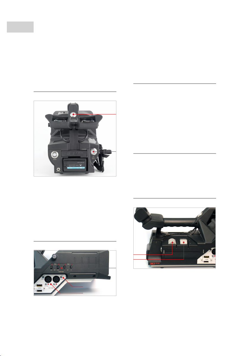
RECORD buttons (13) &
(17)
13.
17.
The CP31 camcorder has two RECORD
start/stop buttons, one located near the
handle, one on the rear. They function
identically: To start recording press one
of the once and both will lit red. To stop
recording press the button once more.
AUDIO GAIN controls
(19a)
19.
48V+ buttons (20a)
Enables provision of phantom power
(+48 V DC) on the corresponding XLR
output.
CAUTION
PROVIDING 48V DC TO EQUIPMENT
NOT DESIGNED TO HANDLE 48V MIGHT
RESULT IN PERMANENT DAMAGE TO THAT
EQUIPMENT.
PAD button (20b)
The two PAD buttons are used to
attenuate the input of an external
microphone, that is to bypass the
internal microphone preamp.
ZOOM control (22a)
22.
a
b
With the 4 AUDIO GAIN potentiometers
you can adjust the gain of the left
8. Camera controls
20b.
20a.
The zoom position of both optics
can manually be adjusted using the
potentiometer switch labelled ZOOM.
You can adjust the zoom from 1.0 x to
12.0 x by actuating the switch.
NOTE:
When the vergence is not set to innity,
 Loading...