

Page 1

Welcome to a Revolution with No Limits!
ENGLISH USER MANUAL
Rev 1.1
Page 2

Introduction to the manual
Before starting, read carefully this manual to guarantee the proper use of the equipment.
Pay close attention to the warnings and security measures indicated in the manual.
The pictures of the equipment are subject to change.
3DLimitLess will not be responsible for performance issues due to changes done by the user to
the parameters of the firmware and software provided.
Page 3

TABLE OF CONTENTS
1. Safety instructions
2. Package contents
3. Product detail
4. Printer unpacking and proper handling
5. First look at the Printer 3D LimitLess ILC
5.1 Features and functions
6. Start Up
6.1 Manual printing (from SD)
6.2 Computer printing
7. Recommendations for proper use and maintenance
8. Printing problems
8.1 Lack of extrusion starting the printing
8.2 First layer does not adhere to the printing base
8.3 Lacking extrusion
8.4 Over extrusion
8.5 Holes on the top part of the pieces
8.6 Detecting fine lines on the pieces
8.7 Excessive heating
8.8 Marks on the top side
8.9 Layers sliding
8.10 Clogged nozzle
8.11 Plastic bubbles in the piece
8.12 Spaces in the top surface between parameters and filling
8.13 Warping
8.14 Layers gap
8.15 Split filament
9. Product proper disposal
10. Informative links
11. Warranty
12. EC Declaration of conformity
Page 4

1. SAFETY INSTRUCTIONS
Non-compliance of the security measures could lead to personal and material damages
(burns, cuts and bruises, even fires.) The following security and safety directions can
protect your health, of others, and the product’s. In the case of giving this machine to
someone else, be sure to pass the manual as well.
This machine should not be handle by people insensitive to heat and/or dependent
people who can not react quickly to overheating. In the same matter, the use of this
machine should be limited to people who have physical, sensorial or mental
difficulties, as well as lack of knowledge and experience, unless it has been explained
properly and understands the risks that entails.
Prevent children from unsupervised access to the printer.
This machine generates high heat temperatures. Let it cool down before
handling the printer.
The machine could keep warm for few minutes after printing.
The printer includes movable parts that could cause injuries. Assure yourself that
the machine has fully stopped and it has no electrical power supply before
handling it.
Do not open the lower and upper lids of the printer. The interior contents are all
electrical (power supply, control panel, and a Solid State Relay) could cause an
electric shock. The interior component should be manipulated by a professional.
There are air intakes on the sides and a fan in the back of the printer, these
elements should not be cover up for the correct operation of the device.
In case of emergency, disconnect the printer from the power outlet.
Do not leave the machine unattended while functioning.
Keep out of reach of children and always under adult supervision. It could have small
parts and material remains.
The device melts down plastics and other materials which could let out odors during
regular functioning. Place the machine in a well ventilated area.
Page 5

Keep in mind the risks of the movable parts (catching, pinching, cutting or smashing)
to your body or someone else’s not following the safety measures. The motor and
movable parts don’t have enough strength to cause any severe damage under
normal use conditions.
About the hot areas, the hotend could reach very high temperatures, if touched,
could cause severe burns. The impression surface could reach temperatures high
enough to cause moderate burns.
DO NOT TOUCH ANY HOT PART OF THE MACHINE, ESPECIALLY
THE HOTEND. BURNING DANGER!!!!!!
Page 6

If you need to remove filament glued to nozzle, use metal tweezers or
another heat resistant utensil.
The LCD screen shows the actual temperatures of hotend and impression
surface. Before touching or intervene in the machine, make sure the heat has
gone down to room temperature.
In need of the hot glass removal from the printer, use gloves or other form of
protection. The glass will keep hot for a long while after been finished.
The tempered glass is heat resistant but be careful not to damage, hit or
break it. There is a risk of cutting yourself in case of breakage. Dispose of it
properly and after that, it needs to be replaced.
Show caution with long hair and loose garments around pulleys, belts, gears,
and fans due to the possible risk of getting stuck in them.
Do not manipulate any electrical connection while functioning or connected
to the power supply. Make sure the device is disconnected from the main
power outlet, before any maintenance is done.
Place the printer on a flat, stable and even surface, avoiding blocking the air
supply.
The 3D Printer is equipped with safety measures against overheating which
will prevent from reaching the established limits, by stopping the heating
process. A warning will appear on the screen “MAX TEMP”. When it happens,
restart the printer.
Do not hold or lift the printer by the arm of the printing hotend (X-Axis) as
well as the lifting shaft spindle (Z Axis); these are non-structural movement
elements.
If/when it’s needed to move the printer, unplug all cables and hold with two
hands on each side of the lower structure.
If you notice any damage on the elements of the printer, do not use it; you
should contact us through the technical support channel to receive the
relevant instructions.
Avoid dissembling, loosening up, tightening up or substituting any of the
printer’s fastening elements. These should be done by the technical support.
High accelerations of movement and changes will happen while the device is
working. Do not access the full volume of printing while is performing.
Page 7

2. PACKAGE CONTENTS
3D Limitless ILC Printer
USB Cable for connection to PC
Power Cord
PLA Filament Spool of 1.75 mm diameter, 750 grs.
SD Card 2GB (with preloaded 3D samples)
Printed test piece
Software CD and Documentation
Recommended Material (not included)
Small sharp Spatula
Hair Spray
Small Tweezers
3. PRODUCT DETAIL
Sturdy and durable construction in aluminum; maintenance free.
Precision linear movements with double bearings and spindle for the Z axis
Useful printing area 200 x 200 x 260mm
Precision movement XYZ: 0,018 x 0,018 x 0,0025mm
All metal hotend, max. Temperature of 300º C (572ºF)
Printer hotend of 0,4mm
1,75mm Filament diameter
Printing speed: 30 to 150mm/sec
Integrated self-leveling surface printing system
Heated impression surface to 130º C (260ºF), fast heating controlled by solid
state relay
Prints any thermoplastic: PLA, ABS, ASA, Copolymer, Nylon, Polycarbonate, PET,
special Filaments (Carbon fiber, Kevlar, Bronze, Bamboo, etc…).
Tempered glass printing surface
High torque stepper motor
Autonomous printing from SD card (2 GB card included)
Backlit LCD screen to control
Dimensions (width, depth, height): 480 x 370 x 520 mm
Weight: 10.2 kg
Page 8

Power: 220v, EU cable 1,8m.
Electric consumption: 440W, 1.8 amps MAX.
Connection: 2.0 USB Cable included
Software: Repetier Host, CuraEngine, Slic3r for Windows, Linux and Mac.
Internal Software: Marlin Open Source, USB upgradeable
Supports object printing: STL, OBJ, DMF, and AMF
Limited warranty up to 12 months.
Printer mounted, calibrated and tested individually
Page 9

4. PRINTER UNPACKING
Open upper box lapels and take out the accessories bag and foam protections.
Bag contents: power cable, USB cable, CD containing documentation and software, and
spool holder.
Remove the top layer and afterwards, the foam at the four corners. Lift the machine
holding the sides and place it on a stable table
Page 10
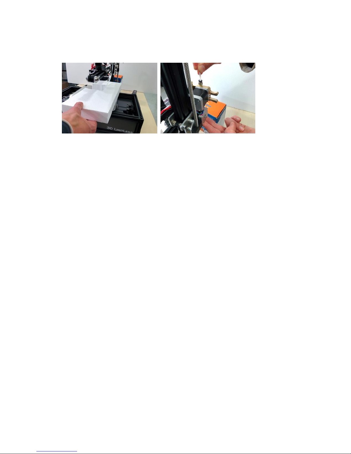
Take off the foam from both sides of the Y spindle. Turn manually the spindle shaft Z
clock wise, holding on to the top and bottom sides until hotend surpasses completely
the support foam
Remove the protective hotend foam from the front side. Lastly, introduce the Teflon
pipe into the extruder fitting until stops
Page 11

5. First look at the Printer 3 ILC
Important characteristics:
The 3D Printer ILC is built to last with
quality materials to ensure continuous
printing accuracy overtime. Therefore it
does not have functional printed parts
and the materials with which it has been
manufactured give it fluid movement.
It has an innovative design for printers of
its kind.
Crane style, lightened structure
Self-leveling system that allows compensating small unevenness that might exist on the printing
surface with the integration of a correction algorithm.
Displacement carriages on the 3 axis are equipped with elements used in robotics to reduce
friction and vibrations this way achieving a very high speed-precision printing ratio
The printing surface with includes a 220v hot plate, controlled by a solid state relay, will allow a
wide variety of printing materials and considerably reduce the waiting time for the start of
printing compared to the ones with 12/24v.
The Bowden tube filament feeding system lightens the print hotend, reducing inertia due to
weight and vibrations that could have an impact on print quality and achieving higher speeds
Page 12
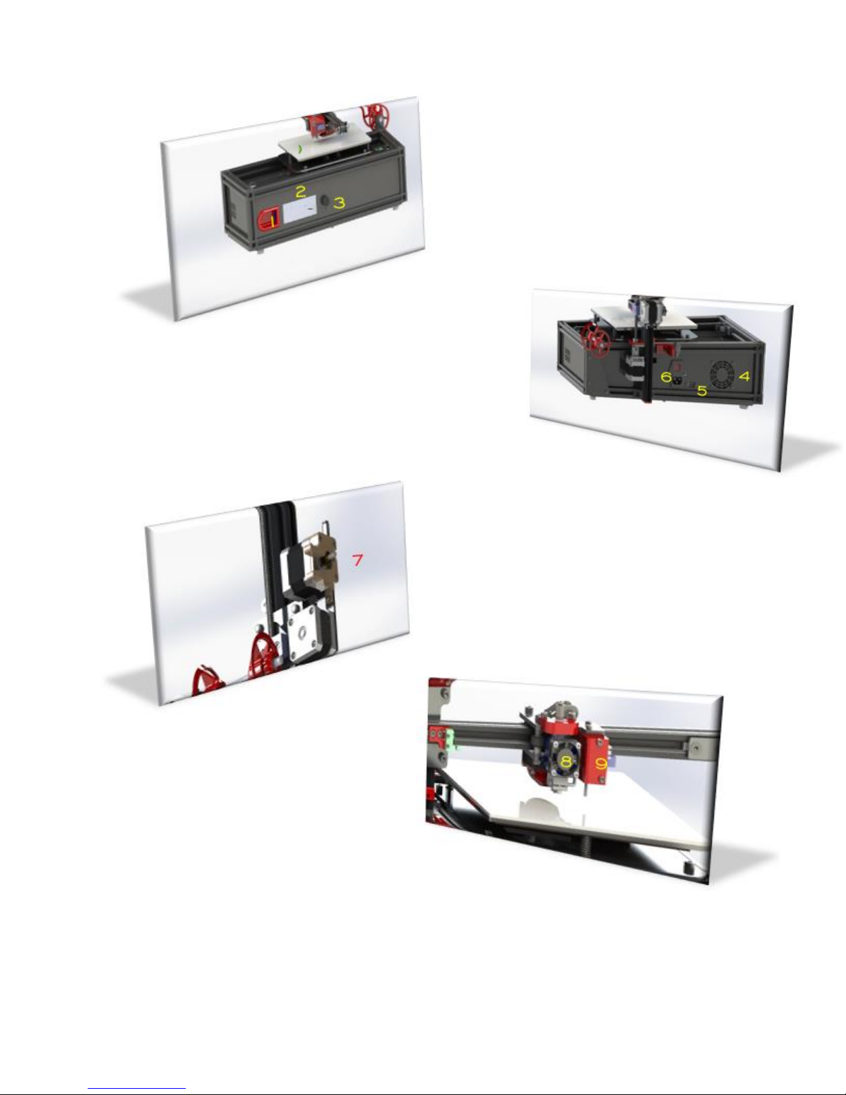
Printer Part description:
BACK
4. Fan
5. USB Connector
6. Power switch
FRONT
1. SD Card Reader
2. LCD Screen
3. Dial
PRINTER HEAD
8. Hotend with fan
9. Box with self-ventilation system
EXTRUDER
7. Drag element with Nema 17 motor
Page 13

5.1 Features and functions
Important printer components and their function
Extruder
This printer uses a Bowden system, as previously said, in which the extruder assembly and the
hotend are not work together to improve performance
Extruder Assembly
Element responsible for dragging the filament consists of:
The Extruder Motor is responsible to power the element that drags the filament to the hotend
Extruder Assembly includes pressure lever, traction spring, toothed and towing pulleys, guiding
the filament and holding elements to the motor
Printer Head
Printer Hotend is in charge of fusing the material to form the layers of the object printed, this
consists of:
Hotend: Element that heats the filament for extrusion, formed by a Heat-Break (calibrated allmetal inner tube), fan, heater block, thermistor and nozzle.
Layer Fan: Element that controls the extruded filament temperature. It includes an axial fan
and a pipe oriented in such a way as to project the air to the hotend nozzle’s outlet and
regulate the filament’s temperature newly finished.
Self-levelling system: It is placed on the hotend and it is responsible for making a map of the
base of the impression by obtaining the height with respect to the origin of the Axis Z in 9
points. Together with the application of a calculating algorithm, provides a system for
correction of possible unevenness on the printed surface.
At the beginning of the print program, a scheduled routine performs the previously cited
process (initial G Code) it’s available in the software included with the device.
Page 14
Printing Base
The surface where the extruded filament is deposited, the printed object will be formed layerby-layer.
It consists of a silicone resistor of 220v and 400w, which provides the right temperature to
perform the printing with different materials. This temperature is transmitted to a 4mm
aluminum surface and is controlled through a solid-state relay and a thermistor. The last
element of this ensemble is a 4mm tempered glass that is in direct contact with the aluminum
surface and it is the base where the material is deposited.
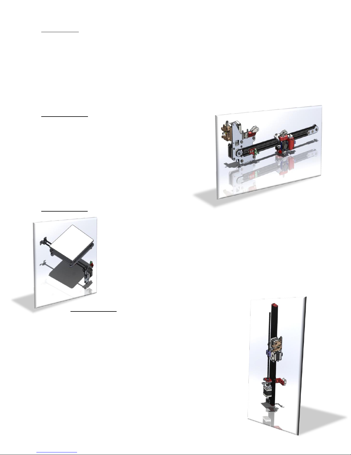
X-Axis Assembly
Allows the hotend movement, it consists of:
An anodized aluminum profile in cantilever.
Sliding carriage with double roller bearing where
the hotend is located.
Toothed belt movement.
Nema 17 Motor.
Limit switch to set the X Axis origin.
Y-Axis Assembly
Allows the printing base movement throughout the Y Axis, it consists of:
Sliding carriage with double roller bearing where the printing
surface is located.
Toothed belt movement.
Nema 17 Motor.
Limit switch to set the Y Axis origin.
Z-Axis Assembly
The Z axis assembly is in charge of elevating the X Axis assembly and
the extruder, giving the height to the object to be printed. It consists of:
An anodized aluminum profile
A displacement car that raises the X-Axis and the extruder
formed by a system of double bearing wheels.
Spindle with flexible coupling and bearing support.
Nema 17 Motor.
Limit switch used in this case as an emergency stop, since this
Axis origin
Is provided by the self-leveling system.
Page 15

6. START UP
The printer will be ready to make the first impression after unpacking, so the 3DLimitless ILC
printer’s surface is leveled, and the offsets (distance between the nozzle and the impression
surface) are configured in the Firmware. As well as having a self-leveling system that can
correct small deviations from the initial adjustments.
Steps to follow for printing the first object:
Assembly of the spool holder:
Place the spool holder formed by the threaded rod with the set of nuts, the two pieces
of the spool holder and the locking nut, elements that come in the packaging. As shown
in the next picture:
Filament charge:
It is necessary for the hotend to be at minimum temperature so the filament can be
charged; otherwise the system will not allow the motor to move. It is recommended to
follow the instructions indicated by the filament manufacturer (information that can be
seen on the filament packaging or on the spool itself).
Access the LCD menu to Prepare by turning the dial to it and click on it. Select the
option Preheat PLA. The temperature will start rising to its target (200 C in the case of
the supplied filament).
Once it has reached its temperature, proceed to introduce the filament, as seen in the
next pictures, through the lower hole of the extruder. Manually push it until it
overpasses the sprocket and hits the Teflon pipe, pressing the extruder lever.
Page 16

Continue pushing the filament through the Teflon pipe till the end.
Using the dial go back to Prepare in the initial menu and turn it until Move Axis, click on
Advance (in this case 1mm) and press again on the dial. Next, the selection of the axis
will appear on the screen and click on the Extruder Field.
The value 0,00 will show, turn the dial clockwise seeing the value increasing while the
extruder drags the filament through the hotend, coming out through the nozzle as seen
on the lower picture. It is recommended to extrude 10mm minimum as soon as the
filament begins to flow through the extrusion nozzle.
CAUTION!! HIGH TEMPERATURE, DO NOT TOUCH ANY PARTS.
Page 17

Preparation of the printing surface
How the material is adhered to the printing surface and more exactly the firsts few layers, it will
be determent to the quality of the end product. To obtain the correct adhesion, follow the next
recommendations:
The tempered glass must be completely clean. To be able to do it, loosen the clamps
from the aluminum base, take out the glass from the printer and clean it (it is
recommended to use soapy water and a clean rag).
Once the glass is clean, dried and put back on the aluminum base, spray a very thin layer
of hairspray on it to help the material stick more easily.
The printer will be ready for the first impression with these two simple steps.
There is an object made from this printer included to prove correct operation after assembly.
Let’s see how to proceed with the first printing:
6.1. Manual Printing from SD Card
The SD card is inserted in the reader after the display, and
the sense of introduction is with the label back and the
gold contacts forward. It is inserted in the reader this way:
to insert or remove the SD card, hold it with the index
finger and the thumb for more comfort. You will not be
able to be inserted upside down as it will not enter into
the reader.
There are a couple of files included in the SD Card: one is a file of the tested piece and
the other is a test piece to determent the ideal temperature point of PLA (temperature
range from 190 C to 210 C, 5 by 5 ºC).
The SD card is already included in the reader, so only the printer will need to be turned
on, access the menu of the LCD’s SD card and choose the print file. For example, the
ship sample piece (BENCHY.GCODE)
Startup routine will begin immediately, by zeroing all axes and performing a leveling
measurement of the printing base, taking the height data in 9 points of the surface, so a
Page 18

map of the printing base is established. An algorithm is programmed to correct any
unevenness that could happen on the hotend.
The printer will start the warm up of the hotend and the extruder after the self-leveling
is performed. Once both temperatures are reached, it will position itself on the center
to start printing.
Options while printing:
We can stop the printing in two ways:
Pause (printing’s temporary stop)
is very useful when you need to
introduce a new fixing element to the
previous model (for example a recessed nut inside
the piece) and then continue printing.
Stop Printing will fully stop the printing process.
Other modifying options are:
Flow Parameters: Filament amount that comes out of nozzle
(measured in percentage).
Printing Speed: You can increase or decrease the speed of the
printing. Keep in mind that increasing the speed could have repercussions
in the quality of the final print.
Ex. shown: The hotend’s (nozzle) and bed’s temperatures, as well as ventilation’s speed (layer
fan).
6.2. Computer Printing
Software installation
- Run with administrator permits “setupRepetierHost_1_6_1” application
included on the CD or download the latest version of:
http://www.repetier.com/download-now
The version must be updated when required (Windows 7, 8, 10). NOTE: The
program requires Microsoft .Net 4 or higher.
Page 19

- Select LANGUAGE.
- Click on CONTINUE to start the installation program.
- Accept the installation agreement of the software manufacture.
Page 20

- Specify the folder where the program will be installed.
-
- Select the options you want to install, Uncheck the option “Repetier-server”
and continue.
- Click Next.
Page 21

- Create an Icon on the desktop.
- Click Next.
- The program will copy the necessary files on your computer.
Page 22
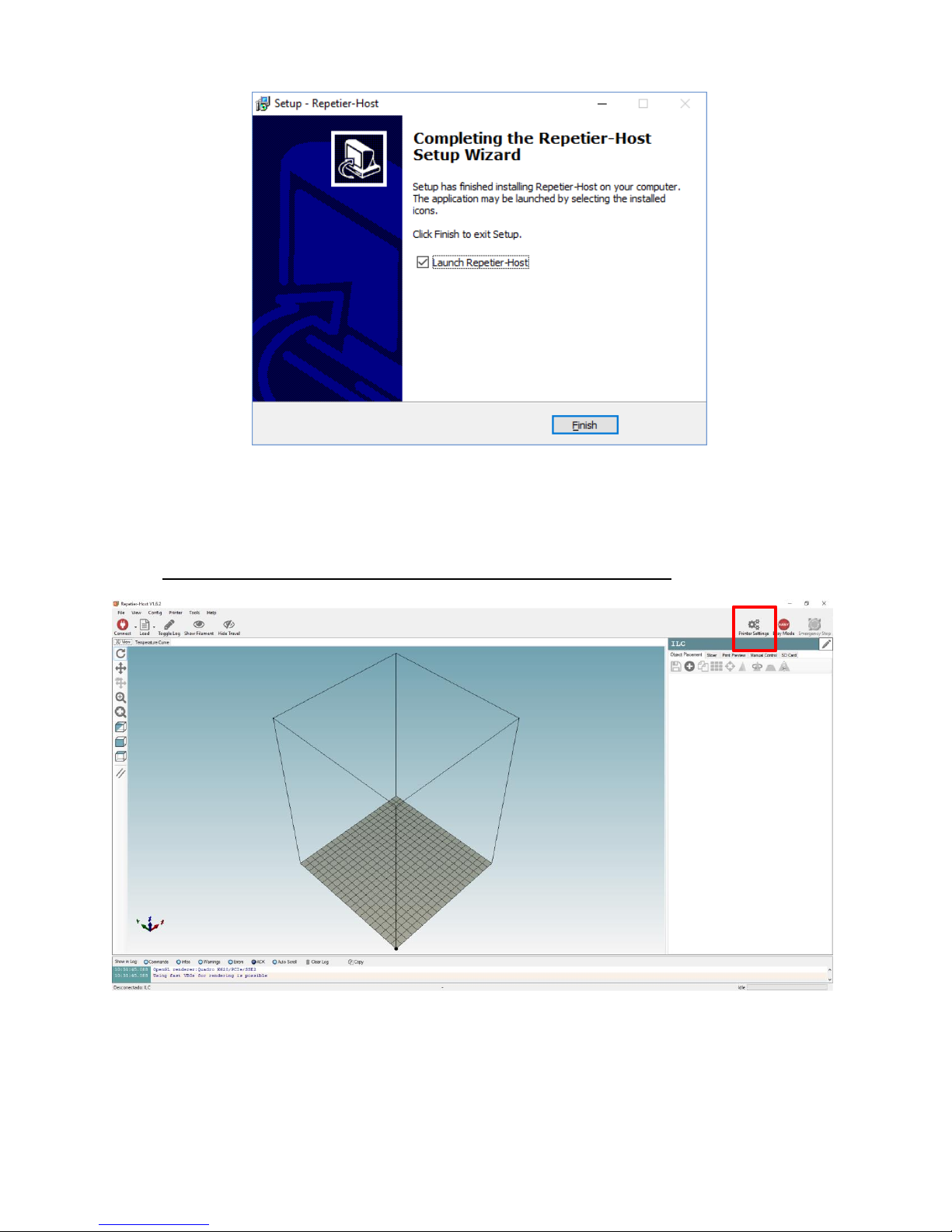
- Once it is finished, click on End and it will open the program directly.
This installation program process is similar to all Microsoft Windows applications. There can be
some differences for Linux and Mac OS systems.
This is the initial screen in the program, a 3D object will appear to demonstrate, that you can
erase. After the first installation you must click the Configure Printer icon.
Page 23

You will enter the following data in the Connecting tab. Make sure to select the right port COM
since it could be different in your computer.
Page 24

On the Printer tab adjust the parameters as shown:
Page 25
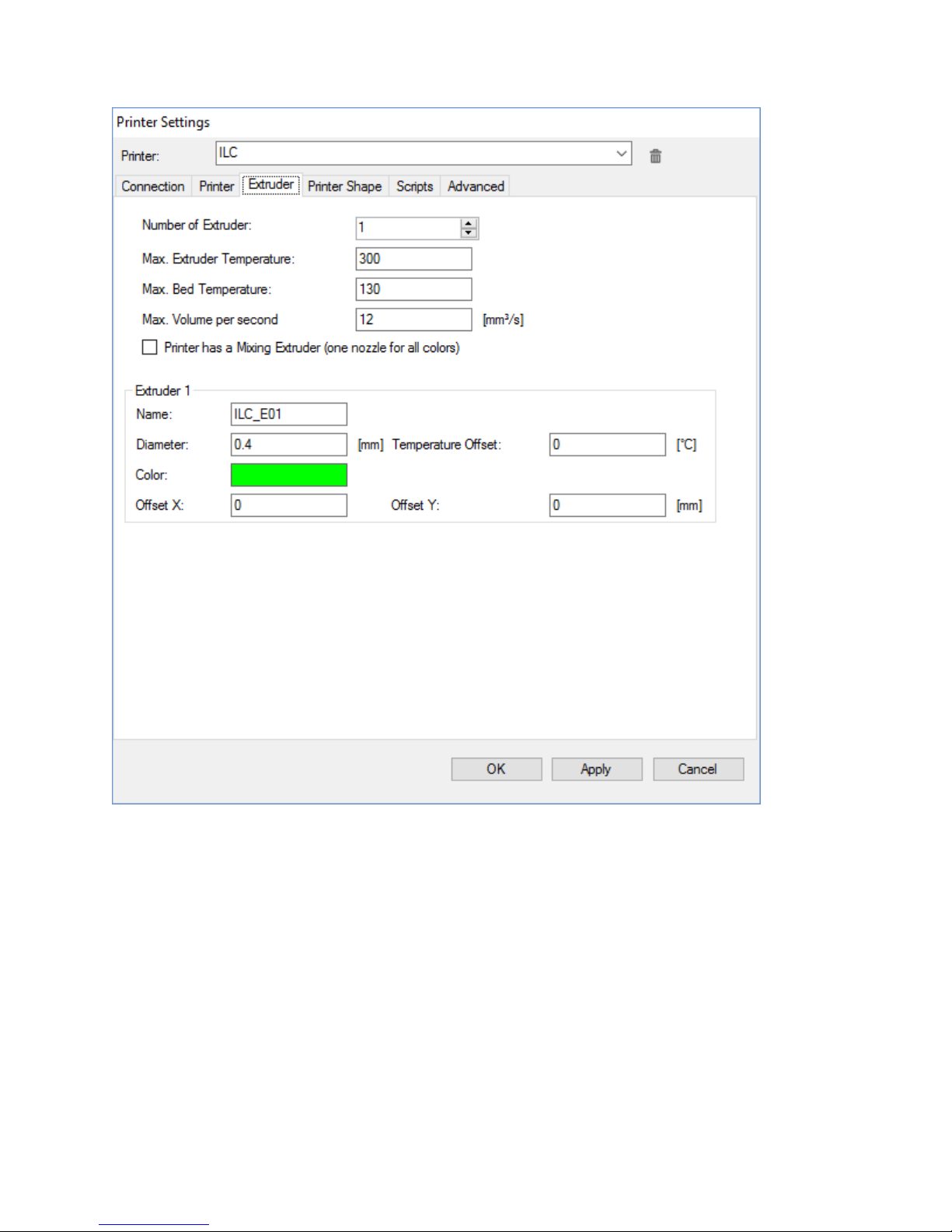
On the Extruder tab adjust the parameters as shown:
Page 26

On the Printer Dimensions tab adjust the parameters as shown:
Note: The parameters dimensions are located on the printer firmware so introducing higher
dimensions will have no effect on the printing surface. In the contrary, lowering the dimensions
of the already specified ones will reduce the printer’s useful surface area. It is recommended
not to modify the printer’s hardware specifications.
The scripts and advanced tabs will be set by default.
Page 27

The working interface consists of several zones:
A 3D display that you can move with the mouse and an option zone (object, slicer, preview,
manual control and SD card) are on the right.
The 3D object display menus are on the left, as well as the tab to CONNECT to the printer and a
FILE to load a 3D file.
You can view at the bottom a log of commands sent to the printer that you can enable or
disable with the top VIEW LOG tab.
There are two possible slicing programs at the SLICER tab (CuraEngine and Slic3r), choose the
one you want.
A 3D model must be separated into layers or slices in order to be printed; this software is in
charge of doing so, processing and sending the code (GCode) to the printer.
CuraEngine is simple to use and the SLICER by default. We recommend starting with this one if
you are a beginner with the 3D printer.
Page 28

Proceed to configure the default CuraEngine parameters by introducing the following
information on each tab, or you can click on the IMPORT tab to transfer all the printing profiles.
You will find them in the CuraEngine file on this CD.
Page 29

Page 30

Page 31

VERY IMPORTANT!!: Introduce the Start and End GCodes as detailed next and make
sure you use them ALWAYS in all jobs, without them the self-leveling and other
operations will not work correctly.
See also the Print Profiles Cura and Slic3r Manual included in this CD.
START
START GCODE SCRIPT
Page 32

VERY IMPORTANT!!: Introduce the Start and End GCodes as detailed next and make
sure you use them ALWAYS in all jobs, without them the self-leveling and other
operations will not work correctly.
See also the Print Profiles Cura and Slic3r Manual included in this CD.
END
END GCODE SCRIPT
Page 33

Press CONNECT to start communication to the printer; if the connection is successful, it will
turn green. Once connected, you can continue on MANUAL CONTROL:
Slic3r is advanced slicer software with more options than CuraEngine, it also allows you to set
your own printing codes. Once you open the program, select from the dropdown the
CONFIGURE tab and a new window will open with Slic3R program:
As done with the CuraEngine program, Slic3R allows you to set the parameters by introducing
the information on each tab, or you can click on the IMPORT tab to transfer all the printing
profiles by going on FILE> LOAD CONFIG BUNDLE and select the corresponding file. The profiles
are in the SLICER PROFILE of the CD provided.
Page 34

Page 35

Page 36

Page 37

Page 38

Page 39

VERY IMPORTANT!!: Introduce the Start and End GCodes as detailed next and make sure
you use them ALWAYS with any job, without them the self-leveling and other operations
will not work correctly.
In Slic3r, Start and End Gcode’s are slight different from the Cura’s gcode, as you can observe.
Page 40

The installation and configuration of the program is done. If you like to experiment with
different values, we recommend setting new Slicer and Filament Profiles.
Page 41

HOW TO WORK WITH REPETIER HOST:
Open the program:
Home Screen:
You can find more functions by going into the Repetier Host manufacturer’s manual.
Download here.
Select FILE which usually comes in the STL format and click on the OBJECT tab at
the right corner of the screen.
Then select the location in your computer or network where your printing file is.
Remember that this should be in any of the compatible formats (refer to the manual). It
will be in our 3DBenchy.stl file.
Once selected, the program will transport and place it in the center of the printing
surface with a preselected orientation. In many cases, it will be necessary to modify the
orientation as well the location depending on the geometry, surface types, refrigeration
needs, etc.
Page 42

After the object is correctly placed, the Repetier program will show the configuration
options. We’ll see each one:
Coping the object
When you click on it, it will ask how many copies are required.
Note: If the copy will be of several different objects, they should be placed inside the
blue square, as shown in the picture.
Page 43

Self-positioning
This option will position the objects in the most optimal space. Let’s look at what
happens when you click on the Self-position tab.
We’ll observe that the objects are placed much closer, optimizing the time of printing by
decreasing the displacements through the printing surface.
Page 44

Center
This option will join together the center of the chosen object with the center of the
printing base.
Page 45

Scale
When you tap on this option a menu will appear:
The scale will be the same on the 3 axis by keeping the lock closed. If what you want is
to scale the axis differently deforming them, you need to tap on the lock.
Note: Scaling can be used to reduce the original size of the objects. For example, by
setting 0.9 would be a 10% reduction equal to 90%. In the contrary a 1.2 would be a 20%
increase corresponding to 120%.
Using the sample at hand we will increase the size by 2.5 equally to 250%, the result is
shown in the next picture:
Page 46

Rotate object
When you go to Rotate option the following menu will appear:
You can rotate positive or negative numbers in 360 degrees on each axis.
Note: You can see the axes orientation by looking at the axes coordinates
representation.
Page 47

You can rotate the object in different ways and forms with the axes orientation as
shown in the sample:
Cut viewer
This option is simply to visualize the internal structure by cutting the object. See the
software’s manual for more details.
Page 48

Mirror
This option will allow you a change of the object’s orientation taking the XY plane
(printing base) as reference, the sample will show the result:
After revising all the different modification options that Repetier offers, you can continue with
the next tab: Slicer.
We will continue with the initial parameters of the sample used previously (Scale, Rotation,
etc.)
Page 49

In this tab you will find the LAYERING options (converting the object into layers). Two layering
motors are integrated in the software, the CuraEngine and Slic3R as part of the Repetier
program (you can get all the details on how to configure them later in this manual).
Let’s see their functions:
The Drop down
It allows you to choose from the two slicing motor options.
Page 50

Slic3R OPTIONS
Cura OPTIONS
This one will allow you to choose the Print
Quality (Print Setting), the Printer (Printer
Settings), and the Filament Configuration
(Extruder I). At the CONFIGURE tab you
must preset the previous adjustable options
which in turn will allow you to see the
program’s as well (refer to the manual).
When you go to the Override Slic3R Settings
you can modify the parameter
configuration (the common ones) without
having to change the preset profile
configuration parameter.
Enable Support will activate the support
placement.
Enable Cooling will activate the layer fan.
Layer Height will set the layer values.
Infill Density will allow establishing the
filling density.
When you go to CuraEngine options you
can select the Printer (Printer
Configuration), Adhesion Type giving you
two options to choose from:
BRIM will create a waste surface attached
to the piece to prevent the printing base
from rising, especially the corners; and
RAFT will create a first layer for the same
reason. Both of them should be removed
and disposed of after printing the object.
Quality tab will define through the layer
height the printing quality.
Support Type will establish the support
options TOUCHING BED and EVERYWHERE,
more detailed explanations on the
CuraEngine manual.
Speed tab will define how quickly the
printing will be between the limits set in the
configuration.
Infill Density, will allow establishing the
filling density.
Extruder 1, will select the Filament
Configuration.
Page 51

You can tap on SLICE with CuraEngine or Slick3R after you defined the slicer motor and its
parameters. The software will start the process in which it will generate the layer and the
GCode necessary to print the object.
The quantity and complexity of the object chosen will determent the amount of time needed
for the process.
As soon as it is finish the program will automatically go to the next tab (Print Preview)
reviewing the print layers:
Page 52

The information you’ll obtain is the following:
Printing Statistics
Estimated Printing Time
Layer Count
Line Count (generated code’s total line number)
Filament Needed (the necessary mm amount for the object)
Display
It allows you to choose the options to preview the object the way it will be done.
Page 53

Show Entirely
Show One Layer
Page 54

Show Range of Layers
Page 55

Once verified the above, click on the PRINT tab and the printing will start by going automatically
to the next tab MANUAL CONTROL where, as explained earlier, you can modify the parameters
while printing.
With the MANUAL CONTROL tab you can use the printer from the application just as the DIAL
and the LCD Screen.
The upper controls will only work when the printer is not operative and they look as shown
next.
You can see if the printer is ON/OFF at the top of the screen.
In the GCode box you can give direct orders to the printer (advanced users only).
In the next box:
You can observe the three axes positions in which the printer is located at the time.
Page 56

You can find the Movement Control. The first one is for the XY Plane.
The empty house icon at the bottom left corner will be used to take all axes back to zero.
VERY IMPORTANT!! When you need to move any axis you must go back to zero (Home)
before so the printer will know where and how much should it move. You should never
move it manually under normal operation conditions.
To move the axis on both directions you need to press on each arrow.
The keys X Y Z will take each axis to HOME (Zero).
The vertical arrows are for the X axis and the horizontal arrows are for the Y axis.
Note: Be aware that the positive direction in the case of the Y is from right to left and of the X
axis is from the back towards the front of the printer.
The Z axis control is located to the right of the previous control.
In the case of the Z axis, Home will be located on the printing surface and its
positive direction corresponds to the increase in quota, meaning elevation
with respect to the printing base.
Page 57

The Extruder is the last control.
With this control you can push the filament with two possible speeds, one faster
than the other.
The retraction however will always perform in the slowest mode.
The rest of the controls are at the bottom of the screen. These are the ones you can
modify while the printing is going on:
Printing Speed starts at 100% and you can increase or decrease it. At higher speed the
quality of printing can be reduced.
Extrusion control can modify the filament quantity that the printer is using, increasing it
when the extrusion is low or reducing it on the contrary.
Ventilation controls the speed of the layer fan for cooling of the extruded material.
Bed Temperature corresponds with the printing surface and it controls its working
temperature.
Extruder 1 is the last control and allows you to control the filament temperature when
exiting nozzle or hotend, adjusting it to each filament.
Page 58

7. Recommendations for proper use and maintenance
Keep the printer clean of debris from materials, especially where the shafts wheels run and
fans.
It can be cleaned with a dry or lightly damp microfiber cloth. When you start cleaning, the
printer’s hot parts must be cold and unplugged from the electrical and USB connections as
well. Plug the printer back on after dry.
The Teflon tube where the extruder filament flows to the hotend must be kept without
folds. If it is removed from the hotend, keep in mind when it is reintroduced that the tube
should go all the way to the bottom (not less than 48mm). This part is very important so to
avoid clogging of the hotend. If the tube is pinched or damaged it must be changed, just as
if the push-fit connectors of both sides are not holding on firmly to the tube.
The cleanliness of the hotend fan must be check frequently since the filament could clog it if
it doesn’t turn as fast as it was established due to dust, debris or obstructions; the hotend
could stop working for lack of cooling. Turn it off when you are cleaning it; you can use
tweezers and small brush. If it’s damaged or it doesn’t turn properly, it must be replaced.
The glass can be clean with dishwashing detergent to remove any debris. In case of
adhesive or material are stuck to it, you can use a glass scraper. Dry it well after that. To
finish it up, you can use a damped microfiber cloth with a little of Isopropyl alcohol to
remove fingerprints or lint that could prevent the proper adhesion of the first layer. In case
the timing belts deteriorate or become loose from using it very frequently, ask the 3D
LimitLess technical support department for replacements.
Keep the vents very clean with a small brush or a regular vacuum cleaner.
The printer should have a yearly maintenance to look for loose screws, bolts or parts. Tight
them up and call the technical support department in case of misalignment or vibrations.
We recommend not leaving any filament in the hotend as well as using a special one for
cleaning and keeping it in perfect condition.
Due to a sealing problem at the tip, melted filament could be coming out between the
hotend trigger and the heating block. Please contact the technical support department.
Usually, the debris clogging the tip or the heating block can be removed by tweezers or
small metal brush while still warm, keeping in mind all the precautions needed not to get
burn.
Page 59

8. PRINTING PROBLEMS
We include some of the most common printing problems and where they come from.
8.1 Lack of Extrusion starting the printing. Common problem among beginners on the
3D printing and it is very easy to resolve.
There are 4 possible causes:
The Extruder has not been purged before printing: It doesn’t
have enough material inside the Hotend due to inertia in the
heating and cooling of it. In the printer software beginning
GCode it has an established routine to purge a 10 mm filament
head before printing that is deposited on one of the surface
corner to prevent this problem.
It is recommended when you are configuring the printing to give a SKIRT to the
object which consists of an exterior parameter separated from the printing
object that will allow you to purge the nozzle and the adhesiveness of the first
layer.
The Nozzle is too close to the printing surface: The Nozzle will clog up if there is
not enough space to deposit the material on the printing surface. It is due to the
Z Axis Offset been too small. The 3DLimitless ILC has preconfigured and tested all
levels. If you want to modify the parameters, you would have to start a new
leveling process to the printing base. You will have to contact our technical
support department and we’ll help you through it.
The Filament has been bitten by the Extruder gear: This happens when the
Extruder pushing gears let out some of the material decreasing the filament
section causing it not having enough contact to keep pushing, the solution is on a
specific chapter of this manual.
Hotend obstruction: If the problem is none of the previous causes then, most
likely the Extruder is clogged up. It could happen when some of the material has
accumulated inside the heatbreak where the temperature is not enough to heat
it up, or after a change of material that requires a higher temperature and not all
remains have been removed from inside the Hotend. To resolve this problem,
you will have to contact our technical support department and we’ll help you
through it since there are many solutions depending on the origin and nature of
used filament.
Page 60

8.2 First layer does not adhere to the printing base.
Another common problem occurs when the first layer (very important) of the printed
object does not adhere correctly and it is coming apart from the printing base.
The Nozzle too far apart from the printing base:
This is the opposite of the lack of Extrusion
starting the printing (8.1). This means, the
filament will not be closed enough to adhere to
the base, because of the nozzle being too far apart
from the printing base. The solution will be
changing the Z Axis Offset’s value for which you
need to do a new leveling process to the printing
base. You will have to contact our technical support department and we’ll help
you through it.
Higher printing speed of first layer: The first layer’s printing speed is usually
slower than the rest of layers. The parameters will be different depending of the
configuration of the Slicer software chosen (SLic3R or CuraEngine). Refer to the
software’s instructions for this case. The recommended value is between 50%
and 70% of the defined speed for the normal printing.
Temperature values and cooling system: When the filament is deposited on the
printing base with a higher temperature difference, it will cool down faster as
well causing it not to adhere correctly. 3DLimitless ILC is equipped with an
electric resistance in the printing surface to add enough temperature and solve
this problem. It is also recommended to use hairspray or PVA glue to the printing
base depending of the material you are using. In the other hand, too much
ventilation at the end of nozzle will have the same effect as before, in this case
you should inhabit the first layer’s cooling function. Refer to the chosen software
instructions.
Brim and Rafts: If the base of the printing object is very small, you should create
a brim around it. It consists of making wings to improve the adherence of the
object avoiding any peeling off from the printing surface.
Another option is a raft that will create a support under the printing object as a
first layer that will not be a part of the end result.
These additions are easily removable after the printing is done.
Page 61

8.3 Lacking Extrusion.
It is a low extrusion because the filament contribution is not enough, it is noticeable that
the perimeters did not join properly and/or material shortages appear in the filling; the
reasons for that are:
Increase Extrusion value: The problem could continue even thou the filament
diameter is properly adjusted. To resolve this, as mentioned previously, you can
change the Extrusion value while the printing is going on or when you are setting
the different filament profiles. Modifying the parameters will depend on which
software you are using and if you are printing manually (with dial and LCD) or
remote printing on the manual control tab of the software.
Incorrect filament diameter configuration: The
3DLimitless ILC printer has an Extruder Assembly for a
1.75 mm filament diameter, for this reason you need
to make sure that this is the value in the software and
each of the filament profiles that you have created. We
recommend measuring the filament at various points
to get an average diameter since filament
manufactures have several tolerances.
8.4 Over Extrusion.
It is the opposite of the previous section and it means
that too much material is deposited mainly on the
upper surface. In this case it will be done in the same
way but in reverse. You will modify the extrusion
coefficient or FLOW by decreasing the extrusion
multiplier value. The way of doing so it will be
different depending on the software you use. Slick3R
will be like a 0.9 equivalent t 90% which is a 10% less
of extruder. CuraEngine will use percentages, i.e. 80%, 90%, etc.
8.5 Holes on the top part of the pieces.
If you can see holes on the top layers of the object while the rest are correct, the
probable causes are:
Fewer upper layers: As you previously saw, some of the
printing parameters to configure before printing are the
number of upper and lower layers. If the value is too low
the problem will occur. We recommend you configure at
least 3 top layers.
Page 62

For example, when you go to CuraEngine settings:
Go to Print/Structures where Top/Bottom Thickness will determent the amount
of upper layers.
To determent the number of layers, you multiply the value of height already
chosen in Quality (0.2 in this case) by the number of layers you want (4 in total in
this case, it will always round it down).
In the case of Slic3R, as soon as you put the number of layers you want it will set
the parameters by itself.
Page 63

When you go to Slicer screen and the Printer Settings:
You will see Horizontal Shells then you’ll find Solid Layers TOP
You will put the desired amount
The infill percentage is too low: When it happens, the upper layers support
surface is small and it will cause the detachment/sinking of them.
Lack of Extrusion: After making sure that the previous ones are not the cause of
the problem; the next possibility could be the lack of extrusion. The solution will
be in the next section.
Page 64

8.6 Detecting fine lines on the pieces
Sometimes when you are printing a hollow object or the deposit of material is spaced
between two points, you can see fine lines. Even thou the lines are easily removable
when the printing has finished, it requires an intervention. The causes for this are:
Value of the filament retraction: When the hotend is
moving with no need of applying any material, the
extruder motor is moving in reverse. You will have to
retract it and trying to avoid deposits of material
where it is not needed.
If the parameter is not correct, the deposit of
material in non wanted places might occur. Using the
Bowden Extrusion system, you will have to introduce a new value (i.e. 4,5mm)
depending on the type of material; you can increase or decrease it to be able to
correct the problem. And optimal retraction value is 1.8 to 2.0 mm.
This is where:
Slic3R
Printer Settings/Extruder tab / Retraction-Length Option:
Page 65

Cura
Cura Tab – Print – Extrusion – Distance Retraction Option:
High Retraction Speed: It could cause bubbles inside nozzle. A regular parameter
would be 40-50mm/sec, keeping in mind that it changes depending on the
material’s hardness you are using. To do so, you will have to go back to the
previous tabs and modify the value on Speed (Slic3R) and on Retraction Speed
(CuraEngine).
High Filament Temperature: If the temperature configuration is not set correctly
and it is too high, the filament becomes very fluid and extrudes without request.
This can be changed in the filament temperature configuration and it can be
done while is printing, as previously explained.
The filament manufacturer will establish the ideal temperature range for the
extrusion.
Page 66

8.7 Excessive heating
You can see some details in the object are not well formed. Probable causes are:
Insufficient Cooling: Most likely the air flow parameters for the
fan are not properly set. This value depends mostly on the
material used. We’ll show you where to do it.
Slic3R
Filament Setting Tab – Cooling Section
You have to set the speed values: minimum, maximum, in bridges and initial
layers; where you don’t wish to use the cooling to promote adherence. The Min
Print Speed parameter will reduce the preset speed value when the printing time
is less than the indicated in “Slow down If Layer Printing Is Bellow”.
Page 67

Cura
Filament Tab – Cooling section
Here you can adjust the minimum and maximum cooling values and the printing
speed in the “Minimum Layer Time” as well, so it will not be less than the
already set.
The cooling percentage value is different from the previously seen and it can
be adjust while printing.
High Printing Temperature: Another possible cause could be a high Extrusion
Printing even when the cooling system is used. If this is the case, you can change
the value on the manual printing or from the software, as previously shown.
High Printing Speed: If the printing speed is very high and the time is too low for
the size of the layer, it might not be enough time for this to cool down and when
the next hot filament is deposited over it, it can cause a deformation in the layer.
“Slow down If Layer Printing Is Bellow” and “Minimum Layer Time” are the
parameters to use to adjust the min printing time of each layer. See Cooling
Deficiency section.
Printing few objects at the same time could be another solution, this way the
printing time used for one layer is higher as well as the cooling time.
Page 68

8.8 Marks on the top side
This happens when you see grooves in the filling of the upper faces. The possible causes
are:
Slic3R and “Z HOP” in CuraEngine where you can lift the Hotend during the
traveling without extrusion, going back to the original position when it is
necessary to continue the extrusion.
Slic3R
Printer Settings Tab - Extruder 1 – Option: Retraction - Lift Z
Very High Extrusion Flow: Please refer to the 8.4 Over
Extrusion. The effect of the hotend’s heat while moving
over the already printed layers. If the displacement
strategy is done inside the same layer and the filling comes
out irregularly, geometrically speaking, the hotend can
travel through the already printed surface leaving marks
on it because the heat effect. To avoid it, go to “LIFT Z” in
Page 69

Cura
Print Tab – Extrusion - Z Hop
8.9 Layers Sliding
Some sliding could happen of the X/Y Axes while printing. The possible causes are:
Slic3R
Print Settings Tab – Speed – Speed for Non-Print Moves – Travel
High Hotend Speed: If a high travel speed is set up without
extrusion, it is recommended to lower it to 70%.
Page 70

Cura
Print Tab – Speed and Quality – Travel
Page 71

Mechanical or Electronic Problems: The step-by-step adjustments of the motor
controls which could have an incorrect current setting. In the case of the X/Y
Axes, it may also be due to an excess or strain on the belts. If this is the case,
please contact our technical support department.
Note: All our printers have been individually tested with particular emphasis
on this point, among others.
8.10 Clogged Nozzle
This happens when you see the filament is not coming out of nozzle when the extrusion
is being done. The possible causes are:
The Filament temperature is too Low: It happens sometimes when you change
one type of filament for another (i.e. ABS to PLA), with the first one having a
higher melting point and you perform the initial purge to clean the hotend of
debris from previous material, you need to set the temperature closer to the ABS
melting point than the PLA’s otherwise it could form a plug in the Heatbreak. Do
not exceed the max temperature recommended by the filament manufacturer or
it could create crystallized debris in the Heatbreak and Tip.
Deformed Filament End: It can happen after the printing is finished or a long
retraction due to cooling conditions. In this case, pull out the filament from the
Heatbreak, cut a 2-3 cm piece and reintroduce.
If the problem continues after trying these options, the Heatbreak is blocked with
filament. Please contact our technical support to help you.
8.11 Plastic Bubbles in the Piece
There are bubbles on the exterior perimeters of the object. Possible causes are:
Printing Temporary Stops: It usually happens when you are
printing directly from the PC and there are communication
failures from the PC to the Printer due to background
programs, PC’s limited resources, memory, etc. Try to free the
PC as much as possible of activity both, memory and
microprocessor. It could also be an error of the PC’s USB Port
connected to the printer, try changing it. Much data is sent in
real time from the PC while printing is going on, so you should
prioritize the printing activity.
degrees at the time until the problem stops.
Excessive Temperature: The filament becomes very fluid when
the temperature is too high and it will come out of nozzle even
when it is making displacements in non-extrusion zones. You
will need to decrease the extrusion temperature gradually 5
Page 72

8.12 Spaces in the Top Layer between Perimeters and Filling
There is a lack of material at the joining of the filling with the top layer perimeters. The
possible causes are:
Lack of Overlap between Filling and Perimeters: An overlap is always needed
between the layers so the union of the two parts occurs, for this matter you have
the INFILL OVERLAP Tab.
Slic3R
Print Settings Tab – Advance – Overlap Infill/Perimeters Overlap
Page 73

Cura
Print Tab – Extrusion – Infill Overlap
Printing Speed of the Upper layers is too High: If this happens the upper layers
will not adhere properly. You will need to configure it and reduce this value until
you reach a solution to the problem.
Slic3R
Print Settings Tab – Speed for Print Moves – Top Solid Infill
Page 74

Cura
This option does not exist when using other algorithms.
8.13 Warping
100 C). This is the reason why you should add hairspray when printing with this
material.
It usually happens when you print with ABS
and other materials. It is a deformation with a
slight lifting of the corners due to the lack of
adhesion of the first layer.
Lack of Fixative (Hairspray): With ABS is
required to use another fixation or adherent
besides a very hot printing surface (more than
In addition to that, the use of the BRIM option is also recommended. It consists
of adding wings around the perimeter of the object to be printed to reduce the
possibility of getting stuck to each other, as well as generating small circles
around the corners of the object so that they don’t lift up in few layers. (pg. 79)
Page 75

Slic3R
Print Settings Tab – Skirt and Brim – Brim Width
Cura
Print Tab – Structure – Skirt and Brim – Brim Width Parameter, this value will
define the wing size.
When using CuraEngine it will be necessary adding the BRIM option on the left
corner of the SLICER Dropdown. See in detail.
Page 76

Air drafts: We recommend to keep the printer away from air drafts since many
of the materials used, especially ABS, are very sensitive to temperature changes.
8.14 Layers Gap
You can see there are holes between the layers for lack of union among them. The
possible causes are:
Cover Height: You have to keep in mind the
nozzle diameter you are using when you are
setting the cover height since if this one is
higher, the layers will not stick together. As a
general rule, you should establish the maximum
height as 20% less than the nozzle diameter.
I.E.: if you use the 3D-ILC’s 0.4 mm nozzle, the
layer’s maximum height will be 0.32 mm. Nozzle
can be substituted with a higher or lower
diameter depending of the printing needs.
Page 77

Low Extrusion Temperature: If the extrusion temperature is configured too low,
the cooling down will happen rapidly and the upper layer will not adhere to the
previous one, even if the filament reaches a high temperature.
For that reason keep always in mind the temperature range as the filament
manufacture suggests.
Excess of Ventilation: Printing materials as ABS, Nylon, etc.., are very sensitive to
a quick cooling of the layers creating delamination and poor adherence between
them and possible warping mentioned earlier is aggravated. We recommend
turning off or reducing to the minimum the layer fan to resolve the problem, it
can be done manually or in the filament profile, and this way you will get longer
cooling time and more homogeneous.
You can download different filament profiles with the optimum parameters from
our web page so you can print without these problems.
8.15 Split Filament
out an amount of filament greater than the actual output capacity of the nozzle
section. Verify the installed nozzle parameters.
A decrease of the filament section is observed
because the extruder motor moves forward while
the filament does not advance so the dragging gear
“bites” it. The possible causes are:
Miss-configured Nozzle: If the diameter of the nozzle
configured in the Slicer software is higher than the
Hotend nozzle installed, the dragging system will give
Page 78

Cura
Slic3R
Printer Settings Tab – Extruder – Size – Nozzle Diameter
You will have to go to the Repetier Host configurations to get all the values. To
verify them go to Printer Settings Tab (top right side) – Extruder – Diameter
Extrusion Temperature too Low: It will cause the extrusion flow to be lower and
it will be harder to come out of the nozzle exerting a counter pressure that
prevents the extrusion giving the “bite” effect on the filament. We recommend
Page 79

increasing the temperature between the ranges already established by the
filament manufacturer.
Printing Speed too high: High speed printing could have the same effect
described before due to the same causes. We recommend lowering the speed
parameters until the “bite” effect disappears. It can happen as well with the
combination of low temperature and high speed. If you wish to keep high speeds
you must slightly raise the melting temperature.
Clogged Hotend: filament is not coming out of the hotend nozzle. Stop the
printing and follow instructions as of 8.10 section. Check all the parts of the
printing: Extruder, Teflon Tube, Heatbreak, Nozzle, Speeds, and Temperature.
Page 80

9. Proper Product Disposal
(It means electrical and electronic equipment waste. Applicable in the European Union and in
the European Countries with selective waste collection systems)
If you see this symbol on the product, accessories, or any informative material that
come with the equipment, it indicates that at the end of its useful life neither the
product nor the electronic accessories (Extruder, cables, etc…) should be disposed
of with other domestic waste.
Please recycle correctly and separate from all other waste to avoid possible health and
environmental issues. In this way it promotes the sustainable reuse of material.
Contact the distributor of this product or relevant local authorities to inform you about how
and where it can be subjected to ecological and safe recycling.
Page 81

10. Informative Links
You can find great resources in these links many of them Open Source and for free.
http://www.thingiverse.com
https://www.youmagine.com
https://grabcad.com
http://www.turbosquid.com
https://sketchfab.com
http://www.123dapp.com/Gallery/content/all
https://3dwarehouse.sketchup.com/index.html
https://pinshape.com/
We also propose a series of links to 3D design and modeling applications, most of them are
free:
Autodesk
Sketchup
Thinkercad
Freecad
Blender
Rhino
SolidWorks
Catia
3DBuilder
The original file included in the SD: 3DBenchy.STL, it comes from:
http://www.thingiverse.com/thing:763622
Repetier-Host is license of Hot-World GMBH & Co. KG, Slick3R is license of Alessandro
Ranellucci, Cura and CuraEngine are license of UltiMaker B.V.
The different operative systems mentioned in this manual are respectively license of: Microsoft
Corporation, Apple Inc, and Linux Foundation.
The links provided are license of their respective manufacturer.
Page 82

11. Warranty
Warranty Time Period
The warranty will start when you make your purchase (invoice or delivery date).
Warranty time is up to 12 months. Elements are subject to wear and tear are not
covered by this warranty.
Warranty time will not be extended or renewed, nor will it be affected otherwise due to
the subsequent resale, repair, or product exchange. In case of product repair or
exchange during this time, they will be covered until the end of the warranty or 6
months, whichever comes first.
Warranty will be invalid in case of incurring any of the assumptions included in
“Warranty Exclusions”.
Warranty Management
In case of product defect, proceed as follows:
1. Notify our Technical Support Chanel (soporte@3dlimitless.com) of any defect or
incidence within the first month of detecting any, never after the warranty time
period.
2. Have available proof of purchase with at least the date, serial and model
numbers.
3. The product must be sent or taken to the original purchase place or to the 3D
Limitless address, at buyer’s expense. After inspecting the problem, if it is not
within the assumptions of the “Warranty Exclusions”, 3D limitless will take care
of returning the product to the costumer free of charge; in the case of being one
of them, we will repair the machine at a cost; budget sent to costumer’s for
approval.
4. The performance criteria will be exclusively determined by 3D Limitless.
5. This criterion will be as follows: repairing, element’s replacement, or complete
product exchange.
6. Defective or replaced elements will be 3D Limitless property.
7. The buyer will receive a detail report of the incident and actions taken once the
warranty management is finished.
Warranty Exclusions
The next cases are not under warranty:
1. The normal wear-and-tear of the product including, without limitations, mobile
parts wear, control panels and elements that interact with the product’s
operation.
2. Damage caused by misuse or neglect when using the product.
Page 83

3. Damage caused by: accidents, fires, liquids, chemical products, other substances,
floods, vibrations, excessive heat, inadequate ventilation, voltage outage,
incorrect or excessive voltage, radiation, electrostatic discharge including
lightning and other external forces or impacts.
4. Deterioration caused by improper transportation and handling like using
different packaging from the one provided, including the element’s protection
(Expanded polystyrene).
5. Repairs or attempts of repairs done by third parties not by 3D Limitless.
6. Modifications done to the product to adapt to rules and safety regulations of
particular countries, outside of what the design or manufacture was produced
for, are not covered.
7. Warranty covers the product hardware components, not software or firmware
other than that provided by 3D Limitless.
Limitations and Disclaimers
This warranty is valid and current in the country where the product was bought and
restricted to the countries in the European Economic Union (EEU).
This warranty is the only and exclusive guaranty before 3D Limitless and the unique and
exclusive responsibility of 3D Limitless to the defects of its products. Therefore this
warranty will substitute any other issued by 3D Limitless oral, written or legal (not
mandatory).
With the exception of the previously mentioned cases, 3D Limitless will not give other
warranties (explicit, implicit, statutory or others) related to the product, the software
quality or its annexes, operation, accuracy, reliability or adaptability of the logic
equipment or any other. If this exception is not tendered or contemplated by the
current laws, 3D Limitless will limit or exclude the warranty only to the extent of these
laws. Any warranty that cannot be completely excluded shall be limited to the duration
of this. This warranty will not exclude or limit any legal rights (mandatory) under the
applicable national law or any of its rights against the vendor.
3D Limitless is not responsible for: damages or loss of product, services, this warranty or
others, including economic loss or invaluable damages; benefits, income or information
losses; use of this product or associated ones or loss of it or indirect, accidental or
critical damages.
3DLimitless will not be responsible for any wrong installation or improper use of this
product as explained in this manual.
It will not be our responsibility if the maintenance of the product is not done as
recommended in the manual.
Page 84

3DLimitless will not be responsible for the wrong installation or use of this product that
does not respect the technical or safety rules of the country where it was installed
and/or used.
Consumers have legal rights (statuary) under the national laws in relation to the
consumer products. This warranty will not affect their statuary rights, nor the nonexcludable, nor limitable, nor the rights of the person from whom this product was
purchased. You can assert your rights as you see fit.
Page 85

12. CE Conformity Declaration
3D Limitless Sociedad Limitada
Calle Falperra, 55
15007 A Coruña (España)
VAT ID: ESB70490149
www.3DLimitLess.com
info@3DLimitLess.com
It Declares:
Product: 3D Printer
Model: ILC
Manufacturer: 3D LimitLess
Made in: Spain
Meets all the rules and regulations on the 2006/42/CE norm,
Complying with the harmonized standards:
UNE EN ISO 12100:2012
UNE EN 13849-1:2008
EN 60204-1:3007
The technical documentation is deposited in the address of the manufacturer’s
headquarters.
A Coruña, Spain. March 2016
Marcos Souto Fernández
Co-Founder 3D LimitLess
Page 86

Address:
C/ Falperra, 55 bajo
15007 A Coruña
Spain
Contact:
www.3DLimitLess.com
Http://www.facebook.com/3dlimitless
Twitter: @3dlimitless
info@3dlimitless.com
3D LIMITLESS
Welcome to a Revolution with No Limits!
 Loading...