

Page 1
the world‘s best designers united
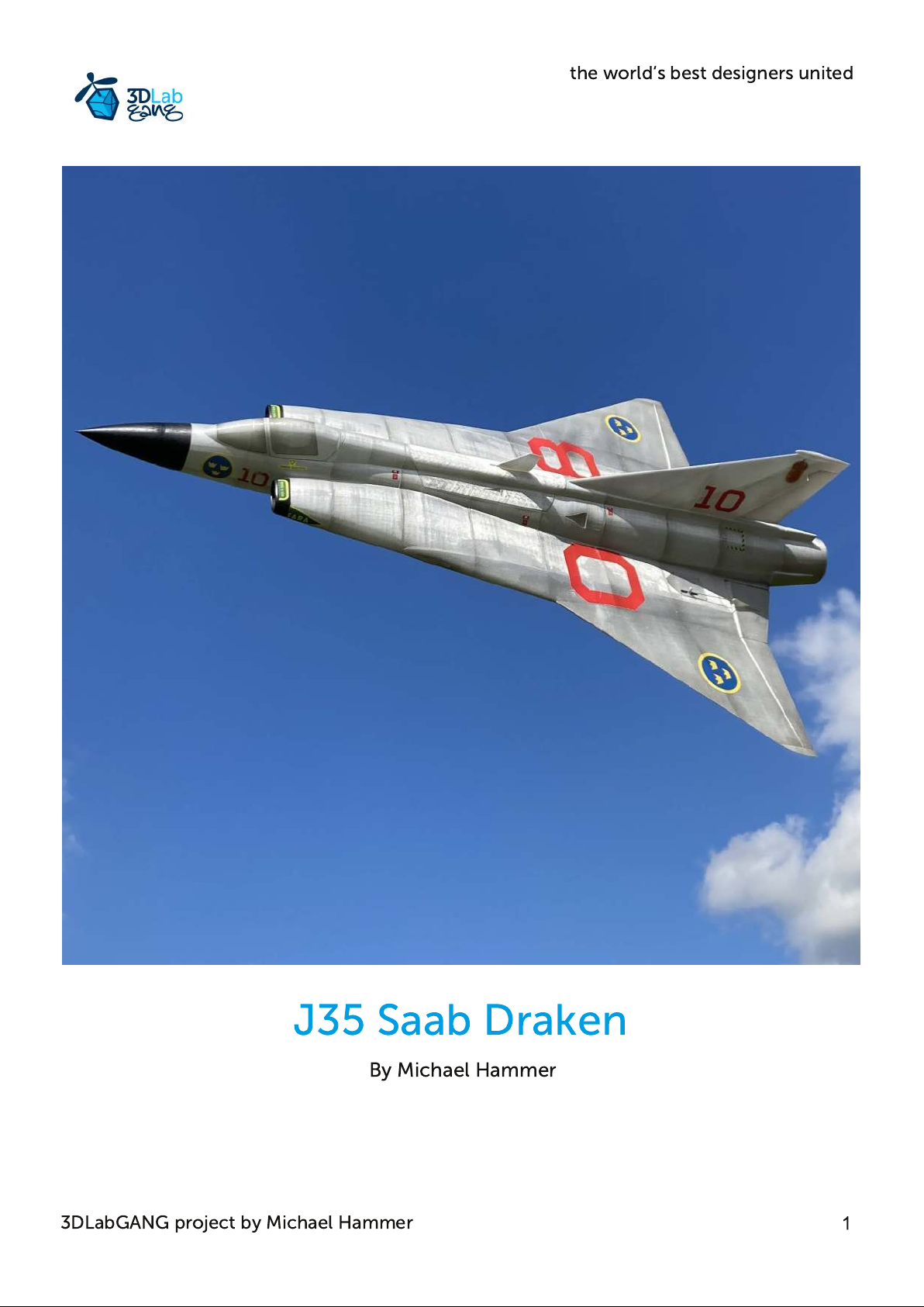
J35 Saab Draken
By Michael Hammer
3DLabGANG project by Michael Hammer
Page 2
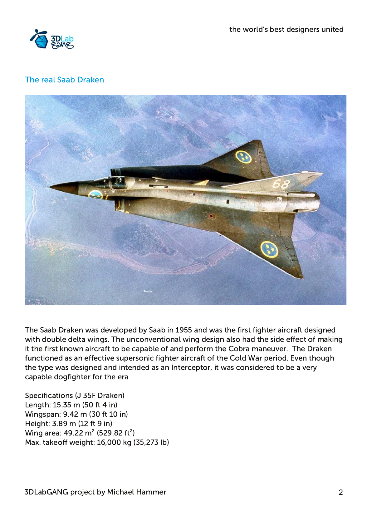
The real Saab Draken
the world‘s best designers united
The Saab Draken was developed by Saab in 1955 and was the first fighter aircraft designed
with double delta wings. The unconventional wing design also had the side effect of making
it the first known aircraft to be capable of and perform the Cobra maneuver. The Draken
functioned as an effective supersonic fighter aircraft of the Cold War period. Even though
the type was designed and intended as an Interceptor, it was considered to be a very
capable dogfighter for the era
Specifications (J 35F Draken)
Length: 15.35 m (50 ft 4 in)
Wingspan: 9.42 m (30 ft 10 in)
Height: 3.89 m (12 ft 9 in)
Wing area: 49.22 m² (529.82 ft²)
Max. takeoff weight: 16,000 kg (35,273 lb)
3DLabGANG project by Michael Hammer
Page 3
the world‘s best designers united
The J 35 Saab Draken semi scale model
The 3D printed Saab Draken is designed to look and fly like the full size Draken. The lines
and proportions of the model match the real jet with its elegant double delta wing and
leading edge air intakes.
The optimized edf duct ensures great performance without the use of cheater holes or non
scale sized air intakes. Designed to be powered by a 50mm FMS electric ducted fan (4S
version) and a 4S2200mAh Lipo battery, the model has great performance and flight times
from 6-8 minutes. The model is designed to be printed from regular PLA or PolyAir 1.0. I
highly recommend using PolyAir 1.0 from 3DLabPrint because of its very good layer
adhesion.
The model is very strong and resilient to damage. The model requires no carbon tubes or
similar reinforcements. Just print the parts and glue them together with cyano glue. The
Saab Draken model is designed to be powered by a FMS 50mm EDF and a 4S2200mAh
quality battery. Only two servos are needed as the model is controlled by elevons - just like
the real Draken.
The model also features a large hatch for easy access to the battery and EDF. The hatch has
a hidden locking mechanism that is triggered by moving the dorsal antenna forward.
The model comes with a control throw gauge for easy adjusting of the correct movement of
the elevons. The battery tray is spring loaded and can be positioned in three different
positions making it easy to balance the model correctly at the Center of Gravity
The Saab Draken is designed with an optional catapult hook for safe and consistent bungee
assisted launch. The model can be hand launched but it is recommended to use a catapult
or bungee with 7-8 kg pulling force for a safe launch of the model.
All parts are designed to be easily aligned and glued with cyano glue.
Model specifications
Wingspan: 730mm
Length: 1092mm
Wing Area: 21,6dm²
Wing Loading: 53g/dm²
Airfoil: Eppler E180 modified
Ready to fly weight (4S2200mAh): 1150g
FMS EDF max thrust: 650 g
Thrust to weight ratio: 0,57
3DLabGANG project by Michael Hammer
Page 4
the world‘s best designers united
Bill of Materials
1mm pianowire
Spring from ball point pen
Cyano hinge sheet
Cyano glue and accelerator spray, medium or thin
2 x HTX900 servoes or similar 9g servos
EDF: FMS 50mm 4S edition available at Aliexpress.com
Receiver: 4-6 ch
ESC: 40A
Battery: 4S2200mAh 25C or higher
3D Printer Requirements
Recommended Prusa MK3S : 250 x 210 x 210 mm, minimum diagonal for wing chord is 297
mm
Nozzle: 0,4mm
Filament: PLA or PolyAir 1.0
Slicing software: Simplify3D
Print settings
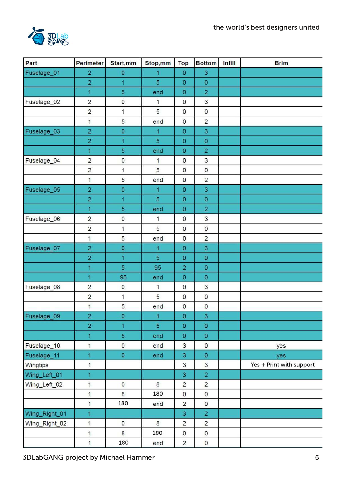
All parts are designed to be printed with 0,4mm nozzle, 0,25mm layer height
Before you start slicing the stl-files yourself, I highly recommend printing the supplied G-
Code files first to see if they will print OK on your printer. For many the supplied G-Code
files will do the job just fine. But if you need to slice the stl-files, you can find info in the table
on how best to slice them. A lot of parts are listed with different settings for for different
height intevals. The Simplify 3D slicer with its advanced function with multiple processes
dependent on the z-axis height will handle these settings well.
If using a Slicer which can not handle multiple processes, just print the part with bottom
layers and no top layers. A hot knife or Dremel can be used to remove any unwanted part
when the print is finished.
3DLabGANG project by Michael Hammer
Page 5
the world‘s best designers united
3DLabGANG project by Michael Hammer
Page 6
the world‘s best designers united
Important
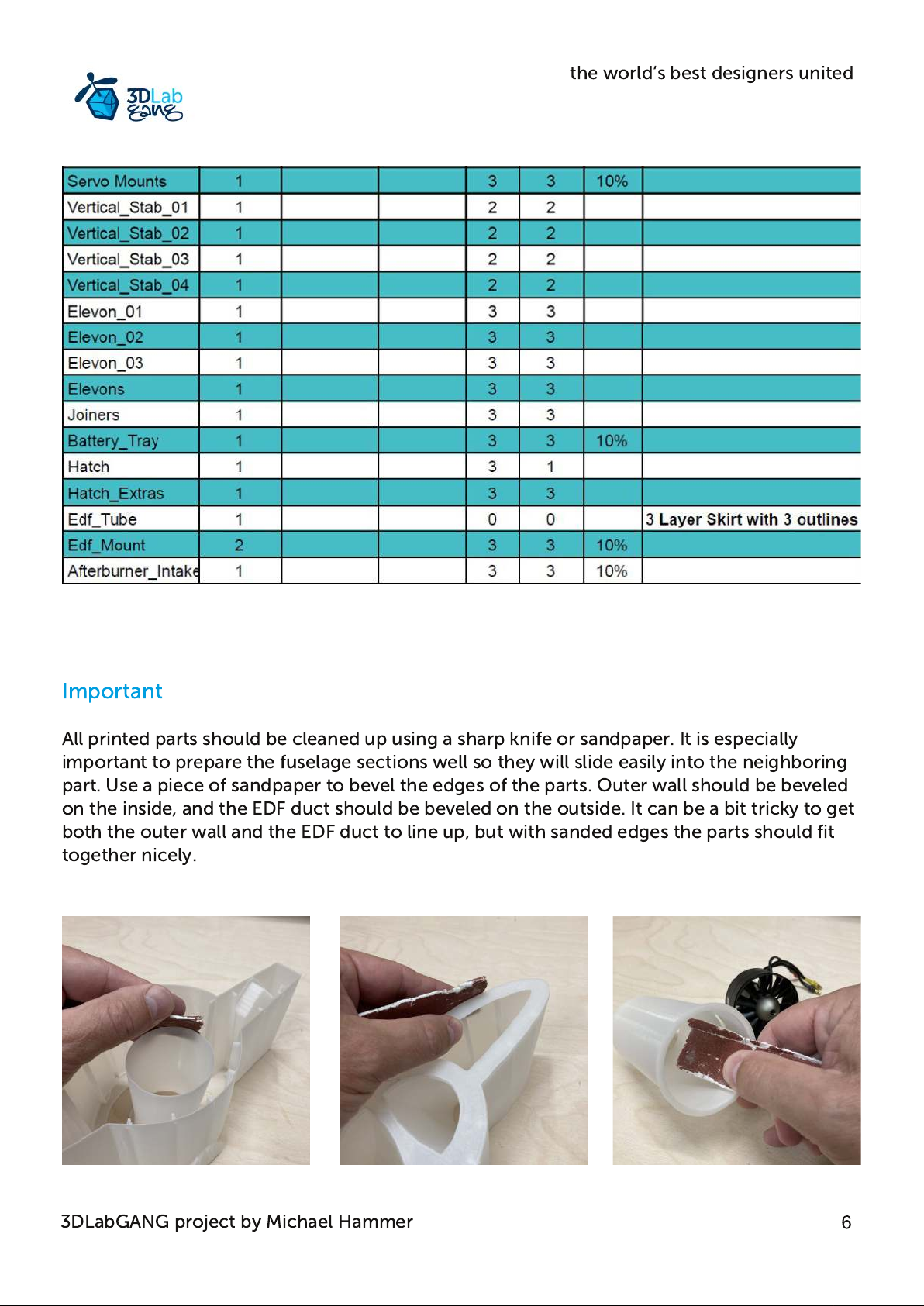
All printed parts should be cleaned up using a sharp knife or sandpaper. It is especially
important to prepare the fuselage sections well so they will slide easily into the neighboring
part. Use a piece of sandpaper to bevel the edges of the parts. Outer wall should be beveled
on the inside, and the EDF duct should be beveled on the outside. It can be a bit tricky to get
both the outer wall and the EDF duct to line up, but with sanded edges the parts should fit
together nicely.
3DLabGANG project by Michael Hammer
Page 7
Fuselage Assembly
the world‘s best designers united
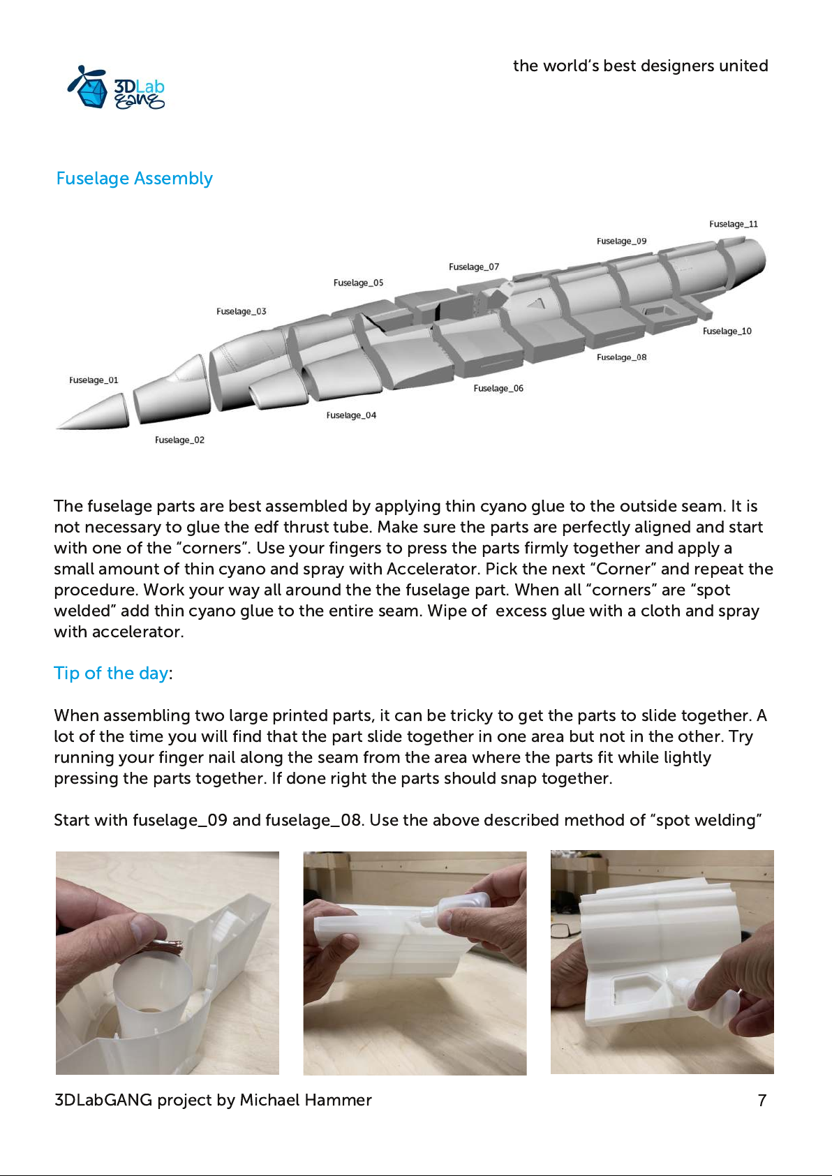
The fuselage parts are best assembled by applying thin cyano glue to the outside seam. It is
not necessary to glue the edf thrust tube. Make sure the parts are perfectly aligned and start
with one of the “corners”. Use your fingers to press the parts firmly together and apply a
small amount of thin cyano and spray with Accelerator. Pick the next “Corner” and repeat the
procedure. Work your way all around the the fuselage part. When all “corners” are “spot
welded” add thin cyano glue to the entire seam. Wipe of excess glue with a cloth and spray
with accelerator.
Tip of the day:
When assembling two large printed parts, it can be tricky to get the parts to slide together. A
lot of the time you will find that the part slide together in one area but not in the other. Try
running your finger nail along the seam from the area where the parts fit while lightly
pressing the parts together. If done right the parts should snap together.
Start with fuselage_09 and fuselage_08. Use the above described method of “spot welding”
3DLabGANG project by Michael Hammer
Page 8
the world‘s best designers united
Continue with fuselage_07. Route the servo extension wires through Fuselage_07 and fit in
together with Fuselage_09 and 08. Take your time getting the parts lined up perfectly
before adding any glue.
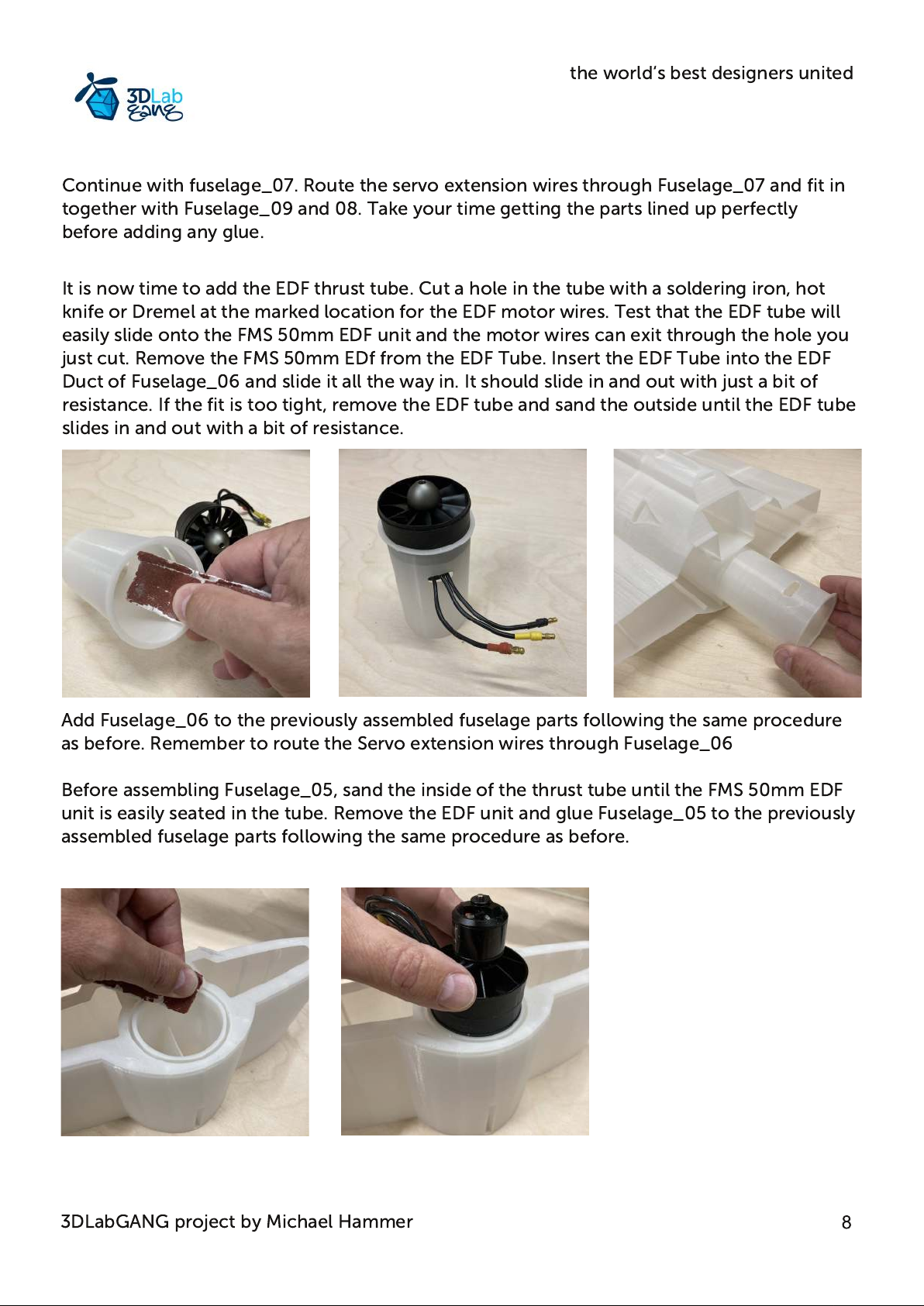
It is now time to add the EDF thrust tube. Cut a hole in the tube with a soldering iron, hot
knife or Dremel at the marked location for the EDF motor wires. Test that the EDF tube will
easily slide onto the FMS 50mm EDF unit and the motor wires can exit through the hole you
just cut. Remove the FMS 50mm EDf from the EDF Tube. Insert the EDF Tube into the EDF
Duct of Fuselage_06 and slide it all the way in. It should slide in and out with just a bit of
resistance. If the fit is too tight, remove the EDF tube and sand the outside until the EDF tube
slides in and out with a bit of resistance.
Add Fuselage_06 to the previously assembled fuselage parts following the same procedure
as before. Remember to route the Servo extension wires through Fuselage_06
Before assembling Fuselage_05, sand the inside of the thrust tube until the FMS 50mm EDF
unit is easily seated in the tube. Remove the EDF unit and glue Fuselage_05 to the previously
assembled fuselage parts following the same procedure as before.
3DLabGANG project by Michael Hammer
Page 9
the world‘s best designers united
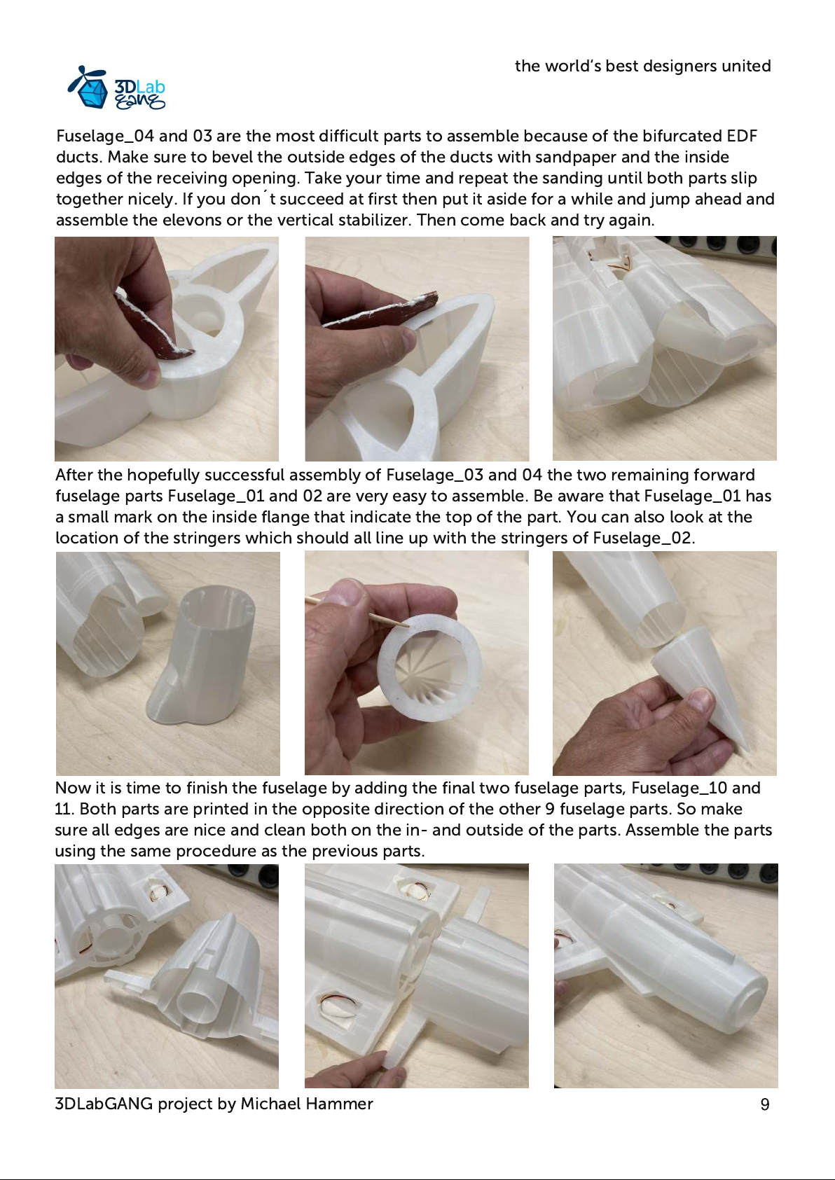
Fuselage_04 and 03 are the most difficult parts to assemble because of the bifurcated EDF
ducts. Make sure to bevel the outside edges of the ducts with sandpaper and the inside
edges of the receiving opening. Take your time and repeat the sanding until both parts slip
together nicely. If you don´ t succeed at first then put it aside for a while and jump ahead and
assemble the elevons or the vertical stabilizer. Then come back and try again.
After the hopefully successful assembly of Fuselage_03 and 04 the two remaining forward
fuselage parts Fuselage_01 and 02 are very easy to assemble. Be aware that Fuselage_01 has
a small mark on the inside flange that indicate the top of the part. You can also look at the
location of the stringers which should all line up with the stringers of Fuselage_02.
Now it is time to finish the fuselage by adding the final two fuselage parts, Fuselage_10 and
11. Both parts are printed in the opposite direction of the other 9 fuselage parts. So make
sure all edges are nice and clean both on the in- and outside of the parts. Assemble the parts
using the same procedure as the previous parts.
3DLabGANG project by Michael Hammer
Page 10
the world‘s best designers united
Hatch Assembly
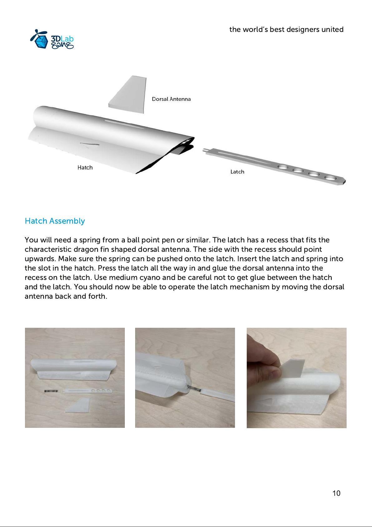
You will need a spring from a ball point pen or similar. The latch has a recess that fits the
characteristic dragon fin shaped dorsal antenna. The side with the recess should point
upwards. Make sure the spring can be pushed onto the latch. Insert the latch and spring into
the slot in the hatch. Press the latch all the way in and glue the dorsal antenna into the
recess on the latch. Use medium cyano and be careful not to get glue between the hatch
and the latch. You should now be able to operate the latch mechanism by moving the dorsal
antenna back and forth.
Page 11
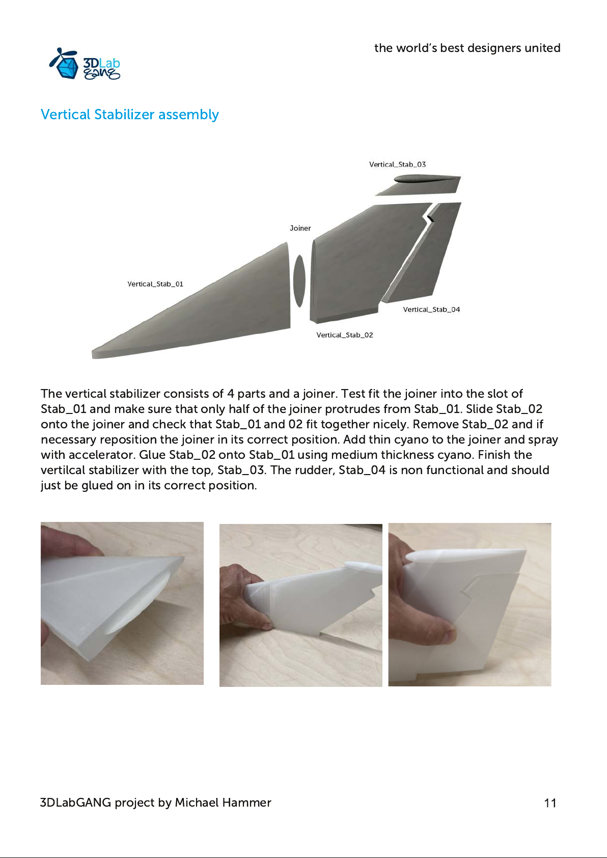
The vertical stabilizer consists of 4 parts and a joiner. Test fit the joiner into the slot of
Stab_01 and make sure that only half of the joiner protrudes from Stab_01. Slide Stab_02
onto the joiner and check that Stab_01 and 02 fit together nicely. Remove Stab_02 and if
necessary reposition the joiner in its correct position. Add thin cyano to the joiner and spray
with accelerator. Glue Stab_02 onto Stab_01 using medium thickness cyano. Finish the
vertilcal stabilizer with the top, Stab_03. The rudder, Stab_04 is non functional and should
just be glued on in its correct position.
Vertical Stabilizer assembly
the world‘s best designers united
3DLabGANG project by Michael Hammer
Page 12
the world‘s best designers united
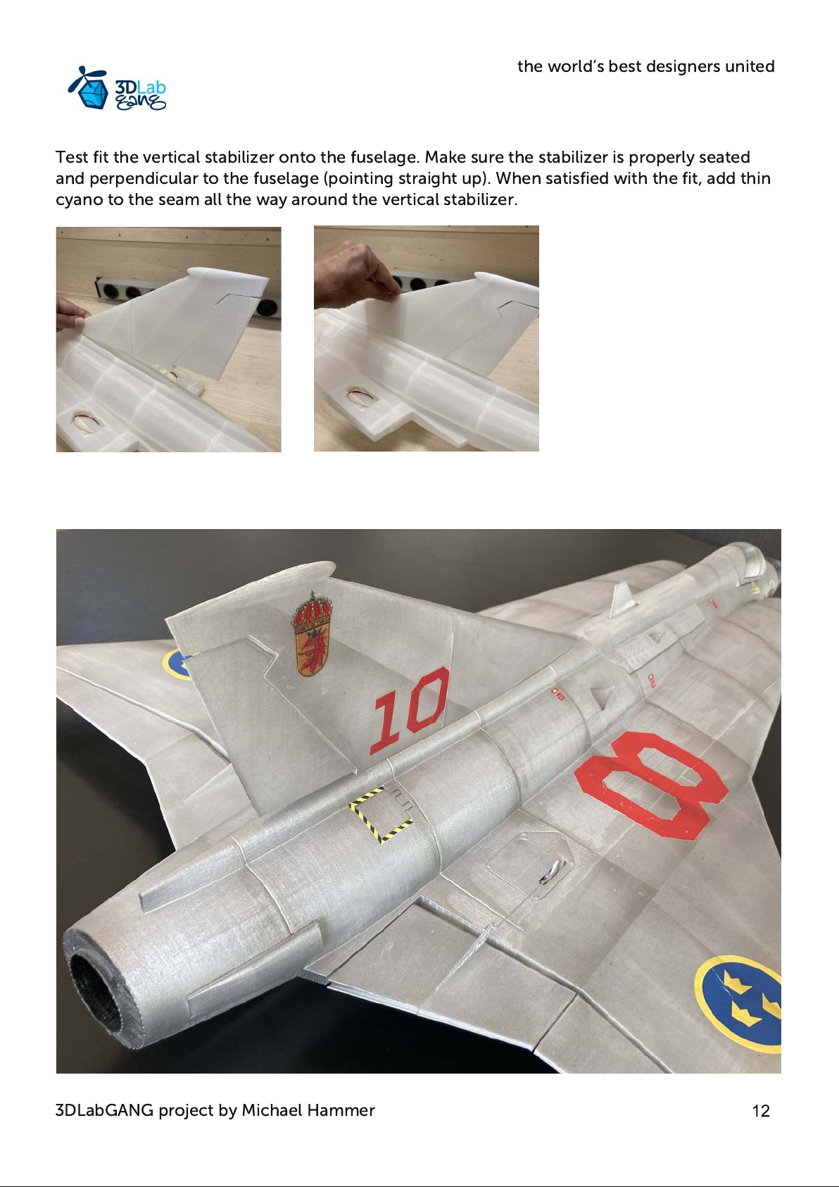
Test fit the vertical stabilizer onto the fuselage. Make sure the stabilizer is properly seated
and perpendicular to the fuselage (pointing straight up). When satisfied with the fit, add thin
cyano to the seam all the way around the vertical stabilizer.
3DLabGANG project by Michael Hammer
Page 13
the world‘s best designers united
Wing Assembly
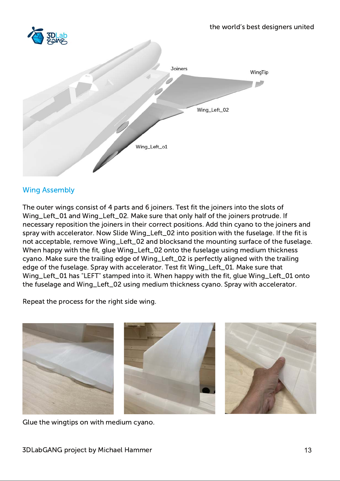
The outer wings consist of 4 parts and 6 joiners. Test fit the joiners into the slots of
Wing_Left_01 and Wing_Left_02. Make sure that only half of the joiners protrude. If
necessary reposition the joiners in their correct positions. Add thin cyano to the joiners and
spray with accelerator. Now Slide Wing_Left_02 into position with the fuselage. If the fit is
not acceptable, remove Wing_Left_02 and blocksand the mounting surface of the fuselage.
When happy with the fit, glue Wing_Left_02 onto the fuselage using medium thickness
cyano. Make sure the trailing edge of Wing_Left_02 is perfectly aligned with the trailing
edge of the fuselage. Spray with accelerator. Test fit Wing_Left_01. Make sure that
Wing_Left_01 has "LEFT" stamped into it. When happy with the fit, glue Wing_Left_01 onto
the fuselage and Wing_Left_02 using medium thickness cyano. Spray with accelerator.
Repeat the process for the right side wing.
Glue the wingtips on with medium cyano.
3DLabGANG project by Michael Hammer
Page 14
the world‘s best designers united
Elevons assembly
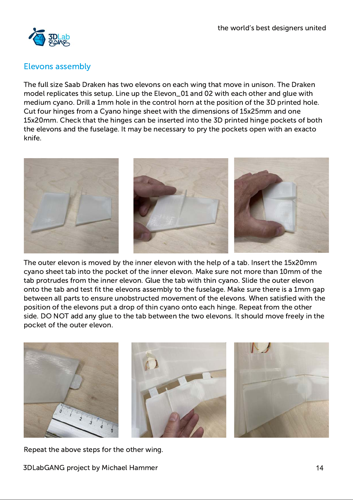
The full size Saab Draken has two elevons on each wing that move in unison. The Draken
model replicates this setup. Line up the Elevon_01 and 02 with each other and glue with
medium cyano. Drill a 1mm hole in the control horn at the position of the 3D printed hole.
Cut four hinges from a Cyano hinge sheet with the dimensions of 15x25mm and one
15x20mm. Check that the hinges can be inserted into the 3D printed hinge pockets of both
the elevons and the fuselage. It may be necessary to pry the pockets open with an exacto
knife.
The outer elevon is moved by the inner elevon with the help of a tab. Insert the 15x20mm
cyano sheet tab into the pocket of the inner elevon. Make sure not more than 10mm of the
tab protrudes from the inner elevon. Glue the tab with thin cyano. Slide the outer elevon
onto the tab and test fit the elevons assembly to the fuselage. Make sure there is a 1mm gap
between all parts to ensure unobstructed movement of the elevons. When satisfied with the
position of the elevons put a drop of thin cyano onto each hinge. Repeat from the other
side. DO NOT add any glue to the tab between the two elevons. It should move freely in the
pocket of the outer elevon.
Repeat the above steps for the other wing.
3DLabGANG project by Michael Hammer
Page 15
the world‘s best designers united
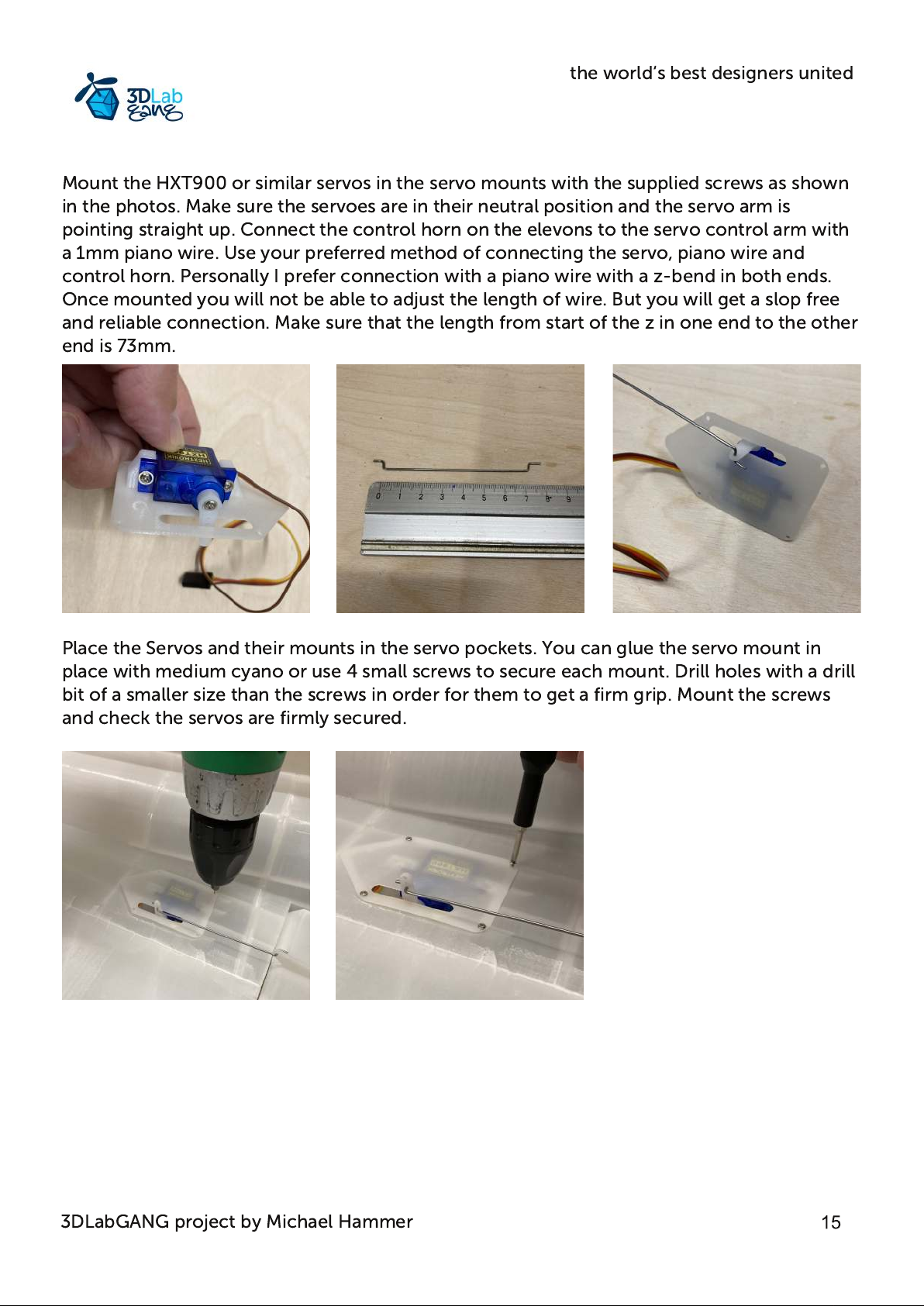
Mount the HXT900 or similar servos in the servo mounts with the supplied screws as shown
in the photos. Make sure the servoes are in their neutral position and the servo arm is
pointing straight up. Connect the control horn on the elevons to the servo control arm with
a 1mm piano wire. Use your preferred method of connecting the servo, piano wire and
control horn. Personally I prefer connection with a piano wire with a z-bend in both ends.
Once mounted you will not be able to adjust the length of wire. But you will get a slop free
and reliable connection. Make sure that the length from start of the z in one end to the other
end is 73mm.
Place the Servos and their mounts in the servo pockets. You can glue the servo mount in
place with medium cyano or use 4 small screws to secure each mount. Drill holes with a drill
bit of a smaller size than the screws in order for them to get a firm grip. Mount the screws
and check the servos are firmly secured.
3DLabGANG project by Michael Hammer
Page 16
the world‘s best designers united
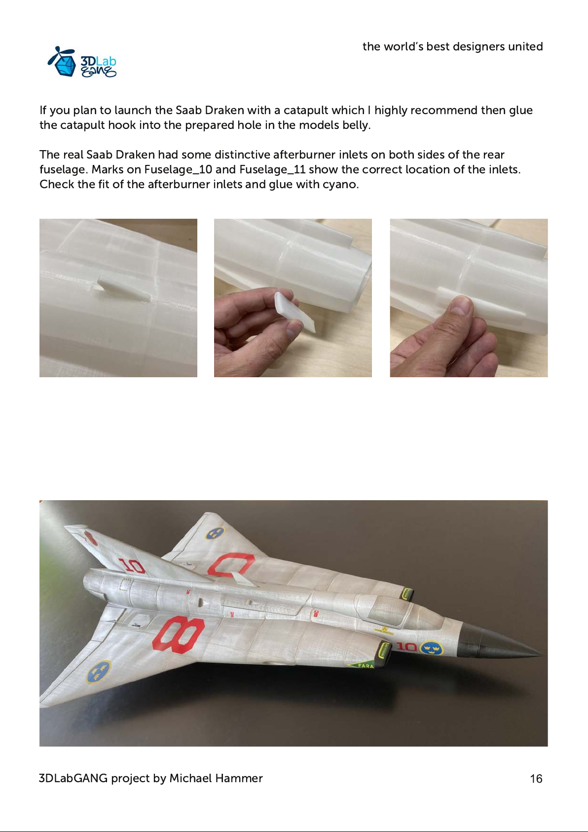
If you plan to launch the Saab Draken with a catapult which I highly recommend then glue
the catapult hook into the prepared hole in the models belly.
The real Saab Draken had some distinctive afterburner inlets on both sides of the rear
fuselage. Marks on Fuselage_10 and Fuselage_11 show the correct location of the inlets.
Check the fit of the afterburner inlets and glue with cyano.
3DLabGANG project by Michael Hammer
Page 17
the world‘s best designers united
EDF Assembly
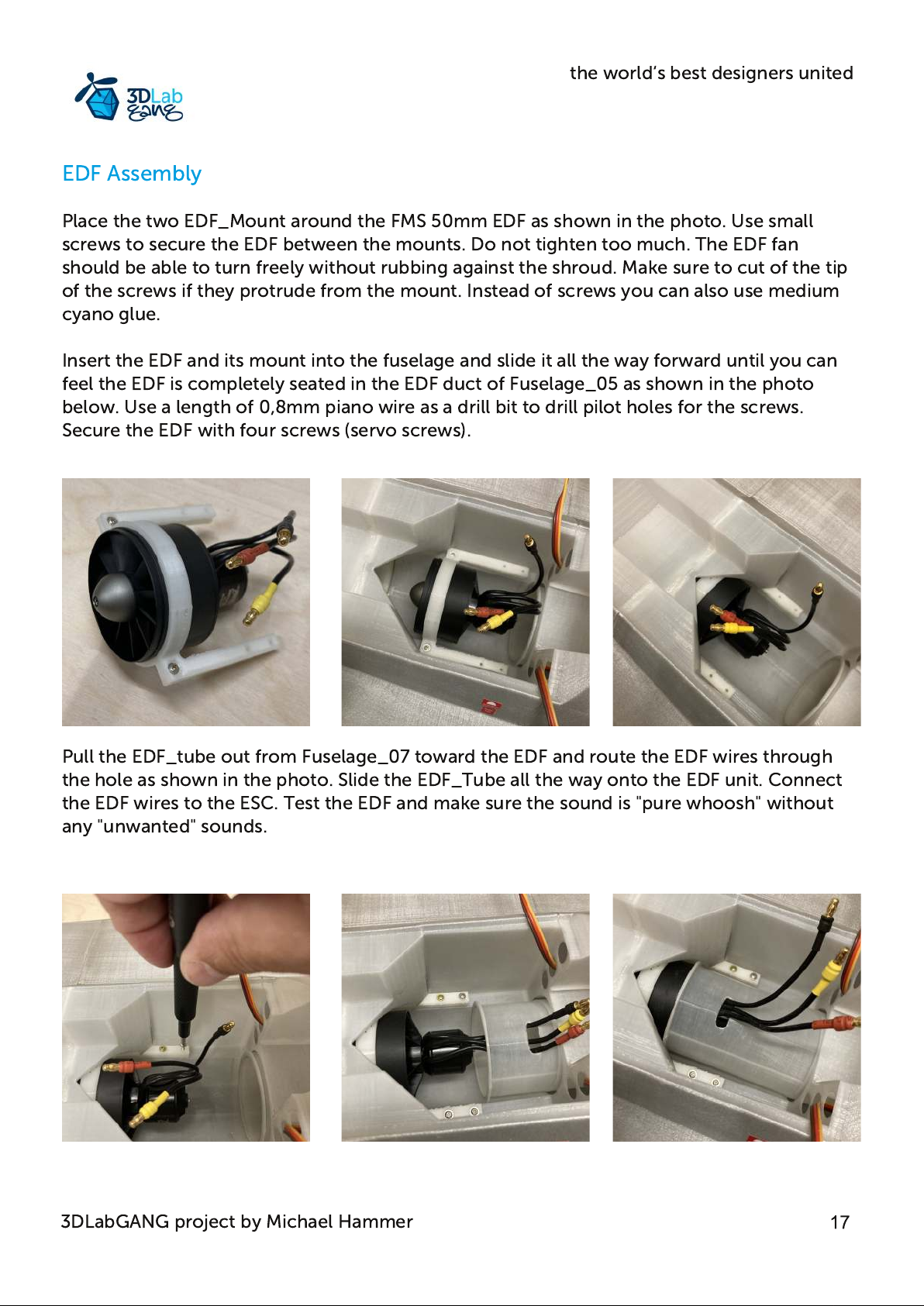
Place the two EDF_Mount around the FMS 50mm EDF as shown in the photo. Use small
screws to secure the EDF between the mounts. Do not tighten too much. The EDF fan
should be able to turn freely without rubbing against the shroud. Make sure to cut of the tip
of the screws if they protrude from the mount. Instead of screws you can also use medium
cyano glue.
Insert the EDF and its mount into the fuselage and slide it all the way forward until you can
feel the EDF is completely seated in the EDF duct of Fuselage_05 as shown in the photo
below. Use a length of 0,8mm piano wire as a drill bit to drill pilot holes for the screws.
Secure the EDF with four screws (servo screws).
Pull the EDF_tube out from Fuselage_07 toward the EDF and route the EDF wires through
the hole as shown in the photo. Slide the EDF_Tube all the way onto the EDF unit. Connect
the EDF wires to the ESC. Test the EDF and make sure the sound is "pure whoosh" without
any "unwanted" sounds.
3DLabGANG project by Michael Hammer
Page 18
the world‘s best designers united
Battery positioning
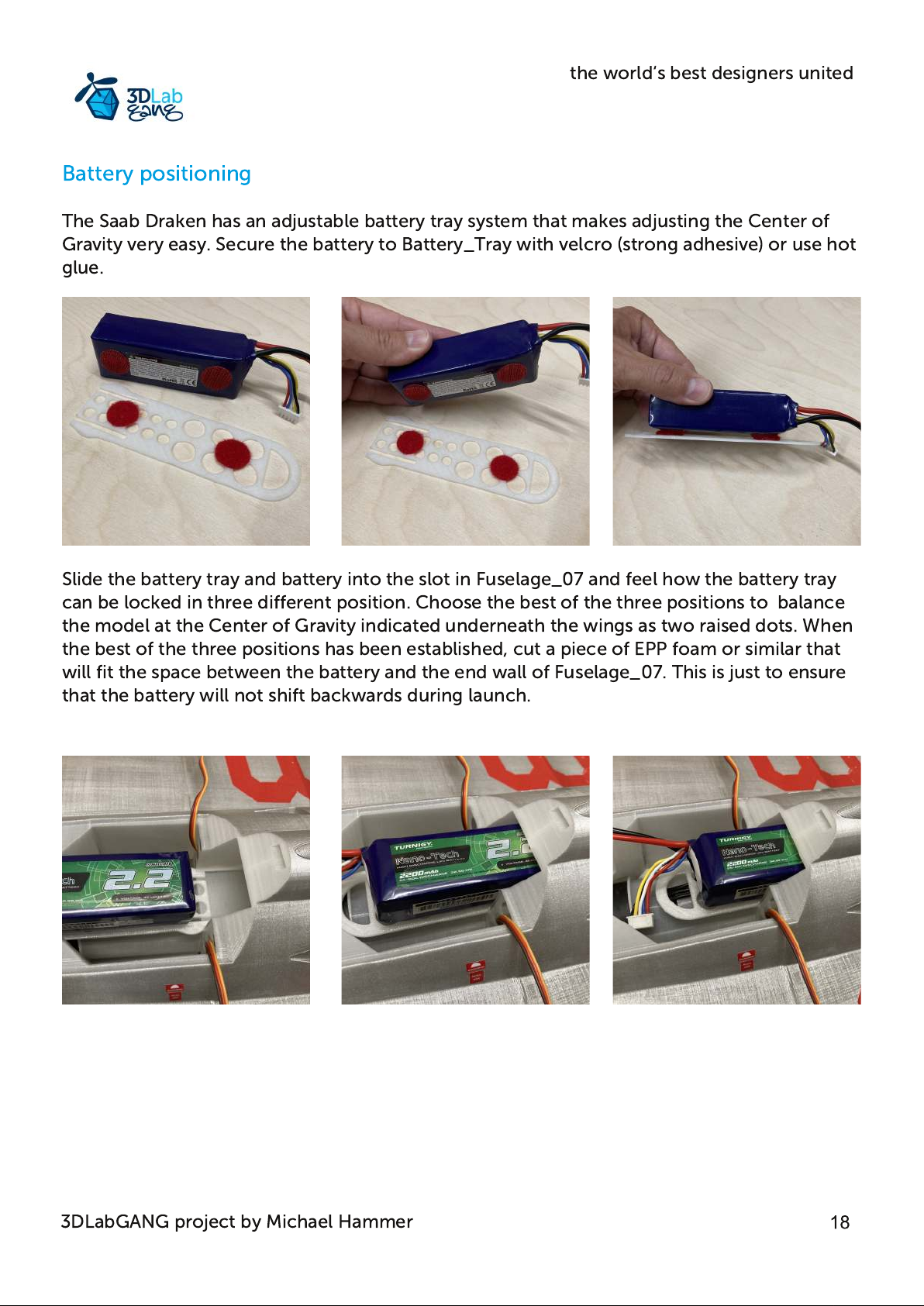
The Saab Draken has an adjustable battery tray system that makes adjusting the Center of
Gravity very easy. Secure the battery to Battery_Tray with velcro (strong adhesive) or use hot
glue.
Slide the battery tray and battery into the slot in Fuselage_07 and feel how the battery tray
can be locked in three different position. Choose the best of the three positions to balance
the model at the Center of Gravity indicated underneath the wings as two raised dots. When
the best of the three positions has been established, cut a piece of EPP foam or similar that
will fit the space between the battery and the end wall of Fuselage_07. This is just to ensure
that the battery will not shift backwards during launch.
3DLabGANG project by Michael Hammer
Page 19
the world‘s best designers united
Control Throw Adjustment
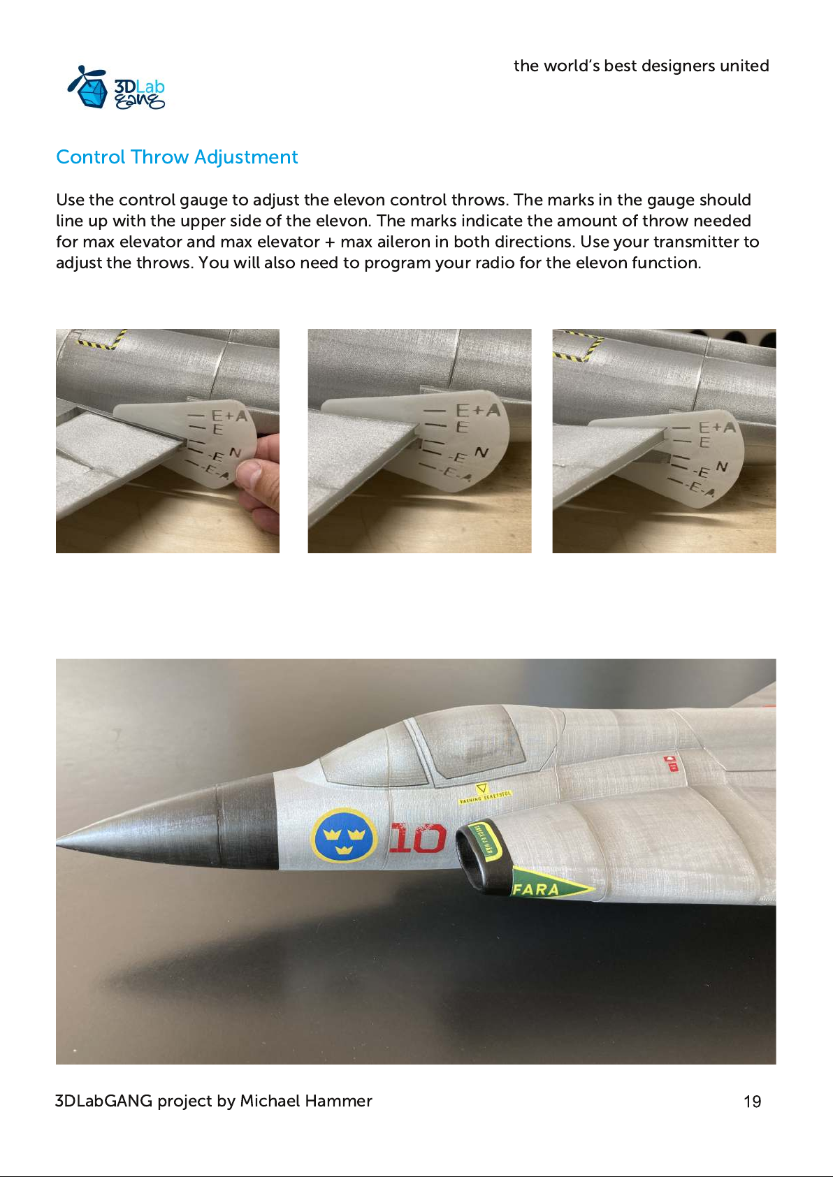
Use the control gauge to adjust the elevon control throws. The marks in the gauge should
line up with the upper side of the elevon. The marks indicate the amount of throw needed
for max elevator and max elevator + max aileron in both directions. Use your transmitter to
adjust the throws. You will also need to program your radio for the elevon function.
3DLabGANG project by Michael Hammer
Page 20
the world‘s best designers united
Center of Gravity
Before first flight make sure the model will balance at the Center of Gravity, CG which is
indicated underneath the wings as two raised dots. If you lift the ready to fly model it should
balance at the CG marks. If the model does not balance at the CG marks move the battery
forward or backwards until the model balances at the CG mark.
First flight
Always remember: It is the airflow across the wings that creates lift. Keep the airspeed up at
all times.
The J35 Saab Draken model flies much like a real jetfighter. Speed should be kept up at all
times and flying is all about energy management. Energy will bleed quickly if for example
very tight turns are performed resulting in slow speed and in worst cases, a stall. If the
Draken model is flown in a scale like manner with gentle maneuvers and enough speed, the
model will fly "Like on Rails" with no bad habbits at all. Make sure your place of flying has
plenty of open space as the Draken will cover a lot of distance in a short period of time.
It is highly recommended to use a catapult/bungee system to launch the J35 Saab Draken
model. A catapult/bungee system will launch the model in a predictable way with plenty
airspeed at a nice angle. And it will do it again and again. Check out this Youtube video:
about building a simple yet very reliable catapult system: https://youtu.be/ASX42mwIAyA
The Draken should be launched with a pull of 6-7 kg and at a 5-10 degree upward angle.
The J35 Saab Draken can be hand launched but the succes of it depends on the person
throwing it and the method used. Never try to throw and control the model yourself. Get
someone with experience in hand launching to throw the model. Do not run with the model
before the throw. It never adds any extra speed and most of the time it messes up the throw.
The Saab Draken has been tested with a variety of launch methods and you will get the best
results with an underhand throw and assisted push at the tail. Grab the model with your
secondary hand just after the hatch and place your primary hand on the exhaust tube.
Throw the model in a 10-15 degree upward angle and try to accerate the model by pushing
at the exhaust. Be careful not to push the tail down or up but push it straight ahead. Add full
power to the EDF just before the launch. After the launch keep the wings level and fly
straight until speed builds up. Do not begin a climb out straight after the launch. Get airflow
across the wings before any maneuvering. Check out this Youtube video to see how best to
hand launch the Draken: https://youtu.be/RtU4rTo-qeM
Tip of the Day
If you intend to hand launch the Draken, you might want to consider investing in a Stabilizer
with launch assist like the Aura5lite from www.flexinnovations.com
3DLabGANG project by Michael Hammer
Page 21
the world‘s best designers united
Landings should be performed on a grass strip with short cut grass. Bring the model in low
over the end of the grass strip but with enough speed to avoid any stall situation. At very low
height over the grass keep dialing in elevator until the model settles on the grass at almost
stall speed.
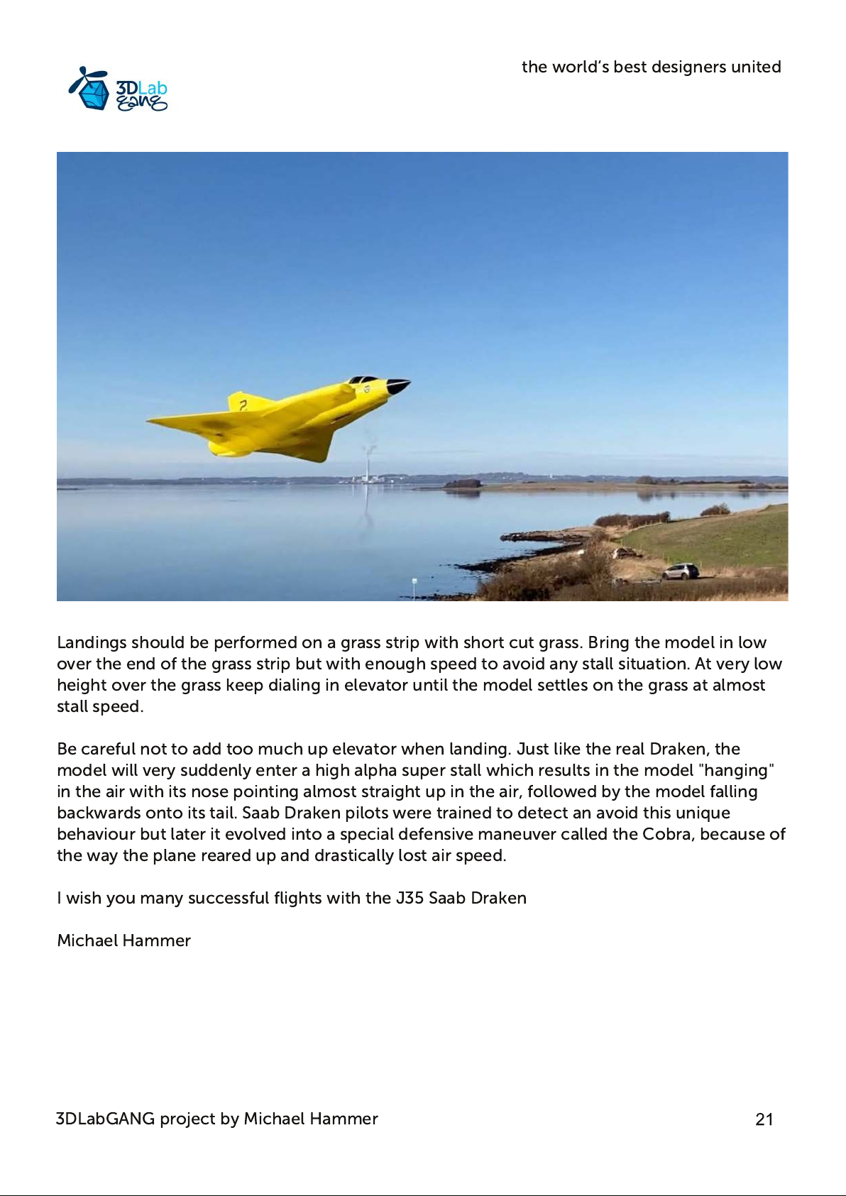
Be careful not to add too much up elevator when landing. Just like the real Draken, the
model will very suddenly enter a high alpha super stall which results in the model "hanging"
in the air with its nose pointing almost straight up in the air, followed by the model falling
backwards onto its tail. Saab Draken pilots were trained to detect an avoid this unique
behaviour but later it evolved into a special defensive maneuver called the Cobra, because of
the way the plane reared up and drastically lost air speed.
I wish you many successful flights with the J35 Saab Draken
Michael Hammer
3DLabGANG project by Michael Hammer
 Loading...