

Page 1

USER MANUAL
3DGence ONE
Page 2

Page 3

3DGence ONE | 3
version 1.0/08.2017
I INTRODUCTION
1. Introductory comments
2. Materials for printing
3. Symbols
3.1. List of symbols used in the manual
3.2. Indicator lights
4. Safet y measures
4.1. General information
4.2. When moving the printer
4.3. Location of machine installation
4.4. Prior to starting the printer
II DESCRIPTION OF PRINTER
1. Construction of printer
2. Contents of equipment
3. User interface
3.1. Main panel
3.2. PAUSE and START but tons
3.3. LCD display
3.4. MENU
III PREPARATION FOR WORK
1. Installation of sof tware and driver
2. Connecting and starting printer
3. Calibration of heatbed
3.1. Indications for calibration of heatbed
3.2. Heatbed calibration procedure
4. Printing material application procedure
4.1. Mounting lament
4.2. Filament removal
4.3. Changing lament during printing
IV FIRST PRINTOUT
1. Launching SD card code
2. Evaluation of operational quality of printer
V SOFTWARE
1. Introduction
1.1. Quality guarantee
2. Installation
3. Quick start
4. Main software interface
4.1. Model control buttons
4.2. Status bar
4.3. Undo button
4.4. Virtual workspace of the machine
4.5. Print prole selection buttons
4.6. Loaded model
5
5
5
6
6
7
7
7
9
9
11
12
12
15
17
17
18
19
20
24
24
24
25
25
25
26
27
28
28
29
29
30
31
31
31
31
32
33
33
36
36
36
36
39
Page 4

4 | 3DGence ONE
4.7. Virtual buildplate of the machine
4.8. Arrow indicating the physical front of the machine
4.9. Printer axis preview
4.10. Prepare to print but ton
5. Preview mode of .gcode
5.1. View options
5.2. Options for previewing layers
5.3. Undo button
5.4. .gcode le preview
5.5. Status bar
5.6. File saving but ton
6. Advanced settings
6.1. Access to advanced settings
6.2. Setting edition window
6.3. Prole sharing
6.4. Advanced proles step by step
7. Support and updates
7.1. Support
7.2. Updating print proles
7.3. Software update
7.4. Update statuses
VI POST-PRINTING OPERATIONS
1. Removing the printout from the device
2. Cleaning
2.1. Cleaning the print head
2.2. Cleaning work table
3. Switching of f printer
VII HEAD REPLACEMENT
VIII CALIBRATION OF AXES
IX MAINTENANCE AND SERVICE ACTIVITIES
1. Autocompensation
X DICTIONARY
40
40
40
40
40
41
41
41
41
41
41
42
42
43
43
44
46
46
47
47
47
36
36
36
36
37
37
39
40
42
42
44
Page 5

3DGence ONE | 5
version 1.0/08.2017
Thank you for choosing 3DGence ONE 3D printer. The following manual shall introduce you to the world of 3D printing. It
enables you to work your way around it, ensures high quality working results and allows safe and effective exploitation
of the device for a long time. 3DGence mission is to of fer exclusively the highest class of devices that meet expectations
of both professionals and amateurs.
On last pages of this manual you will nd a glossary of terms and notions related to 3D printing. It will facilitate the use
of professional nomenclature and explain some concepts presented in this manual.
This manual includes information necessar y for the proper and safe use of the device. Before operating the printer, carefully read all instructions for proper and safe use of the device.
It is forbidden to operate the printer without prior reading this manual. Inappropriate use can damage the unit, cause physical injuries or threaten life and safety of its user.
Starting work with 3DGence ONE printer is tantamount to reading the full content of this manual, understanding and full
acceptance of regulations, recommendations, exceptions and warranty terms contained herein.
I INTRODUCTION
1. INTRODUCTORY COMMENTS
2. MATERIALS FOR PRINTING
3DGence ONE printer uses FFF (Fused Filament Fabrication) technology, which is based on adding layer by layer of plasti-
cized material to form a spatial physical model. It is the basic consumable for the printer. The material used is a lament
in the form of a plastic wire wound on a spool (g. 1). 3DGence ONE uses lament with 1.75 mm diameter.
Fig. 1. Filament spool.
Page 6

6 | 3DGence ONE
There are many different lament materials. Consumables are usually made of substances such as: ABS, PLA, nylon with
various admixtures (e.g. tribo-laments) nylon, elastic materials, enriched with metals, wood, chalk, carbon ber, graphite
and many others. There are many types of materials such as changing colors, luminescent or made of plant bers. The
use of particular material depends primarily on individual requirements and customer expectations - laments have a
variety of properties such as esthetic, mechanical or temperature features. Any used material requires specic, precisely
dened parameters for the correct printing. For more information, see chapter 3, section 4. A growing choice of new 3D
printing materials makes FFF printing one of the most universal tools on the market.
3DGence ONE printer operates within the open system of consumables, which means that it is possible to use laments
of other manufacturers as long as a given material meets the following criteria:
• the diameter of the lament should be 1.75 mm, with a tolerance of +/- 0.05mm,
• the suggested printing temperature should not exceed 265°C.
The use of 3DGence original printing materials ensures obtaining repeatable results.
3DGence shall not be held liable for any aggravation of quality of print resulting from the application of other manufactur-
ers’ laments and consumables. The use of materials from other manufacturers is entirely at user’s risk.
3. SYMBOLS
3.1. List of symbols used in the manual
Markings and symbols used in this manual are given below. They indicate potentially hazardous situations, which could
cause damage to your printer or your health. Always follow instructions under the symbols - any negligence can result in
physical injuries or equipment damage not covered by warrant y.
DANGER:
Indicates a potentially dangerous situation or procedure that could cause injury to the operator. Use safety
precautions.
WARNING:
Indicates a potentially hazardous situation or procedure, which can cause damage to the printer. Use safety
precautions.
PROTECTION:
The operation requires wearing protective gloves included in device equipment. Wear protective gloves.
Page 7

3DGence ONE | 7
version 1.0/08.2017
3.2. Indicator lights
3DGence ONE is equipped with LED indicator lights. The printer’s led lighting provides good visibility during printing; it is
also designed to signal warnings. Below is the description of all backlight colors.
4. SAFETY MEASURES
The information below describes the required conditions for operating 3DGence ONE unit. Failure to comply with indications and contraindications stated therein may shorten the service life of the printer, threat the health of users and result
in violation of warranty terms.
4.1. General information
Don’t install the device:
• outdoors,
• in humid or ood-risk areas,
• in the proximity of volatile or ammable substances,
• near concentrated acids or corrosive fumes,
• in places accessible to children.
COLOR OF INDICATOR LIGHTS STANDS FOR
green Heatbed temperature is safe (below 40°C).
red Heatbed temperature exceeds 40°C.
Do not touch the table – there is a risk of burns.
white Printing in progress Hot table – Do not touch! Serious risk of burns.
yellow
Heating appliances failure. If the print head is installed properly, immediately disconnect the device from power supply and contact 3DGence
technical service.
Color of lighting informs on the temperature of heatbed – not the temperature of hotend! Information on temperature of print head can be found only on display!
You should never:
• touch the printed model, platform, or hotend, once printing is in progress,
• insert any part of the body, or foreign objects into the workplace of the printer once printing is in progress
– this could damage the printer and cause injuries,
• touch the heated nozzle with your hands, even if using protective gloves,
• keep your face close to the heated hotend in the process of printing, it can cause burns on facial area,
• touch any high voltage parts,
• touch axis guides or ball screws in the process of printing,
Page 8

8 | 3DGence ONE
• touch high voltage parts,
• place any objects on or under the heatbed in the process of printing or af ter nishing work ,
• put containers with liquids on the device,
• leave the device unattended by an operator capable of taking necessar y steps in case of a mechanical
failure,
• leave the device unattended in the proximity of children or animals.
3DGence ONE printer heats up to temperature above 250°C; the device has many elements, which make unpredictable, rapid movements during printing. It is forbidden to put any objects or parts of body inside the device
when operating!
You should always:
• use only power sources with grounding (to avoid electric shocks),
• hold the cover of the plug, not the cord, when disconnecting the plug from the power source,
• disconnect the power source prior to the commencement of any repairs or maintenance,
• ensure that the supplied voltage complies with demands stated in specication of the device,
• protect the power plug and cord from damage,
• disconnect the power plug if moving the device,
• disconnect the power plug if the device is not used for an extended period of time,
• periodically clean the nozzle to remove the external contamination (use non-combustible cleaner),
• wear protective gloves when working with the printer,
• ensure the possibility of quick reaction in case of device failure or printing error,
• each time before starting work, examine the workplace near the printer and remove all obstacles for
ensuring free movement of mechanical elements of printer,
• ensure the unrestricted access to the printer.
Heatbed and hotend can still be hot even when printing is nished. The temperature of these elements should
be checked on the display before touching (g. 2). If the device is hot, wait 30 minutes after turning it off (e.g. to
clean, remove the printing model, replace the hotend etc.)
Fig. 2. Temperature parameters:
1. Hotend
2. Heatbed
21
Page 9

3DGence ONE | 9
version 1.0/08.2017
4.2. When moving the printer
To ensure safet y of the user and to avoid unintentional damage, follow instructions below:
• before moving, the device must be turned off and disconnected from its power source,
• the unit must be cooled down, all printing materials, movable parts and accessories must be removed from the
pr inte r,
• the device can be manually lifted in no other way than by its t wo transport handles (g. 3) with the use of protective
gloves attached to the unit’s equipment. The device must not be held or lifted by any other construction elements,
• due to its heavy weight, the unit should not be moved by children or elderly persons.
4.3. Location of machine installation
The printer’s location should meet the following conditions:
• the machine should be operated at room temperature,
• the machine is not designed to work in dusty environments,
• working room should have proper ventilation,
• the printer should be placed on a hard, stable surface,
• the printer must not be exposed to direct sunlight,
• around the working location, the machine should have sufcient free space, which should be measured
based on machine’s external dimensions and operating range of its axes (see g. 4 and 5),
• the machine should be placed away from heat sources and secured against draft,
• location of the device should have 230V/50Hz socket (110V for the US version),
• it is recommended to use UPS emergency power supplies to avoid interruption of printing in the event of
temporary power failure.
The de vic e is powered by 23 0V/50Hz (AC 1 10V f or t he US ver sion). Connec t it t o a po wer outl et wit h a pr o tec t ive
plug (grounding) to prevent electric shock in the event of malfunction of the device.
handle
handle
Fig. 3. Location of transport handles.
Page 10

10 | 3DGence ONE
510,00
195,00
330,00
Fig. 4. Maximum external dimensions of the device, taking into account maximum leaning positions of the worktable.
Fig. 5. Maximum external dimensions of the printer (accessories included) and markings of X, Y, Z axes.
XY
Z
376,00
120,00
380,00
460,00 160,00
Page 11

3DGence ONE | 11
version 1.0/08.2017
4.4. Prior to starting the printer
Before each use of the printer, make sure if the following conditions are met:
• check whether the cables have no visible fraying or other damage. In case of damage of cables, you should immediately notify the 3DGENCE company’s technical service depar tment. In such circumstances, the user is prohibited
from connecting the device to the power supply and/or making repairs on their own,
• make sure the lament is not dir ty, broken, bent or tangled on the spool,
• make sure that in the printer working area there are no items or leftover prints that could cause a jam or damage
the machine,
• check the X and Y axes, and make sure that nothing is blocking their movement. Check that the toothed belts are
pulled tight and have no damage,
• check whether Z-axis stopwatch (g. 6) is not damaged, broken or bent and if it matches Z-axis limit switch (aims
at the notch in limit switch),
• check the correct operation of thermistors (temperature sensors), hotend and heatbed. To do this, start the heating
of the hotend and heatbed and check if temperature parameters on LCD display are rising,
• check that in the area of the printer there are no objects or persons who might be injured as a result of the printer
operating.
stopwatch
Fig. 6. Z-axis limit switch and stopwatch in their.
limit switch
Page 12

12 | 3DGence ONE
To facilitate learning and operating 3DGence ONE printer, the manual contains a number of gures (diagrams) (g. 7–12)
with descriptions of the most important components of the device. Reading the gures and terms can help in understand-
ing terminology widely used in 3D printing.
II DESCRIPTION OF PRINTER
1. CONSTRUCTION OF PRINTER
Fig. 7. 3DGence ONE printer view (lef t side)
1. Extruder
2. Z-axis limit switch
3. Z-axis timer/stopwatch
4. Heated table
5. Filament spool holder
6. Filament cleaner
1
2
6
3
4
5
7
8
9
11
10
7. Control buttons
8. LCD screen
9. MENU buttons
10. SD card slot
11. Power button
Page 13

3DGence ONE | 13
version 1.0/08.2017
Fig. 8. 3DGence ONE printer front view (right side)
12. X-axis guide
13. Ball screws
12
13
14
15
16
17
18
Fig. 9. 3DGence ONE printer view (lef t side)
16. USB port A (ash drive)
17. USB port B (computer)
19
14. Y-axis guide
15. Extruder elements
18. Power inlet socket
19. Fan (warning: do not obstruct)
Page 14

14 | 3DGence ONE
NOTE:
After removing printer from the package, make sure that the extruder lever (element 20) is in correct posi-
tion (as shown in g. 10) and if there is a 7-8 mm space bet ween clamp adjustment screw (element 21) and
extruder clamp (element 23).
Fig. 10. Extruder and head module (front view)
20. Extruder (open/close) lever
21. Clamp adjustment screw
22. Knurl
23. Extruder clamp
24. Tensometers
25. Button releasing the hotend
26. Printing head
27. Printout cooling fan
20
21
22
26
27
25
23
24
NOTE:
Figure 11 presents the print head. The nozzle (element 26), accumulates contaminations in the process the
printing. Deposits accumulated on the nozzle should be regularly removed with the use of non-combustible
cleaning substance. For more information on cleaning the nozzle see chapter „Post-printing operations”, sec-
tion 2.1.
Fig. 11. Printing head module and cooling fans.
27
27
26
Page 15

3DGence ONE | 15
version 1.0/08.2017
Figure 12 shows locations of hot zones marked in red, where the operating machine reaches a high temperature. Touching any elements placed in hot zones before their complete cooling may result in burns!
Zone 1: hotend and extruder zone. Working temperature to 265°C.
Zone 2: heatbed zone; working temperature to 160°C.
2. CONTENTS OF EQUIPMENT
The complete 3DGence ONE set includes the following items. Most of them is placed in the at box shown in g. 13.
• 3DGence ONE Printer,
• spatula for removing printouts (1),
• USB Cable (2),
• lament spool holder (Note: left-hand thread!) (3),
• tweezers (4),
• SD memor y card (5),
• USB memory stick with sof tware (6),
• cleaner with handle and teon wire (7 ),
• power cable (8),
• protective gloves (9),
• lament spool,
• hotend with nozzle with a diameter of 0.4 mm (already installed),
• panels made of polycarbonate (g. 14) (sides, depending on the color version: red, blue or orange) (11),
• additional hotends (optional) (10),
• 3DGence Slicer.
Fig. 12. Extruder and cooling fans.
2
1
Page 16

16 | 3DGence ONE
1
2
3
4
5
6 7
8
9
10
11
Fig. 13. Distibution of accessories in the package.
Fig. 14. Panels made of polycarbonate (sides, depending
on the color version: red, blue or orange).
Page 17

3DGence ONE | 17
version 1.0/08.2017
3.1. Main panel
Below is shown the main panel of 3DGence ONE. It consists of 11 buttons, divided into t wo functional groups. The func-
tions of two of them (Pause/Start) are discussed in the next subsection.
Right panel
3. USER INTERFACE
Buttons in this group are for navigating MENU. They provide access to all parameters in the menu and allow adjusting
their values.
Function of buttons (g. 15):
1. Navigation key OK - entering MENU and conrming selection.
2. Upwards Menu navigation button (and values changer).
3. Instant le preview on SD card.
4. Key down navigation menu (and values changer).
5. Menu Navigation button and menu return.
Left panel
WARNING:
Lef t control panel operates outside of traf c restrictions (by micro switches), damage caused by improper use
is not covered by the warranty (buttons from 1 to 4).
2
4
35
1
Fig. 15. 3DGence ONE navigation panel: 1st group of buttons.
Fig. 16. 3DGence ONE navigation panel: 2nd group of buttons
1
3
24
Page 18

18 | 3DGence ONE
Function of buttons (g. 16):
1. Upwards table adjustment button, one click moves the table by 0,025mm, which enables adjusting the height of the
table during printing (the but ton is active after referencing Z axis).
2. Add lament button (active after the hotend reaches 185°C). Allows control of feeding the material during printing. The
button allows to ll the unnished spaces/losses on individual layers or ll up the print head before the commencement
of printing.
3. Downwards table adjustment button, one click moves the table by 0,025mm, which enables adjusting the height of the
table during printing (the but ton works after referencing Z axis).
4. Filament recognition button (active from 185°C). Allows removing material from the head.
Applies to PLA material, in the case of ABS, set hotend temperature to 240°C to use quick access keys.
WARNING:
Buttons in point 2 and 4 are to be used after the head has warmed up to the temperature recommended by
the manufacturer of the material. If not used properly, it may cause damage to the hotend.
3.2. PAUSE and START buttons
To increase functionality and facilitate the use of the printer, 3D Gence ONE unit has been equipped with PAUSE button
(g. 17) (1) that has the following functions:
• a single-press will stop the printing process,
• a double-press will hold the printing process and the departure of the nozzle to X and Y axes base position.
This function allows modif ying the printed object e.g.: inserting a cap (or other object) to a specially prepared socket
and fur ther printing on the surface of the inserted object, changing the color of the lament, or, if the printing material
runs out, replacing an empty spool. However, for the replacement of printing material it is recommended to use lament
replacement guide „Filament change” from the MENU. Note that the added objects cannot protrude beyond the currently
existing printing surface; otherwise the head can collide with the added object and be damaged.
When changing the printing material, it is recommended to hold the printing process at the stage of printing the lling,
which reduces the risk of possible defects on the surface of printing model.
WARNING:
Always wear protective gloves for any manual operations within the working area.
To resume the printing process press START button (button 2, g. 17), regardless of whether PAUSE but ton was pressed
once or twice.
21
Fig. 17. 3DGence ONE navigation panel:
1. PAUSE
2. START
Page 19
3DGence ONE | 19
version 1.0/08.2017
3.3. LCD Display
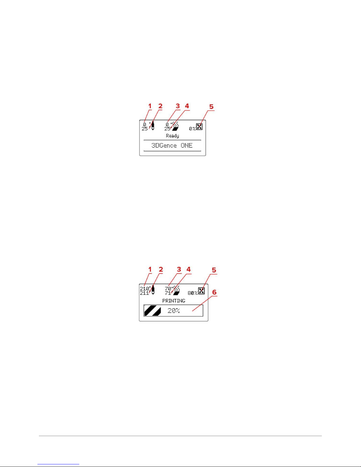
LCD display enables accessing all MENU functions and direct control of important parameters of 3DGence ONE printer
such as hotend and heatbed temperature. Location of particular parameters on LCD panel is presented below.
After starting the printer it displays the following information (g. 18):
3DGence ONE printer displays the following information:
1. Hotend temperature,
2. Current temperature of hotend (as indicated by temperature sensor),
3. Heatbed temperature,
4. Current temperature of heatbed (as indicated by temperature sensor)
5. Blow power of cooling fans ( %).
After starting printing, LCD panel displays the following information (g. 19):
Fig. 18. 3DGence LCD display after turning on.
Fig. 19. 3DGence LCD display while printing.
Information currently displayed:
1. The introduced hotend temperature,
2. Current temperature of hotend (as indicated by temperature sensor)
3. The introduced heatbed temperature,
4. Current temperature of heatbed (as indicated by temperature sensor)
5. Blow power of cooling fans ( %).
6. Printing progress panel (graphic presentation and percentage).
Page 20
20 | 3DGence ONE
Temperature parameters and fan power can be changed during the printing process. Parameters can be manually ad-
justed for the purpose of printing process optimization. For example, strong airow should not be used during printing
the rst layer, for this reason the obtained read may be 0%. Machine code automatically star ts the cooling fan at the
appropriate stage of printing. Fan settings can be changed from the MENU - Fan Speed.
LCD panel can also display information on total printing time and the amount of printed material from the initial starting of
the printer. To access this data press the arrow down but ton (4, Fig. 14) on the right side of the panel from the main MENU.
3.4. MENU
3DGence ONE has an extensive user interface allowing full control of the printer without connecting it to a computer. For
accessing MENU press OK button on the main panel (button 1, Fig. 14). To navigate MENU use navigation buttons on the
right side of the panel (see chapter “Main Panel” - buttons 2, 3, 4, 5, Fig. 14).
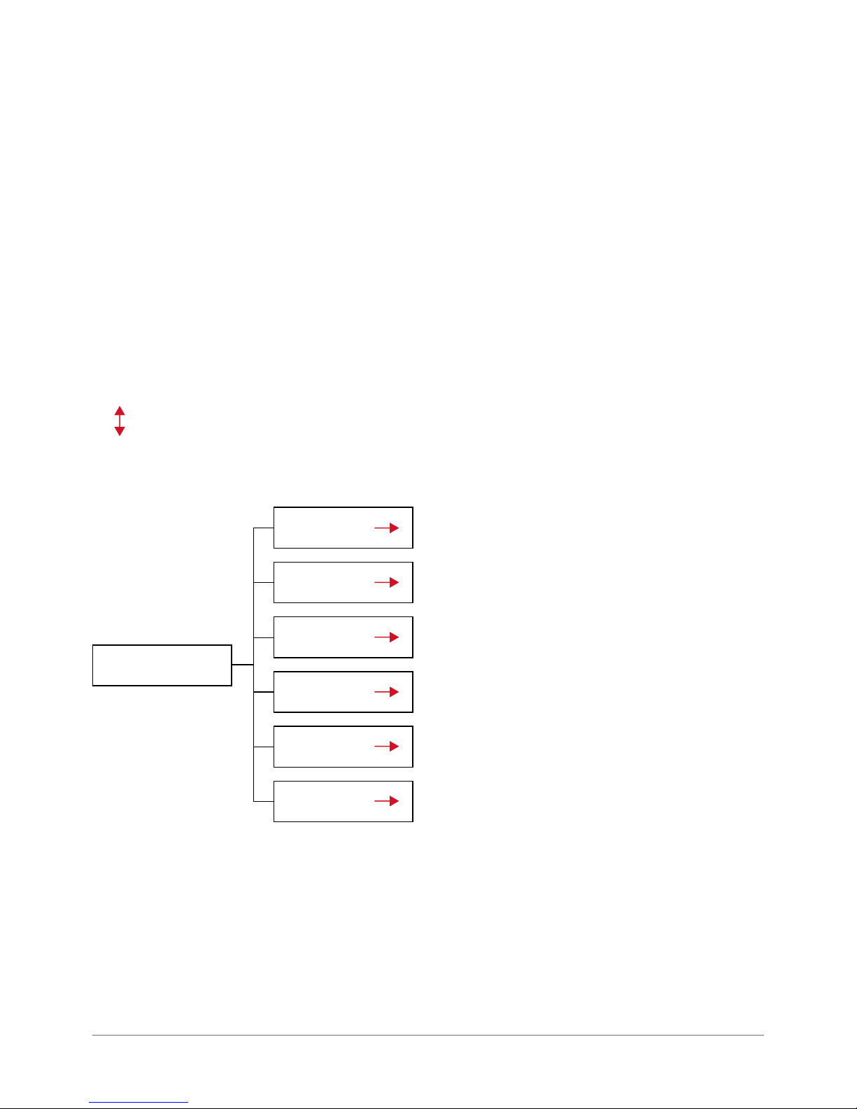
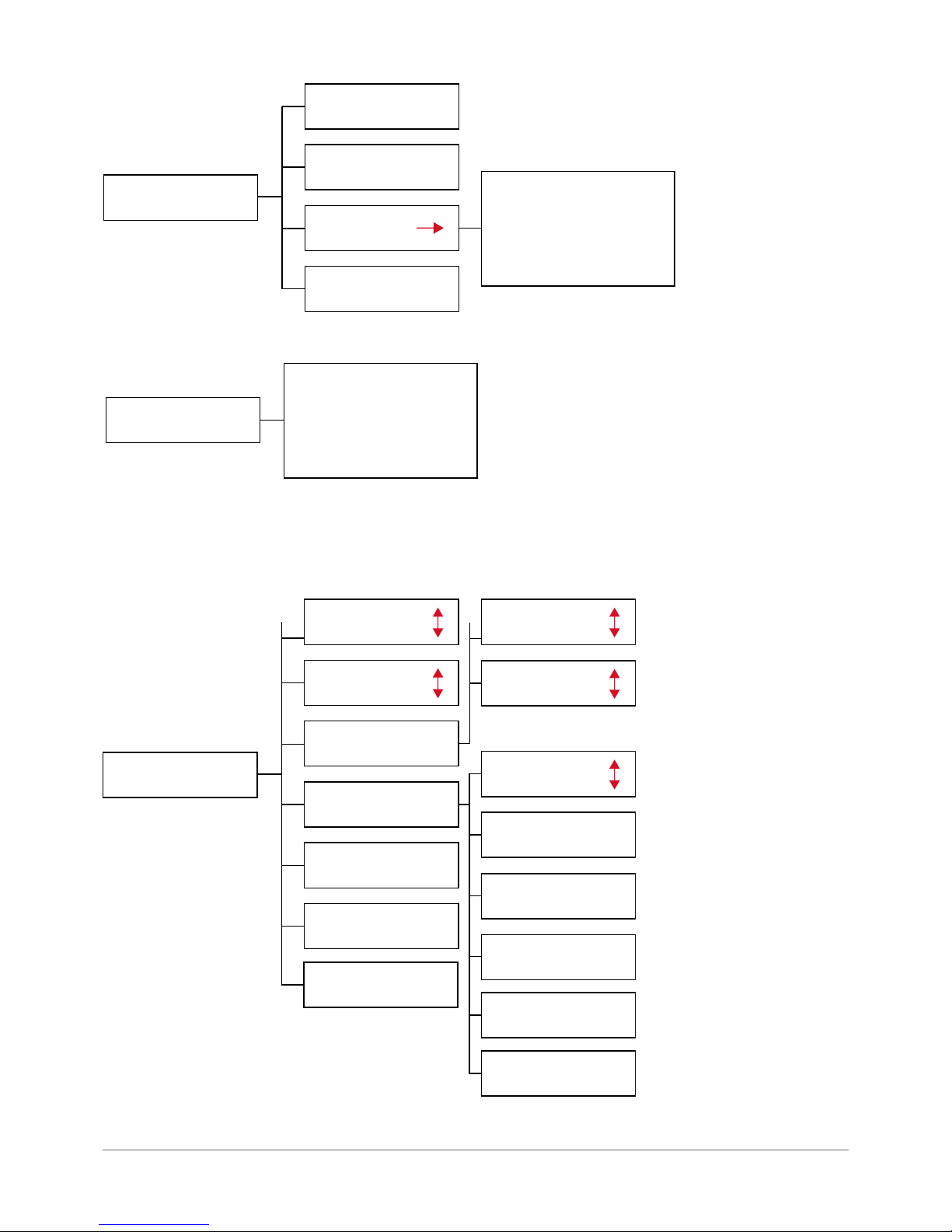
Diagram of the Menu and description of available functions are presented below. The displayed functions of menu can
change depending on the printer’s current operation mode (active or idle). Here is an example of menu in idle mode:
The symbol shown stands for choosing the option for up and down parameter regulation after pressing OK button.
OK button
Prepare
Print
Tune
Calibration
Conguration
Info
Fig. 20. Main menu in idle mode.
Page 21
3DGence ONE | 21
version 1.0/08.2017
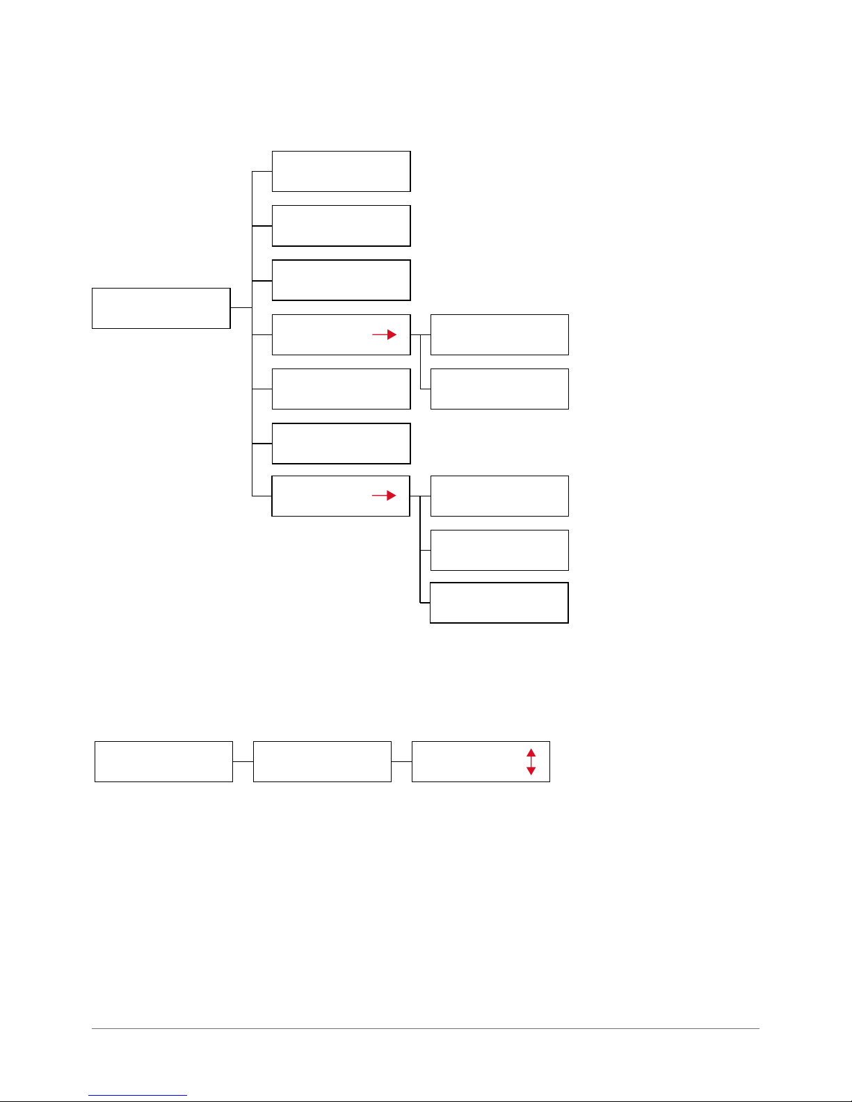
From this level you can enter a given selection settings:
Prepare
Home all
Load lament
Unload
lament
Preheat
Cooldown
Hotend change
Park heatbed
Preheat PLA
Preheat ABS
Up
Middle
Bottom
Fig. 21. PREPARE menu.
Print
Print le
Content SD Card
Fig. 22. PRINT menu.
Page 22
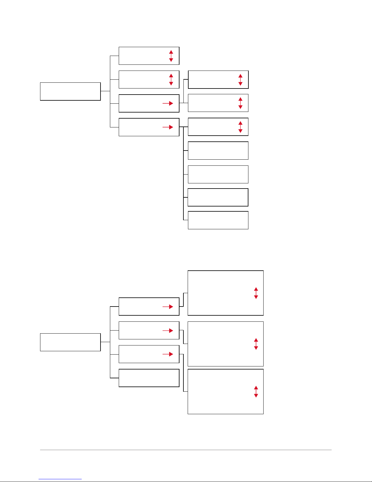
22 | 3DGence ONE
Tune
Speed
Multiplier
Flow
multiplier
Temperatures
Fan speed
Heatbed
Fan speed
Set fan: 25%
Set fan: 50%
Set fan: 75%
Fig. 23. TUNE menu.
Nozzle
Set fan: 100%
Callibration
XY callibration
Autocomp.
settings
Probe position
Heatbed scan
Org X 150.00 mm
Print X 150.00 mm
Org Y 150.00 mm
Print Y 150.00 mm
RESET
CALCULATE & SAVE
Z offset: 0.00 mm
Pressure: 80
RESET
SAVE
Pos X: 2 (20 mm)
Pos Y: 2 (20 mm)
RESET
SAVE
Fig. 24. CALLIBRATION menu.
Page 23
3DGence ONE | 23
version 1.0/08.2017
Conguration
Lights
Beeper
Hardware test
Factory reset
Home Z
Lights test
F: 537
Endstop status
X: Of f, Y: Off, Z: Of f
Fig. 25. CONFIGURATION menu.
INFO
NAME: 3DGence ONE
HW: Titanium v 1.1
SW: v 3.1
BD: 23.02.2015
Total time: 17d23h
Total Fil: 2216.1m
Fig. 26. INFO menu.
In active mode, the printer’s menu displays different information. A printed model can be instantly modied by changing
parameter settings during printing. Instant parameter correction may be necessary when the amount of material fed is
too small or the cooling is not ef fective.
OK button
Speed multipiler
Flow multipiler
Temperatures
Fan speed
Filament change
Lights
Abort print
Heatbed
Fan speed
Turn fan OFF
Set fan: 75%
Nozzle
Set fan: 25%
Set fan: 50%
Set fan: 100%
Fig. 27. OK menu.
Page 24
24 | 3DGence ONE
The 3DGence ONE printer does not require any additional drivers. The only program required to operate the device
is the 3DGence Slicer software that generates a machine code. For more information on 3DGence Slicer refer to the
SOFTWARE chapter.
Printer rmware are subject to periodic update. It is important that drivers are always updated to the newest version.
The latest printer driver is available at:
ww w.3dgence.com – tab: Support – Software/Firmware
The procedure of rmware update proceeds as follows:
1. Download the rmware le from the website above (the proper le has the .hex extension).
2. Download the free Xloader program to upload rmware to the printer driver.
3. Plug in an USB cable to printer USB por t.
4. Plug in an USB cable to computer USB por t.
5. Wait until new hardware installer operation is completed, if it has been star ted automatically. Pay attention to and
memorize the port number assigned to the printer, e.g. COM4.
6. In Xloader program in Hex le box mark the newly loaded rmware le.
7. In COM port box mark the port assigned to the printer. In Device box set the Mega(ATMEGA2560) option. Remaining
information should be left unchanged.
8. Press the Upload key. Loading the new software may take a few minutes. During the loading process, printer display
can show color ful artifacts (graphical noise), this is however completely normal. Update success will be conrmed by
an appropriate message displayed on the computer screen.
9. Now you can remove the USB cable from the printer and turn off the printer.
10. Load the init.g le into memor y card and insert it into the SD card slot of the printer.
11. Turn on the printer and wait for the sound signal. It informes that the conguration has been succesfully loaded.
III PREPARATION FOR WORK
1. FIRMWARE UPDATE
2. CONNECTING AND STARTING PRINTER
1. If the printer is star ted for the rst time follow instructions from „Quickstar t” char t included in the package set.
2. Place the device on a at and stable surface and connect it to the power source with the use of power cable. Power
inlet socket is located at the rear of the device (g. 28).
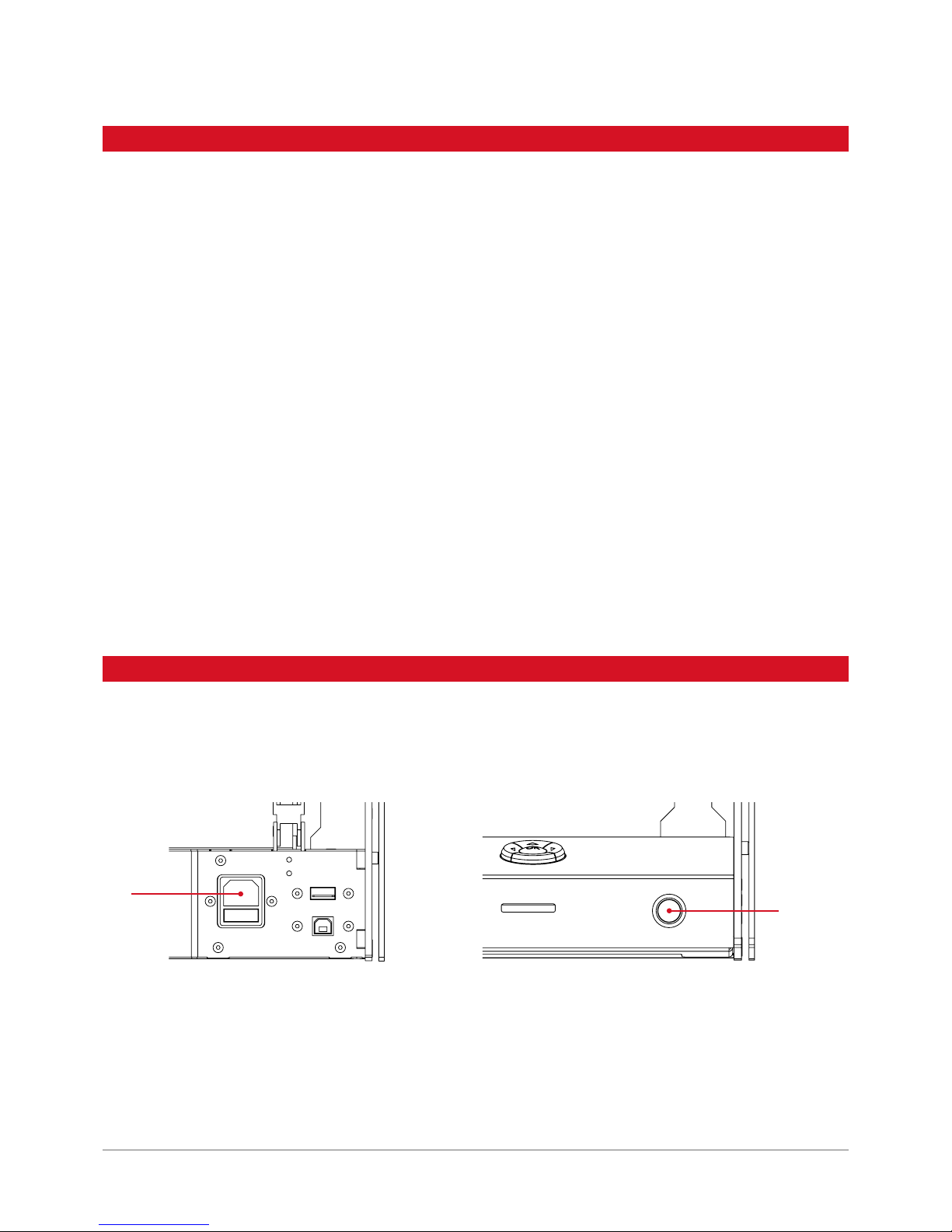
1
Fig. 28. Location of power inlet socket (1). Fig. 29. POWER button location (1).
3. To start the device press POWER button on the right side of the main panel (g. 29).
4. Af ter star ting the printer, set all axes to their initial positions. To do this, select Home All option from the submenu
Prepare - go to main menu level and press OK button three times. At this point, all axes go to their base position.
5. After that, the unit is ready for fur ther preparatory steps.
1
Page 25

3DGence ONE | 25
version 1.0/08.2017
3. CALIBRATION OF HEATBED
3.1. Indications for calibration of heatbed
Heatbed calibration is not required each time you run the printer - it should be done approximately once a few dozen to
a few hundred hours of printing. Other indications for table calibration are enumerated below.
Heatbed should be calibrated when:
• the printer is started for the rst time,
• one or more corners or edges of printed model peels off or does not adhere to the working table,
• one or more corners or edges of printed model are squeezed into the surface of heatbed (the printed layer seems
transparent or too thin, printing mechanism skips layers, extruder engine makes a clicking noise or printing material
excessively accumulates in transitions between layers),
• table surface was unintentionally lifted from its bed,
• too much force was used during removal of the printout, which might have caused table displacement,
• the rst printing layer is not even - one edge is printed correctly, whereas the other edge is too at or does not adhere to the sur face of the heatbed.
3.2. Heatbed calibration procedure
1. Check if X and Y axes can move without any obstructions. Make sure if any cables are not frayed or damaged. Check if
the toothed belts are not frayed or damaged. Check if Z-axis stopwatch is not damaged, broken or bent, and if it matches
Z-axis limit switch (if it aims at the notch of Z axis limit switch).
2. Any lament lef tovers should be removed (see „Removing lament”) and the head should be cooled down to temperature below 50°C.
3. Remove all dir t and leftover material from the nozzle of print head and clean the table with a spatula (not required when
star ting the device for the rst time).
4. From the submenu „Prepare” select „Home All” and conrm by pressing „OK” button. At this point, all axes will go to
their base position.
WARNING:
Carefully observe the movement of all axes. When Z axis reaches its limit switch, check the distance
between the end of hotend and the heatbed. It should be about 0.8-1 mm (no more than 1 mm), greater
distance may interrupt scanning the heatbed, which is displayed as an error „Heat bed scan aborted!” If
the distance between the hotend end and heatbed is more than 1 mm, adjust it manually to 0.8-1 mm. To
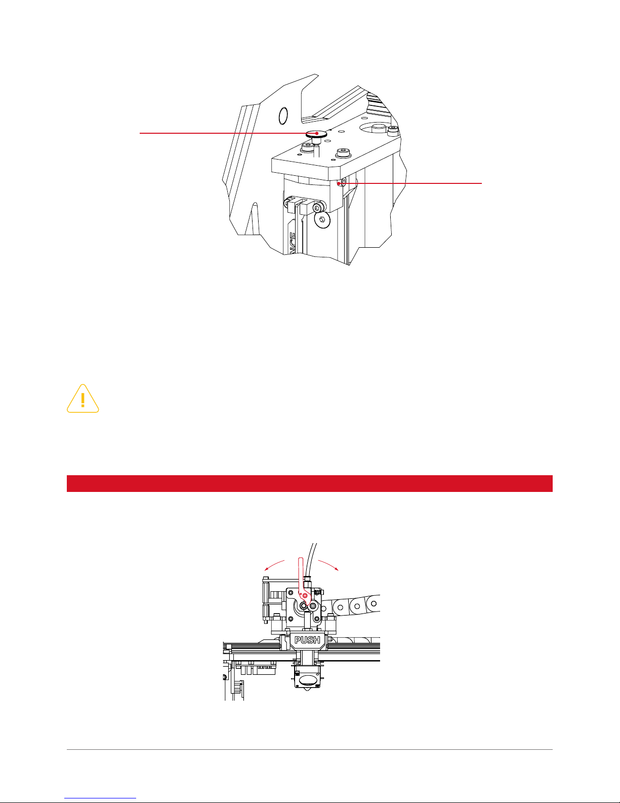
do this, release the screw (1) (g. 30.) and adjust the distance using the knurled screw (2). Turning the
knurled screw clockwise will increase the distance between the table and the head. Counter-clockwise
turn will decrease the distance. A single full turn increases or decreases the distance by 0.5 mm. Once
you have nished knurled screw adjustment, check the position of the nozzle with the command HOME Z
and tighten the screw (1) again.
Page 26
26 | 3DGence ONE
5. Select Calibration and Heatbed Scan. At this point, the device star ts the table calibration process.
6. During calibration, do not touch the head or the extruder – the calibration process can take up to 25 minutes. Af ter the
scanning is completed, the display shows information HEATBED SCAN COMPLETED. The printer was calibrated success-
fully.
WARNING:
During calibration, do not touch the head or the extruder. It may disrupt calibration, which is displayed as
an error „HEAT BED SCAN ABORTED”. This message may also appear if the instruction from point 3 was not
followed. The calibration process can take up to 25 minutes. In the event of hearing a loud „clicking” sound
coming from the engine, or if one of axes did not stop, immediately turn off the device and contact 3D Gence
technical ser vice department: [email protected]
2
1
Fig. 30. Hotend height adjustment screws.
4. PRINTING MATERIAL APPLICATION PROCEDURE
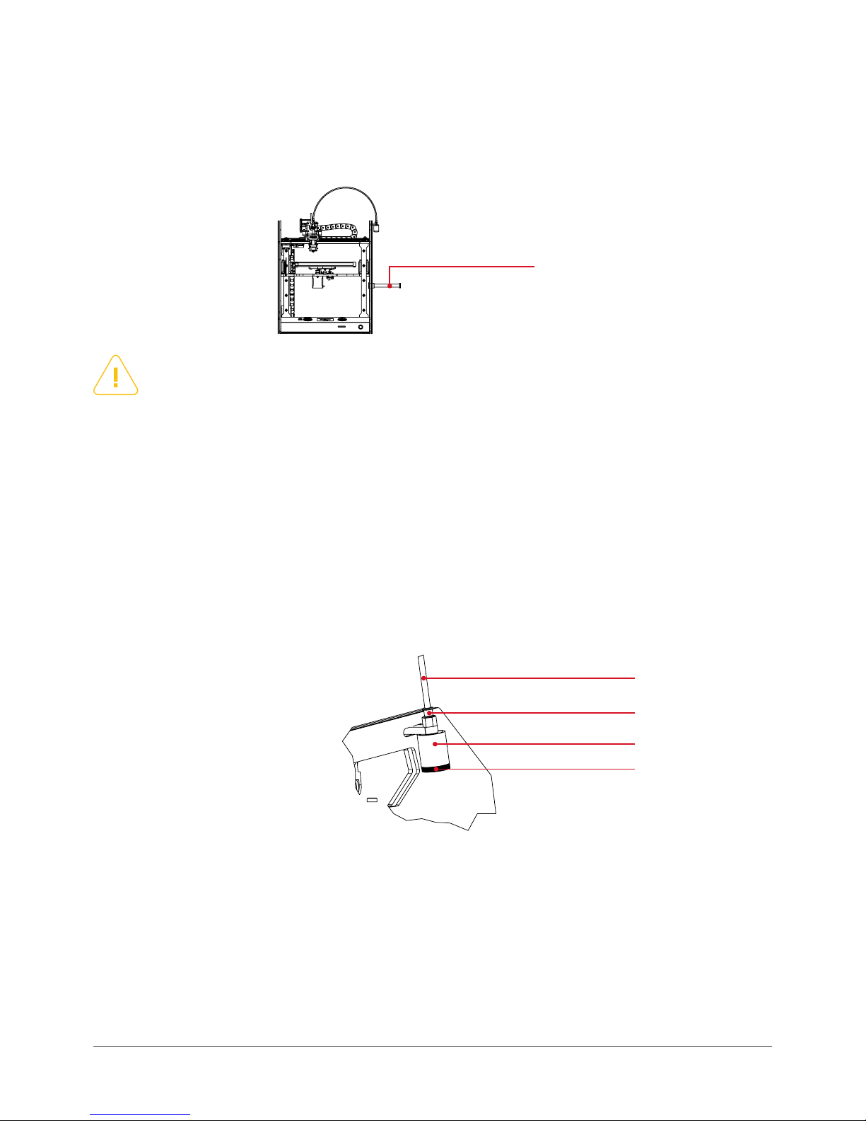
All further steps require opening and closing the extruder with the use of extruder lever marked red in the g. 31 below:
Fig. 31. Extruder lever positions.
Page 27
3DGence ONE | 27
version 1.0/08.2017
NOTE:
The nut on the handle has a left hand thread! For loosening, spin the nut clockwise, for tightening counterclockwise!
2. Unpack the spool with the lament at tached to the device.
3. Release the sealed end of the material and cut the ending with scissors or pliers. The ending cannot be crushed or deformed.
4. Place the spool on the handle.
5. Place the lament in the cleaning tool (see . 33). Follow the instruction below:
• remove the Bowden (tube) from the cleaner by pressing and holding the red clamping ring of pneumatic connector (2) and
pull the tube out (1);
• unscrew the cleaner’s nut (4) and remove the sponge inlay;
• pass the lamen t thro ugh the hole of the cleaner ’s nut (4) and pierce the sponge locat ed in the cleaning tool wit h the tip of lament ;
• pass the lament through the sponge (3), insert the lament and the sponge to the cleaning tool and tighten all with the
cleaner’s nut (4);
• push the lament wir e through a tube (Bowden) (1), straighten the end of it and inser t it into the cleaner’s pneumatic connector (2).
6. Select „Load Filament” in Prepare menu and follow instructions on LCD panel:
1
2
3
4
4.1. Mounting lament
1. Install in the spool holder on the right side of the device (turn counterclockwise) (g. 32).
The device will heat up the hotend to 240°C and start extruding the printing material. Next:
• open the extruder by moving its lever to the lef t (counter clockwise);
• straighten the end of lament and insert it to the hotend (min. 5 cm from the inlet of ex truder);
• close the lament inside the extruder by moving the lever right (clockwise);
• after the printing hea d is suf ciently lled with the new mater ial (approx. 5 cm of lament should be pushed thr ough when
changing the color of the lament), press „OK” but ton to stop loading lament;
• remove the material leak from the head with the use of tweezers.
7. LCD panel should display information that loading lament was completed successfully. Press “OK” button to conrm.
Fig. 33. Constructing of the cleaning tool.
Fig. 32. Location of the spool holder.
1
Page 28
28 | 3DGence ONE
WARNING:
The head heats up to 240°C and then the device starts extruding a few millimeters of material. This prevents
a possible clogging of the material in the hotend.
• open the extruder by moving the lever to the left (counterclockwise),
• rmly grasp the lament on the hotend, pull it out with one vigorous stroke and press OK button to conrm cleaning
the head.
Always store the lament in a dry and dark place. The lament may absor b humidit y or be deformed when exposed to sunlight. In both cases, the use of such a lament may cause difculties or faults such as not adhering to the working table.
WARNING:
Do not remove the lament from the inside of the hotend without heating the hotend and opening extruder
lever! It may damage the hotend. Hotend should not remain heated, regardless of whether it is full of printing
material or empty. The hotend can be heated for a long time only in the process of print (during extruding of
heated printing material).
4.3. Changing lament during printing
The material on the spool may run out before the printout is nished. For quick replacement of lament spool or changing
the color of lament (in two color or multicolor prints), use lament change assistant. The current printing will be paused
without cancelling printing operation. Printing is restored after conrming and closing lament change assistant.
Before starting printing the system displays the amount of material required to complete a par ticular printing object.
Make sure that you have enough printing material.
1. Go to the printer ’s me n u (menu is re c a lled by pressin g „OK” button during printing). Choose “Filament Change” and press
”OK” to conrm.
Printing will be paused and all mechanisms will go to their safe points.
2. Open the extruder by moving its lever to the lef t.
3. Pull out the lament with one vigorous upstroke.
4. Plac e the ne w lame nt spool on the handle an d pas s its lo ose end th r ough the cleane r and the tube (Bow den). Str aig hten the tip of lament. Make an even cut on the tip if necessar y.
5. Inser t at least 5 centimeters of lament wire to the extruder.
6. Close the extruder by moving the lever to the right and press „OK” to conrm.
The printer will ex trude a certain amount of lament for correct lling the printing head.
7. Remove the ma t e r i a l leak from th e head wit h the us e of tw e e z e r s . Conrm comp l e t i n g the proced u r e by pressin g “OK” button.
3DGence ONE printer will continue printing with the new material from the point, where the process was stopped for
changing lament. It is recommended that the lament should be replaced at the stage of printing the lling (for the purpose of masking the transitions between different materials).
4.2. Filament removal
To remove lament from the extruder (to replace it or to clean the head):
1. Select Unload Filament from Prepare menu and follow instructions on printer’s LCD panel.
Page 29
3DGence ONE | 29
version 1.0/08.2017
First printing can be started under the following conditions:
• location of the device meets all conditions stated in chapter 4.3.,
• the device is properly connected to power supply,
• all axes and limit switches move without any obstructions,
• heatbed is properly calibrated,
• SD memor y card is properly inserted,
• lament is mounted properly,
• all readings of the printer are correct.
IV FIRST PRINTOUT
1. LAUNCHING SD CARD CODE
WARNING:
Starting the rst print without meeting the conditions specied in this user manual (chapters DESCRIPTION OF
PRINTER, PREPARATION FOR WORK) can result in equipment damage or cause injury to the operator. Always
follow instructions for safe operation – even if you are an experienced operator.
Use 3DGence print testing le from the included SD memor y card. For more information on le preparation, format of
les and method of conversion, see chapter SOFTWARE. The initial print will help determine if the printer is functioning
properly.
For making the rst printout:
1. Turn on the device with POWER button.
2. Go to main menu by pressing “OK” button. Select the option “Print” using navigation buttons up - down on the right
panel. Conrm again by pressing ”OK” button.
3. Select „Print File” and press „OK” to conrm.
4. Now you have access to all G-code les and subfolders on SD card.
G-code les are instructions for the printer – only these les can be used for starting printing.
5. Conrm selection of one of the les by pressing „OK” button.
The printer starts heating the hotend and heatbed. After reaching the exact temperature, the device will measure the
parameter of height for the hotend. Do not press the table surface or touch the head during the measurement - it may
cause interruption or incorrect readings. Next, the device will extrude a sample strap of printing material near the edge
of heatbed. This is to ensure that the hotend is properly lled with the material before starting printing.
Depending on the selected le, the printing can take from one to three and a half hours.
• 3D_keychain – 1 hour;
• calibration XY – 1 hour 45 minutes (printing calibration solid – see chapter „Calibration of axes”),
• phonestand – 3 hours 30 minutes.
After the completion of printing the hotend returns to a safe position and the printout is cooled. Wait until progress bar
for cooling reaches 100%. When the printout is cooled, you can safely remove it from the heatbed. For more information
see chapter „Post-printing operations”.
For starting any next printing, the device must be cooled down. All printing leftovers and material contaminations (pieces
of plastic, lumps in the hotend) must be removed.
Page 30
30 | 3DGence ONE
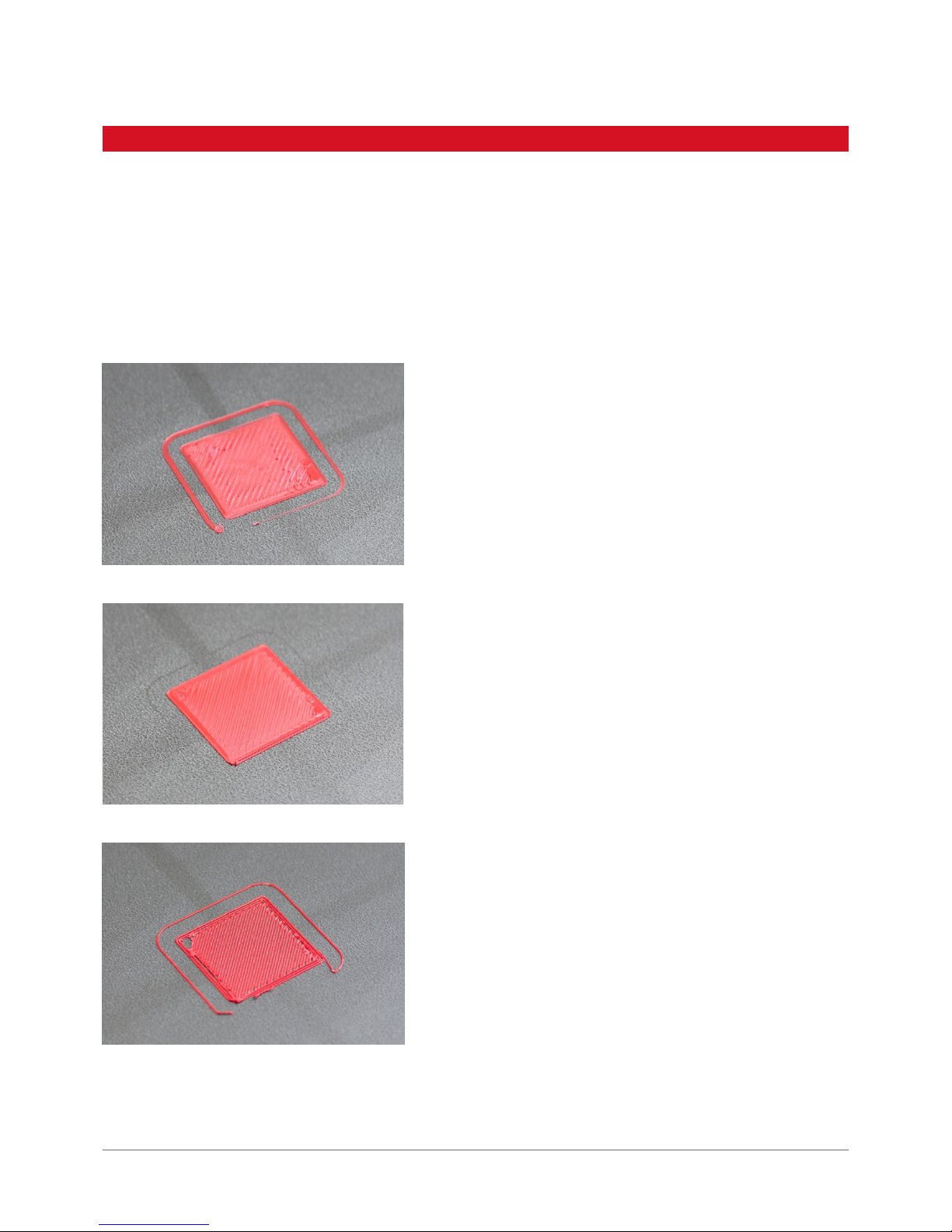
During the rst printing there may occur some difculties in applying the base layer of material, which is crucial for the
entire printing process. Compare your printout with the below photographs.
Photographs illustrate the following problems:
• hotend too high,
• hotend too low,
• hotend in correct position.
2. EVALUATION OF OPERATIONAL QUALITY OF PRINTER
Hotend too low
The material is pushed out of the hotend while
printing the rst layer. It leads to deformation of
the base of the printed model. It’s an indication to
recalibrate the heatbed.
Hotend in correct position
The material is laid out regularly. Whole surface of
the model’s base is covered with plastic and the
upper sur face of the rst la yer is a regular, at and
lithe plane.
Hotend too high
The distance between the heatbed and the hotend
is too large. It causes a poor adhesion of the material to the heatbed. It may lead to the model to
be peeled off during printing. It’s an indication to
recalibrate the heatbed.
Page 31
3DGence ONE | 31
version 1.0/08.2017
Dedicated 3DGence Slicer sof tware with a pre-dened print proles for specic materials was prepared for 3DGence
printers. This software is designed for preparing machine codes, i.e. gcode, based on CAD les in STL and OBJ format.
The producer provides comprehensive support when using pre-set printing proles in the sof tware and recommended
printing materials.
Expert users may modif y the advanced print settings. Due to the nature of such modications, the producer does not
guarantee the quality and repeatability of printouts prepared in this way.
The producer guarantees the highest possible quality of models produced with the dedicated software and materials.
If the user detects any defects in the produced models or soft ware errors when using the software, please contact us by
e-mail and attach a photo/screenshot and description of the defect and, if possible, a .gcode and .stl le. Every model
submitted to the manufacturer in this way will be assessed and/or printed in the company ’s headquarters. The producer will suggest a solution, advice, initiate maintenance activities (if required), prepare .gcode executable le or update
printing proles accordingly.
The software should be downloaded from the producer’s website. The recommended hardware requirements to initialize
the soft ware are as follows:
• Windows 7 or later,
• screen resolution 1920x1080 pixels,
• 4 GB RAM,
• dual-core Intel Core i3 or later.
The soft ware may be initialized on hardware not meeting the above requirements but this may signicantly compromise
the comfort of work and model processing speed. The producer does not provide support for any hardware not meeting
the above system requirements, especially for older operating system versions.
During the rst start-up of the soft ware the user will be asked for consent for automatic updates of print proles. We
recommended selecting that option to achieve the highest possible model quality. This option may be enabled or disabled
any time. The updates take place during every software star t. Proles may also be updated manually.
1.1 Quality guarantee
V SOFT WARE
1. INTRODUCTION
2. INSTALLATION
Page 32
32 | 3DGence ONE
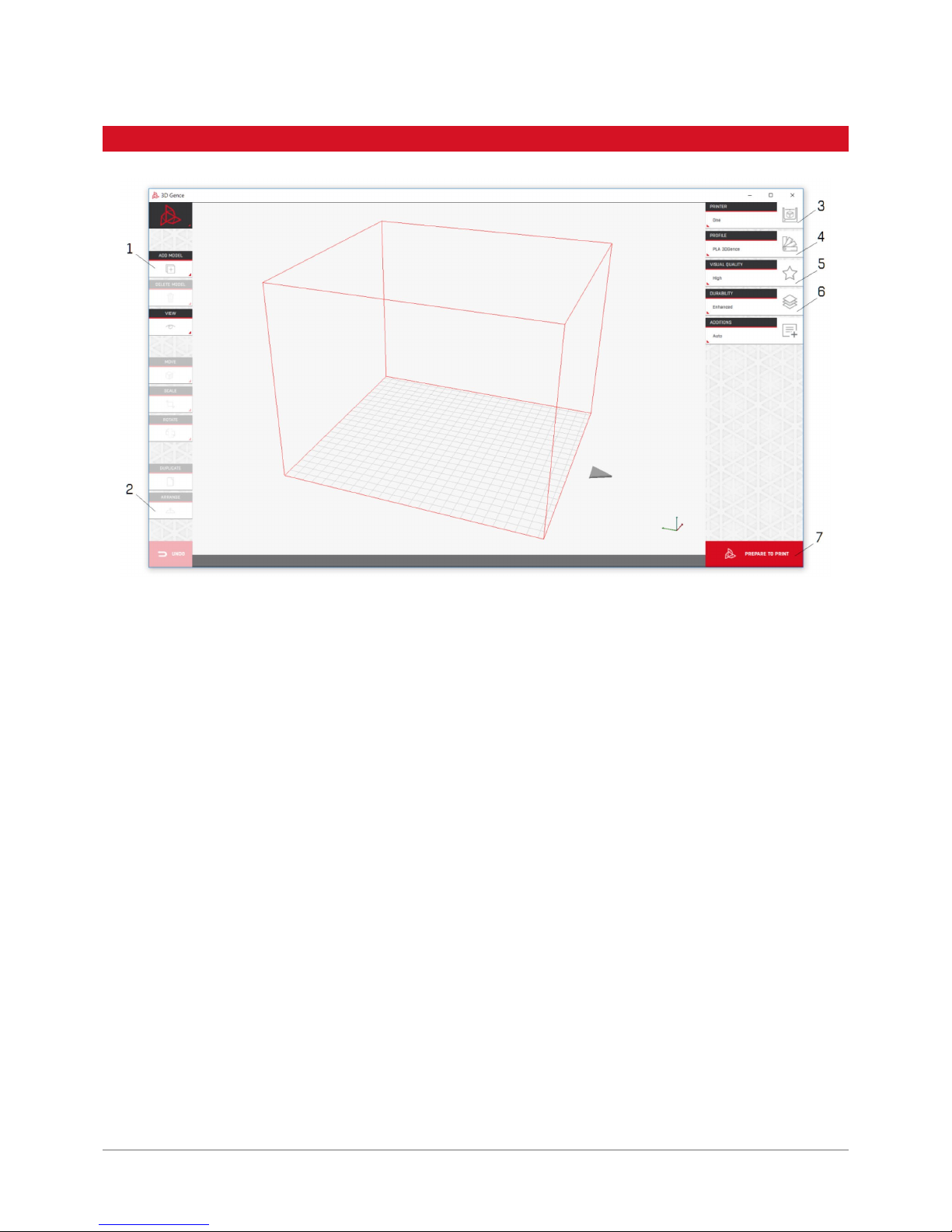
1. Load .stl le of your solid or solids with the „Add model” button or by dragging the les to the main sof tware window.
2. Ensure the models are arranged properly in the workspace with the „Arrange” button.
3. Select the printer you want to use to make your model.
4. Select the material you want to use to make your model.
5. Select the visual qualit y expected (better quality means longer printing time).
6. Select your models desired durability.
7. Prepare your le with the „Prepare to print” button.
8. Save the executable .gcode le to SD card with the „Save File” button which replaces the „Prepare to print” but ton in
the bottom right corner.
9. The le can be read out in the printer control panel. The le will be accessable from the printers „Print” menu.
3. QUICK START
Page 33
3DGence ONE | 33
version 1.0/08.2017
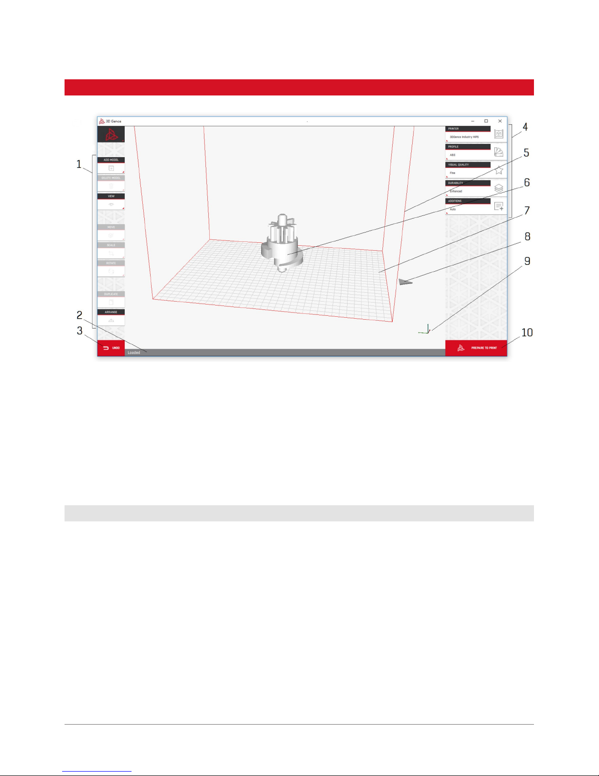
1. Model control buttons.
2. Status bar.
3. Undo last action function.
4. Print prole selection buttons.
5. Virtual workspace of the machine.
6. Loaded model.
7. Virtual buildplate of the machine.
8. Arrow indicating the physical front of the machine.
9. Printer axis preview.
10. Print preparation/le saving but ton.
The buttons that are not active at a given time (e.g. as you have not selected any model) are greyed out.
Add Model: enables to locate and import a le in .stl format to the software. You can select several les to be imported
simultaneously. You can also use the function of dragging .stl les onto the main software window. The models can be
removed from the workspace by lef t-clicking them and using „Delete Model” button or pressing Delete or Backspace on
the keyboard.
Delete Model: deletes a currently selected model.
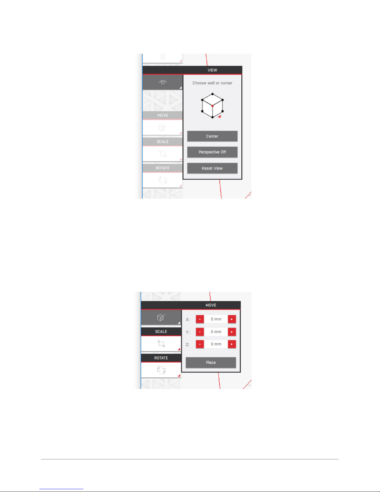
View: camera settings can be changed.
4.1 Model control buttons
4. MAIN SOFTWARE INTERFACE
Page 34
34 | 3DGence ONE
The cube enables the user to select a predened point of view. The „Center” button sets the camera to the workspace
centre. The „Perspective” button enables you switch the perspective on and off. The „Reset View” button restores the
default camera settings and can be used to restore view of the model after inappropriate movements have been made.
It is also possible and recommended to move your camera with a right mouse button or touchpad. The left mouse button
selects or deselects the model. The right mouse button enables to rotate the camera. The right mouse button with the
keyboard Shif t pressed enables to move the camera. The mouse scroll wheel enables zooms the view in or out.
Move: enables the user to move the selected model in the virtual workspace.
Text elds marked X, Y and Z move the model by 1 mm (each press when using the buttons) or any distance when you
enter the desired value in the text elds. The star ting point (0,0,0) is calculated from the buildplate centre. The „Place”
button enables to place the model on the buildplate. It is not possible to select the wall the model is to be placed on, other
than rotating in manually.
Page 35
3DGence ONE | 35
version 1.0/08.2017
It is also possible to move the models with a mouse. Click and hold the model with the Move option selected. This will
enable you to move thr model in the XY plane freely.
It is permissible though not recommended to put one model on top of another. Printing will not be possible if you have
moved any models outside the workspace.
It is permissible though highly not recommended to set intersecting solids as this may result in the sof tware producing
invalid les and a resulting errors.
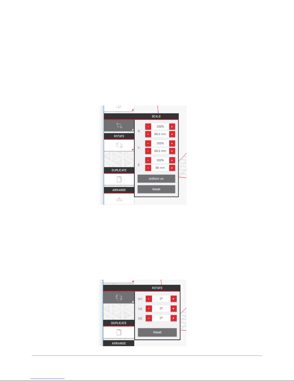
Scale: changes the model size.
Text elds marked X, Y and Z enable to scale the model 1 mm or 1% (using the buttons) or any value when you enter the
desired value in the text elds. The size in millimetres may be irrational (e.g. 3.33(3) mm) but it is displayed rounded to
two decimal places.
The „Uniform” button , when activated, will apply the scaling factor to all axis of the model simultaneously. The „Reset”
button restores the initial model scaling values used when loading .stl le.
The models are scaled along a selected printer axis.
Rotate: this enables rotation of the model.
Page 36
36 | 3DGence ONE
Text elds marked X, Y and X enable the user to rotate the model 45 degrees (using the buttons) in set axis or any value
when you enter the desired value in the text elds.
The „Reset” button restores the initial rotation values used when loading .stl le.
Duplicate: Clones the selected model and places it beside the original. To multiply the model, click the button a desired
number of times. After you have copied your models, it is recommended to rearrange them automatically with the Arrange
button.
Arrange: Arranges the loaded les in the printer buildplate automatically to prevent them from intersecting. Arranges
object bases on the buildplate. The models will be placed at the buildplates corner by default.
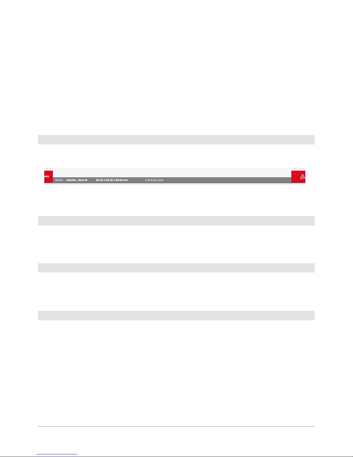
Here the model details (name, quantity, volume) and soft ware status are displayed.
In the .gcode preview mode, the status bar changes the information displayed as described later in a relevant chapter.
Pressing this button undoes most recent operations related to the models. If no operations on the solids were carried out
after the model was loaded, pressing the button will remove the .stl model loaded most recently. In the .gcode preview
mode, the but ton enables to return to the main sof tware inter face.
This is a graphic representation of the machine workspace. Printing outside the workspace is not possible, the sof tware
will not allow to print the models which extend beyond that space even partially. The models not situated in the workspace are highlighted red. The area changes dynamically in accordance to the printer you have selected.
The buttons enables selection of the machine and print its appropriate settings.
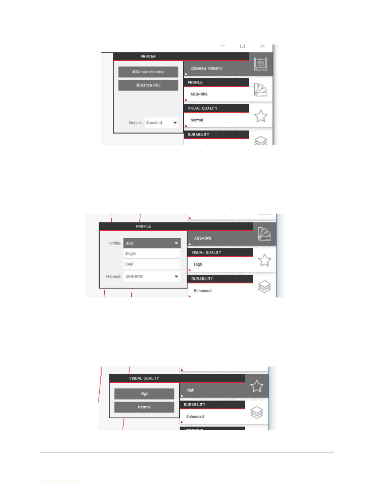
Printer: here you can select the printer that you would like to print the model on.
4.2 Status bar
4.3 Undo button
4.4 Vir tual workspace of the machine
4.5 Print prole selection buttons
Page 37
3DGence ONE | 37
version 1.0/08.2017
When you change the machine, the virtual workspace will adjust automatically.
Some printers have additional options (e.g. selection of nozzle diameter or printing module type). The selected settings
must comply with the actual machine status.
Prole: the options enables selection of the machine work mode (if available) and material to be used for the model.
The work modes (also known as Print Proles) enable to print using one or more print heads. The materials or combinations thereof depend on the selected machine and work mode. New materials are added by the producer on an ongoing
basis and are being published via software updates. To use the latest proles and full material base, we recommend ena-
bling automatic updates.
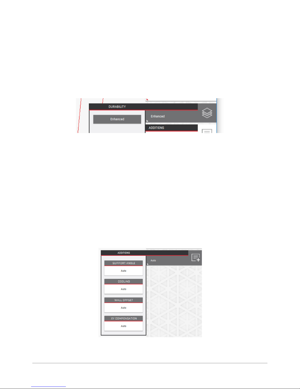
Visual Quality: enables the user to change the set tings related to the visual quality of models.
Page 38
38 | 3DGence ONE
The delivered predened settings have such options as layer height, print speed, work temperature, volume of ex truded
material per milimetre of path et c. se lec ted spec icall y to achie ve the requir ed res ult . The se lec table op tions in this men u
change dynamically depending on the selected material.
Greater visual quality will reduce the height of the printed layer and improve visual parameters of the printed model. This
will also signicantly increase the printing process duration.
Durability: enables the user to change the settings related to the durability of printed models.
The pre-dened settings delivered include such options as density, volume of extruded material per millimetre of path,
number of solid upper and lower layers in the model, print speed, tool temperature etc. selected specically to achieve
the required result. The selectable options in this menu change dynamically depending on the selected material and the
Visual Quality option.
Increased durability means more material will be used for the printout and the model will have higher overall strength.
It will be more susceptible to deformation related to material shrinkage and will have longer printing duration. The Solid
durability also may (although does not need to) affect the visual quality of the model adversely.
The same durability type for various materials may mean dif ferent actual durability values. For example, the same model
printed from Nylon with a lower durability set ting will still be more resilient than the ABS printout with the highest durabilit y setting as this is an inherent material property.
Additions: quick access to advanced options impacting the model size (offsets), the minimum overhang angle in relation
to the builplate to be used for the generating supports and cooling parameters. For most printouts this option should be
set to Auto.
Page 39
3DGence ONE | 39
version 1.0/08.2017
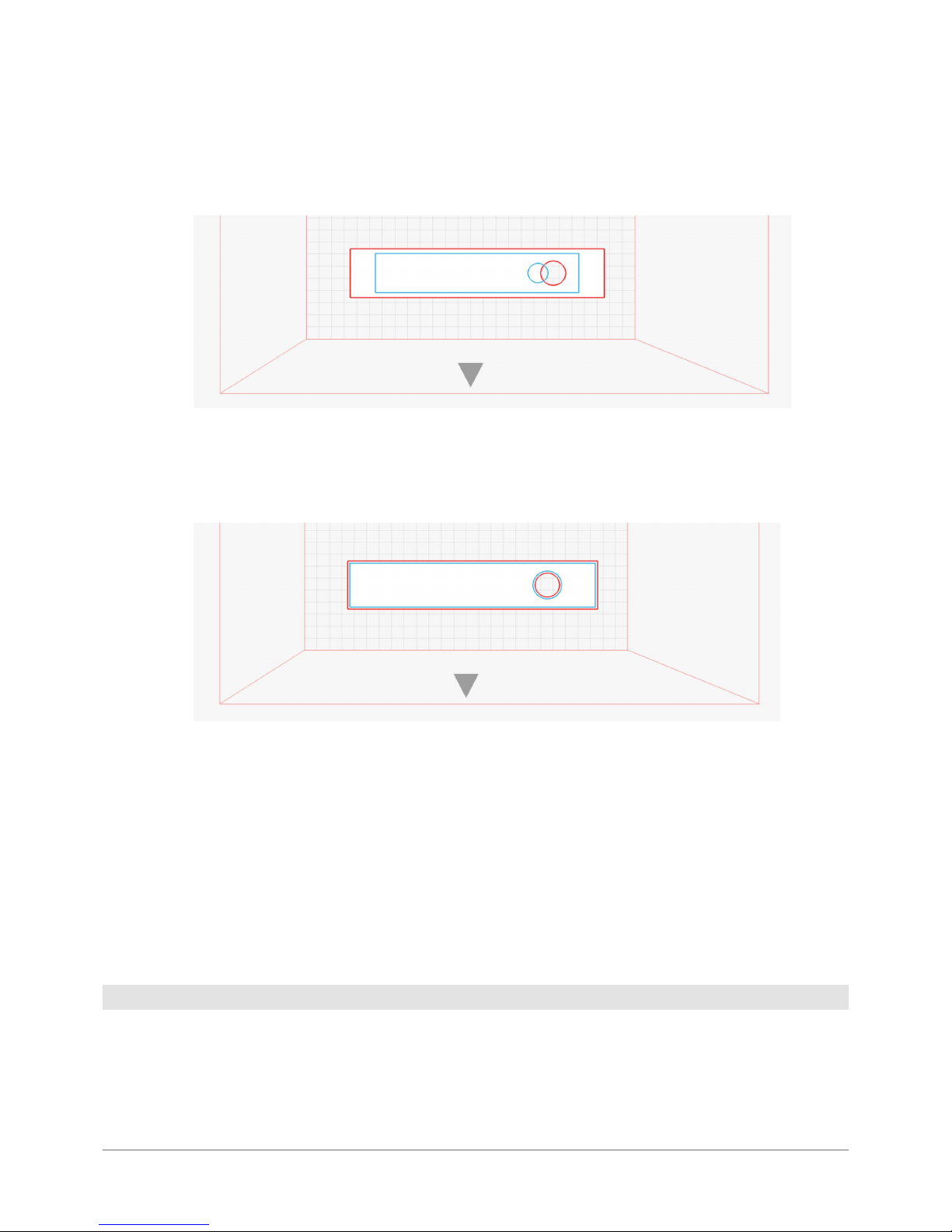
The XY Compensation option enables to change the size of the entire model in the XY plane in proportion to its size, after
generating .gcode. This gure presents the model loaded in the sof tware (red) and af ter 90% of fset has been applied
(blue). It is recommended to use offset to compensate for material shrinkage.
The Wall Offset option changes the model size, extending or narrowing its walls regardless of its size, af ter generating
.gcode. This gure presents the model loaded in the soft ware and after 3 mm offset has been applied. It is recommended
to improve the dimensional tolerance of the tted parts.
The Cooling option enables to set the printed model cooling manually. This value should be increased solely for printing
thin components which must be nicer visually and do not need to be strong.
The Support Angle option enables the user to set the minimum overhang angle for support generation manually. If the
model rests on a very small buildplate area, it may break off which is why this parameter should be decreased in such a
case. More supports mean longer printing time and more stable printout while fewer supports mean shorter printing time
and less print stability. Values “0” and “90” will disable supprt generation.
The Lighter Support option enables the user to force the support generation algorithm change. The Auto value leaves the
predened algorithm unchanged. The “On” option forces creation of lightweight supports while the “Off” one is used to
create heavier, more stable supports.
The graphic representation of the loaded model. The model can also be selected by left-clicking on it and, once selected,
it canbe modied. You can select only one model at a time. It is possible to print several models in one printing process.
They are printed simultaneously. However, it is recommended to print the models separately. This refers in particular to
larger, more complex and longer printouts. The intersecting models will be printed but with possible errors. The models
not tting the workspace will not be printed. Before printing, they should be divided into smaller par ts.
4.6 Loaded model
Page 40
40 | 3DGence ONE
The area in which the models to be printed can be arranged. It is recommended to print at the distance of at least 5 mm
from the workspace edge.
The side indicated by the arrow is the place where the physical front of the printer and operator panel is placed.
This displays the virtual printer axes.
Pressing this button will initialize the process of calculating machine paths (g-code) for selected print settings. The process progress bar will appear on the status bar. The solid appearance in the main software window will change to show
the graphic representation of movements. Af ter the work is completed, the software will enter the path preview mode to
display the paths to be carried out by the printer, as de-scribed in the subsequent chapter.
The solid appearance in the main software window shows the graphic representation of the printhead movements. This
view enables to preview the generated layers, verify print settings and save the .gcode executable le.
The model and print prole modication options are blocked. To change them, return to the main interface.
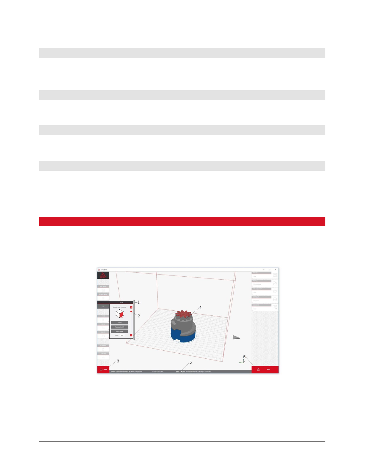
1. View options.
2. Previewing active model layer.
3. Return to the main inter face function.
4. Representation of anticipated material paths from .gcode le.
5. Status bar.
6. .gcode le saving button.
4.7 Virtual buildplate of the machine
4.8 Arrow indicating the physical front of the machine
4.9 Printer axis preview
4.10 Prepare to print button
5. PREVIEW MODE OF .gcode
Page 41
3DGence ONE | 41
version 1.0/08.2017
The options are identical as the ones in the main sof tware interface.
The slider enables the user to preview any layer of the active model.
In this mode the button is used for returning to the main interface. After returning, it will be possible to edit the model and
settings but before you continue you will have to prepare the .gcode le again using the Prepare to print button.
The model view in this mode enables to preview of the printout in the form of paths, arranged in the 3D printing process
for you particular model. The preview presents the entire model as a mesh and the last 3 layers as the simulated tool
paths. Using the active layer change option you can preview earlier model layers. Last layer is previewed by default.
• grey – the model,
• blue and black – supports,
• red – preview of selected layers.
The preview is used to check if the model will be printed correctly. For example, if the entire large model rests solely on
a few square millimetres of its base, it is likely to overturn in the course of printing. In such circumstancesyou should go
back to the main interface and increase the amount of supports generated.
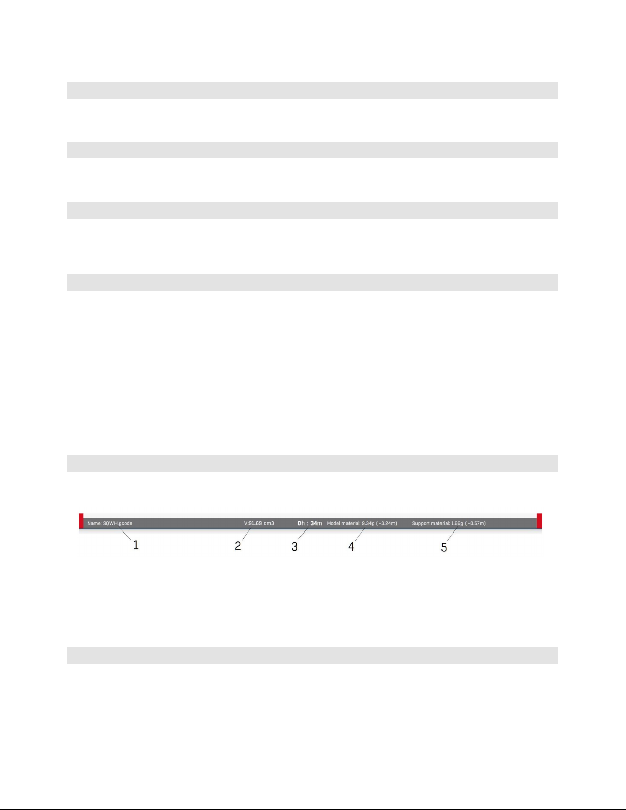
In this mode the status bar displays the following information:
1. Model name or the automatically generated name for a group of models.
2. Total model volume.
3. Anticipated printing duration.
4. Anticipated consumption of the model material.
5. Anticipated consumption of the support material.
This enables the user to save the model as .gcode executable le which will be used by the 3D printer. After you select
this but ton, a message will appear, allowing the user to choose location and a le name. If you use more than one model,
the name will be generated based on the current date and time.
5.1 View options
5.2 Options for previewing layers
5.3 Undo button
5.4 .gcode le preview
5.5 Status bar
5.6 File saving button
Page 42
42 | 3DGence ONE
The advanced users may modify the advanced print settings. This option is designed to allow the user to modif y the exist-
ing print proles in order to improve the print quality for materials not certied by the producer or to adjust the machine
settings in order to achieve the presumed result (e.g. increased strength of the side walls).
3DGence Slicer uses a modied CuraEngine engine, preserving parameter names thanks to which experienced users
may use comprehensive documentation of Cura software community. The function names and operation are identical as
in the Cura software. The proles for the Cura soft ware are not compatible with 3DGence Slicer proles as the software
operates in a different way but they can be rewritten using the prole edition option.
The advanced proles are not co nnected with the ofcial proles hardcoded in the so f t w are as the sof t war e use s the ir cop-
ies to process changes. Thanks to that it is not possible to damage the ofcial proles accidentally and they are always
accessible from the standard software interface level.
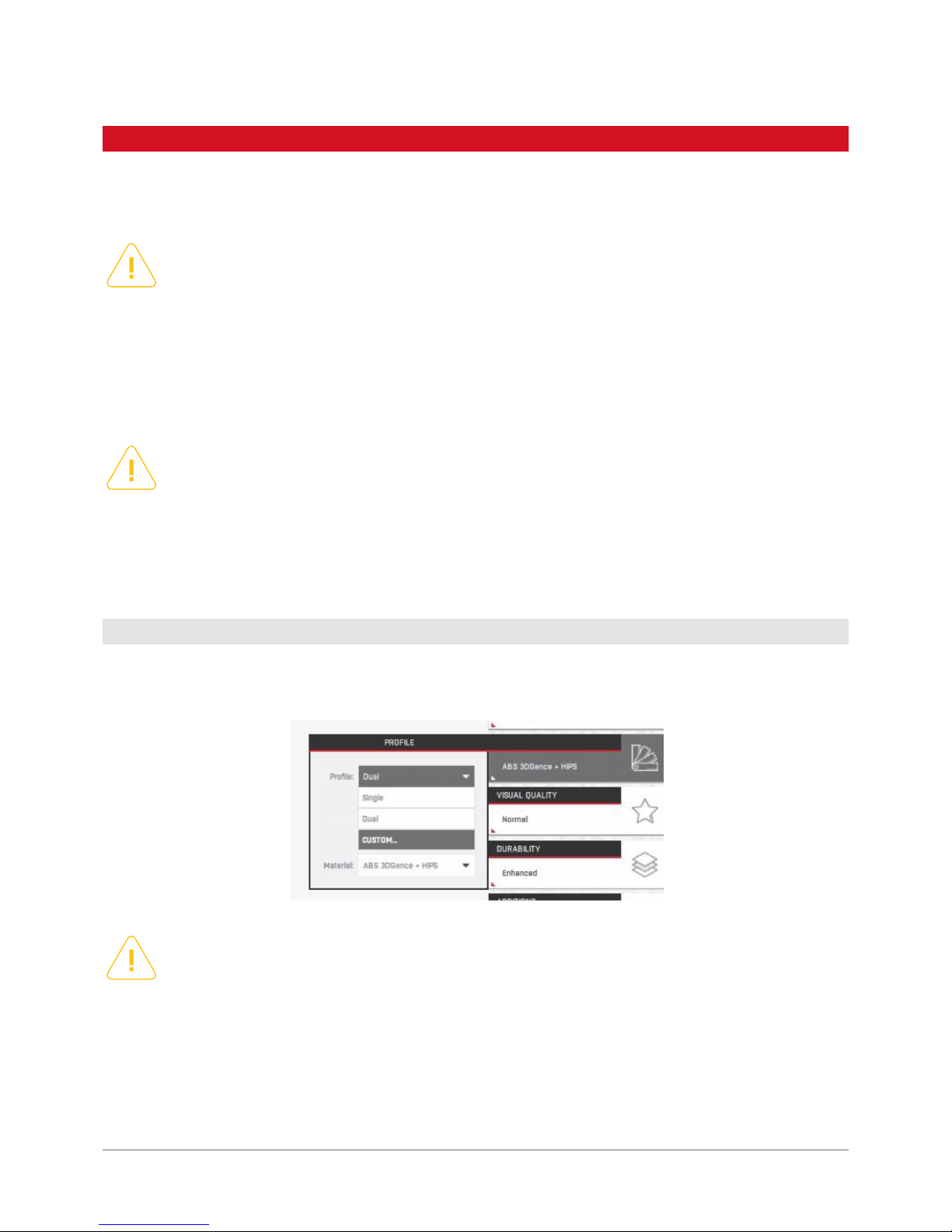
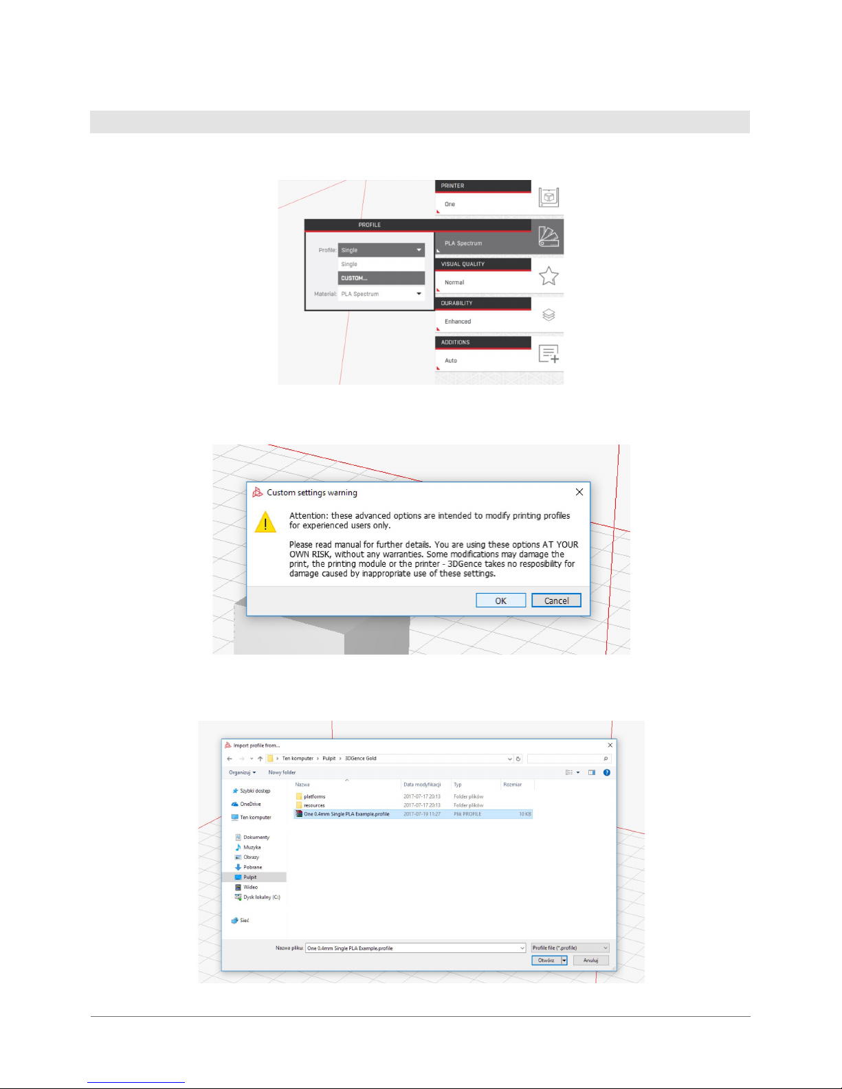
The access to advanced settings takes place by selecting the Custom Prole in the Proles option. The sof tware will
display the message pointing out the hazards and will enable to load the advanced options.
The currently loaded advanced prole is displayed on the status bar.
Please remember that using any materials and printsettings not provided by the producer makes the user fully
liable. The producer shall not be held liable for any failures resulting from such activities especially with respect
to the printhead and material guiding system. The producer discourages from using printing materials which
may damage the nozzle (e.g. the ones containing glass or carbon bre) or clog it (materials with insufciently
ground additives, e.g. wood).
Please note that for technical reasons the setting combinations in material proles were disabled. This means
that e.g. when you change the Line Width parameter, the parameters in the Wall Line Width having priority
over the original setting will not be changed. If you over write the ofcial prole copy or damage the prole
with incorrect settings, you can download the original advanced proleversions from the producer’s website.
6.1 Access to advanced settings
The printer selected in the printer settings is not important as the advanced prole contain such information.
Please note that forcing the initialization of the .gcode operation prepared for inappropriate device may damage
the machine and is not covered by the guarantee. After you have selected the non-standard proles, other
print setting options are disabled. Selecting other print settings in the Additions options will overwrite the
information in the prole.
6. ADVANCED SETTINGS
Page 43
3DGence ONE | 43
version 1.0/08.2017
6.2 Setting edition window
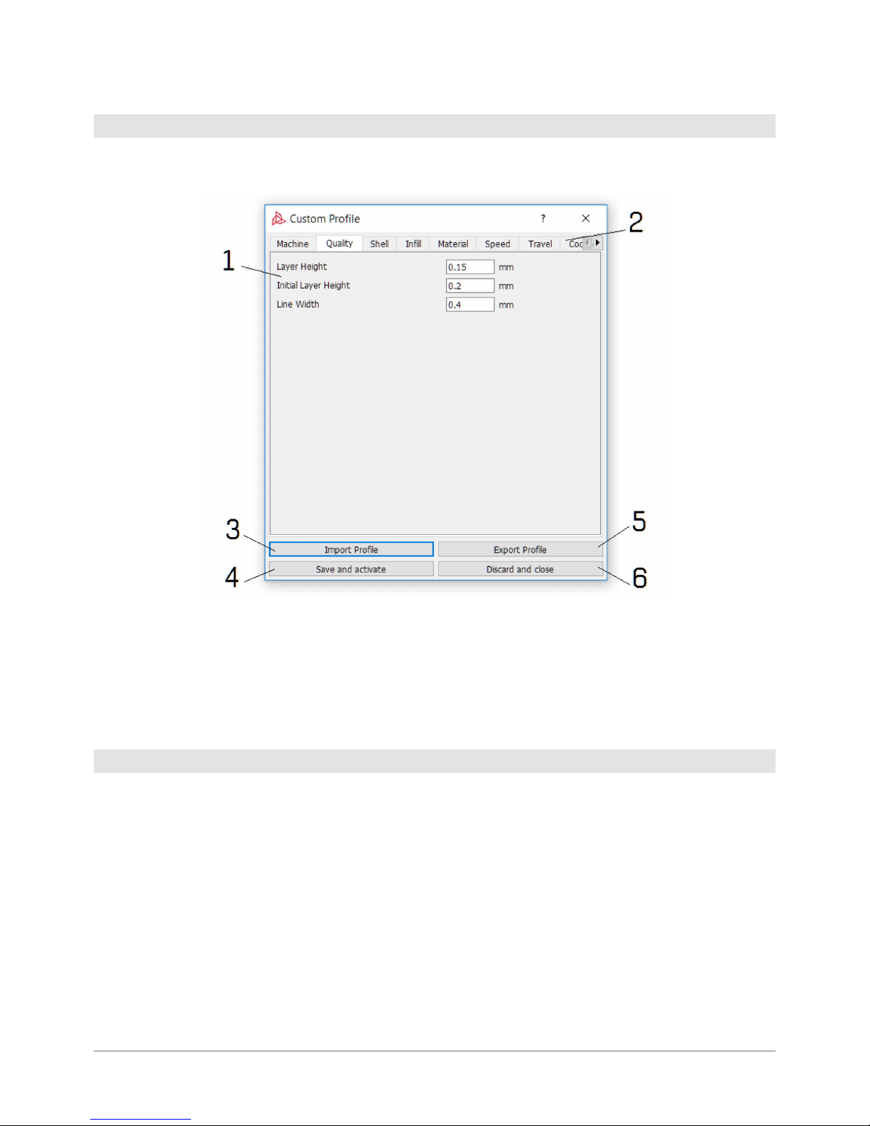
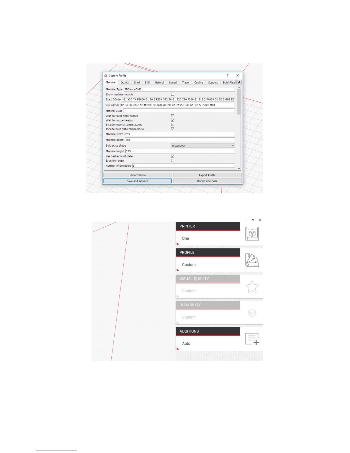
After you have selected the Custom Prole, a window displays where you can modif y the settings.
1. Setting edition window.
2. Pages where you can change the settings.
3. Prole import, the window opens up automatically during start-up.
4. Prole saving and activation, window closure.
5. Prole export.
6. Change cancellation, no prole activation, window closure.
The Print Proles obtained by modif ying advanced settings may be shared freely. Please note that the proles created by
means of different software versions may not be compatible. In such circumstances, please verif y the print set tings as
this may entail the risk of machine damage or print quality deterioration.
The proles may be shared also with the producer via the ser vice request form. If the user has created a prole for any
non-certied material, the activities aimed at cer tifying such a material will be initiated to incorporate it with of cial
proles. If the user has improved the quality of printing on the material, the producer will also initiate activities to update
the of cial proles to include such changes.
6.3 Prole sharing
Page 44
44 | 3DGence ONE
6.4 Advanced proles step-by-step
1. Select „Custom” prole from the prole list.
2. Conrm the threat warning message.
3. Select your advanced setup le. Make sure the prole is prepared for the printer you own.
Page 45
3DGence ONE | 45
version 1.0/08.2017
4. Settings edition window will appear. To save and activate press „Save and Activate”.
5. Activating the Custom prole will prevent you from changing predened print quality settings.
6. Prepare your le with the „Prepare to print” button.
Page 46
46 | 3DGence ONE
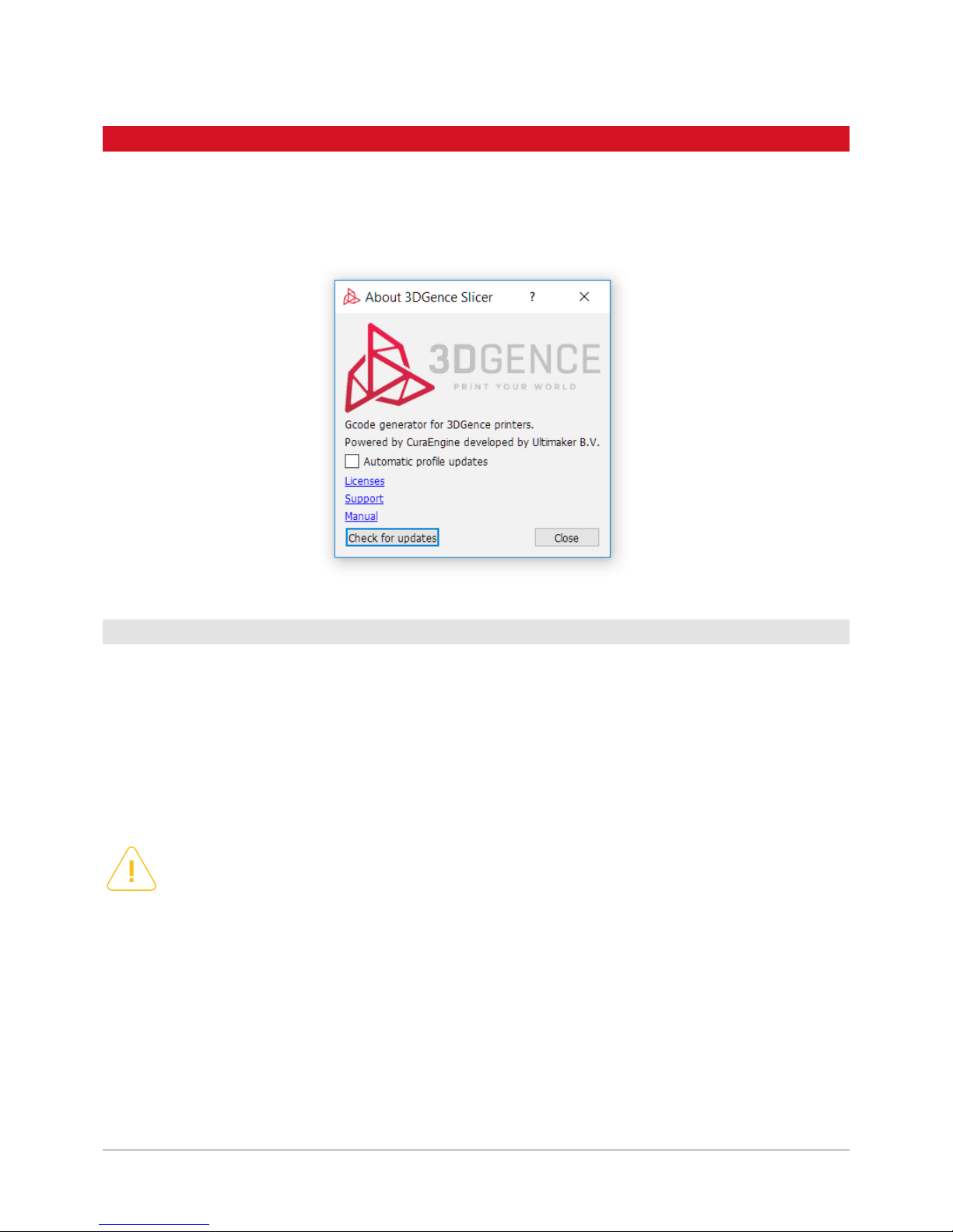
Under 3DGence button, you can nd the software information, direct link to the producer’s technical support, licence
information, ability to download the latest print proles manually and the ability to enable or disable automatic updates
of the print proles.
The recommended way to obtain any support related to the sof tware and print quality is to use the link under 3DGence button in the top lef t corner of the software window.
The producer guarantees the highest possible quality of models produced with the dedicated sof tware and materials.
If the user detects any defects of the produced model or soft ware errors when using the software, please contact us by
e-mail and at tach a photo and description of such a defect and, whenever possible, a .gcode and .stl le. Every model
submitted to the manufacturer in this way will be assessed and/or printed in the company’s headquaters. The producer
will suggest a problem solution, advice, start maintenance activities (whenever required), prepare an error-free .gcode
executable le or updatie print proles.
If the user needs any se t tings for a specic ma terial or any other qualit y settings, the y ma y request them using the technical suppor t form. If the user created an initial prole corresponding to their needs, they can submit it to the producer
using the same form, who will take measures to introduce it as an ofcial prole.
The producer does not provide support for advanced proles.
7.1 Support
Please remember that using any materials and print settings not provided by the producer makes the user fully
liable. The producer shall not be held liable for any failures resulting from such activities especially with respect
to the printhead and material feeding system. The producer discourages from using printing materials which
may damage the nozzle (e.g. the ones containing glass or carbon bre) or clog it (materials with insufciently
ground additives, e.g. wood).
7. SUPPORT AND UPDATES
Page 47
3DGence ONE | 47
version 1.0/08.2017
7.2 Updating print proles
The automatic updates are a service which enables the sof tware to automatically load the latest print proles (machine
settings and materials), provided ofcially by the producer. The software checks for updates after each start-up, provided
the user agreed to have the updates on. They can be enabled by pressing the button with the producer’s logo in the top left
corner of the inter face and selecting the relevant option. The software itself needs to be updated manually.
When you disable the automatic updates, this will block software contact with any ex ternal servers without any explicit request from the user. The updates require active connection with the producer’s servers, granted by the operating system
to the software.
Automatic updates do not affect the existing advanced proles, though they load additional les to the editable prole director y. Those are descr ibed with a date. To use older proles, activate the proles with relevant dates by means of advanced
options “Custom Prole”. Any legacy and experimental proles are available on the producer’s website.
3DGence Slicer soft ware updates should be installed manually, using the installer le available on the producers website.
With the enabled automatic updates of the print proles, the software checks for any new version upon each boot-up. On
the same station, several soft ware versions may be installed simultaneously with no adverse effects.
The print prole updates are always going to be published for the latest sof t ware version.
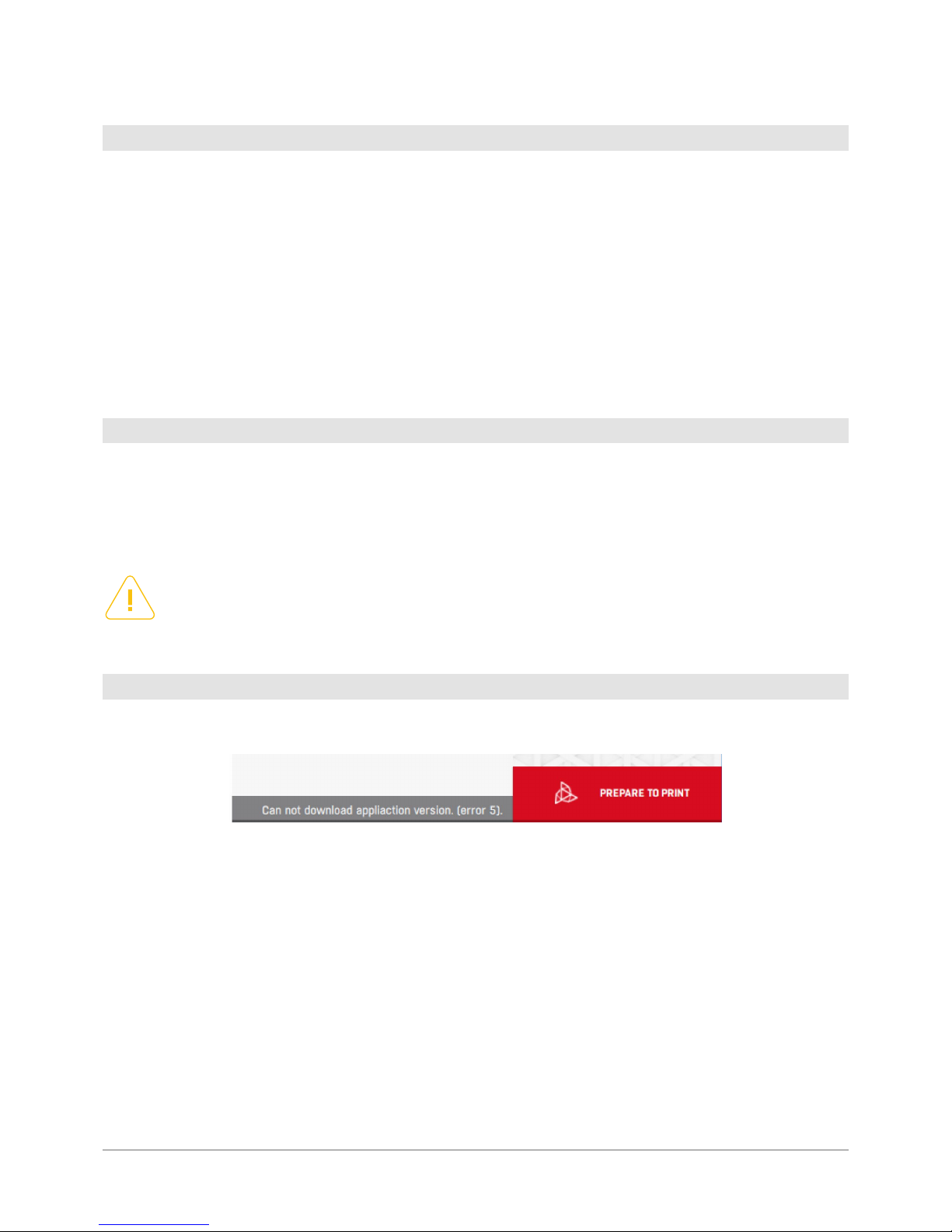
The update status appears on the progress bar immediately after the sof t ware is started, beside the Prepare to print button.
Checking for updates...: the software checks for any available updates. You can work as usual.
Newest proles loaded: the sof t ware uses the newest material proles available.
New prole downloaded: restart program to update: The sof tware updated the proles, restart it to load them.
Prole updates disabled: automatic updates are disabled and no attempt at checking for prole availability has been made.
New version available: a so f t w are update is available which needs to be downlo aded and inst alled manuall y. Pro le updates
have not been downloaded as they require a new software version.
Error: failure when downloading print proles. The number in the bracket is the update error code. For example the message:
Cannot download application version (error 5) means the error of software communication with the ser ver.
7.3 Software update
Please note that although the producer makes ever y effort to ensure any advanced proles created by users
are compatible with the latest soft ware versions, always verif y the print settings following any update as this
may bring about the risk of damaging the machine or compromising the print quality, as well as intruducing
new functionalities not supported by older versions
7.4 Update statuses
Page 48
48 | 3DGence ONE
VI POST-PRINTING OPERATIONS
1. REMOVING THE PRINTOUT FROM THE DEVICE
The cooling sequence starts immediately after nishing the printing process. The work eld of the printer
remains highlighted in red until the temperature is safe for removing the printout from the work table. Except
the color of highlighting while the device cools down, information on cooling progress is displayed on the
printer’s panel. When the temperature of printer is safe, the device lighting turns green and the panel displays
message Remove Model.
Always wear protective gloves when removing the printed object from the work table!
NOTE:
The cooling sequence can be skipped af ter nishing printing. To do this select, the option Skip Cooling from the
printer’s menu. However, only experienced operators are allowed to use this option. To prevent accidental burns,
make sure that the printing head is cooled down and withdrawn to zero position of X-axis (maximum left).
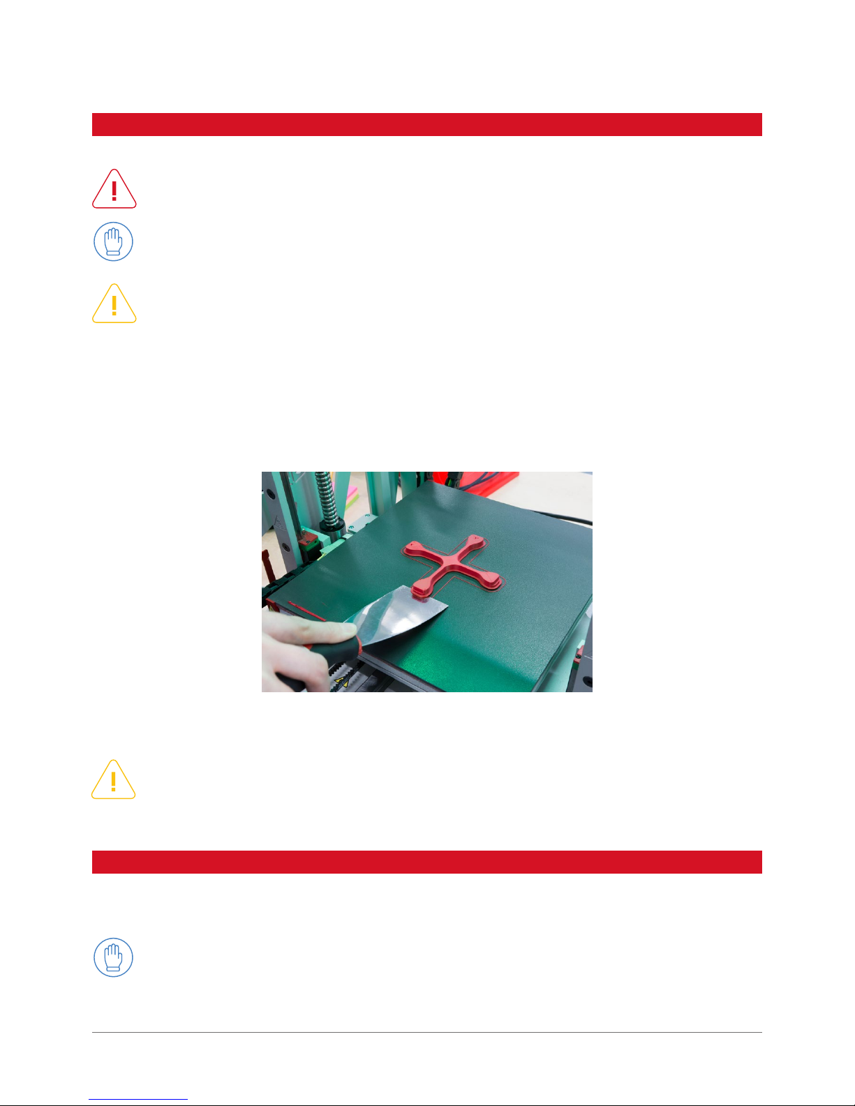
To remove the printout from the table, use the attached spatula to gently pry the object up from several sides. Never use sharp
co r ners of spatul a – us e onl y the at edge of the to ol (g. 34). Ne v er rem o v e the pr intou t by force , as th is may dama ge th e work
table. In case of problems with separating the printout from the table, it is recommended to reheat the work table and cool it
down again. Reheating the table can be repeated several times and may prove necessary for solids with large sur face base,
the base of printout should be constantly pried up with a spatula when the device is cooled.
WARNING:
Do not touch the table surface with bare hands! Any undesired substance spread on the sur face of work table
may affect its adhesive/adherent proper ties necessary for the correct printing process. Always use CLEAN
protective gloves to ensure that printed objects shall properly adhere to the table.
2. CLEANING
2.1. Cleaning the print head
Cleaning the print head is recommended each time after nishing printing for the purpose of removing any remains of molten/burned material stuck to the outer surface of the nozzle (Figure 11, element 26).
Fig. 34. Printout removal procedure.
Page 49
3DGence ONE | 49
version 1.0/08.2017
For this purpose:
1. Wear protective gloves.
2. Fr o m the pr i n t e r ’s menu ac t i v a t e Preheat PL A /Pr eheat AB S - depen d ing on th e material used in the noz zle . Caution! Work ing
table also heats up within this option.
3. Secure good access to the head. Use options Prepare → Park Heatbed → Middle or Bottom.
4. Gently remove the molten/burnt remains of material using non-combustible cloth, metal spatula or tweezers.
5. Turn off the heating after cleaning the head ( To do this, use e.g. Cooldown function from printer’s menu.
2.2. Cleaning work table
A dirty or greasy surface of work table can seriously impair or make impossible the printing process. It is
recommended to clean the working table before each new printing.
The work table should be cleaned according to the instruction below:
1. Turn of f all heating elements and wait until they are completely cooled down. Use “Cooldown” option from the menu.
2. Turn the device off by pressing the power button and unplug the printer from the power source.
3. Wear protective gloves.
4. Use the spatula to clean the surface of the work table from any residual material. Then moisten a cotton cloth (not synthetic)
with the following type of solvent cleaners:
• 10% solution of spirit vinegar
• acetone
• nitro
• petroleum cleaner
When degreasing the table, pay special attention to avoid spreading solvent cleaners on any plastic and painted elements
of the printer as it can damage them.
5. Wait until the solvent cleaner evaporates.
WARNING:
Always read and observe safet y instructions on solvent containers - solvent fumes may be harmful.
3. SWITCHING OFF PRINTER
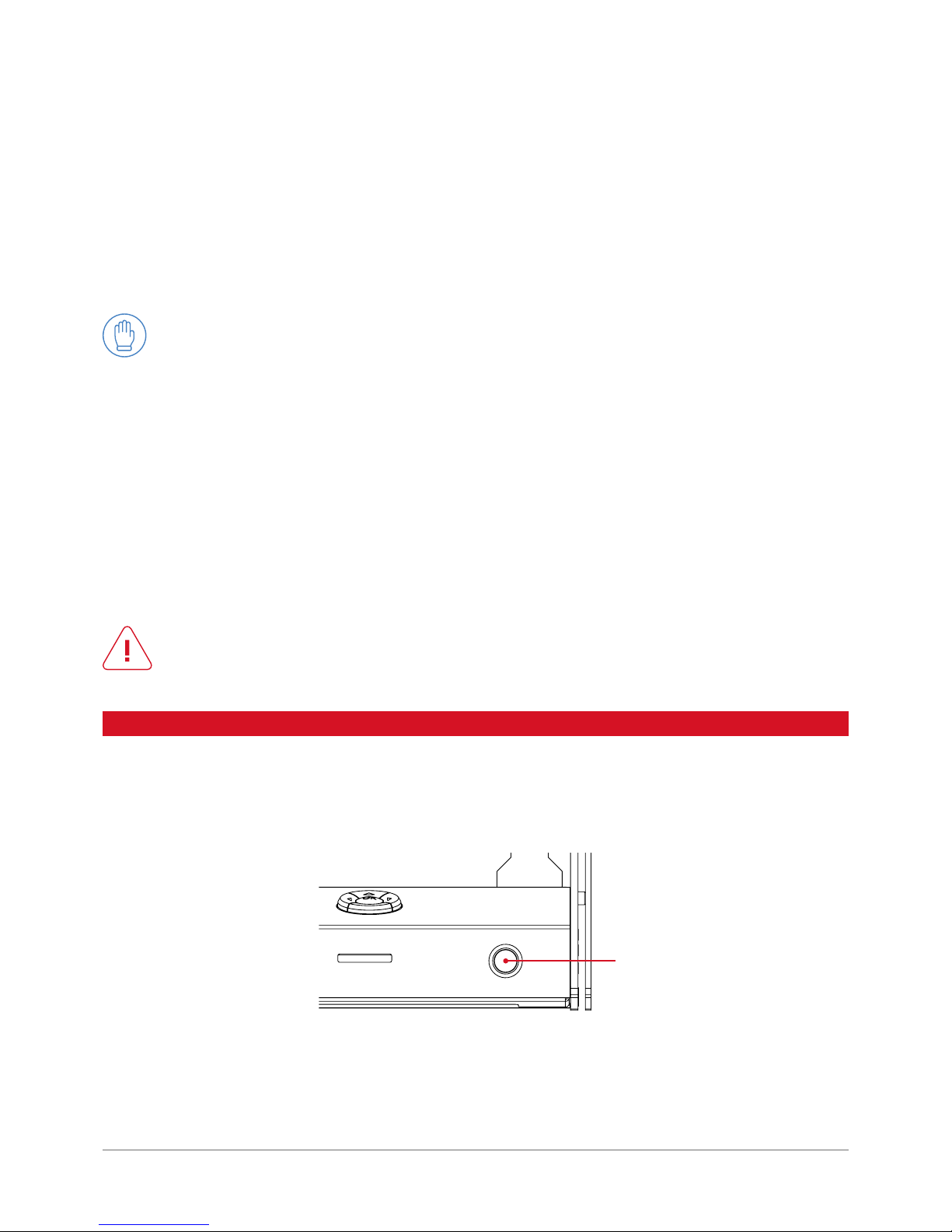
To turn off the printer, press POWER button on the right side of the front main panel of the printer (g. 35).
1
Fig. 35. Location of POWER (1).
Page 50

50 | 3DGence ONE
After switching of f the device the lament should be protected against humidit y, dust and other soilings. When not using
the printer for a long of time it is recommended to secure all axis guides and ball screws against dust and other soiling.
When the device is switched of f:
• never leave the printer in a humid room
• never leave the printer in a dusty room
• never place the printer on high shelves
• never place the printer in a cardboard box, bag or closet before the device heaters are completely cooled down
• place the printer out of reach of children
• protect the lament and the device against humidity, dust and other soiling
• when storing, disconnect power cable from the device
WARNING:
Never turn off 3DGence ONE printer by pulling the power cable from the socket. This can damage the device.
Page 51
3DGence ONE | 51
version 1.0/08.2017
VII HEAD REPLACEMENT
3DGence ONE printer is equipped with a quick, patented system of printing head replacement - Push-System.
It enables high-speed printing with the use of large diameter nozzle or high precision printing requiring nozzles with smaller diameter. As a standard, the printer is equipped with the nozzle with 0.4 mm diameter. Other
nozzles available for the printer have the diameter of 0.5 and 0.3 mm.
To replace the print head:
1. Complete the full procedure for lament removal. Printing head must be clean. (see p. Removing lament)
2. Got to Prepare menu, select Hotend Change and follow the instructions on printer ’s LCD panel:
a) wait until the print head cools down.
b) turn the printer off using power button.
3. Wear protective gloves.
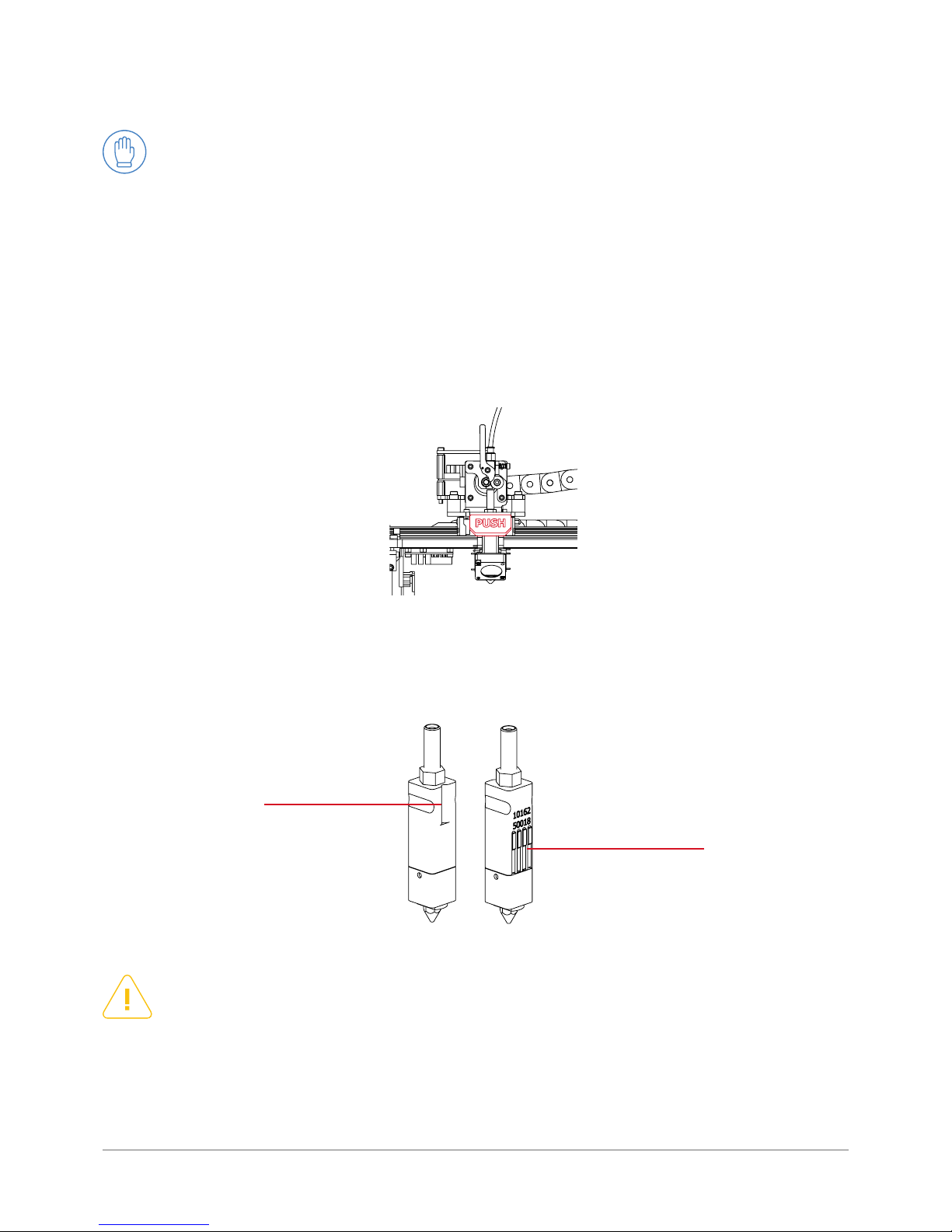
4. Move the print head along X axis to the maximum left to immobilize it for the time of replacement. Fully press down and
hold the red PUSH button (g. 36). Slide the head out with the other hand. Pay special attention not to drop the head on the
work table.
5. At the exact place of the old one, insert the new, clean printing head. The cavity marked on the drawing must face your direction
(towards the front of the printer) (g. 37 ). The PUSH key must remain pressed - other wise the head can be inser ted incorrectly.
NOTE:
Pay special attention while mounting printer’s head. To avoid bending contact pins, hold the print head in an
upright position. In the event of damaging contact pins or incorrect insertion of printing head, the switched on
printer displays an error message „def (see - ADD)” in temperature parameters window.
6. When the head is properly mounted in the blocking mechanism, release PUSH but ton to lock it.
7. Print head replacement is nished. Press POWER button to run the printer. Always remember to dene the nozzle type in
the program.
Fig. 36. Location of PUSH button.
Fig. 37. Location of the cavity.
contacts
groove
Page 52
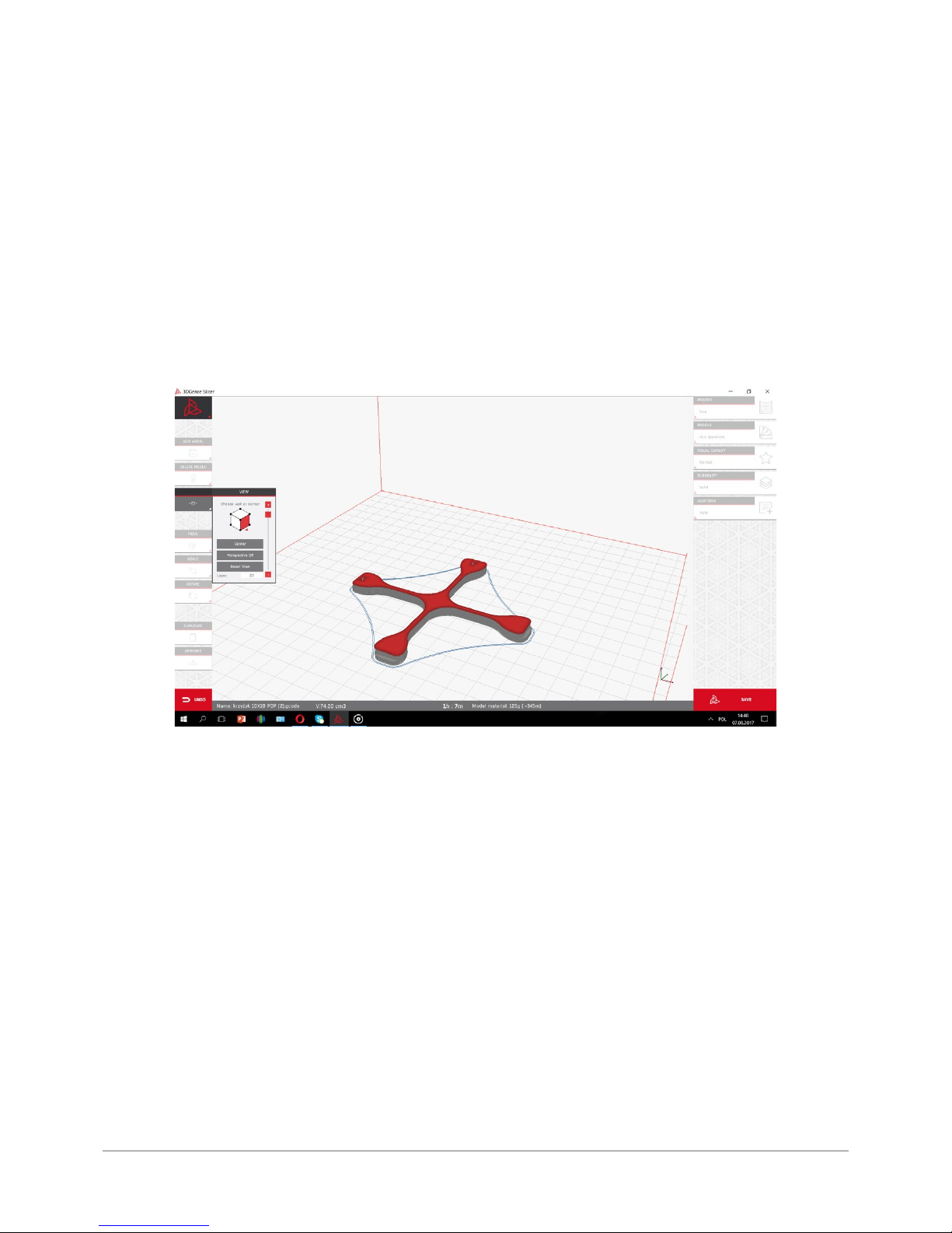
52 | 3DGence ONE
VIII CALIBRATION OF AXES
3DGence ONE printer has a unique system for precise adjustment of size parameters of the printed object. The printer
is pre-calibrated for 3DGence PLA material with an accuracy of 0.1 mm. Printing with the use of materials with different thermal contraction may require size correction of a printed object. For most printers, such correction can be ver y
dif cult or even impossib le. With its inn ova tive system, 3DGenc e ONE allows quick, easy and accu rat e siz e cor r ect ion.
The new system performs only one printout calibration session and a simple measurement to acquire the accuracy of
0.02 mm.
NO T E: Each type of ma teria l used as lam ent ha s it s ow n thermal cont r action. To maxim ize the pr ecis ion of th e re sul t s ,
the calibration should be made for the exact material that is to be used for printing.
To perform a precise calibration of X and Y axes, it is necessary to make a print of a special object. Calibration le is on
SD memory card – CalibrationXY_1h45min.gcode. The printing of calibration object takes about 1 hour and 45 minutes.
After printing, cooling and careful removal of calibration object (the cross), take measures of X and Y axes of the print-
ed model. Several measuring tools can be used, provided that their accuracy cannot be worse than 0.05mm:
• caliper,
• micrometer,
• coordinate-measuring machine,
• optical devices.
The printout should be measured along X and Y axis. For reliable measurement, use the following guidelines:
• the measuring point should be in the middle of the height of the printed object, both points at the height of the
same layer;
• repeat the measurement for X and Y axis 5 times. Discard the highest and lowest results from each group. Average
the results for both axes:
Page 53
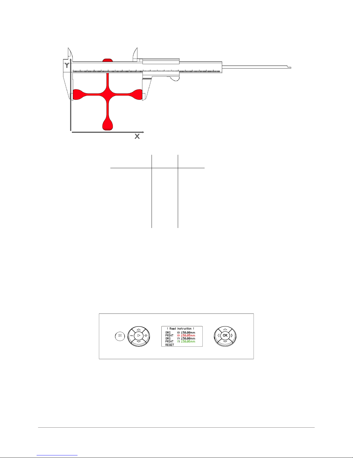
3DGence ONE | 53
version 1.0/08.2017
MEASUREMENT: X Y
150,08
150,06
150,05
150,04
150,05
150,05
150,07
150,06
150,08
150,06
150,05
150,06AVERAGE:
The result of this formula will be the basis for further operations:
1. Go to Calibration menu and select XY Calibration. Conrm selection by pressing OK button.
2. Use up and down buttons from the right panel to select Print X value and press OK. Use up and down buttons to introduce
the value obtained from X axis measurements.
3. Use up and down buttons from the right panel to select Print Y value and press OK. Use up and down buttons to introduce
the value obtained from Y axis measurements.
4. After entering all values, conrm changes by selecting „CALCULATE & SAVE”. The algorithm will calculate printing parame-
ters according to the measurements made.
Due to this procedure, the next printout from the material, for which the calibration was made, will be completed with the
compensation for thermal contraction of the material in X and Y axes.
Page 54
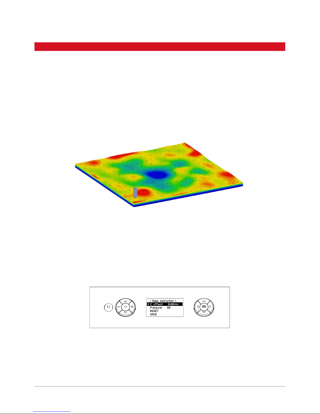
54 | 3DGence ONE
Each device undergoes manufacturer’s default scan of the work table. For ensuring optimal printing qualit y, it is recommended to repeat the scan procedure every several hundred working hours of the printer. It is also recommended
to repeat the scan procedure in case of adhesion problems or uneven application of material while printing rst layers.
3DGence ONE printer is equipped with advanced algorithms for autocalibration and autocompensation of the work eld.
Scanning the table is required for proper autocompensation of printing process.
Autocalibration of work eld is based on measurements of ex truder ’s pressure sensor examining the surface of work
table in approx. 300 points. Based on the obtained measures, the program creates a virtual map of heatbed curvature,
which is the basis for autocalibration and autocompensation of printing process (g. 38). Table curvature map is stored
in the printer’s memory and can be changed only af ter the nex t scanning of the table.
Autocompensation of the work eld consists of single point measurement of the distance to the work eld and setting the
correct distance for starting printing operation. Autocompensation process is performed each time before printing. After
setting the correct height over the chosen single point, the printing operation is per formed pursuant to table cur vature
coordinates (curvature map) stored in printer’s memor y for the purpose of real time adjustment of nozzle height in Z axis
to maintain the exact same height of the nozzle over any chosen point on the surface of work table.
Autocompensation settings can be changed from „Calibration” menu by selecting „Autocomp. settings”.
Z offset: Manual correction of Z-axis measurement allows adding (or subtracting) a given value to Z axis single point
measure (autocompensation). If Z offset is set to 0.1mm, the initial height of printing will be lifted by this value:
Height of the rst layer 0.2 mm + Z-offset: 0.1 mm = actual printing height: 0.3 mm
IX MAINTENANCE AND SERVICE ACTIVITIES
1. AUTOCOMPENSATION
Fig. 38. Virtual map of heatbed curvature.
Page 55
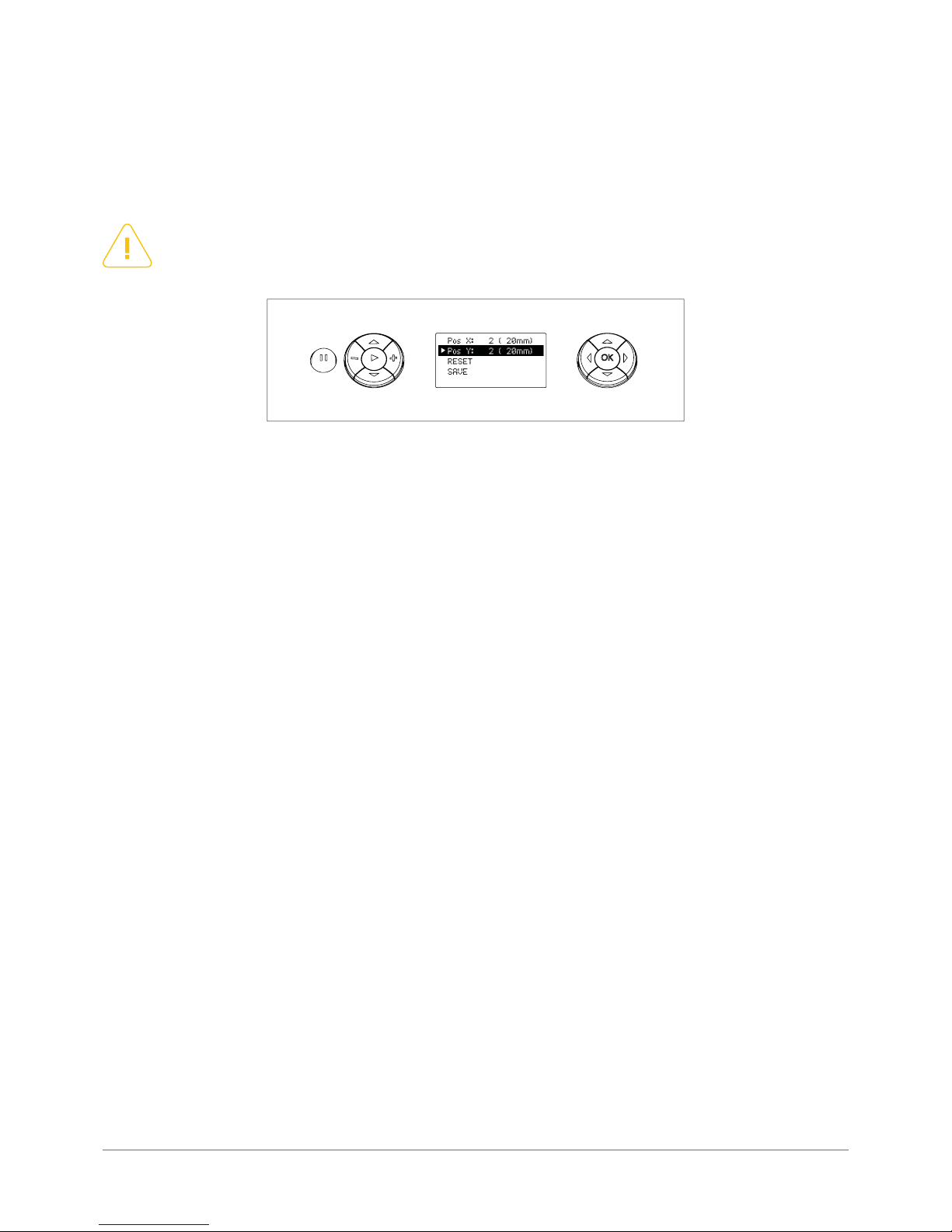
3DGence ONE | 55
version 1.0/08.2017
NOTE:
Negative values of Z offset should never exceed the thickness of rst printing layer!
Pressure: Sensitivity of autocompensation measurement on Z-axis allows determining the value of contact force for print
head while measuring the height bet ween the head and the work table. Measurement sensitivity can be adjusted in the
range between 20 (0.5g) and 120 (4g). When using materials with higher uidity, it may be necessary to increase the
contact force to reduce the risk of incorrect measurement caused by leaning of the head against the ex truding material.
When starting the print, these incorrect readings may cause lif ting up of the head as a result of adding the thickness of
material leaking under the head (holding the head up) in the process of height calculation.
Position of measurement is another important parameter in the process of autocompensation. This parameter can be
regulated by selecting Probe position in Calibration main menu.
By editing values in Pos X and Pos Y, the point of autocompensation can be changed - respectively for X and Y axes of
the printer.
This option can be useful when using adhesive tapes or pads. In such a case, Z-of fset should be set to correspond to the
thickness of the applied tape or pad. This parameter can be also set to negative values and as a result, the starting point
for the printout will be placed at a lower height (closer to the table).
Page 56

56 | 3DGence ONE
X DICTIONARY
ABS – (poly acrylonitrile butadiene styrene) – apart from PLA one of the main materials for 3D printers. Features a high impact
strength, hardness and resistance to scratching. It is not resistant to UV radiation. Soluble in acetone, which allows for post-processing of prints by using the acetone vaporizing method. ABS prints can also be glued together with ABS solved in acetone.
ABS features a fairly signi cant thermal shrinkage (up to 0.7%). The typical operating temperature for ABS is 220 to 250 degrees
Celsius and about 100 degrees for the bed. The heated working space is necessary to maintain dimensional compatibility for
printed items.
Adhesion – in the 3D print con t ext it means th e adhes ion to th e dev ice bed. Insuf cient pr int adhesio n ca n res ult in par t ial or com-
plete tear of the print from the table during printer operation. The ceramic table of the 3DGence ONE provides a good adhesion for
the certied materials, however for hard to print plastics there is a lot of commercial solutions available for improving adhesion
of the print to the bed. Grease or soiling on the table has a negative impact on adhesion.
Autocalibration – a printer capacit y to perform an automated bed calibration. This process is designed to generate curve and
irregularity maps for the working table and by introducing dynamic corrections it provides a constant height of the nozzle over
the bed. It usually takes from a few to several dozen minutes, and necessar y user operations are reduced to starting the process
by using an appropriate command.
Autocompensation – consists in a single-point measurement of the distance to bed and determining a correct distance to start
a job. This process takes place each time before printing. After set ting a correct height over a single point, further part of the
print will be performed by taking into account the table curve pattern stored in the printer memory – thanks to this, the distance
between the nozzle and working table is always the same and corrected in Z axis on a continuous basis.
Bridge – a part of model printed in the air, suspended between two par ts of the print. It is subject to special calculations while
preparing the le for printing, If the bridge is too long, it may be subject to deformation. In such cases this component should be
supported with support structures.
Brim – one of the methods of improving print adhesion to the bed. It consists in increasing the adhesion sur face to the bed by
generating additional, external brims of the solid at the level of the rst layer of the print. The more brim lines will be added, the
larger will be the adhesion surface. Typically, from 5 to 20 brim lines are used. The brim should be used, in case of problems with
detaching prints from the bed.
CAD (Computer Aided Design) – collective term for various computer aided design processes. The CAD methodology is used in
mechanical, electrical, medical and architectural engineering. The base for CAD methodology is geometrical modeling aimed at
creating two or three-dimensional representation of the planned component. There are various CAD software packages availa-
ble, adjusted to users’ needs and requirements. From those programs models in STL or OBJ formats are exported for use in 3D
printing. The most popular CAD packages include: SolidWorks, Inventor, PTC Creo, CATIA, Rhino, SolidEdge – however there many
others.
Curling – a negative phenomenon that occurs during 3D print using FFF technique. Curling can be observed while printing
overhangs or sharp edges between faces of a solid. It manifests as curling of the print edges upwards. In extreme situations it
may lead to print failure, and always have a negative impact on visual effect, especially at the bot tom parts of the print. It leads
also to collisions of the printing head with the print during operation. The basis method of ghting against curling is the active
print cooling. If turning on the fans does not help, it is good to lower the speed of printing.
Slicing – the process aimed at generating paths and instructions for the printer (machine code, G code) from a 3D model. At the
level of slicer we can choose such set tings as layer thickness, print speed, lling density, thickness of solid walls or nozzle and
printing bed temperature. In addition, it is also possible to select the use and the densit y of supports and one of the few ways of
improving the print adhesion to the bed (e.g. raft or brim). The 3DGence ONE printer uses the 3DGence Slicer program with prede-
ned settings from various materials and resolutions. The nal effect of slicer operation results in obtaining a machine code representing a specic 3D model in the for m of G code (g- code, *.GCODE) that is subjec t to inter pre tat ion by the prin ter electronics.
Nozzle – a head component coming into direct contact with the print. The nozzle heated to temperature specic for a material
makes it ow and forms a thread of plastic with a rated nozzle diameter. The 3DGence ONE printer as standard is equipped with
a 0.4 mm nozzle. The nozzle outlet diameter affects the available resolutions, print speed and accuracy.
Page 57

3DGence ONE | 57
version 1.0/08.2017
Extruder – a part of the 3D printer working in the FFF technology. It is designed to feed the lament at a strictly dened rate,
and consequently – quantit y. The 3DGence ONE printer is tted with a Bowden type extruder. It means that extruder motors
are located beyond the moving printer parts, leading material to the head via the PTFE tubing. It makes the design lighter and
has a positive impact on the print quality.
Endstop – an optoelectronic switch that limits a 3D printer movement beyond the maximum range. The device is tted with
3 optical endstops – one for each axis. The optical endstop does not require any physical contact with the corresponding
interrupter, which provides its long life, however one should notice that it is sensitive to the sources of bright light which may
result in triggering its false operation.
Filament – popular description for material used to print in fused deposition modeling (FFF) technology. The lament is a ther-
moplastic wire (PLA, ABS, PVA, HIPS, PC, N ylon or other) generated with specic tolerances The lamen t is wound on a spool.
The relevant parameters when selecting a lament include: dimensional tolerance and the method for protection against moisture (optimally the lament should be vacuum packed with a moisture absorber.) A high diameter of the spool hub provides
an opportunity to use its entire length – an excessive bending of the lament (e.g. on a small spool hub) can cause problems
with its application. The lament after opening the package should be stored in a dark, dry place with a moisture absorber.
G-Code – is a normalized programming language adjusted to control CAM machines. In simple words, the G code string inc-
ludes machine instructions – in what direction, how fast and along which axis to move. The code for printers is generated by
slicing software (slicers). It stores all the data on subassembly temperatures and the revs of motors in a precision sequence
that results in moving the head and denes the extruder behavior. The code commands are sent line by line to the printer
controller processor during the printing process. The processor interprets the code based on its sof tware and sends specic
signals to particular components.
Skipping steps – under abnormal motor and controller operating conditions (e.g. too high temperature, mechanical resistance)
the motor can skip operation steps. This can be noticed after moving the printing plane in the axis in which the motor skipped
steps. The visual effects of this failure depend on the path the head moves along in relation to the table. To make it better
imaginable let ’s assume that the print is a cube and the printer skipped steps in the middle of the print. The printed solid would
look as if it was cut in two in XY plane and glued with a certain displacement.
HIPS (High-Impact Polyst yrene) – a st yrene polymer. It is used mainly in 3D printing
as a material for printing suppor t structures for ABS plastic. It is soluble in d – limonene It features a high impact resistance
and a low exibility.
Normal – a colloquial term used in 3D modeling to name a vector normal to a plane. The normal vector is a vector perpendicular
to a plane or in the case of other planes perpendicular to the plane, tangential to the surface in a specic point. In 3D modeling its orientation denes the solid interior and exterior In a majority of cases it is assumed that a correct normal is oriented
outwards the solid.
Nylon – a group of polyamide materials developed by DuPont company. Currently, these are used also for producing resistant
laments for 3D prints. Its main advantage includes its high mechanical and chemical strength, possibility of fur ther processing and coloring with tex tile dyes. Prints feature also some exibilit y and resistance to rupture.
OBJ – a popular format of 3D les. It may contain an additional MTL (Material Template Libr ar y) le irrelevant for FFF pr in t, con-
taining information on material libraries dened for the model. OBJ les apart from the geometry description, apex layout and
normal orientations includes information on UV coordinates for textures. It is read by the 3DGence Slicer program.
PLA (polylactide – a lactic acid polymer) – produced in industrial quantities with use of eco-friendly methods. The main sources
for initial materials include grains, e.g. cornour or bacterial cultures. This is a basic material for FFF technology 3D printing.
Lo w costs, no ther mal shrinkage, good adhesi on to the bed and multi ple ller and color va riants make th e PL A the most ver satile and most commonly used lament. During pr inting it gives off a weak, neutral odor, does not emit har mful substances and
is fully biodegradable. It is more fragile and susceptible to mechanical damage than ABS, that’s why its use to manufacture
the prototypes of mechanical devices is limited.
Page 58

58 | 3DGence ONE
Overhang – a shape of the part of a model with special signicance from the point of FFF printing. An overhang can be found
where a model plane forms an overhang over the working table or other model part. The 3DGence Slicer sof tware identies
those areas and analyzes the overhang angle in relation to the working table. If the angle exceeds the value of limit angle pre-
dened in the software, the 3DGence Slicer program automatically generates support structures for such a surface.
PVA (polyvinyl alcohol) – a water soluble vinyl alcohol polymer. It is used to produce water-soluble laments, perfectly suita-
ble for printing support structures in dual-material printing. The model itself is printed with an insoluble plastic (the most
commonly with PLA), which allows for its accurate cleaning in water bath. Using an ultrasound washer results in signicant
acceleration of the process.
Raft – one of the methods of enhancing print adhesion to the working table. The raf t is the base (bed) with a thickness of a few
alternately applied layers that is generated by the slicer under the model. The raft is larger than model outline, which increases
print adhesion to the table and prevents from thermal shrinkage effects (plastic to plastic connection). Another advantage of
the raft is its capacity to smooth minor uneven areas of the working table. The raf t makes it also easier to print models without
a at surface that could make a base. Brim, as previously described, and the raft should not be used simultaneously.
Stepper motor – is an electric motor that can move in steps by a specic angle. This is made possible by a special setting of
electric A and B electromagnets grouped around a metal gear linked with the motor shaft. Stepper motors make up the main
drive of the 3DGence ONE printer because of their high precision of position control.
Skirt – additional material printed around the model at a distance of a few millimeters from it at the very beginning of the print.
The Skir t does not make an integral part of a model. Its function is to initialize and stabilize the ow of plastics through the
head. By obser ving the way the printer lays skirt on the table we can assess if the table is correctly leveled and if the print
adheres to it.
Support – is a support added by a model designer or a slicing software (3DGence Slicer) in order to form a suppor ting frame
for the parts of the model suspended in the air. A correctly made support is not a part of a model and can be easily removed
once the print is completed. 3DGence Slicer automatically generates supports, providing the user with an opportunity to add
or subtract suppor ts at user ’s own discretion. The suppor t generated by 3DGence Slicer consists of two parts – a loose laid
material and the so-called dense support layers, directly supporting the model itself.
STL (Surface Tessellation Language) – one of the basic formats of 3D les. It describes only the layout of triangle apexes that
make up the solid and the orientation of normal for those triangles. It does not include any information on color, materials,
te x t u r es or other grap hica l ele men t s bein g par t of ot her more ex t ensi v e 3D l e forma t s. Ori gina lly imple ment e d by 3D System s
company for the use of stereographic printing.
Knurl – is an extruder par t, driven by a stepper motor. It makes it possible to accurately feed the plastic wire to the printer
nozzle thanks to its concave, “toothed/knurled” recess that “bites” into the plastic wire. An element that strictly cooperates
with the knurl is the clamp providing a correct contact between the knurl and the lament.
Warping – a negative phenomenon that occurs in FFF prints affecting mainly the materials with a high thermal shrinkage. It
consists in tearing the most external print elements, most commonly the corners, from the printing bed. It is prevented by
using a heated table and working chamber of the device.
Page 59

3DGence ONE | 59
version 1.0/08.2017
 Loading...