

Page 1
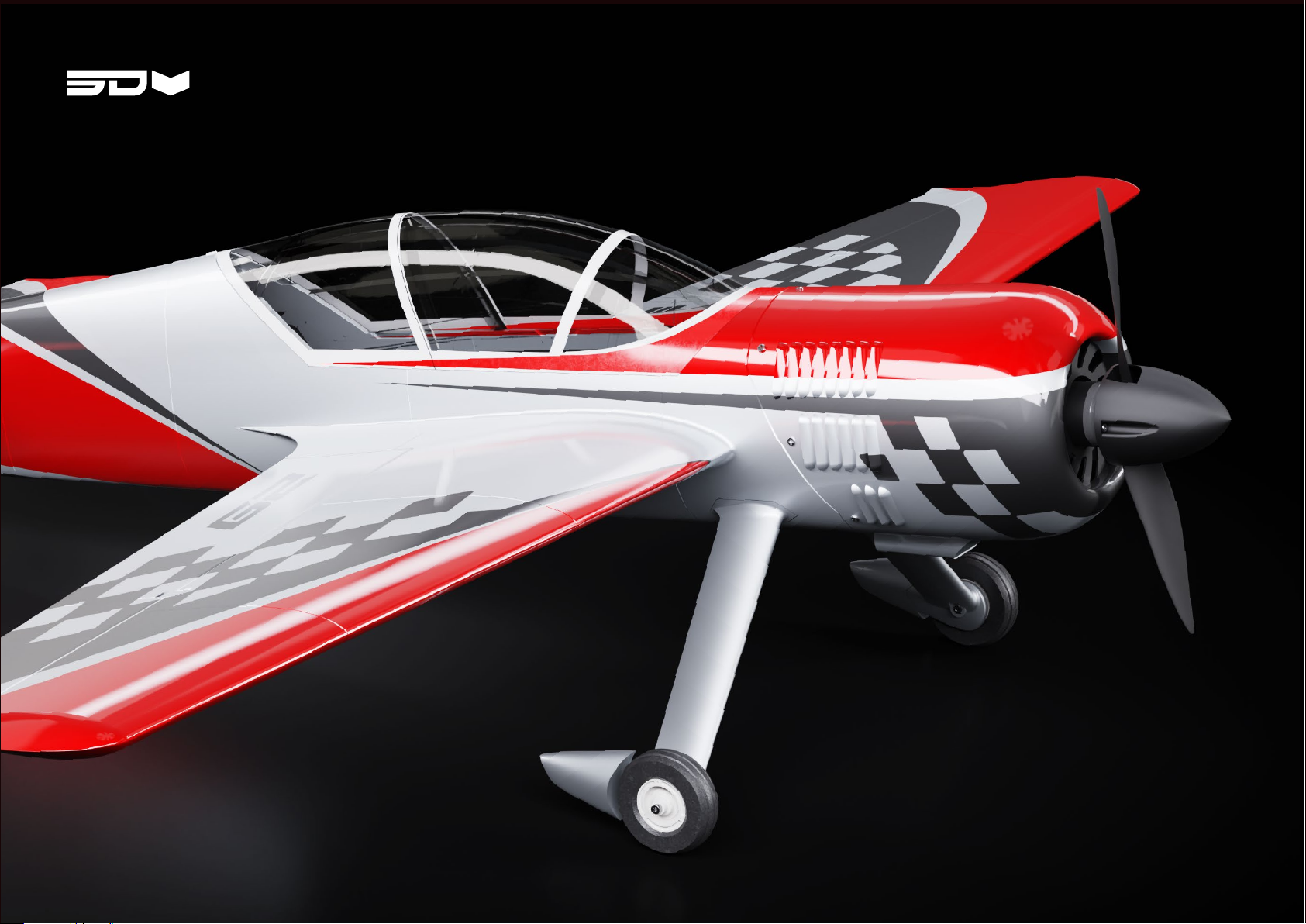
SU-29
Ver. 1.1BUILD GUIDE
Page 2

2
FAIR DATA USE
SAFETY PRECAUTIONS AND WARNINGS
3
Dear Pilots,
we are thrilled to bring you our latest creation and we can’t wait for you to try it out.
However, we must bring to your attention the extensive process and resources that went
into the development of this model. With this in mind, we humbly appeal to your fairness in
protecting the integrity of our data.
friends or online communities. Your cooperation in maintaining the fairness of data use will
enable us to continue bringing you new and innovative models.
Thanks for joining us in our mission to make 3D printed RC planes accessible and thrilling for all.
We appreciate your understanding and support, and your love for aviation.
Best regards,
3DBlackbox
• Always keep a safe distance in all directions around your model
to avoid collisions or injury. This model is controlled by a radio
signal subject to interference from many sources outside your
control. Interference can cause momentary loss of control.
• Always operate your model in open spaces away from full-size
• Always carefully follow the directions and warnings for this
and any optional support equipment (chargers, rechargeable
battery packs, etc.).
• Always keep all chemicals, small parts and anything electrical
out of the reach of children.
•
designed and protected for this purpose. Moisture causes
damage to electronics.
• Never place any portion of the model in your mouth as it could
cause serious injury or even death.
• Never operate your model with low transmitter batteries
• Always keep aircraft in sight and under control.
• Always use fully charged batteries.
• Always keep transmitter powered on while aircraft is powered.
• Always remove batteries before disassembly.
• Always keep moving parts clean.
• Always keep parts dry.
• Always let parts cool after use before touching.
• Always remove batteries after use.
•
• Never operate aircraft with damaged wiring.
• Never touch moving parts.
IMPORTANT
While we strive to develop our models to the best of our knowledge and ability, we disclaim any liability for consequential damages and injuries resulting
from improper use or incorrectly printed parts. Users are advised to handle motors, batteries, and propellers with care. Ensure your model is operated with
appropriate insurance coverage and only in designated, approved areas.
Page 3

4
TABLE OF CONTENTS
5
Introduction Print Files
About the SU-29 06 What’s included 13
Specications
07 Folder Structure 14
Overview
Hardware
10
9
20
25
25
Hardware
Bill of Material
Print Settings
Simplifying 3D printing 27
About Lightweight PLA
Calibration
15
21
Slicers
28
28
29
Build Guide Setup
Fuselage 31 Wing 55 Center of Gravity 61
Elevator
Rudder
Tail
Landing Gear
Tail Wheel
Motor Mount
Cowl
Spinner
40 Aileron 56 Control Directions 62
43 Aileron Servo 57 Rates & Throws 63
44 Wing Mounting 58
45 Final Assembly 59
46
47
48
50
Elevator Servo
Rudder Servo
Battery
Canopy
51
52
53
54
Page 4
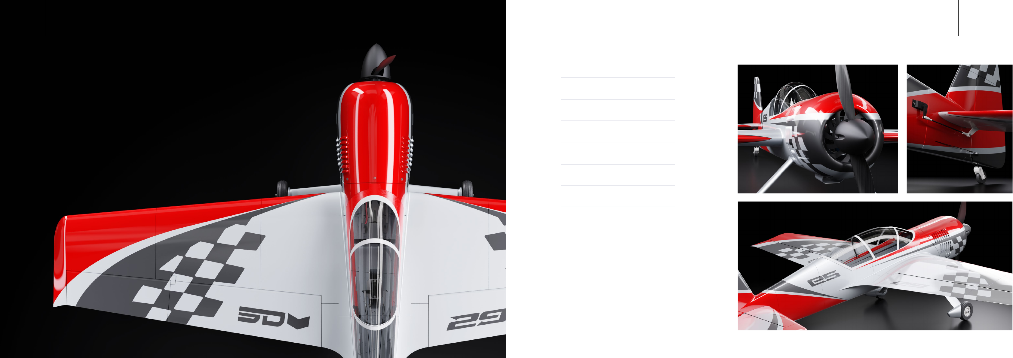
DEFY GRAVITY.
SPECIFICATIONS
76
DOMINATE THE SKY.
Introducing the SU-29 V2, a semi-scale 3D printed aerobatic plane that pays
homage to a timeless classic while integrating modern advancements.
Designed with meticulous attention to detail, the SU-29 V2 excels in performance,
appearance, ease of use, and printability. Its clean vase mode design enables
unmatched printing quality using LW-PLA, resulting in a lightweight yet robust
construction that ensures exceptional 3D performance and reliability for daily use.
The SU-29 V2’s compact form factor not only facilitates a rapid build time
Each servo position and the pull-pull rudder system are engineered for short,
play-free linkages, guaranteeing high precision in the large control surfaces.
Printed Weight
Take-O Weight
Stall Speed
Wing Span
Wing Loading
Wing Area
Length
690 g
1250 g
28 km/h
1160 mm
46g/ dm²
27 dm²
1084 mm
Page 5
HARDWARE
3D Printer Filament
98
HARDWARE
01
Minimum Printer Volume:
210×210×220 (X,Y,Z,)
Nozzle diameter: 0.4 mm
Motor
3S: 2820 1250KV
4S: 2820 880KV
Airframe: LW-PLA
Accessories: PETG, ABS or PC
Tires: TPU A95/ Varioshore
Servos ESC
4 x Savöx SH-0255MG+
Alternatively, use servos of 22.8 x 12.0 x
29.4 mm and 3 kg/cm torque.
Current 55A
Voltage up to 14,8V / 4S
Ensure that the ESC ts your engine.
4 - 5 Channel
requires a Y-cable for the ailerons.
BatteryReceiver
3S: 2400mAh - 2600mAh 30C
4S: 1800mAh - 2200mAh 45C
Propeller
Acro: 2 Blade 12×7 inch
Normal: 2 Blade 12×6 inch
Page 6
HARDWARE BILL OF MATERIAL
HARDWARE BILL OF MATERIAL
1110
Socket Head Cap Screw (SHCS)
PartID Amount
M3 x 30 mm Wheel Axis
56
57
58
M3 x 12 mm
M3 Nuts
Wing Mount
Motor MountM3 x 10 mm
Self tapping Hex Screw
PartID Amount
59
M2× 8 mm Self-Tapping Screw
Cowl
2 x55
4 x
4 x
10 x
5 x
Carbon Tubes / Rods
PartID Amount
Carbon Tube 8 mm x 6 mm x 1000 mm – Wing
Carbon Rod
63
Carbon Rod
64
Carbon Rod
65
Carbon Rod
66
Carbon Rod
67
68 1 x
Carbon Rod
3 mm x 507 mm – Aileron
3 mm x 225 mm – Rudder
3 mm x 450 mm – Elevator
3 mm x 176 mm – Landing Gear
2 mm x 45 mm – Tail Wheel
2 mm x 16 mm – Tail Wheel Axis
1 x62
2 x
1 x
1 x
4 x
2 x
Ballpoint Pen Spring
PartID Amount
Spring 0.4×5×25mm – Canopy Lock
Servo Linkages
PartID Amount
M2 Clevis
Ball Joint Connector
72
M2 Threaded Rod
73
Pull/Pull Steel Wire
74
1 x70
5 x71
3 x
3 x
~ 1200mm
Velcro Strap
PartID Amount
Velcro Strap 300 x 20mm – Battery
Required Tools
Tools
Scalpel
8mm, 10mm
Drill
CA Glue
Screwdriver
Medium
Hex, Phillips
1 x77
60
M2× 6 mm Self-Tapping Screw
61
M2× 4 mm Self-Tapping Screw
Servo Cover
Spinner
8 x
2 x
Stop Collar
PartID Amount
Stop Collar
69
3/8 – Landing Gear
2×
M2 Eyebolt
75
Wire Clamping Sleeve
76
1.6 mm - 1.8 mm
2 x
4×
Page 7
INTRODUCTION
WHAT’S INCLUDED
1312
PRINT FILES
02
We are here to simplify your printing experience and bring your builds to
of the standard .stl format, we use .3MF/.factory, which includes all settings
and part orientation details.
Additionally we have included detailed documents with screenshots of all
slicer settings used. This way, you can easily replicate the settings and be
on your way to creating amazing builds.
•
•
•
•
•
•
Page 8
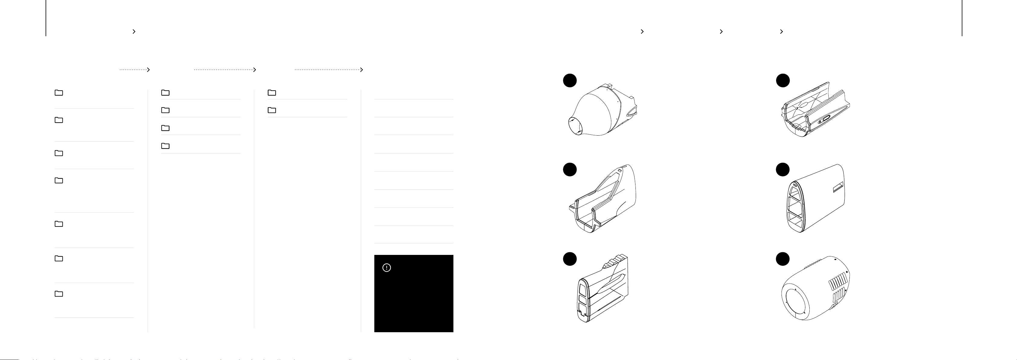
PRINT FILES FOLDER STRUCTURE
Download Folder Material Prole Select le & print
PRINT FILES OVERVIEW
1 2
1514
00_Instructions
Documentation and Settings
01_Bambu Studio
Bambu Studio
02_Prusa_Slicer
03_Cura
(.fdm_material) for Cura
04_Simplify3D
for Simplify3D
05_STL
3D Files (.stl) for the LED covers
for SLA printing (optional)
06_GCodes
for i3 style printers.
LW-PLA Prole_P1
PETG Prole_P2
PLA
TPU
Aileron_L1
Aileron_L2
Aileron_L3
Aileron_R1
Aileron_R2
Aileron_R3
Canopy_C1
Canopy_C2
…
IMPORTANT
For further insight into the
proper print settings, please
refer to the print settings
section beginning on page 23.
information you need to
ensure successful 3D printing.
Fuse-F1
Prole: P1
Material: LW-PLA
Weight: 52.02 g
3
4
Fuse-F3
Prole: P1
Material: LW-PLA
Weight: 32.76 g
5
6
Fuse-F5
Prole: P1
Material: LW-PLA
Weight: 18.40 g
Fuse-F2
Prole: P1
Material: LW-PLA
Weight: 37.68g
Fuse-F4
Prole: P1
Material: LW-PLA
Weight: 27.03g
Cowl-C2
Prole: P1
Material: LW-PLA
Weight: 34.61 g
Page 9
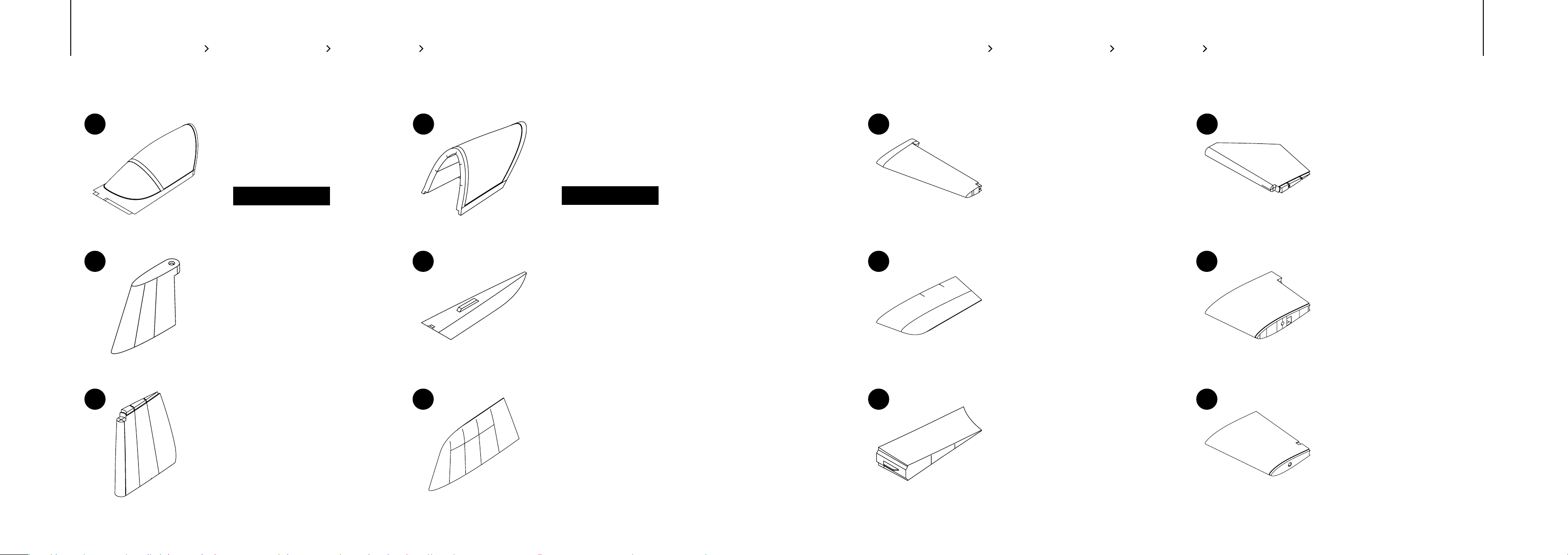
PRINT FILES OVERVIEW
PRINT FILES OVERVIEW
1716
7 8
9
Canopy_C1
Prole: P1
Material: LW-PLA
Weight: 18.04 g
ADDITIONAL SETTINGS
Layer-Height: 0.14mm
Stabilizer
Prole: P1
Material: LW-PLA
Weight: 3.49 g
10
Canopy_C2
Prole: P1
Material: LW-PLA
Weight: 12.69 g
ADDITIONAL SETTINGS
Bottom Layers: 0
Rudder_R1
Prole: P1
Material: LW-PLA
Weight: 1.41 g
13 14
Elevator_L1/R1
Prole: P1
Material: LW-PLA
Weight: 11.46g
15
16
Elevator_L3/R3
Prole: P1
Material: LW-PLA
Weight: 3.97 g
Elevator_L2/R2
Prole: P1
Material: LW-PLA
Weight: 10.49 g
Wing_L1/R1
Prole: P1
Material: LW-PLA
Weight: 31.71 g
11
Rudder_R2
Prole: P1
Material: LW-PLA
Weight: 15.34 g
12
Rudder_R3
Prole: P1
Material: LW-PLA
Weight: 4.93 g
17
Wing_L2/R2
Prole: P1
Material: LW-PLA
Weight: 2.42 g
18
Wing_L3/R3
Prole: P1
Material: LW-PLA
Weight: 30.05 g
Page 10
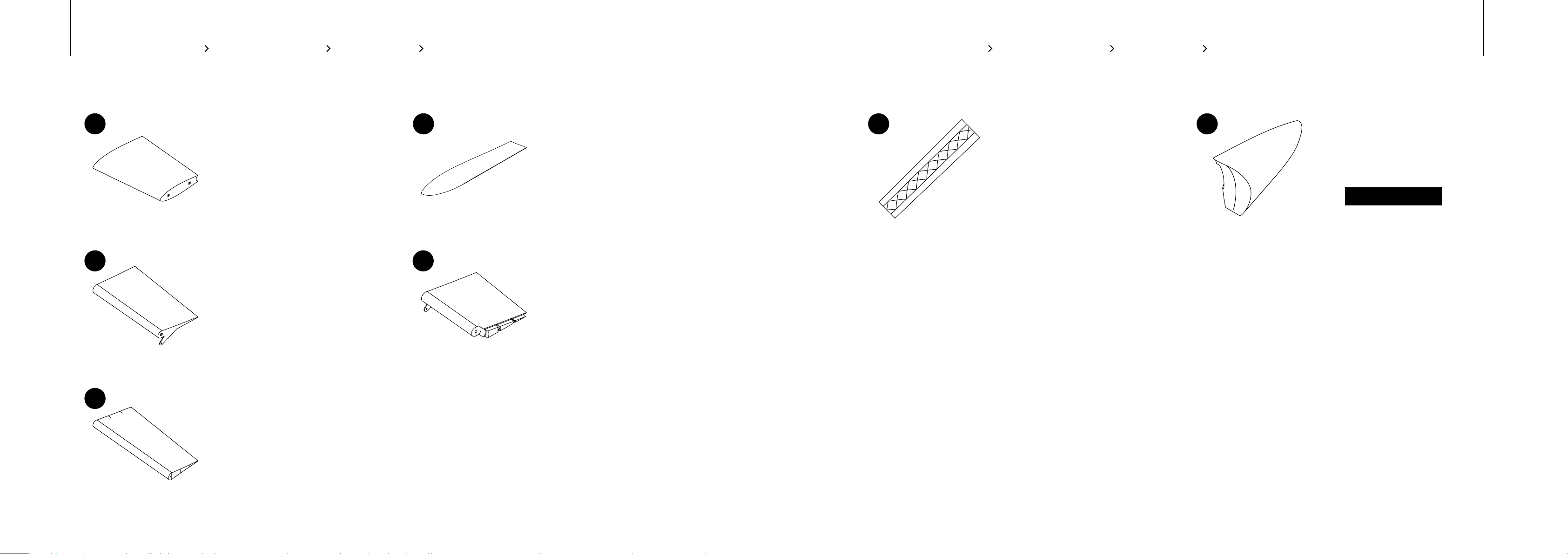
PRINT FILES OVERVIEW
PRINT FILES OVERVIEW
1918
19 20
Wing_L4/R4
Prole: P1
Material: LW-PLA
Weight: 18.80 g
21 22
Aileron-L1/R1
Prole: P1
Material: LW-PLA
Weight: 10.69 g
Wing_L5/R5
Prole: P1
Material: LW-PLA
Weight: 3.78 g
Aileron-L2/R2
Prole: P1
Material: LW-PLA
Weight: 6.25 g
24 25
Landing_Gear_L1/R1
Prole: P1
Material: LW-PLA
Weight: 5.19 g
Wheel_Pants_L/R
Prole: P1
Material: LW-PLA
Weight: 2.03 g
ADDITIONAL SETTINGS
Layer Height: 0.14
23
Aileron-L3/R3
Prole: P1
Material: LW-PLA
Weight: 9.07 g
Page 11
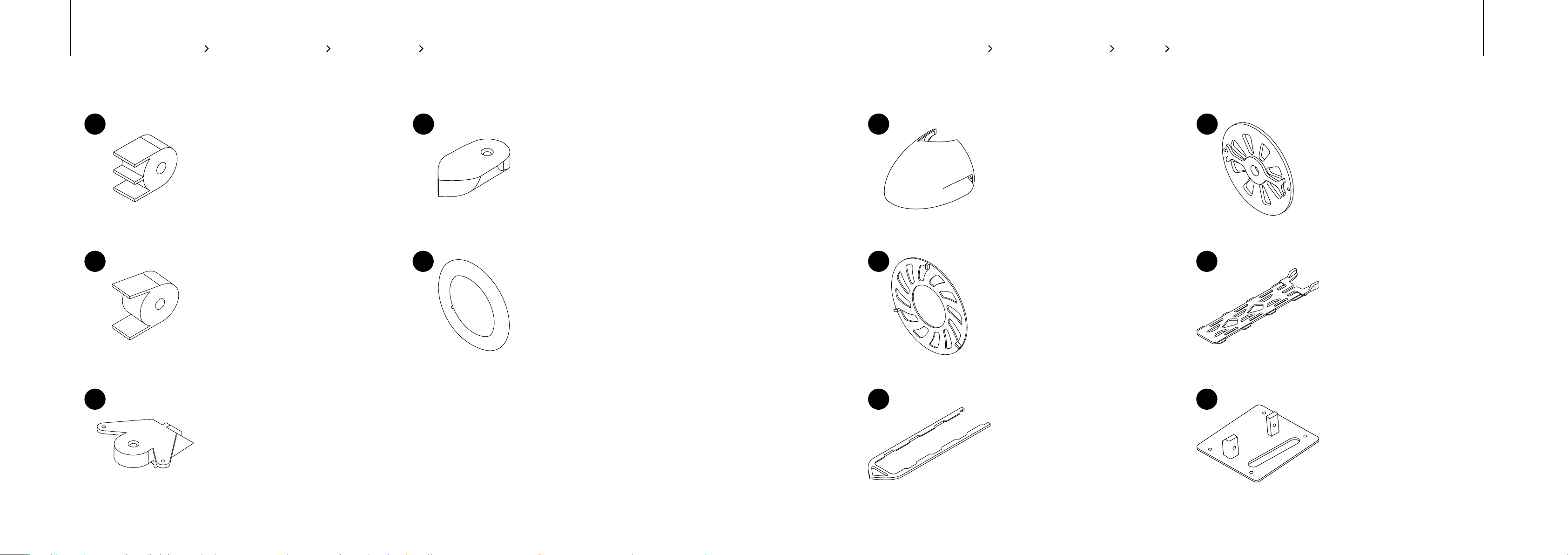
PRINT FILES OVERVIEW PRINT FILES OVERVIEW PLA
2120
26 27
Elevator_Hinge_L/R
Prole: P2
Material: LW-PLA
Weight: 0.71 g
28
29
Wing_Hinge_L/R
Prole: P2
Material: LW-PLA
Weight: 0.76 g
Rudder_Hinge
Prole: P2
Material: LW-PLA
Weight: 1.24 g
Cowl_C1
Prole: P2
Material: LW-PLA
Weight: 9.31 g
31 32
Spinner
Prole: P2
Material: PLA
Weight: 7.58 g
33
34
Cowl_C3
Prole: P2
Material: PLA
Weight: 5.06 g
Spinner_Base
Prole: P2
Material: PLA
Weight: 4.03 g
Battery_Mount
Prole: P2
Material: PLA
Weight: 9.48 g
30
Rudder_Servohorn
Prole: P2
Material: LW-PLA
Weight: 3.18 g
35
Battery_Mount_Rail
Prole: P2
Material: PLA
Weight: 5.48 g
36
Servo_Cover_L/R
Prole: P2
Material: PLA
Weight: 4.18 g
Page 12
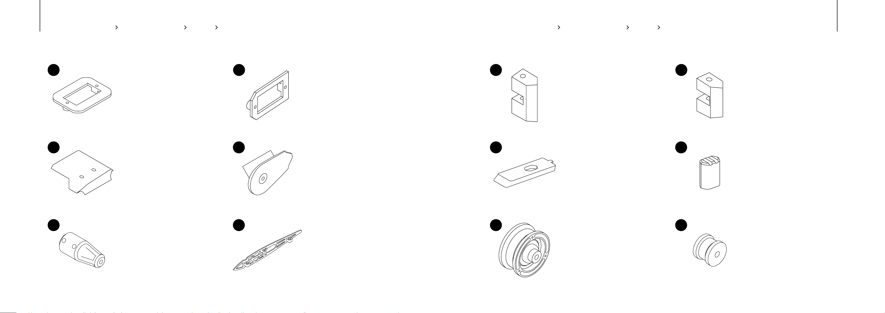
PRINT FILES OVERVIEW PLA
PRINT FILES OVERVIEW PLA
2322
37 38
Rudder_Servo_Mount
Prole: P2
Material: PLA
Weight: 1.60 g
39
40
Landing_Gear_Mount_L/R
Prole: P2
Material: PLA
Weight: 9.01 g
Elevator_Servo_Mount
Prole: P2
Material: PLA
Weight: 1.08 g
Landing_Gear_L2/R2
Prole: P2
Material: PLA
Weight: 5.02 g
43 44
Wing_Mount_L1/R1
Prole: P2
Material: PLA
Weight: 2.55 g
45
46
Canopy_Lock
Prole: P2
Material: PLA
Weight: 1.18 g
Wing_Mount_L2/R2
Prole: P2
Material: PLA
Weight: 1.77 g
Canopy_Lock_Grip
Prole: P2
Material: PLA
Weight: 0.58 g
41
Tail_Wheel_Mount
Prole: P2
Material: PLA
Weight: 1.89 g
42
Wing_Mount_L/R
Prole: P2
Material: PLA
Weight: 5.95 g
47
Wheel_L/R
Prole: P2
Material: PLA
Weight: 4.19 g
48
Tail_Wheel
Prole: P2
Material: PLA
Weight: 0.69 g
Page 13
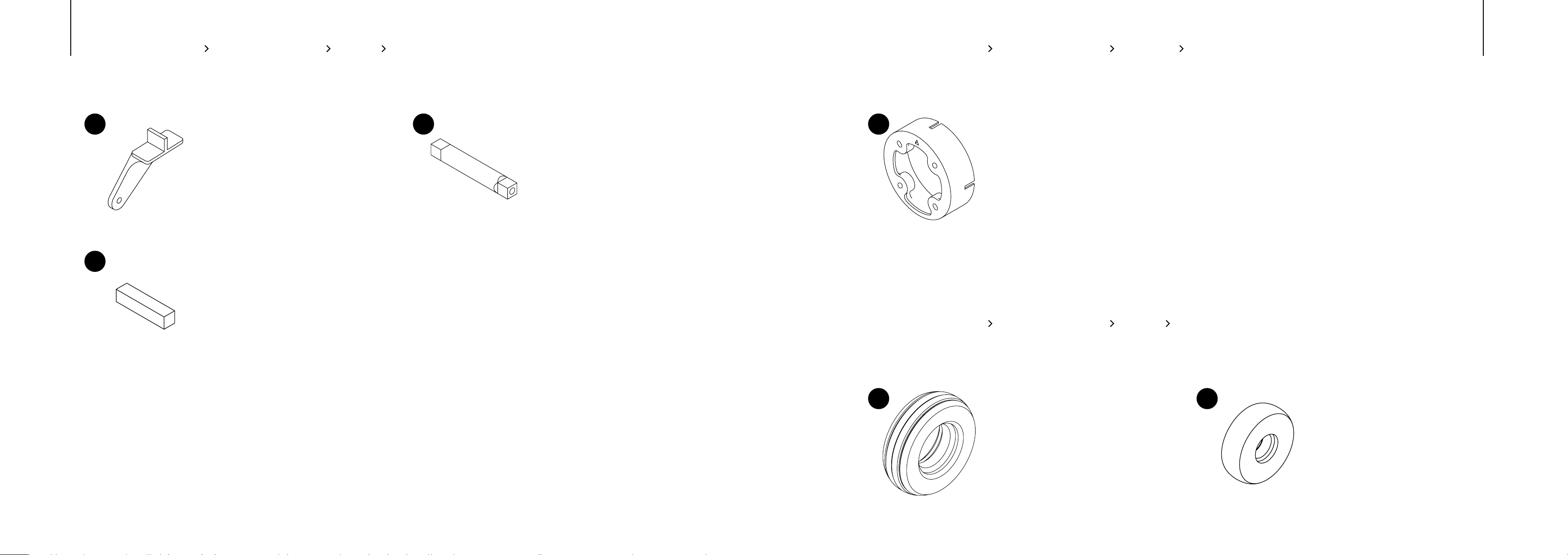
PRINT FILES OVERVIEW PLA
PRINT FILES OVERVIEW PETG
2524
49 50
Elevator_Servohorn
Prole: P2
Material: PLA
Weight: 1.01 g
51
Alignment_Tab
Prole: P2
Material: PLA
Weight: 0.34 g
Elevator_Joint
Prole: P2
Material: PLA
Weight: 2.34 g
52
Motor_Mount
Prole: P2
Material: PETG or other high temperature resistant Material
Weight: 6.68 g
PRINT FILES OVERVIEW TPU
53 54
Tire_L/R
Prole: P2
Material: TPU Varioshore
Weight: 6.97 g
Tail_Tire
Prole: P2
Material: TPU Varioshore
Weight: 1.39 g
Page 14
PRINT SETTINGS
03
INTRODUCTION
Thin wall printing is a challenging aspect of 3D printing that requires precision and a well-calibrated printer.
In order to produce high-quality prints, it’s essential to have a printer that is properly set up and dialed in.
We understand that the 3D printing community encompasses a diverse range of users, each possessing
unique levels of experience and expertise. The SU-29 has been created with the aim of maximizing user
2726
SIMPLIFYING YOUR PRINT EXPERIENCE
The goal is to make 3D printing more accessible for everyone,
regardless of the skill level, so you can eortlessly enjoy the
advantages of this remarkable technology.
Although we strive to provide standardized settings for all 3D printers, it is important to note that every
machine is unique and may require adjustments to achieve optimal results. We encourage you to
Page 15
PRINT SETTINGS
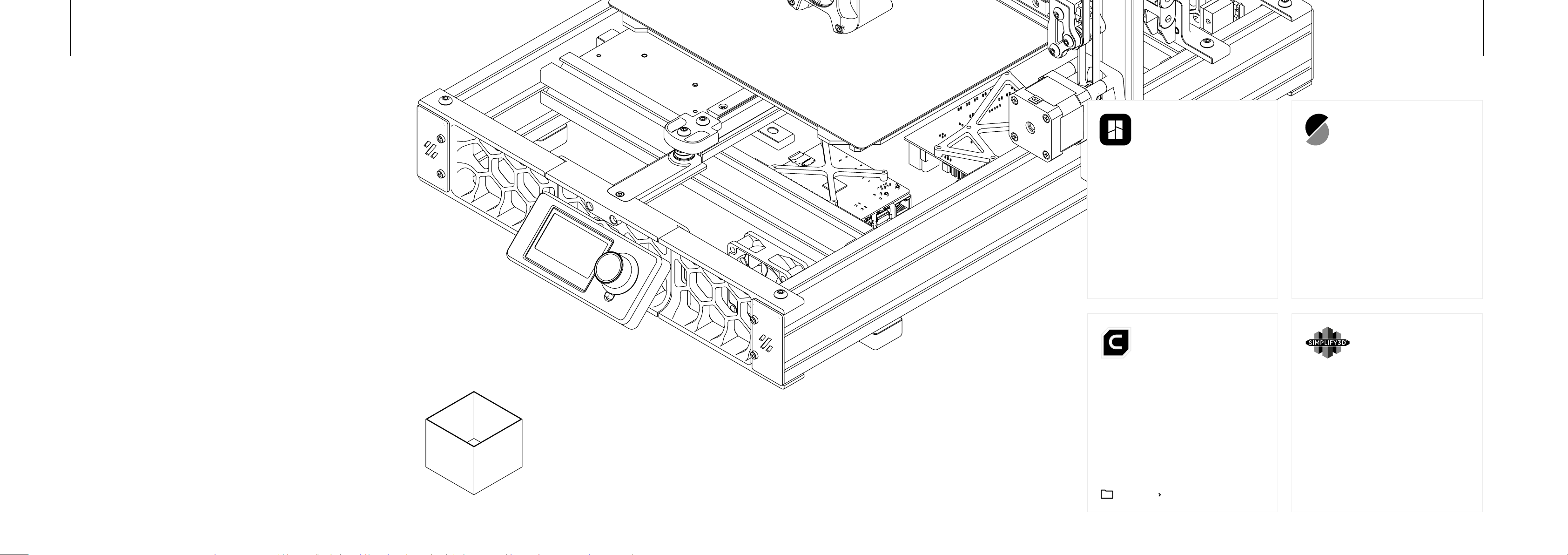
ABOUT LIGHTWEIGHT PLA
It is particularly useful for creating lightweight airplanes due to its unique
product. These properties make it the perfect material for printing our planes.
with layer adhesion, try reducing the cooling fan. Using a heated bed is highly
BAMBU STUDIO
an easy printing experience. However, it’s
recommended to disable automatic ow
calibration and spaghetti detection.
2928
PRUSA SLICER
and select “Open as Project”. This will generate
for you to use as a starting point.
CALIBRATION
The degree of foaming varies depending on parameters such as extrusion
multiplier and temperature. Since every 3D printer is unique, it’s essential to adjust
the print temperature until the wall thickness reaches 0.58 mm (±0.02 mm).
Calibration_Cube
Prole: P1
Material: LW-PLA
Weight: 2.23 g
CURA SLICER
orientation to avoid compatibility issues.
Create a new generic printer matching your
03_Cura Slicer_Settings.pdf
SIMPLIFY3D
print settings for compatibility with your printer.
Simply adjust the build volume in the Gcode
well as modify the start and end routines in the
Scripts tab according to your needs.
Page 16
BUILD GUIDE
04
FUSELAGE
FUSELAGE
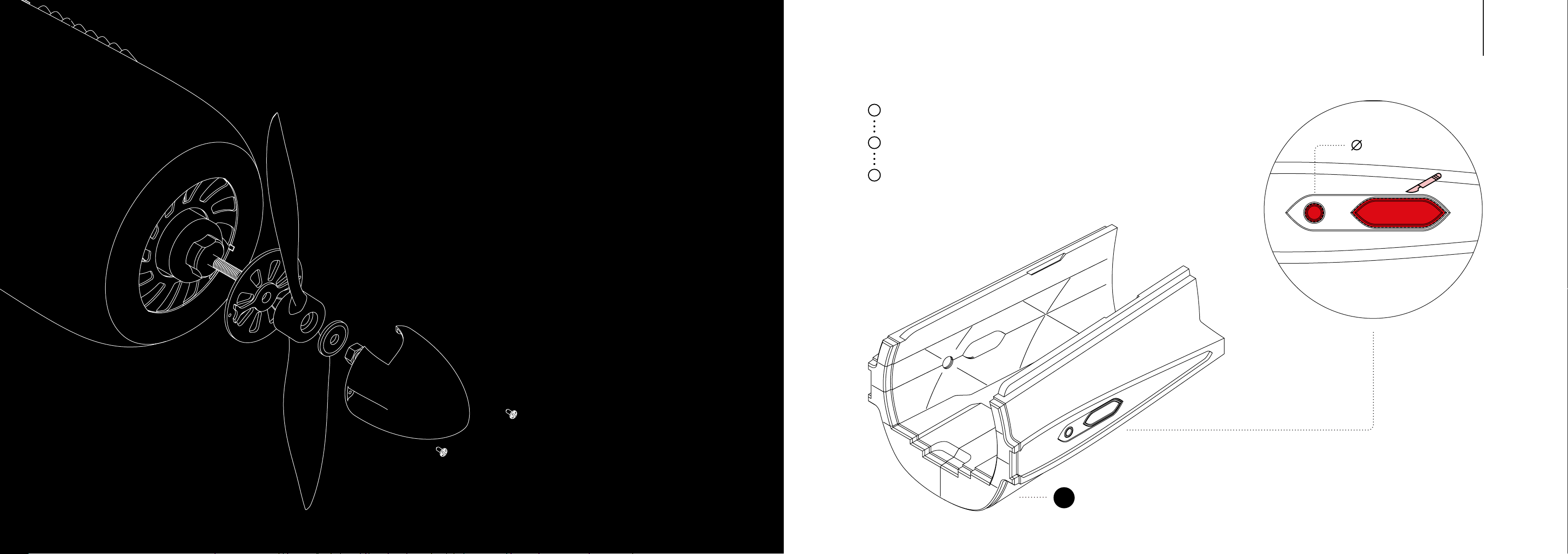
Clean up the edges of all parts,
1
both on the inside and outside.
Drill a hole into the fuselage using
2
a 8 mm drill bit.
Cut out the servo pocket with
3
a sharp knife.
3130
8 mm
2
Page 17
FUSELAGE
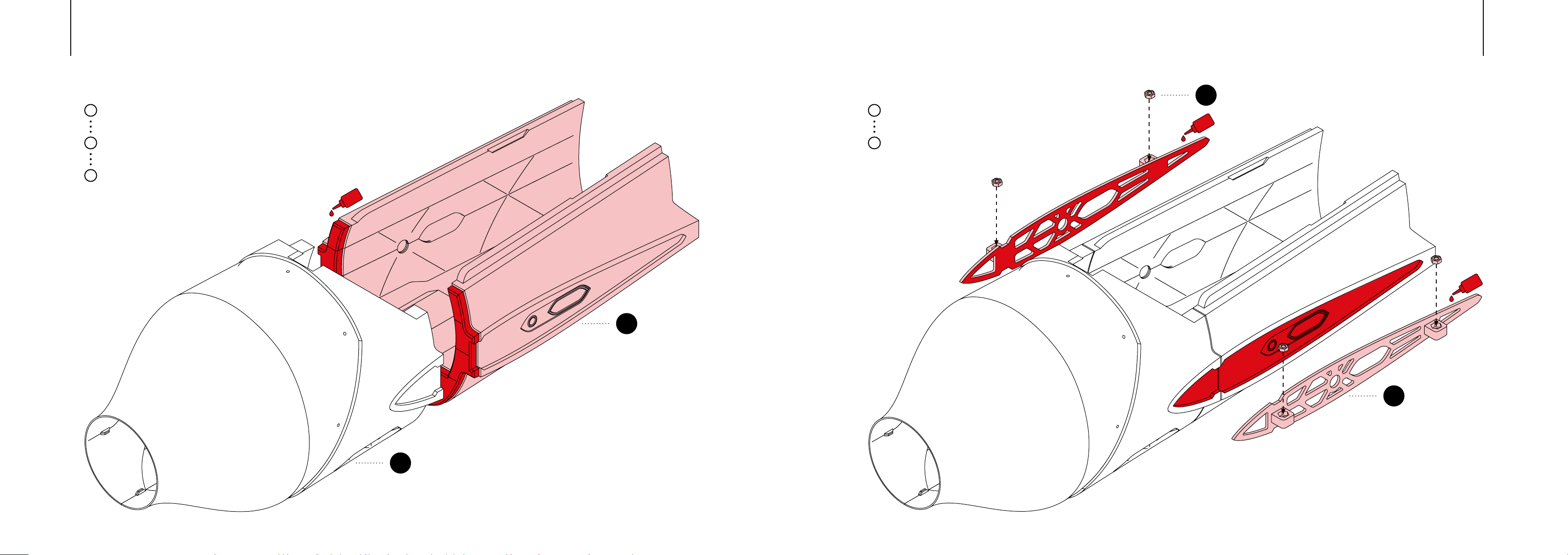
1
Apply medium liquid CA glue to the areas
2
where the parts will attach to each other.
Firmly press the parts together and hold
3
them in place until the glue dries.
CA
FUSELAGE
Apply medium liquid CA glue to the marked
1
Place the M3 nuts into the pockets of the
2
wing mount, and secure them with a drop
of CA glue.
3332
58
CA
CA
2
42
1
Page 18
FUSELAGEFUSELAGE
3534
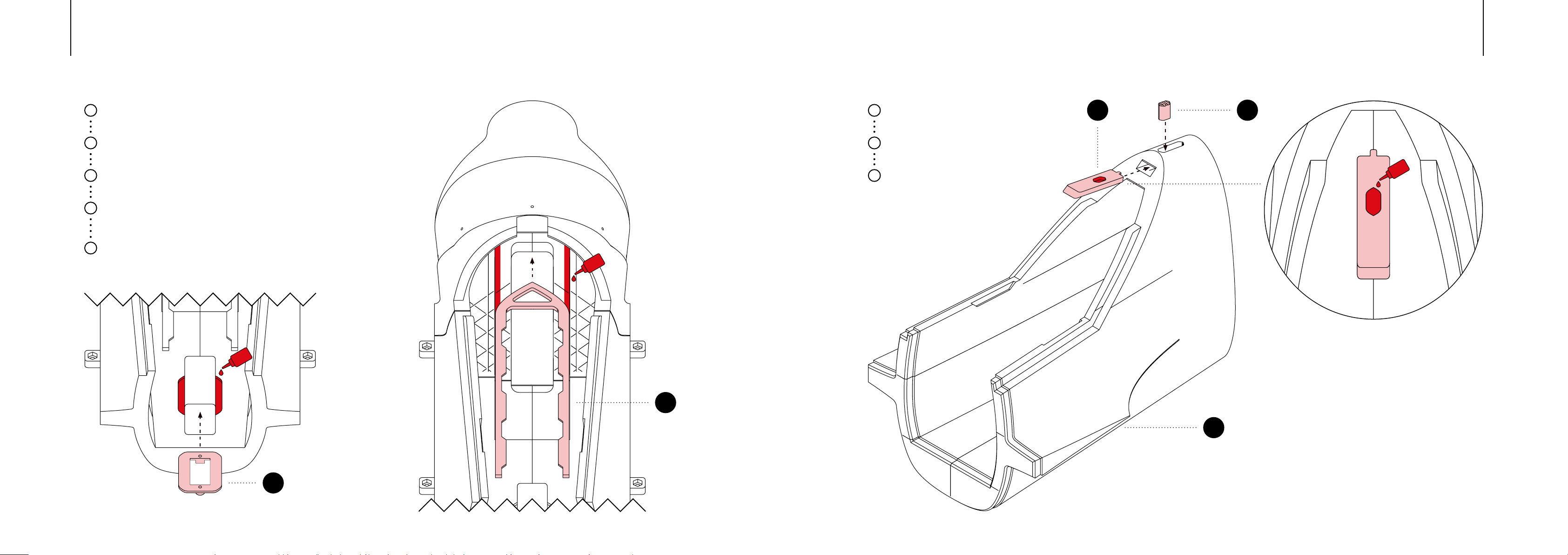
Apply medium liquid CA glue to the
1
marked area.
2
Secure the rudder servo mount in place.
Apply glue to the underside of the
3
battery mount rail.
Attach the rail, ensuring that only direct
4
contact areas are glued to allow the
battery mount to move freely.
5
Allow the glue to dry completely.
CA
CA
Apply glue to the pocket of the
1
canopy lock.
Slide the canopy lock into the third part
2
of the fuselage.
Insert the canopy lock grip from the top,
3
through the hole in the fuselage, and into
the canopy lock.
4645
CA
37
35
3
Page 19
FUSELAGEFUSELAGE
3736
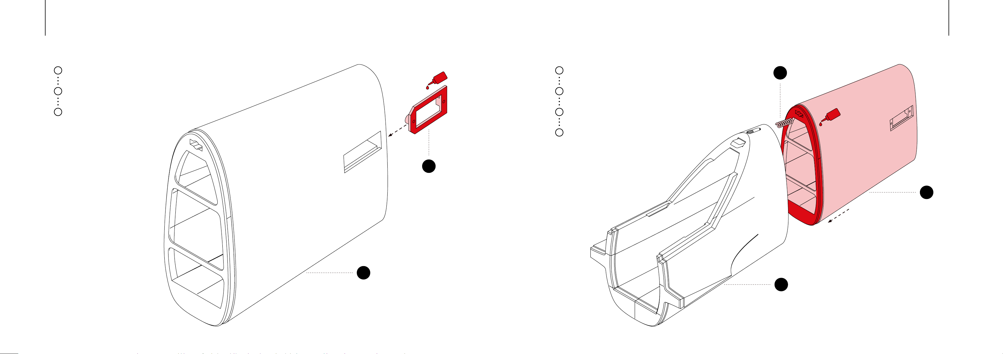
Apply glue to the elevator servo mount.
1
Carefully slide the mount into the fuselage
2
part from the back.
Ensure the mount is properly aligned and
3
allow the glue to dry.
38
CA
Apply medium liquid CA glue to the areas
1
where the parts will attach to each other.
Insert a ballpoint pen spring into the
2
canopy lock channel.
Ensure the notch of the canopy lock is
3
positioned inside the spring.
Firmly press the parts together and hold
4
them in place until the glue dries.
70
CA
4
4
3
Page 20
FUSELAGEFUSELAGE
3938
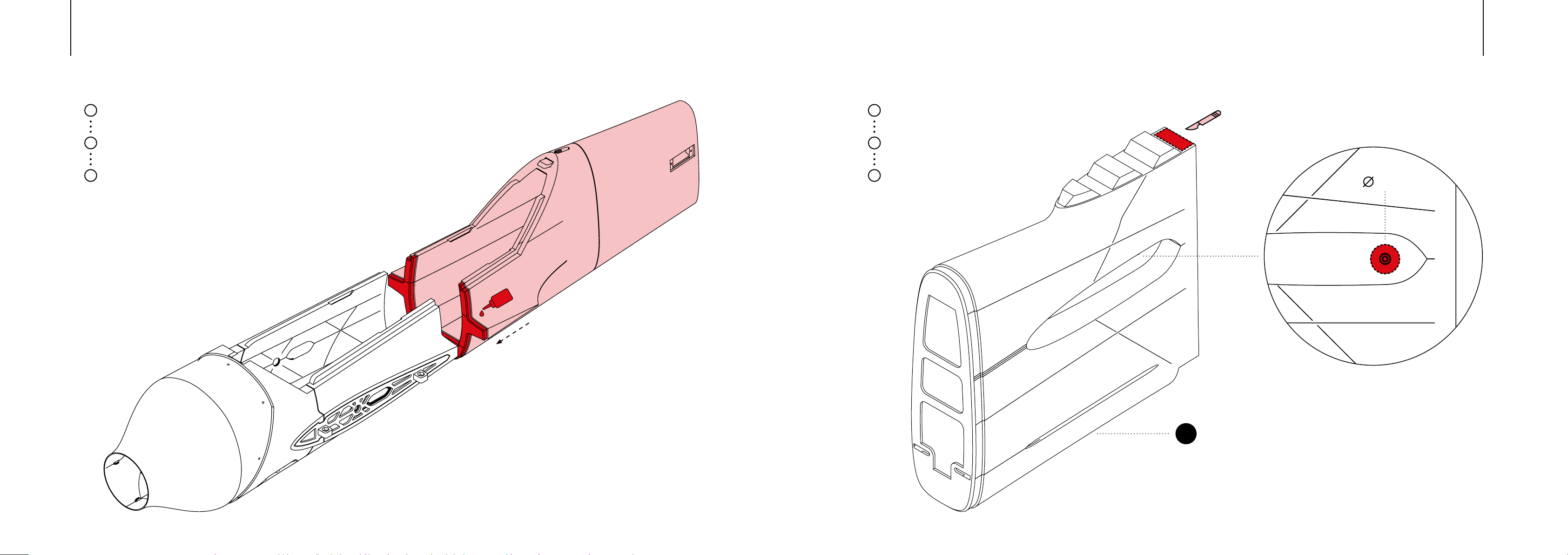
1
Apply medium liquid CA glue to the areas
2
where the parts will attach to each other.
Firmly press the parts together and hold
3
them in place until the glue dries.
CA
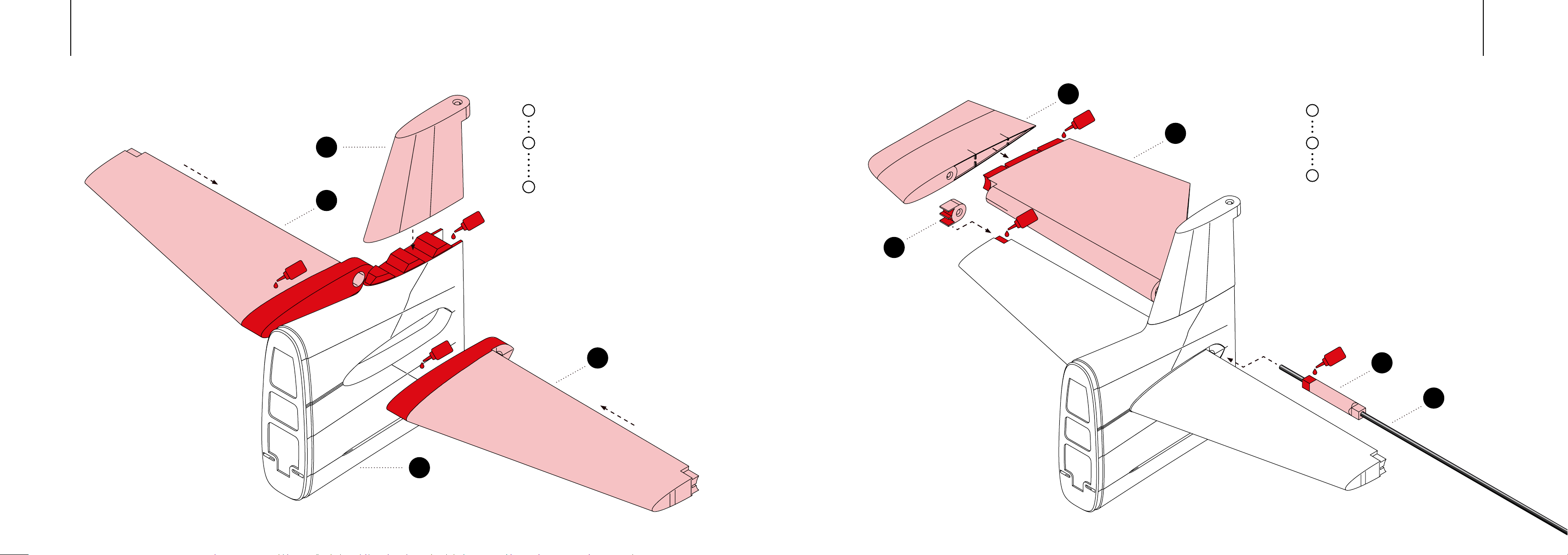
Use a sharp scalpel to cut out the marked
1
area where the rudder will sit.
Drill a 10mm hole into the marked area to
2
accommodate the elevator connector.
Clean any rough edges to ensure a
3
10 mm
5
Page 21
ELEVATOR
13
ELEVATOR
15
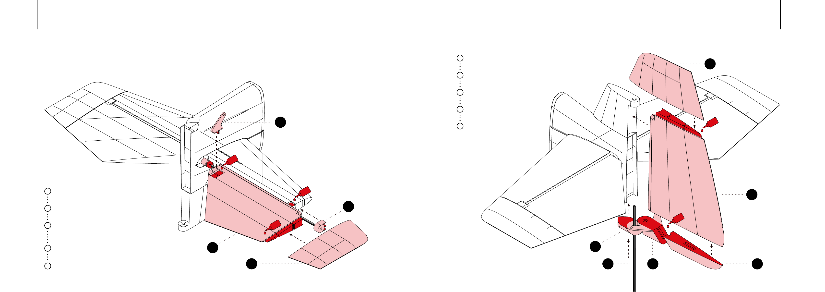
Apply medium liquid CA glue to the areas
1
where the parts will attach to each other.
Ensure no glue is applied around the
9
2
elevator holes to allow the elevator
connector to move freely.
Glue all parts in place, ensuring they are
3
perfectly aligned and square to each other.
CA
14
Apply medium liquid CA glue to the areas
1
where the parts will attach to each other.
Use the carbon rod as guide and slide it
2
through the parts.
Ensure to glue the parts together in the
3
following order: 50 to 14, then 26, and
4140
CA
CA
26
CA
5
13
CA
CA
50
65
Page 22
ELEVATOR
RUDDER
Apply medium liquid CA glue to the areas
1
where the parts will attach to each other.
Glue the rudder mount in place and
2
check the alignment.
Glue the rudder parts together,
3
using the carbon rod as a guide.
Ensure the rudder moves freely.
4
4342
12
Apply medium liquid CA glue to the areas
1
where the parts will attach to each other.
2
Use the carbon rod as guide.
Ensure to glue the parts together in the
3
following order: 50 to 14, then 26, and
Make sure, that both elevator sides are
4
perfectly aligned to each other.
Lastly place the servo horn in position.
5
14
CA
15
CA
49
CA
26
After positioning the rudder, secure
5
the carbon rod with a drop of glue at
the bottom of the rudder mount.
CA
11
CA
27
103064
Page 23
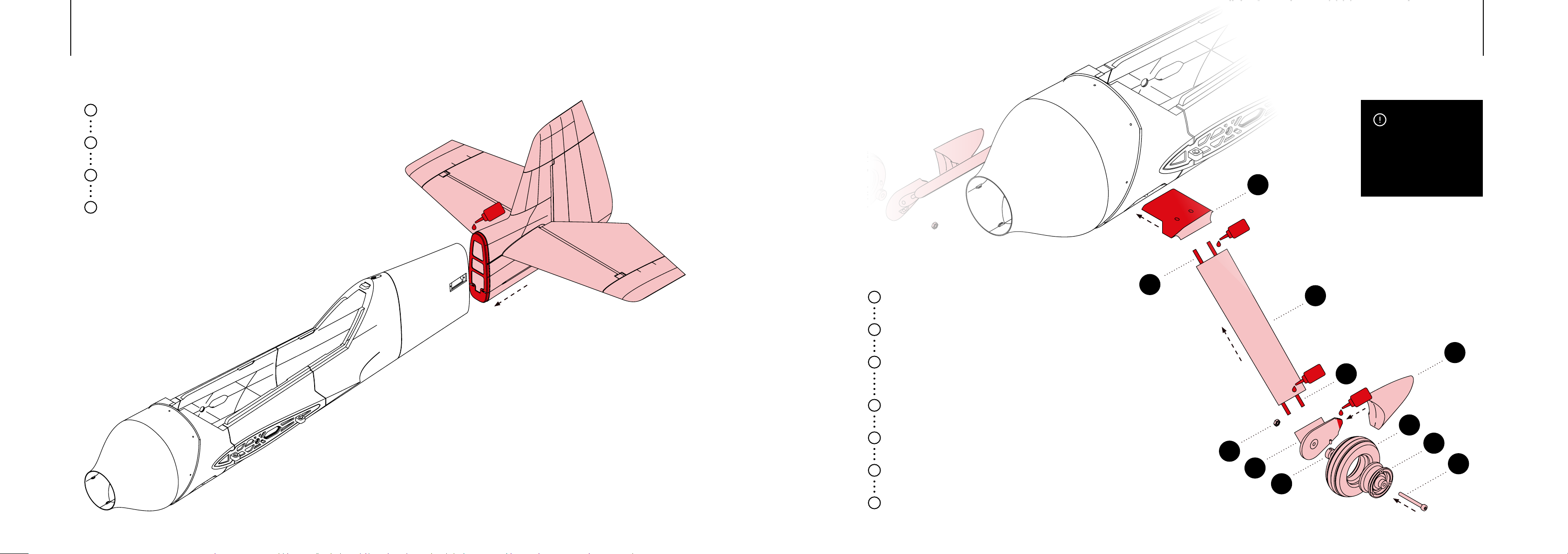
1
LANDING GEARTAIL
4544
IMPORTANT
Make sure the rudder linkage openings
2
are clear and clean.
Apply medium liquid CA glue to the areas
3
where the parts will attach to each other.
Firmly press the parts together and hold
4
them in place until the glue dries.
CA
1
Fit the tire over the wheel.
Glue the wheel pants onto the
2
landing gear.
Insert an M3 Nut into the pocket of the
3
landing gear and secure it with a drop of
glue.
Insert the M3 Screw into the wheel and
4
secure the wheel with a stop collar.
5
Screw the wheel into the landing gear.
Slide the carbon rods into the
6
landing gear.
Apply glue to the landing gear mount and
7
attach it to the fuselage.
66
58
CA
40
39
69
24
CA
Only glue the ends of the
carbon spars, avoiding the
intersecting surfaces. This
movement of the landing gear.
25
66
CA
53
47
55
Page 24
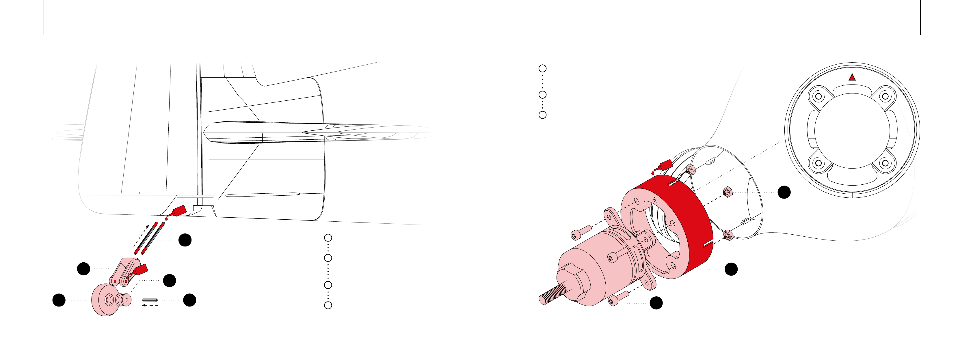
MOTOR MOUNTTAIL WHEEL
Place the M3 nuts in the pockets of the
1
motor mount and secure them with a
drop of glue.
Attach the motor to the motor mount
2
using M3 screws.
Apply glue to the marked area of the motor
3
mount and attach it to the fuselage.
4746
Please ensure
that the arrow is
pointing upwards.
CA
58
54
41
CA
48
CA
67
68
1
Fit the tire over the wheel.
Position the wheel in the tail wheel mount
2
and slide the carbon rod through
the wheel.
Secure the wheel in place with a drop
3
of glue on each side.
Apply glue to the ends of the carbon
4
rods and attach the tail wheel to
the fuselage.
52
57
Page 25
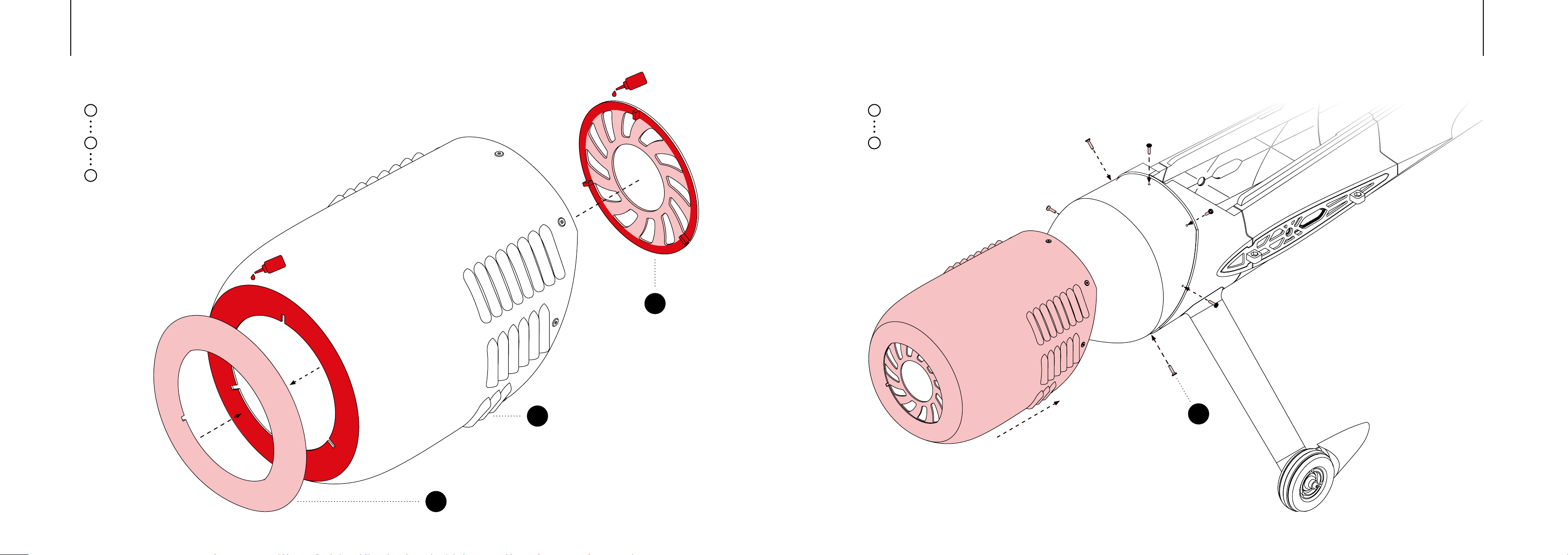
CA
COWLCOWL
4948
1
Apply medium liquid CA glue to the areas
2
where the parts will attach to each other.
Firmly press the parts together and hold
3
them in place until the glue dries.
CA
33
1
fuselage, ensuring it sits properly in place.
Use self-tapping screws to secure the
2
cowl to the fuselage, tightening each
29
6
59
Page 26
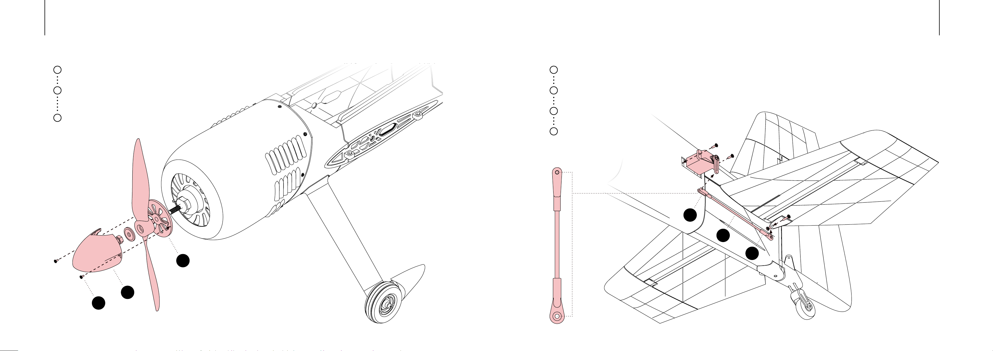
ELEVATOR SERVOSPINNER
5150
Position the spinner mount onto the motor
1
shaft, ensuring it is properly aligned.
Attach the propeller to the motor shaft
2
using the screw provided with the motor,
tightening it securely.
Secure the spinner to the spinner mount
3
using self-tapping screws.
Use a servo tester, to center the servo arm.
1
Fasten the servo in place with the
2
provided screws.
Connect the linkage to the outer
3
hole of the servo arm.
Ensure the control surface aligns
4
perfectly with the elevator.
122 mm
71
73
61
72
32
31
Page 27
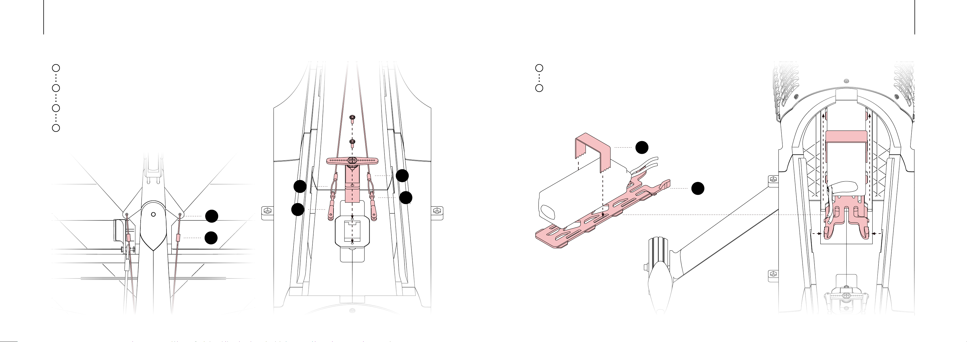
1
Use a servo tester, to center the servo arm.
BATTERYRUDDER SERVO
Strap the battery to the quick-lock
1
battery mount.
5352
Fasten the servo in place with the
2
provided screws.
Cross the ropes of the pull-pull rudder
3
linkage.
Make sure that the ropes are taut and
4
attach the clevis to the outer holes of the
servo arm.
76
74
Place the mount in the rail, press the
2
handles, and slide it into place.
77
76
74
75
71
34
Page 28
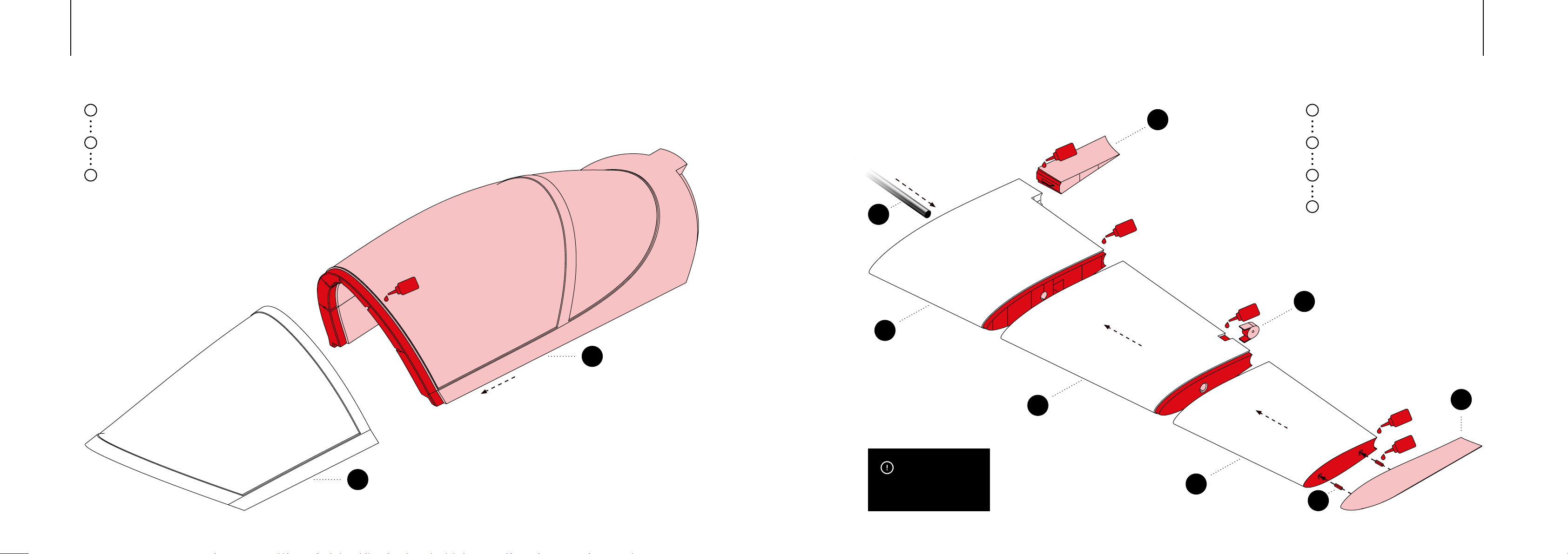
WINGCANOPY
5554
1
Apply medium liquid CA glue to the areas
2
where the parts will attach to each other.
Firmly press the parts together and hold
3
them in place until the glue dries.
CA
1
17
CA
62
CA
28
CA
16
7
Apply medium liquid CA glue to the areas
2
where the parts will attach to each other.
Use the main carbon spar to guide proper
3
alignment of the parts.
Firmly press the parts together and hold
4
them in place until the glue dries.
18
CA
CA
20
IMPORTANT
8
Avoid applying glue on the spar
or the areas surrounding it.
19
51
Page 29
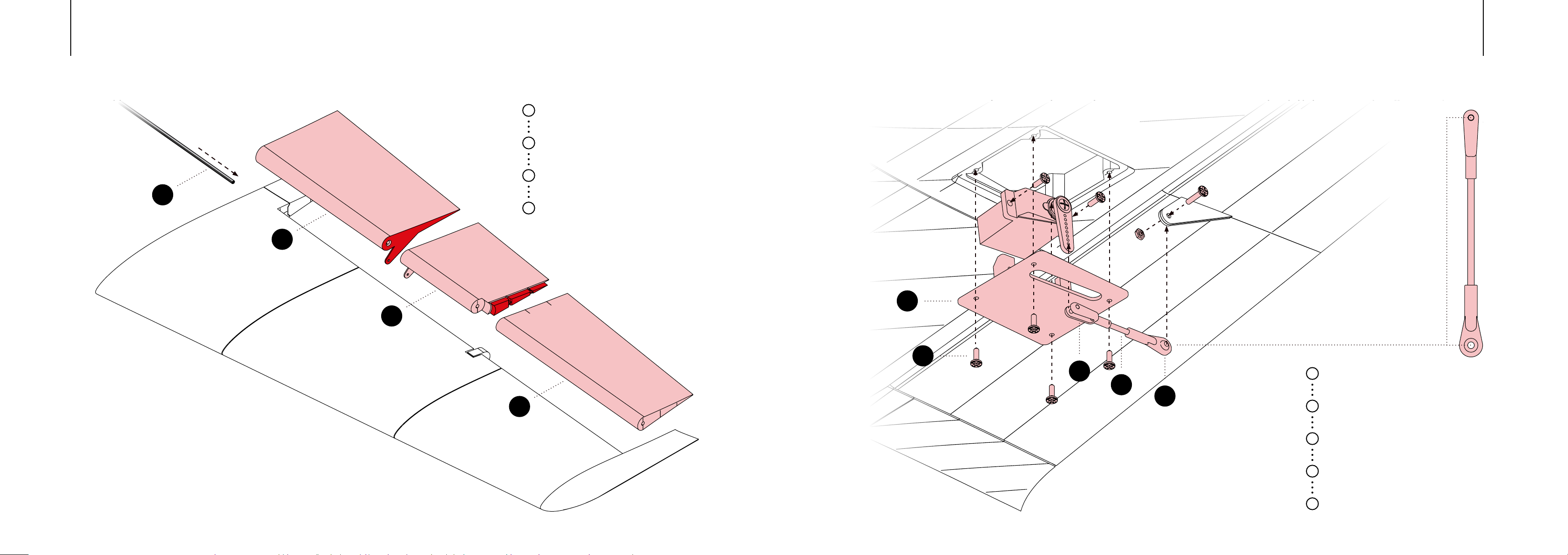
63
AILERON SERVOAILERON
1
Apply medium liquid CA glue to the areas
2
where the parts will attach to each other.
Firmly press the parts together and hold
3
them in place until the glue dries.
Mount the aileron to the wing and secure
4
the carbon rod with a drop of glue at
the root.
21
36
22
46 mm
5756
23
60
71
73
72
1
Use a servo tester, to center the servo arm.
Fasten the servo in place with the
2
provided screws.
Attach the servo mount to the wing using
3
M2 self-tapping screws.
Connect the linkage to the outer
4
hole of the servo arm.
Ensure the control surface aligns
5
perfectly with the elevator.
Page 30
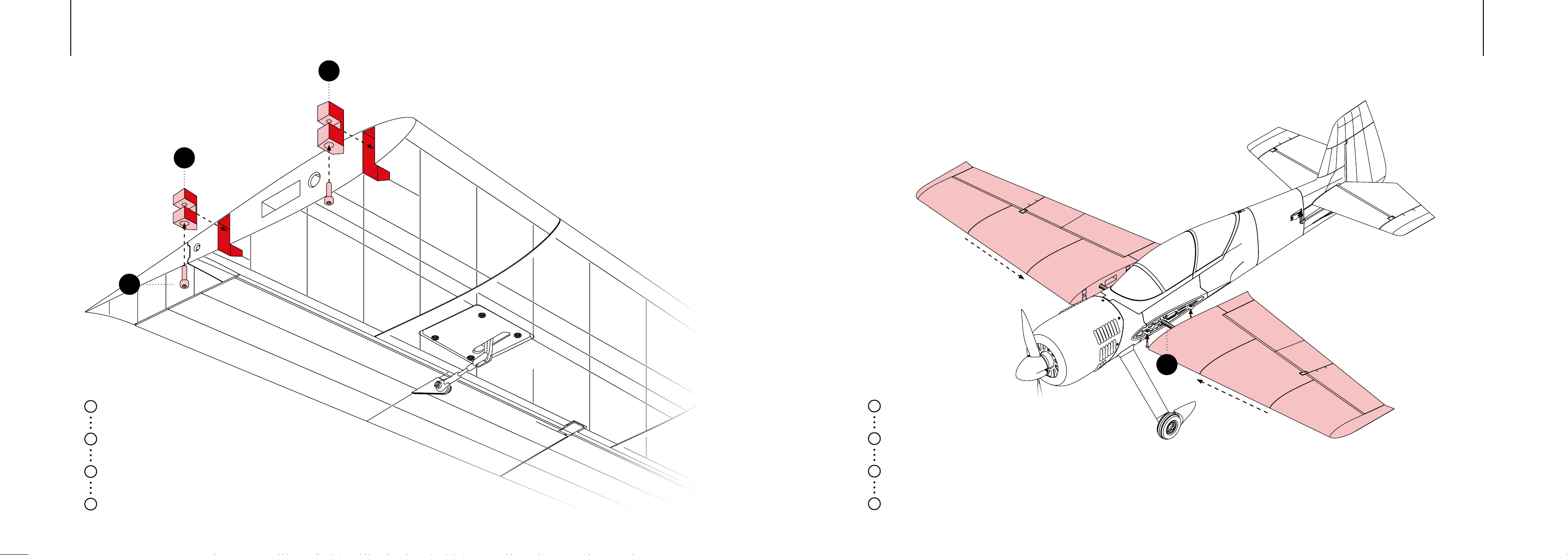
56
44
43
FINAL ASSEMBLYWING MOUNTING
5958
1
Apply medium liquid CA glue to the areas
2
where the parts will attach to each other.
Firmly press the parts together and hold
3
them in place until the glue dries.
Use M3 screws when attatching the wings
4
to the fuselage.
Insert the main carbon spar into
1
the fuselage.
2
Slide the wings onto the main carbon spar
Secure the wings to the fuselage with
3
M3 screws.
Connect all electronic components
4
to the receiver.
62
Page 31
SETUP
04
CENTER OF GRAVITY
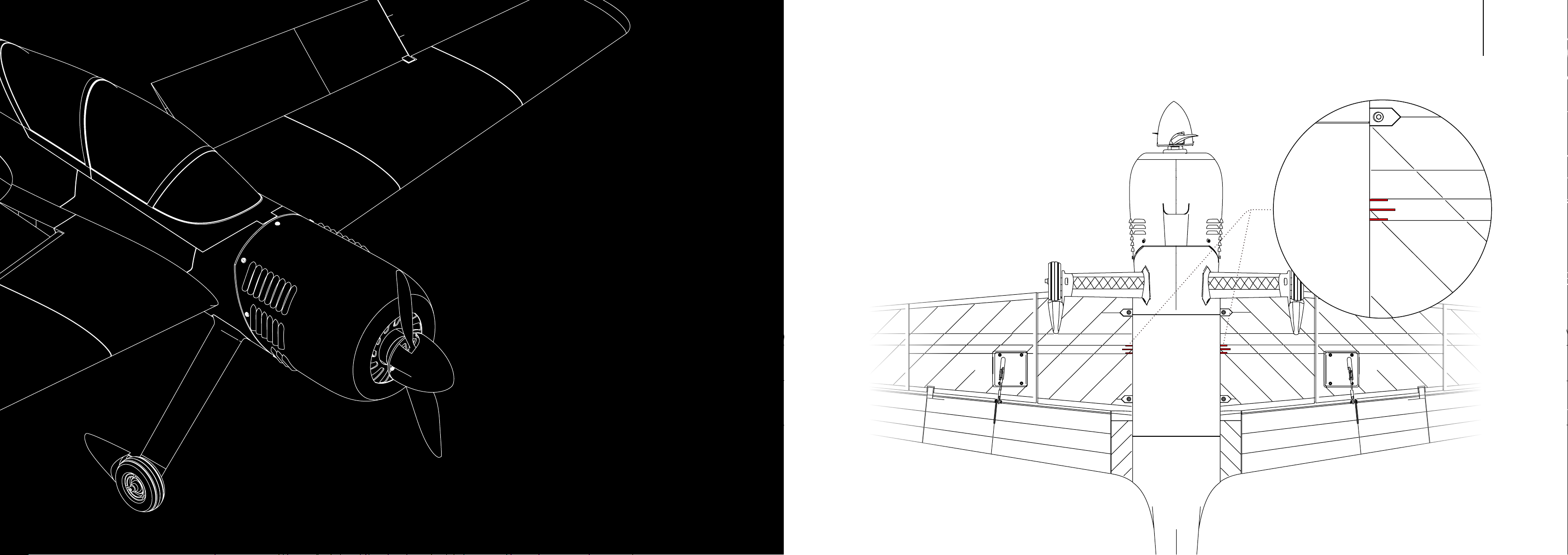
The Center of Gravity (CoG) is marked on the
style, we suggest using the most forward marking
and last markings. The rearmost position is
recommended only for experienced pilots
who prefer a neutral CoG.
6160
CoG
Page 32
CONTROL DIRECTIONS
RATES & THROWS
6362
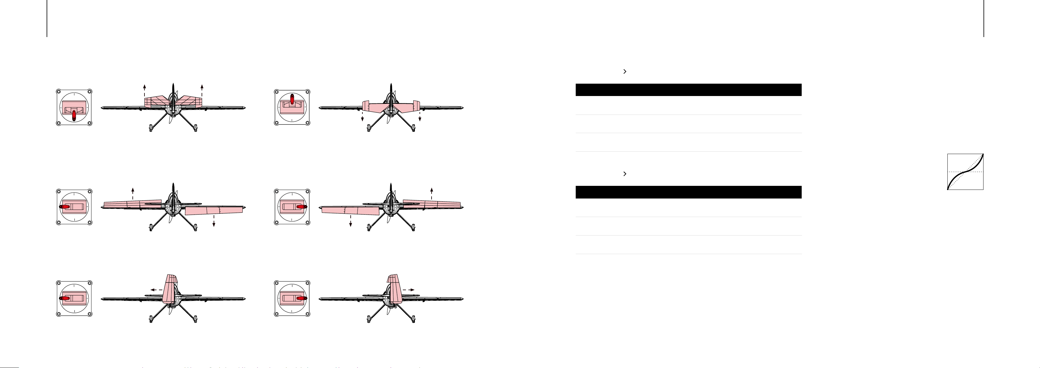
Pitch
Roll
Rudder
Servo Travel
Stick input
Pitch
Roll
Rudder
Servo Travel
Stick input
Pitch
Roll
Rudder
These basic settings are only a recommendation and can be changed according to your
own preferences.
Dual Rate – Low
Dierential
0%
15%
0%
Dual Rate – High
Dierential
0%
15%
0%
Expo
40%
40%
30%
Expo
60%
60%
60%
Weight
40%
50%
50%
Weight
100%
100%
100%
Throw
22 mm
20 mm
20 mm
Throw
55 mm
40 mm
40 mm
Dual Rates
Dual rates are a feature that adjusts the sensitivity of control
surfaces like the ailerons, elevator, and rudder. This feature lets
pilots switch between two levels of control surface movement
Expo
This feature makes the control sticks less
responsive around the center. This reduces
unintended shaking and minimizes the
impact of small stick movements. As the
sticks are moved away from the center, the
control surface becomes increasingly more
responsive, following an exponential curve.
Dierential
ailerons in opposite directions, with the upward movement being
aileron movement helps to mitigate the impact of adverse yaw
Page 33

64
STAY UP TO DATE WITH OUR FUTURE
PROJECTS AND DEVELOPMENTS
Thank you for your support! Your help makes the future a reality.
Contact
Do you have any questions or need assistance?
Don’t hesitate to reach out.
 Loading...