

H3C LS-5500-52C-SI-OVS, S5500-SI, LS-5500-52C-PWR-SI-OVS, LS-5500-28C-SI-OVS User Manual

H3C S5500-SI Complete Series
Ethernet Switches
Hangzhou H3C Technologies Co., Ltd.
http://www.h3c.com
Installation Manual
Manual Version: 20070910-C-1.00

Copyright © 2007, Hangzhou H3C Technologies Co., Ltd. and its licensors
All Rights Reserved
No part of this manual may be reproduced or transmitted in any form or by any means
without prior written consent of Hangzhou H3C Technologies Co., Ltd.
Trademarks
H3C, , Aolynk, , H3Care,
Neocean, NeoVTL, SecPro, SecPoint, SecEngine, SecPath, Comware, Secware,
Storware, NQA, VVG, V
HUASAN are trademarks of Hangzhou H3C Technologies Co., Ltd.
All other trademarks that may be mentioned in this manual are the property of their
respective owners.
Notice
The information in this document is subject to change without notice. Every effort has
been made in the preparation of this document to ensure accuracy of the content s, but
all statements, information, and recommendations in this document do not constitute
the warranty of any kind, express or implied.
To obtain the latest information, please access:
http://www. h3c.com
Technical Support
customer_service@h3c.com
http://www. h3c.com
, TOP G, , IRF, NetPilot,
2
G, VnG, PSPT, XGbus, N-Bus, TiGem, InnoVision and

About This Manual
Related Documentation
In addition to this manual, each H3C S5500-SI Complete Series Ethernet Switches
documentation set includes the following:
Manual Description
Organization
H3C S5500-SI Complete Series Ethernet Switches Installation Manual is organized as
follows:
H3C S5500-SI Series Ethernet Switches
Operation Manual
H3C S5500-SI Series Ethernet Switches
Command Manual
Chapter Contents
Introduces the characteristics and technical
1 Product Overview
2 Preparing for Installation
3 Installing the Switch
specifications of S5500-SI Complete Series Ethernet
Switches.
Introduces the installation preparation and precaution
of S5500-SI Complete Series Ethernet Switches.
Introduces the procedures to install an S5500-SI
Complete Series Ethernet Switch, including the setup
of the mainframe, cards and cables.
It is used for assisting the users in data
configurations and typical applications.
It is used for assisting the users in using
various commands.
4 Powering on the Switch
for the First Time
5 BootROM and Host
Software Loading
6 Maintenance and
Troubleshooting
Appendix A Lightning
Protection of the Switch
Introduces the booting process of an S5500-SI
Complete Series Ethernet Switch, including the
power-on booting of the switch and the system
initialization.
Introduces how to load BootROM and host software
for an S5500-SI Complete Series Ethernet Switch.
Introduces the problems that might occur during the
installation and the booting of an S5500-SI Complete
Series Ethernet Switch and the related solution.
Introduces lightning protection of S5500-SI Complete
Series Ethernet Switches.
Conventions
The manual uses the following conventions:
I. GUI conventions
Convention Description
< >
[ ]
/
Button names are inside angle brackets. For example, click
<OK>.
Window names, menu items, data table and field names
are inside square brackets. For example, pop up the [New
User] window.
Multi-level menus are separated by forward slashes. For
example, [File/Create/Folder].
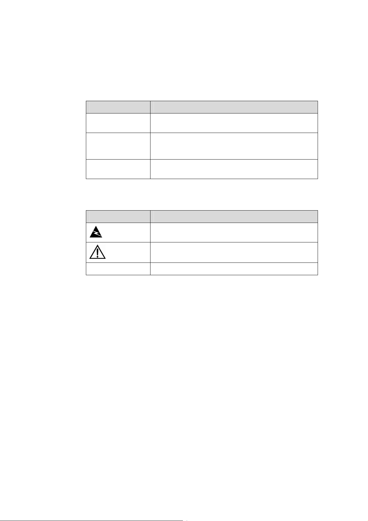
II. Symbols
Convention Description
Means reader be extremely careful. Improper operation
Warning
Caution
Note Means a complementary description.
may cause bodily injury.
Means reader be careful. Improper operation may cause
data loss or damage to equipment.
Environmental Protection
This product has been designed to comply with the requirements on environmental
protection. For the proper storage, use and disposal of this product, national laws and
regulations must be observed.

Installation Manual
H3C S5500-SI Complete Series Ethernet Switches Table of Contents
Table of Contents
Chapter 1 Product Overview........................................................................................................1-1
1.1 Preface...............................................................................................................................1-1
1.2 Introduction to S5500-SI Series Ethernet Switches...........................................................1-3
1.2.1 S5500-28C-SI Ethernet Switch...............................................................................1-3
1.2.2 S5500-52C-SI Ethernet Switch...............................................................................1-4
1.2.3 S5500-28C-PWR-SI Ethernet Switch......................................................................1-5
1.2.4 S5500-52C-PWR-SI Ethernet Switches.................................................................. 1-7
1.2.5 S5500-20TP-SI Ethernet Switch.............................................................................1-8
1.3 Introduction to Front Panel LEDs.....................................................................................1-10
1.3.1 LEDs of S5500-28C-SI/S5500-52C-SI Switch......................................................1-10
1.3.2 LEDs of S5500-28C-PWR-SI/S5500-52C-PWR-SI Switch................................... 1-12
1.3.3 LEDs of S5500-20TP-SI Switch............................................................................1-16
1.4 System Specifications of the S5500-SI Series................................................................1-19
1.5 SFP Modules ................................................................................................................... 1-21
1.6 Optional Interface Modules..............................................................................................1-21
1.6.1 One-port 10 GE XFP Interface Module.................................................................1-22
1.6.2 Dual-Port 10 GE XFP Interface Module................................................................1-22
1.6.3 Short-haul Dual-Port 10 GE CX4 Interface Module..............................................1-23
1.6.4 Description of LEDs of Extension Modules...........................................................1-23
1.7 CX4 Cable........................................................................................................................1-23
Chapter 2 Preparing for Installation............................................................................................ 2-1
2.1 Safety Precautions............................................................................................................. 2-1
2.2 Installation Site...................................................................................................................2-1
2.2.1 Temperature/Humidity.............................................................................................2-1
2.2.2 Cleanness ............................................................................................................... 2-2
2.2.3 Electromagnetic Susceptibility ................................................................................ 2-2
2.2.4 Laser Safety............................................................................................................ 2-3
2.3 Installation Tools................................................................................................................2-3
Chapter 3 Installing the Switch....................................................................................................3-1
3.1 Rack-Mounting the Switch.................................................................................................3-1
3.1.1 Cabinet Mounting.................................................................................................... 3-1
3.1.2 Mounting the Switch on a Workbench .................................................................. 3-10
3.2 Connecting the Power Cords and the Ground Wire........................................................ 3-11
3.2.1 Connecting the AC Power Cord............................................................................3-11
3.2.2 Connecting the DC Power Cord............................................................................ 3-12
3.2.3 Connecting the Ground Wire.................................................................................3-15
3.3 Connecting Optical Fiber.................................................................................................3-17
i

Installation Manual
H3C S5500-SI Complete Series Ethernet Switches Table of Contents
3.4 Connecting Console Cable..............................................................................................3-17
3.4.1 Console Cable....................................................................................................... 3-17
3.4.2 Connecting Console Cable ................................................................................... 3-18
3.5 Installing and Removing Optional Interface Modules...................................................... 3-19
3.5.1 10 GE XFP Interface Module................................................................................3-19
3.5.2 Short-haul Dual-port 10 GE CX4 Interface Module...............................................3-22
3.6 Installing Dedicated CX4 Cable.......................................................................................3-23
3.6.1 Installing Dedicated CX4 Cable ............................................................................ 3-23
3.6.2 Removing Dedicated CX4 Cable .......................................................................... 3-23
3.7 Verifying the Installation................................................................................................... 3-23
Chapter 4 Powering on the Switch for the First Time................................................................4-1
4.1 Setting up the Configuration Environment.........................................................................4-1
4.2 Connecting Console Cable................................................................................................4-1
4.3 Setting Terminal Parameters.............................................................................................4-1
4.4 Booting the Switch............................................................................................................. 4-5
4.4.1 Checking before Powering on the Switch ............................................................... 4-5
4.4.2 Powering on the Switch........................................................................................... 4-5
4.4.3 Changing the Startup Mode.................................................................................... 4-7
Chapter 5 Boot ROM and Host Software Loading ..................................................................... 5-1
5.1 Introduction to Loading Modes .......................................................................................... 5-1
5.2 Local Software Loading.....................................................................................................5-1
5.2.1 Boot Menu...............................................................................................................5-2
5.2.2 Loading Software Using XMODEM Through Console Port....................................5-3
5.2.3 Loading Software Using TFTP through Ethernet Port............................................5-8
5.2.4 Loading Software Using FTP Through Ethernet Port............................................. 5-9
5.3 Remote Software Loading...............................................................................................5-11
5.3.1 Remote Loading Using FTP..................................................................................5-11
5.3.2 Remote Loading Using TFTP................................................................................5-13
Chapter 6 Maintenance and Troubleshooting............................................................................6-1
6.1 Software Loading Failure...................................................................................................6-1
6.2 Password Missing Failure..................................................................................................6-1
6.2.1 Missing User Password........................................................................................... 6-1
6.2.2 Missing Boot ROM Password ................................................................................. 6-2
6.3 Power Supply Failure......................................................................................................... 6-2
6.4 Configuration System Failure ............................................................................................ 6-2
ii
Installation Manual
H3C S5500-SI Complete Series Ethernet Switches Chapter 1 Product Overview
Chapter 1 Product Overview
1.1 Preface
H3C S5500-SI Series Ethernet switches (hereinafter referred to as S5500-SI series)
are Gigabit Ethernet switching products developed by H3C.
Currently, S5500-SI Series Ethernet switches include the S5500-28C-SI,
S5500-52C-SI, S5500-28C-PWR-SI, S5500-52C-PWR-SI, and S5500-20TP-SI, as
listed in the following table:
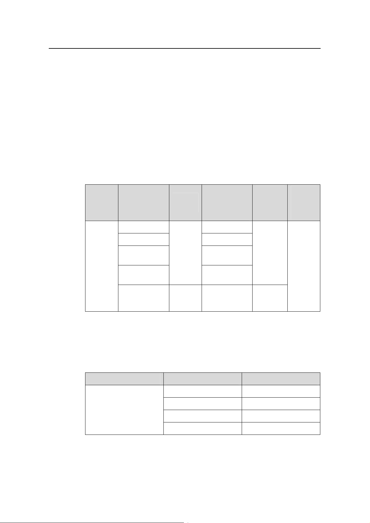
Table 1-1 H3C S5500-SI Series Ethernet switches
Number of
Name Model
S5500-28C-SI 24
S5500-52C-SI 48
H3C
S5500-SI
Series
Ethernet
switches
Each SFP port and the corresponding 10/100/1000BASE-T Ethernet port form a
Combo port. For each Combo port, either the SFP port or the corresponding
10/100/1000BASE-T Ethernet port can be used at a time. Refer to
Table 1-2 Combo port mapping relationship
S5500-28C-PW
R-SI
S5500-52C-PW
R-SI
S5500-20TP-SI AC input 8
Power
supply
AC input
or RPS
DC input
10/100/1000
Mbps
electrical ports
24
48
Number
of gigabit
uplink
ports
Four
Gigabit
SFP
Combo
ports
Twelve
Gigabit
SFP ports
Table 1-2.
Number
of
Console
ports
1
Model Combo port Corresponding port
S5500-28C-SI
S5500-28C-PWR-SI
25 22
26 24
27 21
28 23
1-1

Installation Manual
H3C S5500-SI Complete Series Ethernet Switches Chapter 1 Product Overview
Model Combo port Corresponding port
49 46
S5500-52C-SI
S5500-52C-PWR-SI
50 48
51 45
52 47
Note:
A Gigabit Combo port and its corresponding 10/100/1000BASE-T autosensing
Ethernet port cannot be used together at the same time. For details, refer to the Port
Correlation Configuration part of the H3C S5500-SI Series Ethernet Switches
Operation Manual.
S5500-SI series have abundant service features. They provide the IPv6 forwarding
function and 10GE uplink interfaces, and support H3C-specific cluster management,
which simplifies your network management. S5500-SI series are designed as
convergence and access devices for enterprise networks and metropolitan area
networks (MANs), and can also be used for connecting server group s in d ata centers.
The feature-rich S5500-SI series switches support the following services:
z Broadband Internet access
z Access of MAN and enterprise network users
z Multimedia services, such as VoD
z Delay-sensitive voice services, such as VoIP
z Multicast audio and video services
S5500-SI series feature the following advantages:
z Providing full-Gigabit access ports
z Providing 10GE ports (except for the S5500-20TP-SI switch)
z Supporting IPv4/IPv6 dual-stack and hardware forwarding
z Supporting jumbo frames
z Supporting port security
z Supporting link aggregation control protocol (LACP)
z Supporting 4K VLANs
z Supporting QACL
z Supporting port-based/flow-based mirroring
1-2
Installation Manual
H3C S5500-SI Complete Series Ethernet Switches Chapter 1 Product Overview
1.2 Introduction to S5500-SI Series Ethernet Switches
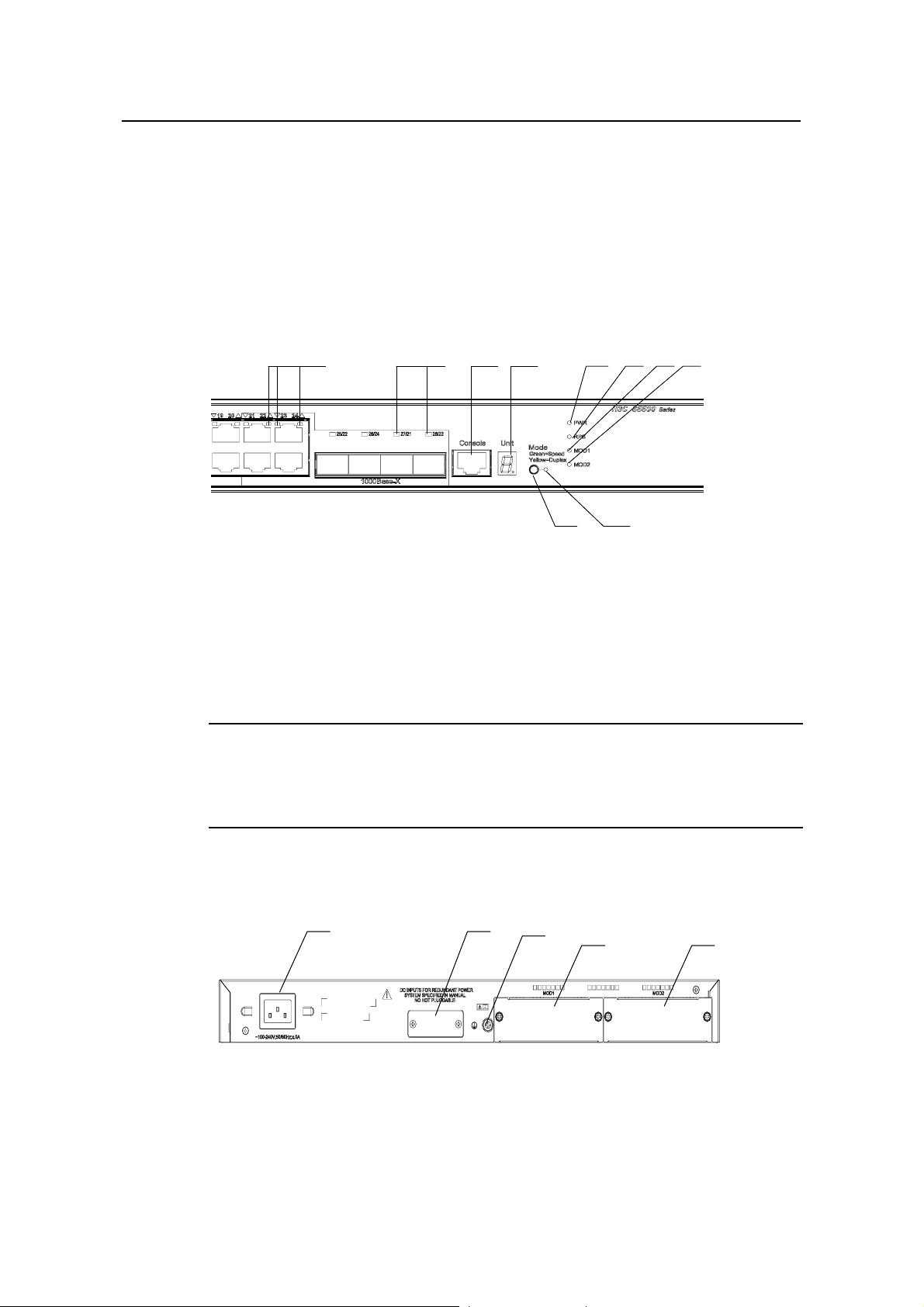
1.2.1 S5500-28C-SI Ethernet Switch
I. Front Panel
The S5500-28C-SI Ethernet switch provides 24 × 10/100/1000BA SE-T Ethernet ports,
four Gigabit SFP Combo ports and one Console port on the front panel.
shows the front panel appearance of the S5500-28C-SI Ethernet switch.
(2) (3) (4) (5) (6) (7) (8)
(1)
(1)
(1): 10/100/1000 BASE-T autosensing Ethernet port status LED
(2): Gigabit SFP Combo port status LED
(3): Console port (4): 7-segment digitron display
(5): Power LED (6): DC power LED
(7): LED for extended slot 1 (8): LED for extended slot 2
(9): Mode LED (10): Mode switching button
(2) (3) (4) (5) (6) (7) (8)
(9)
(10)
(10)
(9)
Figure 1-1
Figure 1-1 Front panel of the S5500-28C-SI Ethernet switch
Note:
For details about LEDs on the front panel, refer to section 1.3.1 “LEDs of
S5500-28C-SI/S5500-52C-SI Switch”.
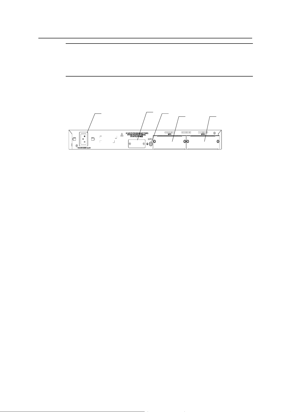
II. Rear Panel
(1) (2)
(1) (2)
(3)
(3)
(4)
(4)
(5)
(5)
(1): AC power input (2): DC power input
(3): Grounding screw (4): Extended slot 1
(5): Extended slot 2
Figure 1-2 Rear panel of the S5500-28C-SI Ethernet switch
1-3
Installation Manual
H3C S5500-SI Complete Series Ethernet Switches Chapter 1 Product Overview
III. Power Supply System
The S5500-28C-SI Ethernet switch supports both AC input and RPS 12 V input. The
AC input and DC input can be used together to serve as backup for each other. In
addition, either of them can be used alone. You can use only the RPS power supply
recommended by H3C for DC input.
AC input:
Rated voltage range: 100 VAC to 240 VAC, 50 Hz or 60 Hz
Input voltage range: 90 VAC to 264 VAC, 50 Hz or 60 Hz
RPS (DC) input:
Rated voltage range: 10.8 VDC to 13.2 VDC
IV. Cooling System
The S5500-28C-SI Ethernet switch provides four fans for heat dissipation.
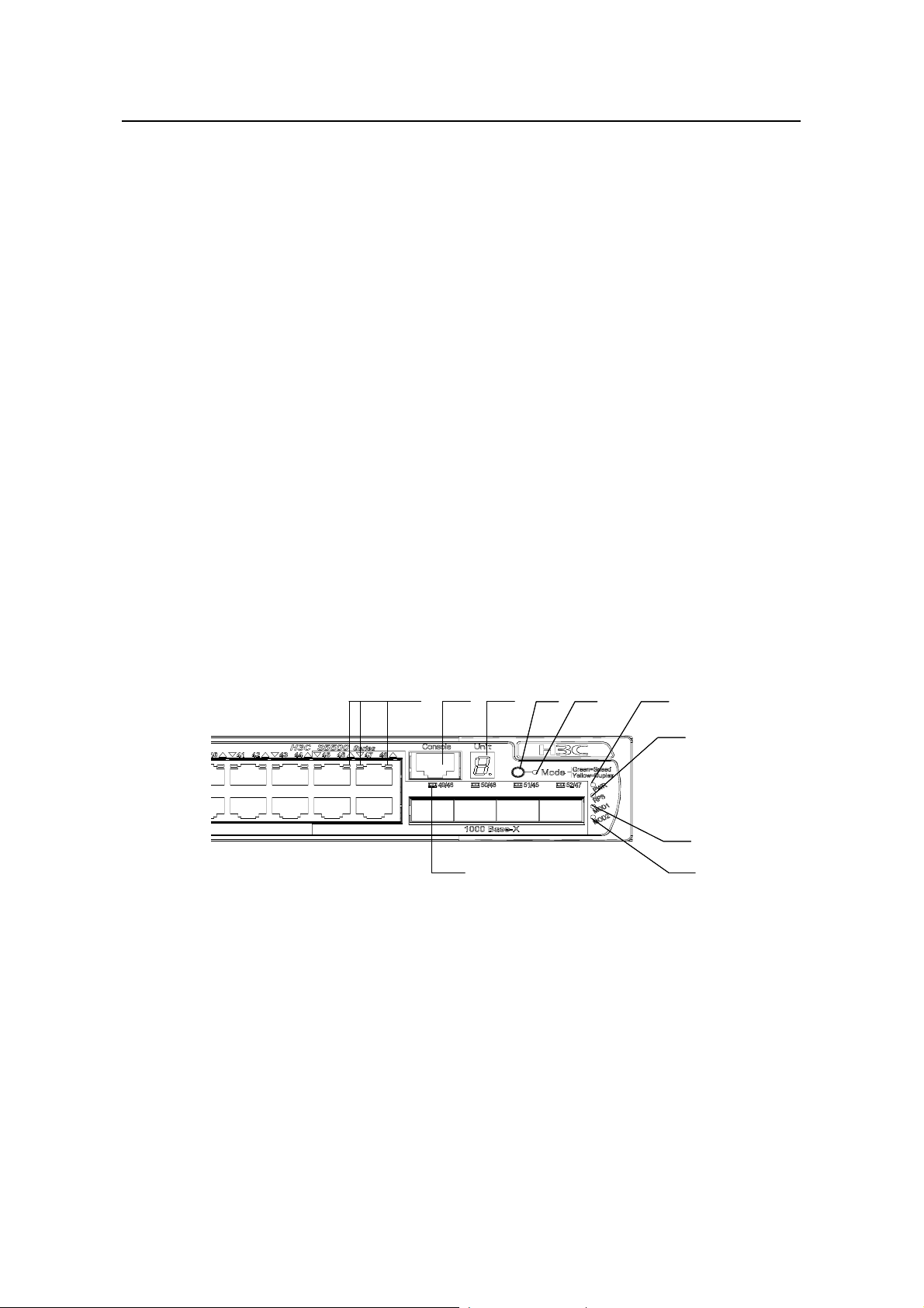
1.2.2 S5500-52C-SI Ethernet Switch
I. Front Panel
The S5500-52C-SI Ethernet switch provides 48 × 10/100/1000BA SE-T Ethernet ports,
four Gigabit SFP Combo ports and one Console port on the front panel.
Figure 1-3
shows the front panel appearance of the S5500-52C-SI Ethernet switch.
(1) (2)
(1) (2)
(10)
(10)
(3) (6)
(3) (6)
(4) (5)
(4) (5)
(7)
(7)
(8)
(8)
(9)
(9)
(1): 10/100/1000 BASE-T autosensing Ethernet port status LEDs
(2): Console port (3): 7-segment digitron display
(4): Mode switching button (5): Mode LED
(6): Power LED (7): DC Power LED
(8): LED for extended slot 1 (9): LED for extended slot 2
(10): Gigabit SFP Combo port status LED
Figure 1-3 Front panel of the S5500-52C-SI Ethernet switch
1-4
Installation Manual
H3C S5500-SI Complete Series Ethernet Switches Chapter 1 Product Overview
Note:
For details about LEDs on the front panel, refer to section 1.3.1 “LEDs of
S5500-28C-SI/S5500-52C-SI Switch”.
II. Rear Panel
(1)
(1)
(2)
(3)
(3)
(4)
(4)
(5)
(5)
(2)
(1): AC power input (2): DC power input
(3): Grounding screw (4): Extended slot 1
(5): Extended slot 2
Figure 1-4 Rear panel of the S5500-52C-SI Ethernet switch
III. Power Supply System
The S5500-52C-SI Ethernet switch supports both AC input and RPS 12 V input. The
AC input and DC input can be used together to serve as backup for each other. In
addition, either of them can be used alone. You can use only the RPS power supply
recommended by H3C for DC input.
AC power input:
Rated voltage range: 100 VAC to 240 VAC, 50 Hz or 60 Hz
Input voltage range: 90 VAC to 264 VAC, 50 Hz or 60 Hz
RPS (DC) input:
Rated voltage range: 10.8 VDC to 13.2 VDC
IV. Cooling System
The S5500-52C-SI Ethernet switch provides four fans for heat dissipation.
1.2.3 S5500-28C-PWR-SI Ethernet Switch
I. Front Panel
The S5500-28C-PWR-SI Ethernet switch provides 24 × 10/100/1000Base-T Ethernet
ports, four Gigabit SFP Combo ports and one Console port on the front panel.
Figure
1-5 shows the front panel appearance of the S5500-28C-PWR-SI Ethernet switch.
1-5
Installation Manual
H3C S5500-SI Complete Series Ethernet Switches Chapter 1 Product Overview
(2) (3) (4) (5) (6) (7) (8)
(2) (3) (4) (5) (6) (7) (8)
(2) (3) (4) (5) (6) (7) (8)
(1)
(1)
(1)
(1)
(2) (3) (4) (5) (6) (7) (8)
(9)
(9)
(9)
(10)
(10)
(10)
(10)
(9)
(1): 10/100/1000 BASE-T autosensing Ethernet port status LEDs
(2): Gigabit SFP Combo port status LED
(3): Console port (4): 7-segment digitron display
(5): Power LED (6): DC Power LED
(7): LED for extended slot 1 (8): LED for extended slot 2
(9): Mode LED (10): Mode switching button
Figure 1-5 Front panel of the S5500-28C-PWR-SI Ethernet switch
Note:
For details about LEDs on the front panel, refer to section 1.3.2 “LEDs of
S5500-28C-PWR-SI/S5500-52C-PWR-SI Switch”.
II. Rear Panel
(1) (2)
(1) (2)
(3)
(3)
(4)
(4)
(5)
(5)
(1): DC power input (2): AC power input
(3): Grounding screw (4): Extended slot 1
(5): Extended slot 2
Figure 1-6 Rear panel of the S5500-28C-PWR-SI Ethernet switch
III. Power Supply System
The S5500-28C-PWR-SI Ethernet switch supports both AC input and DC input. The AC
input and DC input can be used together to serve as backup for each other . In addition,
either of them can be used alone.
AC power input:
Rated voltage range: 100 VAC to 240 VAC, 50 Hz or 60 Hz
1-6
Installation Manual
H3C S5500-SI Complete Series Ethernet Switches Chapter 1 Product Overview
Input voltage range: 90 VAC to 264 VAC, 50 Hz or 60 Hz
The S5500-28C-PWR-SI Ethernet switch supports only the external PoE power supply
recommended by H3C as the DC power. –48 VDC power cannot be used directly.
Otherwise, the device may be destroyed.
DC input:
Rated voltage range: –52 VDC to –55 VDC
IV. Cooling System
The S5500-28C-PWR-SI Ethernet switch provides six fans for heat dissipation.
1.2.4 S5500-52C-PWR-SI Ethernet Switches
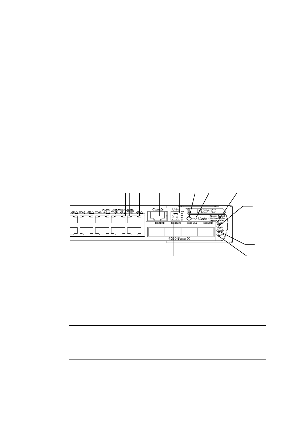
I. Front Panel
The S5500-52C-PWR-SI Ethernet switch provides 48 × 10/100/1000Base-T Ethernet
ports, four Gigabit SFP Combo ports and one Console port on the front panel.
1-7 shows the front panel appearance of the S5500-52C-PWR-SI Ethernet switch.
Figure
(1) (2)
(1): 10/100/1000 BASE-T autosensing Ethernet port status LEDs
(2): Console port (3): 7-segment digitron display
(4): Mode switching button (5): Mode LED
(6): Power LED (7): DC Power LED
(8): LED for extended slot 1 (9): LED for extended slot 2
(10): Gigabit SFP Combo port status LED
(3) (6)
(4) (5) (1) (2)
(3) (6)
(4) (5) (1) (2)
(3) (6)
(4) (5) (1) (2)
(3) (6)
(4) (5)
(10 )
(10 )
(10 )
(10 )
Figure 1-7 Front panel of the S5500-52C-PWR-SI Ethernet switch
Note:
(7)
(7)
(7)
(7)
(8 )
(8 )
(8 )
(8 )
(9 )
(9 )
(9 )
(9 )
For details about LEDs on the front panel, refer to section 1.3.2 “LEDs of
S5500-28C-PWR-SI/S5500-52C-PWR-SI Switch”.
1-7

Installation Manual
H3C S5500-SI Complete Series Ethernet Switches Chapter 1 Product Overview
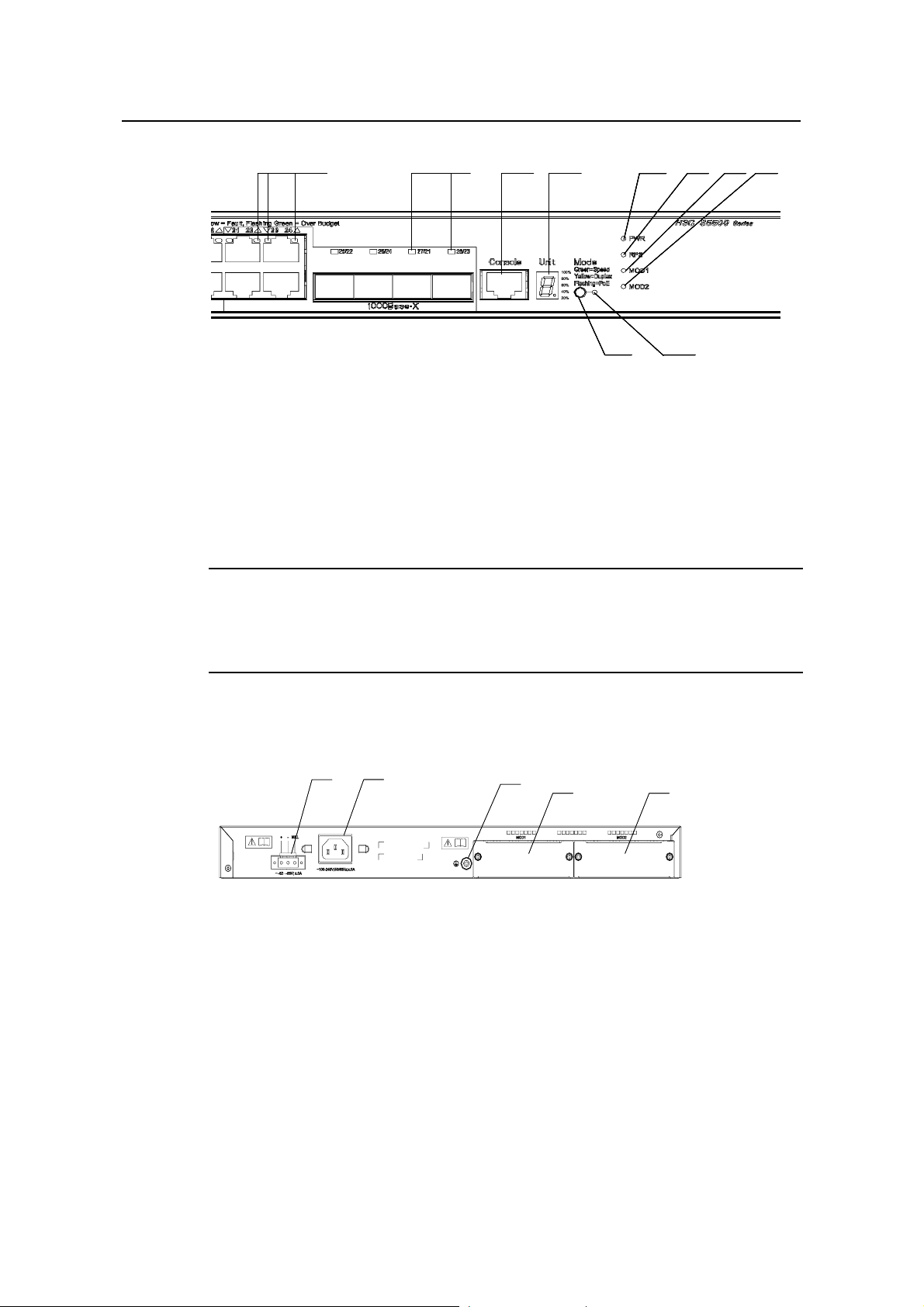
II. Rear Panel
(1) (2 )
(1) (2 )
(3)
(3)
(4)
(4)
(5)
(5)
(1): DC power input (2): AC power input
(3): Grounding screw (4): Extended slot 1
(5): Extended slot 2
Figure 1-8 Rear panel of the S5500-52C-PWR-SI Ethernet switch
III. Power Supply System
The S5500-52C-PWR-SI Ethernet switch supports both AC input and DC input. The AC
input and DC input can be used together to serve as backup for each other . In addition,
either of them can be used alone.
AC power input:
Rated voltage range: 100 VAC to 240 VAC, 50 Hz or 60 Hz
Input voltage range: 90 VAC to 264 VAC, 50 Hz or 60 Hz
The S5500-52C-PWR-SI Ethernet switch supports only the external PoE power supply
recommended by H3C as the DC power. –48 V DC power cannot be used directly.
Otherwise, the device may be destroyed.
DC input:
Rated voltage range: –52 VDC to –55 VDC
IV. Cooling System
The S5500-52C-PWR-SI Ethernet switch provides six fans for heat dissipation.
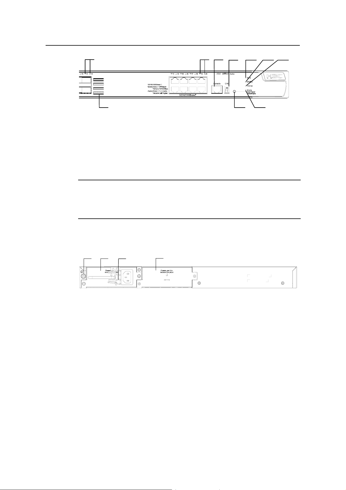
1.2.5 S5500-20TP-SI Ethernet Switch
I. Front panel
The S5500-20TP-SI Ethernet switch provides 12 Gigabit SFP ports, 8 ×
10/100/1000Base-T Ethernet ports, and one console port on the front panel.
shows the front panel appearance of the S5500-20TP-SI Ethernet switch.
Figure 1-9
1-8
Installation Manual
H3C S5500-SI Complete Series Ethernet Switches Chapter 1 Product Overview
(1)
(2)
(3)
(4)
(5)
(6)
(7)
(10)
(9)
(8)
(1): 1000/100 Mbps SFP port LED (2): 10/100/1000 Base-T autosensing Ethernet port LED
(3): Console port (4): 7-segment digitron display
(5): System LED (6): LED for power slot 1
(7): LED for power slot 2 (8): Mode LED
(9): Mode switching button (10): Air intake vent
Figure 1-9 Front panel of the S5500-20TP-SI Ethernet switch
Note:
For details about LEDs on the front panel, refer to section 1.3.3 LEDs of
S5500-20TP-SI Switch.
II. Rear panel
(1)
(2)
(3)
(4)
(1): Grounding screw (2): Power slot 1
(3): Power cable bail latch (4): Power slot 2
Figure 1-10 Rear panel of the S5500-20TP-SI Ethernet switch
III. Power supply system
The S5500-20TP-SI Ethernet switch adopts AC input.
Rated voltage range: 100 VAC to 240 VAC, 50 Hz or 60 Hz
Input voltage range: 90 VAC to 264 VAC, 50 Hz or 60 Hz
IV. Cooling system
The S5500-20TP-SI Ethernet switch provides five fans (three for the system, and one
for each power module) for heat dissipation.
1-9

Installation Manual
H3C S5500-SI Complete Series Ethernet Switches Chapter 1 Product Overview
1.3 Introduction to Front Panel LEDs
1.3.1 LEDs of S5500-28C-SI/S5500-52C-SI Switch
The S5500-28C-SI/S5500-52C-SI Ethernet switch provides LEDs on the front panel for
your convenience to monitor the switch.
You can use the mode button on the panel to switch the display mode (rate mode or
duplex mode) of LEDs.
Table 1-3 Description on the LEDs of the S5500-28C-SI/S5500-52C-SI Ethernet
switch
LED Mark Status Description
Table 1-3 describe s the meanings of the LEDs.
Mode LED Mode
Power LED PWR
DC power LED RPS
Rate
mode
Duplex
mode
Green, ON The switch starts normally.
Green, blinking (1
Hz)
Red, ON The system fails the POST.
Yellow, blinking (1
Hz)
OFF The switch is powered off.
Green, ON
Yellow, ON
OFF
Green,
ON
Yellow,
ON
The port status LEDs are
showing the port rates.
The port status LEDs are
showing the duplex mode of
the ports.
The system is performing
power-on self test (POST).
One or more ports fail the
POST.
Both AC and DC inputs are
normal.
The DC input is normal, but
the AC input is abnorm al or
disconnected.
The DC input is
disconnected.
Module LED
Module(
MOD)
Green, ON
Yellow, blinking
OFF The module is not installed.
1-10
The module is installed and
operates normally.
The module is not supported
or is in trouble.
Installation Manual
H3C S5500-SI Complete Series Ethernet Switches Chapter 1 Product Overview
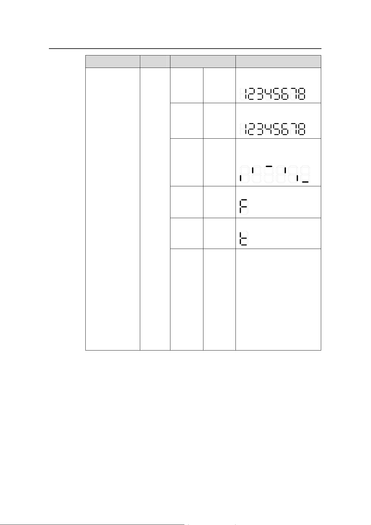
LED Mark Status Description
The POST ID of the
POST
running
Green,
blinking
in-process test is displayed.
The POST ID of the failed
POST
failed
Red,
blinking
test blinks.
A light bar rotates clockwise
around the display during
Loading
software
Green,
blinking
the loading procedure.
7-segment
digitron display
Unit
Fan
failure
Overtem
perature
alarm
Cluster
status
Red, ON
Red, ON
Green,
ON
An “F” is displayed.
A “t” is displayed.
A “C” is displ ayed if this is a
command switch.
An “S” is displayed if this is a
member switch.
A “c” is displayed if this is a
candidate switch.
A “1” is displayed when the
switch operates
independently.
(The default display is “c”,
that is, the device is
candidate switch by default.)
1-11

Installation Manual
H3C S5500-SI Complete Series Ethernet Switches Chapter 1 Product Overview
LED Mark Status Description
The port works at the rate of
Green
1000 Mbps; the LED blinks
quickly when the port is
sending or receiving data.
The port works at the rate of
Rate
mode
Yellow
10/100 Mbps; the LED blinks
quickly when the port is
sending or receiving data.
Yellow,
blinking
POST fails on the port.
(3 Hz)
10/100/1000BAS
E-T Ethernet port
status LED
1000Base SFP
port status LED
—
—
Duplex
mode
This LED
is not
influence
d by the
mode
button
OFF The port is not connected.
The port works in full duplex
Green
mode; the LED blinks quickly
when the port is sending or
receiving data..
The port works in half duplex
Yellow
mode; the LED blinks quickly
when the port is sending or
receiving data..
Yellow,
blinking
POST fails on the port.
(3 Hz)
OFF The port is not connected.
The port works at the rate of
Green
1000 Mbps; the LED blinks
quickly when the port is
sending or receiving data.
Yellow,
blinking
POST fails on the port.
(3 Hz)
OFF The port is not connected.
1.3.2 LEDs of S5500-28C-PWR-SI/S5500-52C-PWR-SI Switch
The S5500-28C-PWR-SI/S5500-52C-PWR-SI Ethernet switch provides LEDs on the
front panel for your convenience to monitor the switch.
meanings of the LEDs. You can use the Mode button on the panel to swit ch the display
mode (rate mode, duplex mode, or PoE mode) of LEDs.
1-12
Table 1-4 describes the

Installation Manual
H3C S5500-SI Complete Series Ethernet Switches Chapter 1 Product Overview
Table 1-4 Description on the LEDs of the S5500-28C-PWR-SI/S5500-52C-PWR-SI
Ethernet switch
LED Mark Status Description
Mode LED Mode
Power LED PWR
DC power LED RPS
Rate mode
Duplex
mode
PoE mode
Green,
ON
Yellow,
ON
Green,
blinking
(1 Hz)
The port status LEDs are
showing the port rate.
The port status LEDs are
showing the duplex mode of the
port.
The port status LEDs are
showing the PoE status of the
port.
Green, ON The switch starts normally.
Green, blinking (1
Hz)
The system is performing
power-on self test (POST).
Red, ON The POST fails the POST.
Yellow, blinking (1
Hz)
One or more ports fail the
POST.
OFF The switch is powered off.
Green, ON
Both AC and DC inputs are
normal.
The DC input is normal but the
Yellow, ON
AC input is abnormal or
disconnected.
Module LED
Module
(MOD)
OFF The DC input is disconnected.
Green, ON
Yellow, blinking
The module is installed and
operates normally.
The module is not supported or
is in trouble.
OFF The module is not installed.
1-13
Installation Manual
H3C S5500-SI Complete Series Ethernet Switches Chapter 1 Product Overview
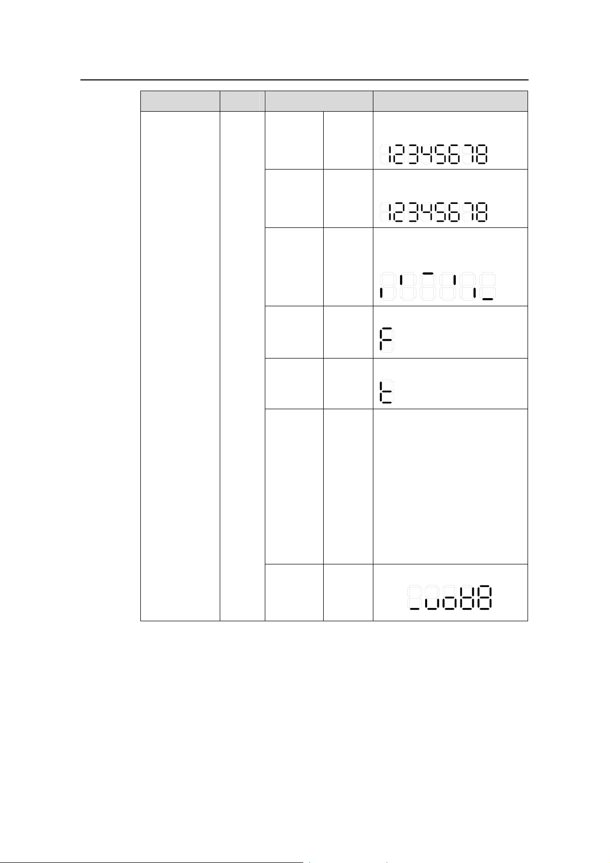
LED Mark Status Description
The POST ID of the in-process
POST
running
Green,
blinking
test is displayed.
The POST ID of the failed test
POST
failed
Red,
blinking
blinks.
A light bar rotates clockwise
around the display during the
Loading
software
Green,
blinking
loading procedure.
7-segment
digitron display
Unit
Fan
failure
Overtemp
erature
alarm
Cluster
status
PoE mode
Red,
ON
Red,
ON
Green,
ON
Green,
ON
An “F” is displayed.
A “t” is displayed.
A “C” is displ ayed if there is a
command switches.
An “S” is displayed if there is a
member switches.
A “c” is displayed if there is a
candidate switches.
A “1” is displayed when the
switch operates independently.
(The default display is “c”, that
is, the device is candidate
switch by default.)
Show the utilization of the
power
81 - 100%
61 - 80%
41 - 60%
21 - 40%
0 - 20%
1-14

Installation Manual
H3C S5500-SI Complete Series Ethernet Switches Chapter 1 Product Overview
LED Mark Status Description
The port works at the rate of
Green
1000 Mbps; the LED blinks
quickly when the port is sending
or receiving data.
The port works at the rate of
Rate
mode
Yellow
10/100 Mbps; the LED blinks
quickly when the port is sending
or receiving data.
Yellow,
blinking
POST fails on the port.
(3 Hz)
OFF The port is not connected.
The port works in full duplex
Green
mode; the LED blinks quickly
when the port is sending or
receiving data.
The port works in half duplex
Duplex
mode
Yellow
mode; the LED blinks quickly
when the port is sending or
receiving data.
10/100/1000B
ASE-T
Ethernet port
status LED
—
PoE mode
Yellow,
blinking
POST fails on the port.
(3 Hz)
OFF The port is not connected.
Green,
ON
The port supplies power
normally
The required power of the
attached devices has exceeded
the maximum power that the
Green,
blinking
(1 Hz)
port can supply.
The total power that the switch
supplies has reached the
maximum power, so the port
does not supply power any
more.
The devices attached to the port
are not powered devices (PDs),
Yellow,
ON
so the port does not supply
power.
The PoE power fails, so the port
cannot supply power.
1-15
Yellow,
blinking
POST fails on the port
(3 Hz)
OFF The port does not supply power.

Installation Manual
H3C S5500-SI Complete Series Ethernet Switches Chapter 1 Product Overview
LED Mark Status Description
The port works at the rate of
1000 Mbps; the LED blinks
quickly when the port is sending
or receiving data.
POST fails on the port.
1000Base SFP
port status
LED
—
This LED
is not
influenced
by the
mode
button
Green
Yellow,
blinking
(3 Hz)
OFF The port is not connected.
1.3.3 LEDs of S5500-20TP-SI Switch
The S5500-20TP-SI Ethernet switch provides LEDs on the front panel for your
convenience to monitor the switch.
can use the Mode button on the panel to switch the display mode (rate mode, or duplex
mode) of LEDs.
Table 1-5 describe s the meanings of the LEDs. You
Table 1-5 Description of LEDs on the front panel of the S5500-20TP-SI Ethernet
Switch
LED Mark Status Description
Speed
Solid
green
Rate of the port
Mode LED Mode
Solid
yellow
Duplex of the port
The switch is started
normally.
The system is running a
POST.
The system fails the POST
or a power failure occurs.
Some ports fail the POST or
a port failure occurs.
System power
LED
SYS
Duplex
Solid green
Flashing green (1 Hz)
Solid red
Flashing yellow (1
Hz)
OFF The power is disconnected.
A power module is installed
Solid green
in the power module slot and
the output is normal.
LED for power
module slot 1
PWR1
Solid yellow
OFF
1-16
A power module is installed
in the power module slot but
there is an output failure.
No power module is installed
in the power module slot or
no power is input.
Installation Manual
H3C S5500-SI Complete Series Ethernet Switches Chapter 1 Product Overview
LED Mark Status Description
A power module is installed
Solid green
in the power module slot and
the output is normal.
LED for power
module slot 2
PWR2
Module LED MOD
A power module is installed
Solid yellow
in the power module slot but
there is an output failure.
No power module is installed
OFF
in the power module slot or
no power is input.
Solid green
The module is in position
and works normally.
The switch does not support
Flashing yellow
the module or a module
failure occurs.
OFF No module is installed.
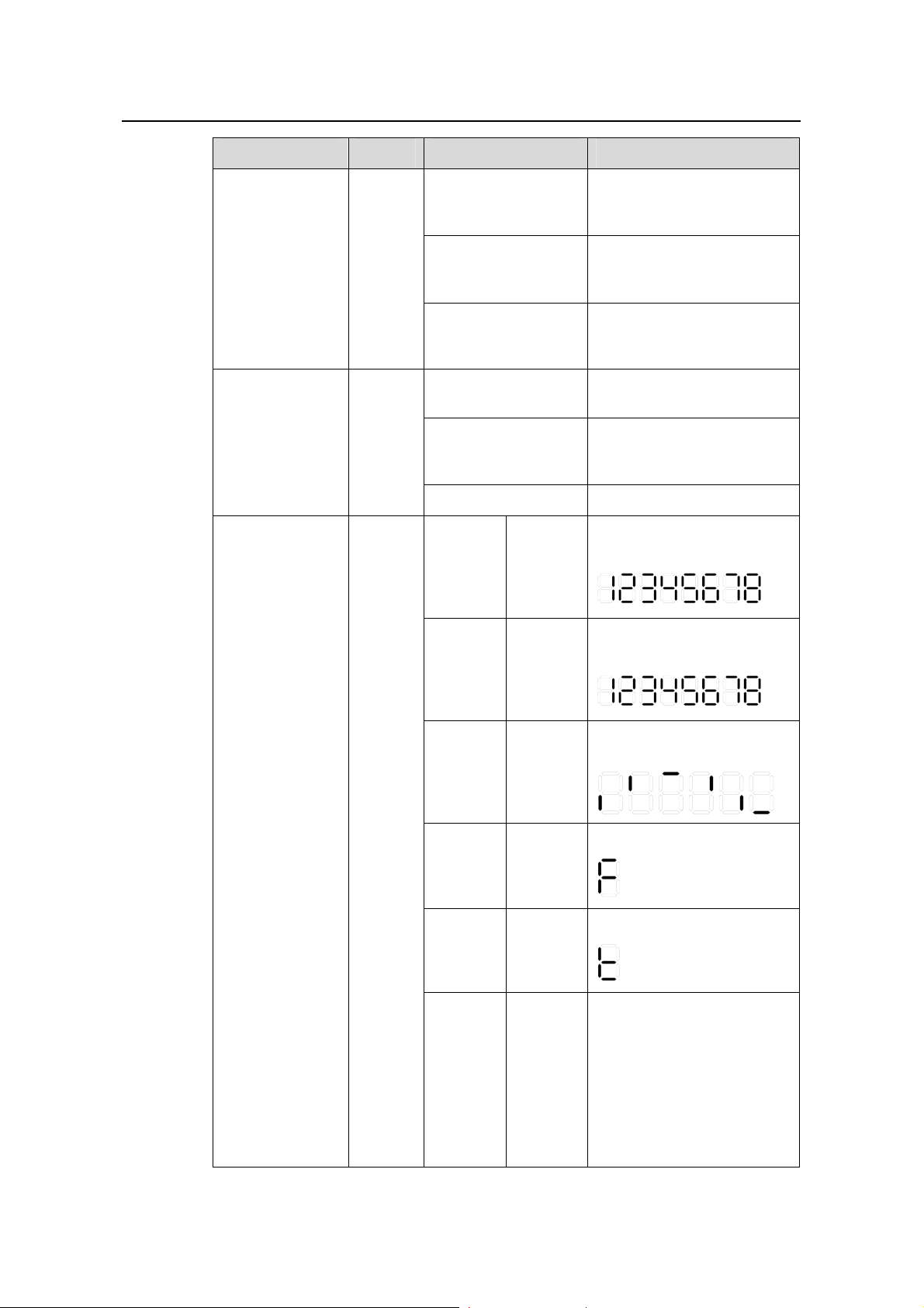
POST
running
The
power
LED
flashes
The LED displays the POST
test ID.
green.
POST
failed
The
power
LED
flashes
The LED flashes the POST
test ID of the failed test.
red.
7-segment digital
LED
Unit
Software
loading
Fan
failure
Over-tem
perature
alarm
Cluster
status
The
power
LED
flashes
green.
The
power
LED is
solid red.
The
power
LED is
solid red.
Solid
green
A bar rotates clockwise
around the LED.
The LED displays F.
The LED displays t.
For a command switch, the
LED displays C.
For a member switch, the
LED displays S.
For a candidate switch, the
LED displays c.
The LED displays 1 if there
is only one unit.
1-17

Installation Manual
H3C S5500-SI Complete Series Ethernet Switches Chapter 1 Product Overview
LED Mark Status Description
A 1000 Mbps link is present.
Green
When data is being received
or sent, the LED flashes at a
high frequency.
A 10/100 Mbps link is
Speed
Yellow
present. When data is being
received or sent, the LED
flashes at a high frequency.
Flashing
yellow (3
The port fails the POST.
Hz)
Auto-sensing
10/100/1000Bas
e-T Ethernet port
status LED
SFP port status
LED (1000
Mbps)
—
—
Duplex
The
Mode
button
has no
effect on
the LED.
OFF No link is present.
The port operates in the full
duplex mode. When data is
Green
being received or sent, the
LED flashes at a high
frequency.
The port operates in the half
duplex mode. When data is
Yellow
being received or sent, the
LED flashes at a high
frequency.
Flashing
yellow (3
The port fails the POST.
Hz)
OFF No link is present.
A 1000 Mbps link is present.
Green
When data is being received
or sent, the LED flashes
every 30 milliseconds.
Flashing
yellow (3
The port fails the POST.
Hz)
OFF No link is present.
1-18

Installation Manual
H3C S5500-SI Complete Series Ethernet Switches Chapter 1 Product Overview
1.4 System Specifications of the S5500-SI Series
Table 1-6 System specifications of the S5500-SI series
Item
Physical
dimensions
(H × W × D)
Weight
Management
port
GE ports on
the front
panel
Optional
interface
modules
S5500-28C-
SI
43.6 × 440 × 300 mm (1.72
× 17.3 × 11.8 in.)
4 kg (8.8 lb)
One console port
24 ×
10/100/1000
Mbps
electric ports
Four Gigabit
SFP Combo
ports
One-port 10 GE XFP interface module
Dual-port 10 GE XFP interface module
Short-haul dual-port 10GE CX4 interface module
S5500-52C
-SI
4.5 kg (9.9
lb)
48 ×
10/100/100
0 Mbps
electric
ports
Four
Gigabit
SFP
Combo
ports
S5500-28C-PWR
-SI
43.6 × 440 × 420 mm (1.72 × 17.3 ×
16.5 in.)
6 kg (13.2 lb) 6.5 kg (14.3 lb)
24 × 10/100/1000
Mbps electric
ports
Four Gigabit SFP
Combo ports
S5500-52C-PW
R-SI
48 ×
10/100/1000
Mbps electric
ports
Four Gigabit SFP
Combo ports
Input
volta
ge
Power
consumption
(full load)
AC
DC
Rated voltage range: 100 VAC to 240 VAC, 50 Hz or 60 Hz
Input voltage range: 90 VAC to 264 VAC, 50 Hz or 60 Hz
Rated voltage range:
10.8 VDC to 13.2 VDC
80 W
120 W
Rated voltage range:
–52 VDC to –55 VDC
455 W, with 85 W
of system power
consumption and
370 W of PoE
power
500 W when
RPS is not
connected, with
130 W of system
power
consumption and
370 W of PoE
power
870 W when
RPS is
connected, with
130 W of system
power
consumption and
740 W of PoE
power
1-19
Installation Manual
H3C S5500-SI Complete Series Ethernet Switches Chapter 1 Product Overview
Item
S5500-28C-
SI
S5500-52C
-SI
S5500-28C-PWR
-SI
S5500-52C-PW
R-SI
Operating
temperature
0°C to 45°C (32°F to 113°F)
Relative
humidity
(noncondens
ing)
10% to 90%
Table 1-7 System specifications of the S5500-20TP-SI Ethernet switch
Item S5500-20TP-SI
Physical
dimensions
(H × W × D)
Weight
Management
port
GE ports on
the front
panel
43.6 × 440 × 360 mm (1.72 × 17.3 × 14.2 in.)
5.5 kg (12.1 lb)
One console port
12 Gigabit SFP Combo ports
8 × 10/100/1000 Mbps electric ports
Optional
interface
modules
Input
AC
volta
ge
DC
Power
consumption
(full load)
Operating
temperature
Relative
humidity
(noncondens
ing)
Interface modules not supported
Rated voltage range: 100 VAC to 240 VAC, 50 or 60 Hz
Input voltage range: 90 VAC to 264 VAC, 50 or 60 Hz
Not supported
65 W
0°C to 45°C (32°F to 113°F)
10% to 90%
1-20
 Loading...