

Page 1

Switch 7700
Configuration Guide
http://www.3com.com/
Published October 2003
Page 2

3Com Corporation
350 Campus Drive
Marlborough, MA
01752-3064
Copyright © 2003, 3Com Corporation. All rights reserved. No part of this documentation may be reproduced
in any form or by any means or used to make any derivative work (such as translation, transformation, or
adaptation) without written permission from 3Com Corporation.
3Com Corporation reserves the right to revise this documentation and to make changes in content from time
to time without obligation on the part of 3Com Corporation to provide notification of such revision or change.
3Com Corporation provides this documentation without warranty, term, or condition of any kind, either
implied or expressed, including, but not limited to, the implied warranties, terms or conditions of
merchantability, satisfactory quality, and fitness for a particular purpose. 3Com may make improvements or
changes in the product(s) and/or the program(s) described in this documentation at any time.
If there is any software on removable media described in this documentation, it is furnished under a license
agreement included with the product as a separate document, in the hard copy documentation, or on the
removable media in a directory file named LICENSE.TXT or !LICENSE.TXT. If you are unable to locate a copy,
please contact 3Com and a copy will be provided to you.
UNITED STATES GOVERNMENT LEGEND
If you are a United States government agency, then this documentation and the software described herein
are provided to you subject to the following:
All technical data and computer software are commercial in nature and developed solely at private expense.
Software is delivered as “Commercial Computer Software” as defined in DFARS 252.227-7014 (June 1995)
or
as a “commercial item” as defined in FAR 2.101(a) and as such is provided with only such rights as are
provided in 3Com’s standard commercial license for the Software. Technical data is provided with limited
rights only as provided in DFAR 252.227-7015 (Nov
applicable. You agree not to remove or deface any portion of any legend provided on any licensed program
or documentation contained in, or delivered to you in conjunction with, this User Guide.
Unless otherwise indicated, 3Com registered trademarks are registered in the United States and may or may
not be registered in other countries.
3Com, the 3Com logo, are registered trademarks of 3Com Corporation.
Intel and Pentium are registered trademarks of Intel Corporation. Microsoft, MS-DOS, Windows, and
Windows NT are registered trademarks of Microsoft
States and other countries, licensed exclusively through X/Open Company, Ltd.
All other company and product names may be trademarks of the respective companies with which they are
associated.
1995) or FAR 52.227-14 (June 1987), whichever is
Corporation. UNIX is a registered trademark in the United
Page 3

CONTENTS
ABOUT THIS GUIDE
Conventions 1
SYSTEM ACCESS
Product Overview 3
Function Features 3
Configuring the Switch 7700 4
Setting Terminal Parameters 5
Configuring Through Telnet 8
Configuring Through a Dial-up the Modem 10
Configuring the User Interface 12
Command Line Interface 19
Command Line View 20
Feature and Functions of the Command Line 24
PORT CONFIGURATION
Ethernet Port Overview 27
Ethernet Port Configuration 27
Display and Debug Ethernet Port 33
Ethernet Port Troubleshooting 34
Link Aggregation Configuration 34
Link Aggregation Configuration 34
Display and Debug Link Aggregation 35
Ethernet Link Aggregation Troubleshooting 36
VLAN CONFIGURATION
VLAN Overview 37
Configuring VLAN 37
Display and Debug VLAN 40
GARP/GVRP Configuration 41
Configuring GVRP 43
NETWORK PROTOCOL OPERATION
Configure IP Address 47
Subnet and Mask 47
Page 4

Configure IP Address 48
Displaying and Debugging an IP Address 49
Troubleshooting an IP Address Configuration 49
ARP Configuration 50
Configure Static ARP 50
DHCP Relay 51
Configuring DHCP Relay 52
Displaying and Debugging DHCP Relay 53
Troubleshooting a DHCP Relay Configuration 55
IP Performance 56
Displaying and Debugging IP Performance 56
Troubleshooting IP Performance 57
ROUTING PROTOCOL OPERATION
IP Routing Protocol Overview 59
Route Selection through the Routing Table 60
Routing Management Policy 61
Static Routes 62
Configuring Static Routes 63
Display and Debug Static Route 64
Static Route Fault Diagnosis and Troubleshooting 66
RIP 66
Configuring RIP 67
Display and Debug RIP 74
RIP Fault Diagnosis and Troubleshooting 75
OSPF 75
Calculating OSPF Routes 76
OSPF Configuration 78
Display and Debug OSPF 94
OSPF Fault Diagnosis and Troubleshooting 97
IP Routing Policy 98
Routing Information Filters 99
Configuring an IP Routing Policy 100
Display and Debug the Routing Policy 105
Routing Policy Fault Diagnosis and Troubleshooting 106
MULTICAST PROTOCOL
IP Multicast Overview 109
Multicast Addresses 110
IP Multicast Protocols 112
IP Multicast Packet Forwarding 113
Application of Multicast 114
GMRP 114
ConfigurING GMRP 114
Displaying and Debugging GMRP 115
IGMP Snooping 116
Page 5

Configure IGMP Snooping 119
Display and debug IGMP Snooping 120
IGMP Snooping Configuration Example 120
TroubleshootinIGMP Snooping 121
Common Multicast Configuration 121
Common Multicast Configuration 122
Display and Debug Common Multicast Configuration 122
IGMP Configuration 123
IGMP Configuration 124
Display and Debug IGMP 126
PIM-DM Configuration 127
PIM-DM Configuration 128
Display and Debug PIM-DM 129
PIM-DM Configuration Example 130
PIM-SM Configuration 131
PIM-SM Operating Principle 131
Preparations before Configuring PIM-SM 132
PIM-SM Configuration 133
Display and Debug PIM-SM 136
QOS/ACL OPERATION
ACL Overview 141
ACL Supported by Ethernet Switch 142
Configuring ACL 142
Configuring the Time Range 143
Selecting the ACL Mode 143
Defining ACL 143
Activating ACL 146
Displaying and Debugging ACL 146
QoS Overview 147
Traffic 148
Configuring QoS 150
Display and Debug QoS 153
User LogonACL Control Configuration 154
Configure ACL Control over the TELNET User 155
Configure ACL Control over SNMP Users 156
Example: Controlling SNMP Users with ACL 157
STP OPERATION
STP Overview 159
Implementing STP 159
Designated Switch and Designated Port 159
Calculating the STP Algorithm 160
Generating the Configuration BPDU 160
Selecting the Optimum Configuration BPDU 161
Designating the Root Port 161
Page 6

Configuring the BPDU Forwarding Mechanism 163
Implementing STP on the Switch 7700 163
Configuring RSTP 164
Displaying and Debugging RSTP 173
AAA AND RADIUS OPERATION
IEEE 802.1x 177
802.1x System Architecture 177
Configuring 802.1x 179
Displaying and Debugging 802.1x 183
Configuring the AAA and RADIUS Protocols 185
Configuring AAA 187
Configuring the RADIUS Protocol 190
Displaying and Debugging the AAA and RADIUS Protocols 197
AAA and RADIUS Protocol Fault Diagnosis and Troubleshooting 198
RELIABILITY
VRRP Overview 201
Configuring VRRP 202
Adding and Deleting a Virtual IP Address 202
Configuring the Priority of Switches 203
Configuring Preemption and Delay for a Switch 203
Configuring Authentication Type and Authentication Key 204
Configuring the VRRP Timer 204
Configuring a Switch to Track an Interface 205
Displaying and Debugging VRRP 205
Troubleshooting VRRP 208
SYSTEM MANAGEMENT
File System Management 1
Directory Operation 1
File Operation 2
Storage Device Operation 2
Setting the Prompt Mode of the File System 2
Configuring File Management 3
FTP 4
TFTP 6
MAC Address Table Management 7
MAC Address Table Configuration 8
Display and Debug MAC Address Table 10
Device Management 11
Reboot Ethernet Switch 12
Designate the APP Adopted when Booting the Ethernet Switch Next Time 12
Display and Debug Device Management 13
System Maintenance and Debugging 13
Page 7

Display the State and Information of the System 14
System Debugging 14
Testing Tools for Network Connection 16
Logging Function 16
SNMP 21
SNMP Versions and Supported MIB 21
Configure SNMP 22
Display and Debug SNMP 26
RMON 28
Configure RMON 28
Display and Debug RMON 30
Page 8

Page 9
ABOUT THIS GUIDE
This guide describes the 3Com® Switch 7700 and how to configure it.
Conventions Ta bl e 1 and Tab l e 2 list conventions that are used throughout this guide.
Ta bl e 1 Notice Icons
Icon Notice Type Description
Information note Information that describes important features or
Caution Information that alerts you to potential loss of data
Warning Information that alerts you to potential personal
instructions.
or potential damage to an application, system, or
device.
injury.
Ta bl e 2 Text Conventions
Convention Description
Screen displays This typeface represents information as it appears on the screen.
Keyboard key names If you must press two or more keys simultaneously, the key names are
The words “enter”
and type”
Words in italics Italics are used to:
Words in bold Boldface type is used to highlight command names. For example, “Use
linked with a plus sign (+), for example:
Press Ctrl+Alt+Del
When you see the word “enter” in this guide, you must type
something, and then press Return or Enter. Do not press Return or
Enter when an instruction simply says “type.”
Emphasize a point.
Denote a new term at the place where it is defined in the text.
Identify command variables.
Identify menu names, menu commands, and software button names.
Examples:
From the Help menu, select Contents.
Click OK.
the display user-interface command to...”
Page 10

2 ABOUT THIS GUIDE
Page 11

SYSTEM ACCESS
1
Product Overview The 3Com Switch 7700 is a large capacity, modularized wire speed
2/Layer 3 Ethernet switch. It is designed for IP metropolitan area networks
Layer
(MAN), large-sized enterprise network and campus network users.
The Switch 7700 has an integrated chassis structure. The chassis contains a card
area, fan area, power supply area, and a power distribution area. In the card area,
there are seven slots. Slot 0 is prepared specially for the switch Fabric module. The
other six slots are for interface modules. You can install different interface modules
for different networks and the slots support mixed a mixed set of modules.
The Switch 7700 supports the following services:
■ Internet broadband access
■ MAN, enterprise/campus networking
■ Multicast service and multicast routing functions and support audio and video
multicast service.
Function Features Ta bl e 1 lists and describes the function features that the Switch 7700 supports.
Ta bl e 1 Function Features
Features Support
VLAN VLANs compliant with IEEE 802.1Q standard
Port-based VLAN
GARP VLAN Registration Protocol (GVRP)
STP protocol STP/RSTP, compliant with IEEE 802.1D/802.1w Standard
Flow control IEEE 802.3x flow control (full-duplex)
Back-pressure based flow control (half-duplex)
Broadcast Suppression Broadcast Suppression
Multicast GARP Multicast Registration Protocol (GMRP)
Internet Group Management Protocol (IGMP)
Protocol-Independent Multicast-Dense Mode (PIM-DM)
Protocol-Independent Multicast-Sparse Mode (PIM-SM)
IP routing Static route
Routing Information Protocol (RIP) V1/v2
Open Shortest Path First (OSPF)
DHCP Relay Dynamic Host Configuration Protocol (DHCP) Relay
Link aggregation Link aggregation
Page 12

4 CHAPTER 1: SYSTEM ACCESS
RS-232 Serial port
Console port
Table 1 Function Features
Features Support
Security features Multi-level user management and password protect
802.1X authentication
Packet filtering
Reliability Virtual Redundancy Routing Protocol (VRRP)
Quality of Service (QoS) Traffic classification
Bandwidth control
Priority
Queues of different priority on the port
Queue scheduling: supports Strict Priority Queueing (SP)
Management Command line interface configuration
Configuration via Console port
Remote configuration via Telnet
Configuration through dialing the Modem
SNMP
System log
Level alarms
Loading and update Load and upgrade software via XModem protocol
Load and upgrade software via File Transfer Protocol (FTP)
and Trivial File Transfer Protocol (TFTP)
Maintenance Output of the debugging information
PING and Tracert
Remote maintenance via Telnet and Modem
Configuring the
Switch 7700
On the Switch 7700, you can set up the configuration environment through the
console port. To set up the the local configuration environment:
1 Plug the DB-9 or DB-25 female plug of the console cable into the serial port of the
PC or the terminal where the switch is to be configured.
2 Connect the RJ-45 connector of the console cable to the console port of the
switch, as shown in
Figure 1 Setting up the Local Configuration Environment Through the Console Port
Figure 1.
Console cable
Page 13
Setting Terminal Parameters 5
Setting Terminal
Parameters
To set terminal parameters:
1 Start the PC and select Start > Programs > Accessories > Communications >
HyperTerminal.
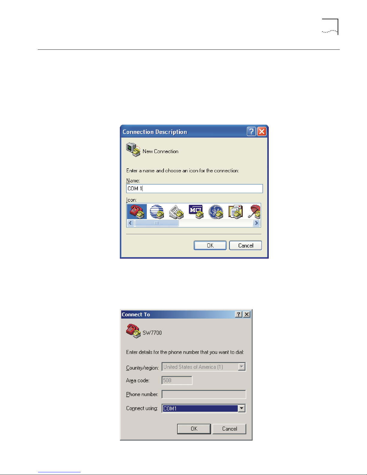
2 The HyperTerminal window displays the Connection Description dialog box, as
shown in
Figure 2 Set up the New Connection
Figure 2.
3 Enter the name of the new connection in the Name field and click OK. The dialog
box, shown in
Figure 3 displays.
4 Select the serial port to be used from the Connect using dropdown menu.
Figure 3 Properties Dialog Box
Page 14
6 CHAPTER 1: SYSTEM ACCESS
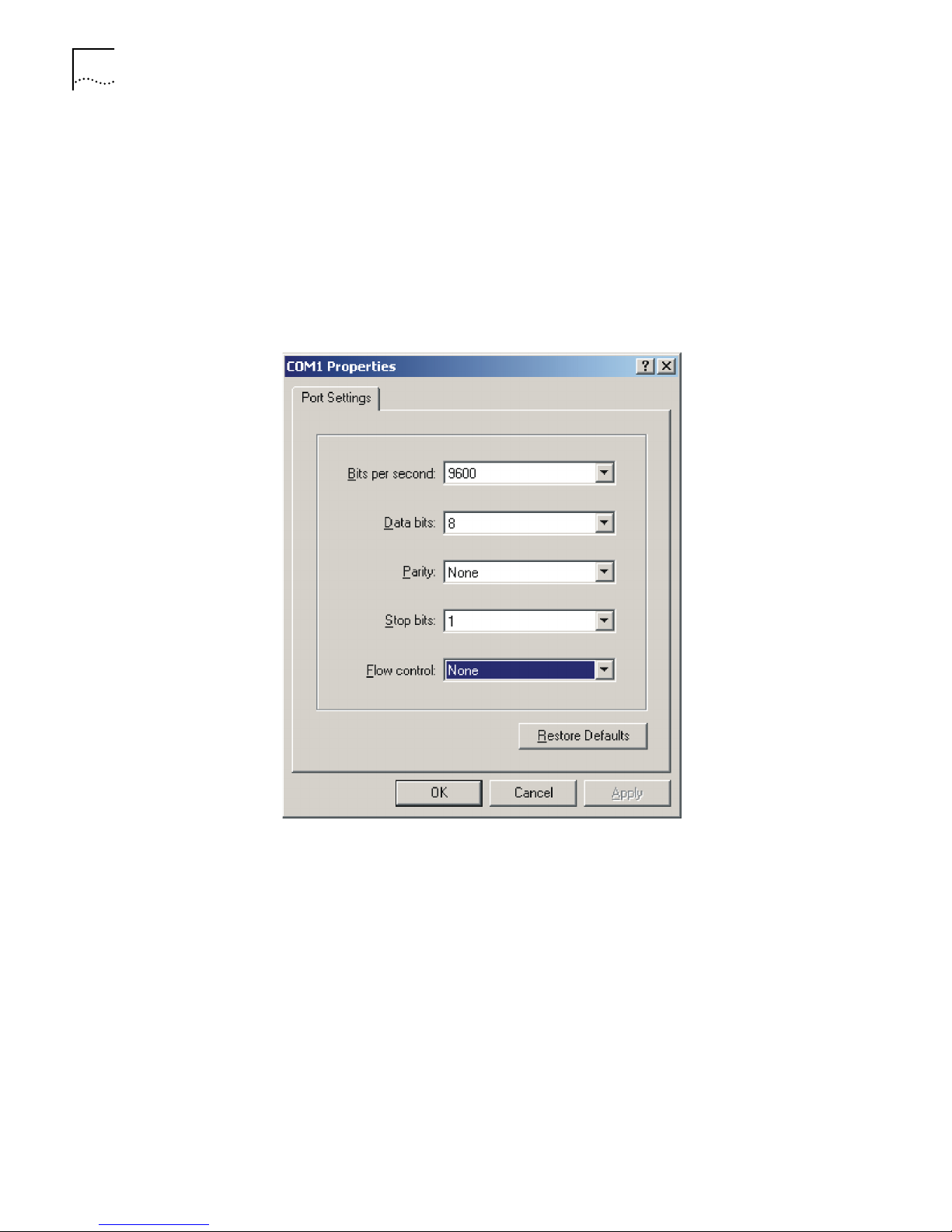
5 Click OK. The Port Settings tab, shown in Figure 4, displays and you can set serial
port parameters. Set the following parameters:
■ Baud rate = 9600
■ Databit = 8
■ Parity check = none
■ Stopbit = 1
■ Flow control = none
Figure 4 Set Communication Parameters
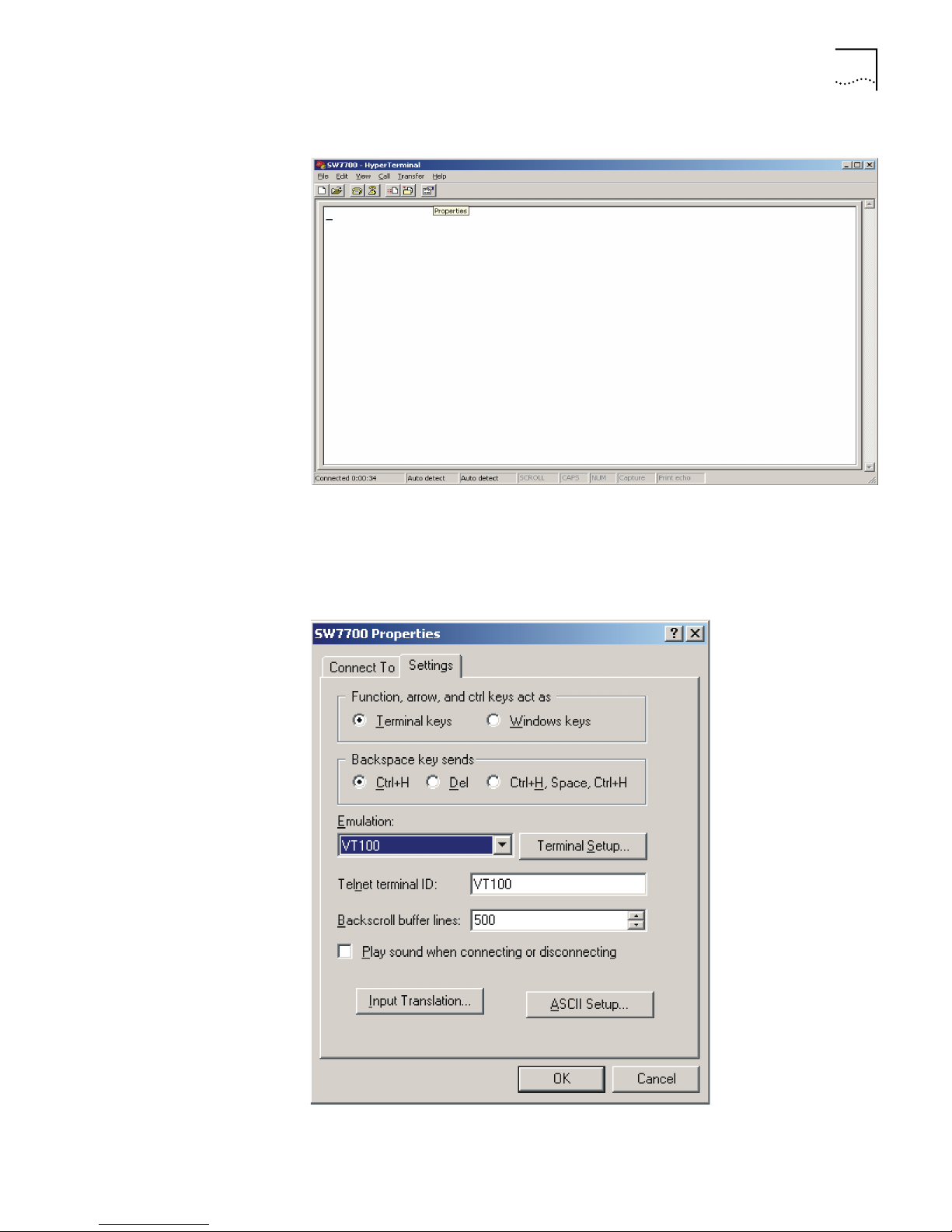
6 Click OK. The HyperTerminal dialogue box displays, as shown in Figure 5.
7 Select Properties.
Page 15
Setting Terminal Parameters 7
Figure 5 HyperTerminal Window
8 In the Properties dialog box, select the Settings tab, as shown in Figure 6.
9 Select VT100 in the Emulation dropdown menu.
10 Click OK.
Figure 6 Settings Tab
Page 16
8 CHAPTER 1: SYSTEM ACCESS
Configuring Through
Te ln e t
After you have correctly configured the IP address of a VLAN interface for an
Ethernet switch through the console port (using the ip address command in
VLAN interface view), and added the port (that connects to a terminal) to this
VLAN (using the port command in VLAN view), you can telnet this Switch 7700
and configure it.
Connecting the PC to the Switch 7700
To connect the PC and Switch 7700 through Telnet:
1 Authenticate the Telnet user through the console port before the user logs in by
Te ln e t.
Note: By default, the password is required for authenticating the Telnet user to
log in the Ethernet switch. If a user logs in by Telnet without a password, the user
sees the message:
Password required, but none set.
2 Enter system view, return to user view by pressing Ctrl+Z.
<SW7700> system-view
[SW7700] user-interface vty 0 4
[SW7700-ui-vty0] set authentication password simple/cipher xxxx
(xxxx is the preset login password of Telnet user)
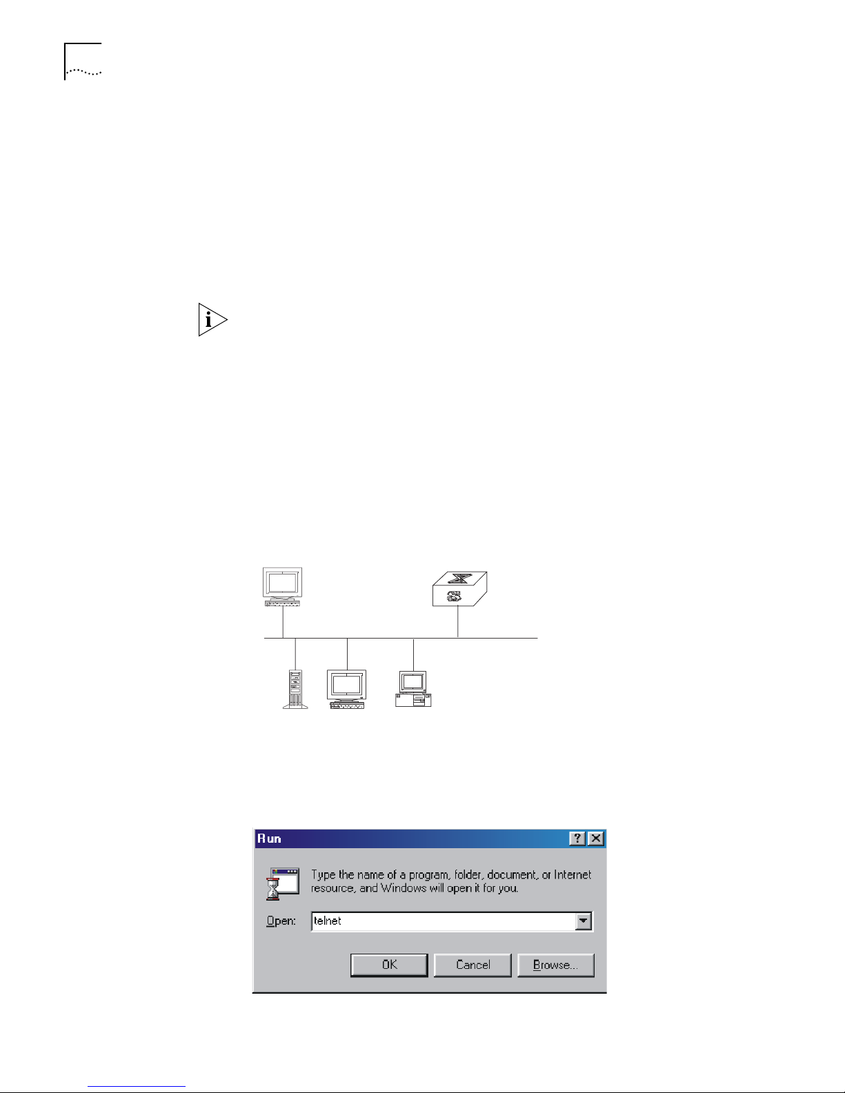
3 To set up the configuration environment, connect the Ethernet port of the PC to
that of the Ethernet switch through the LAN. See
Figure 7.
Figure 7 Setting up the Configuration Environment Through Telnet
Workstation
Ethernet port
WorkstationServer
PC (for configuring
the switch through Telnet)
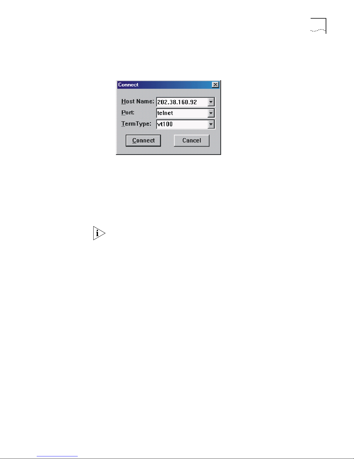
4 Run Telnet on the PC by selecting Start > Run from the Windows desktop and
entering Teln et in the Open field, as shown in
Figure 8 Run Telnet
Figure 8. Click OK.
Page 17
Setting Terminal Parameters 9
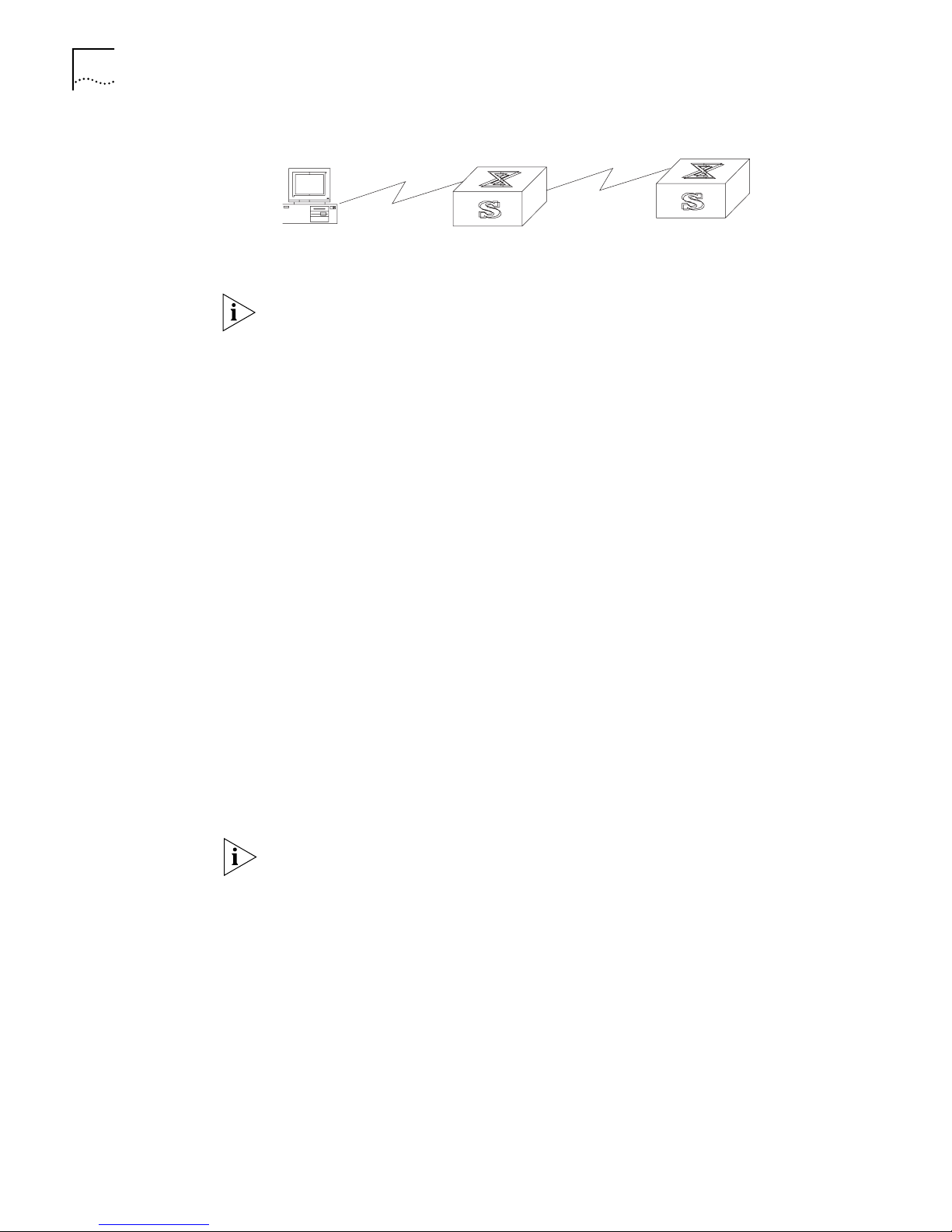
5 On the Connect dialog box, enter the IP address of the VLAN connected to the PC
port and set the terminal type to VT100, as shown in
Figure 9 Connect Ethernet Switch by Telnet
Figure 9.
The terminal displays User Access Verification and prompts you for the logon
password.
6 Enter the password,. The terminal displays the command line prompt (<SW7700>).
If the message, Too many users! appears, try to reconnect later. At most, 5
Telnet users are allowed to log on to the Switch 7700 Switch simultaneously.
7 Use the appropriate commands to configure the Ethernet switch or to monitor the
running state. Enter
? to get the immediate help. For details of specific commands,
refer to the chapters in this guide.
Note: When configuring the Ethernet switch via Telnet, do not modify the IP
address of it unless necessary, for the modification might terminate the Telnet
connection. By default, after logging on, a Telnet user can access the commands
at Level 0.
Connecting Two Switch 7700 Systems
After you have correctly configured IP address of a VLAN interface for an Ethernet
Switch through the console port (using the ip address command in VLAN
interface view), and have added the port (that connects to a terminal) to this VLAN
(using the port command in VLAN view), you can telnet the Switch 7700 to
another Switch 7700 to carry out the configuration, as shown in
Figure 10. The
local end is the Telnet client and the peer is the Telnet server. If the two switches
are located on the same LAN, their IP addressed should be configured on the same
segment or have a route between them.
After you telnet to an Ethernet switch, you can run the telnet command to log in
and configure another Ethernet switch.
Page 18
10 CHAPTER 1: SYSTEM ACCESS
Figure 10 Provide Telnet Client Service
PC
Telnet client
Telnet server
1 Authenticate the Telnet user through the console port on the Telnet Server
(Ethernet switch) before login.
Note: By default, the password is required for authenticating the Telnet user to
log in the Ethernet switch. If a user logs in via the Telnet without password, the
system displays the following message:
Password required, but none set.
2 Enter system view, return to user view by pressing Ctrl+Z.
<SW7700> system-view
[SW7700] user-interface vty 0
[SW7700-ui-vty0] set authentication password simple/cipher xxxx
(xxxx is the preset login password of Telnet user)
3 Log in to the Telnet client (Switch 7700). For the login process, see “Connecting
the PC to the Switch 7700”.
4 Perform the following operations on the Telnet client:
<SW7700> telnet xxxx
(xxxx can be the hostname or IP address of the Telnet Server. If it is the hostname,
the switch shall have the static resolution function.)
5 Enter the preset login password. The Switch 7700 prompt (<SW7700>) displays. If
the message,
Too many users! displays, try to connect later.
6 Use the appropriate commands to configure the Switch 7700 or view its running
state. Enter
? to get the immediate help. For details on a specific command, refer
to the appropriate chapter in this guide.
Configuring Through a
Dial-up the Modem
To configure your router through a dial-up modem:
1 Authenticate the modem user through the console port of the Switch 7700 before
the user logs in to the switch through a dial-up modem.
Note: By default, the password is required for authenticating the modem user to
log in to the Switch 7700. If a user logs in through the modem without a
password, the user sees the message,
Password required, but none set.
a Enter system view, return user view with Ctrl+Z.
<SW7700> system-view
[SW7700] user-interface aux 0
[SW7700-ui-aux0] set authentication password simple/cipher xxxx
(xxxx is the preset login password of the Modem user.)
b Using the modem command, you can configure the console port as in modem
mode.
[SW7700-ui-aux0] modem
2 To set up the remote configuration environment, connect the modems to a PC (or
a terminal) serial port and to the Switch 7700 console port, as shown in
Set Up
Remote Configuration Environment.
Page 19
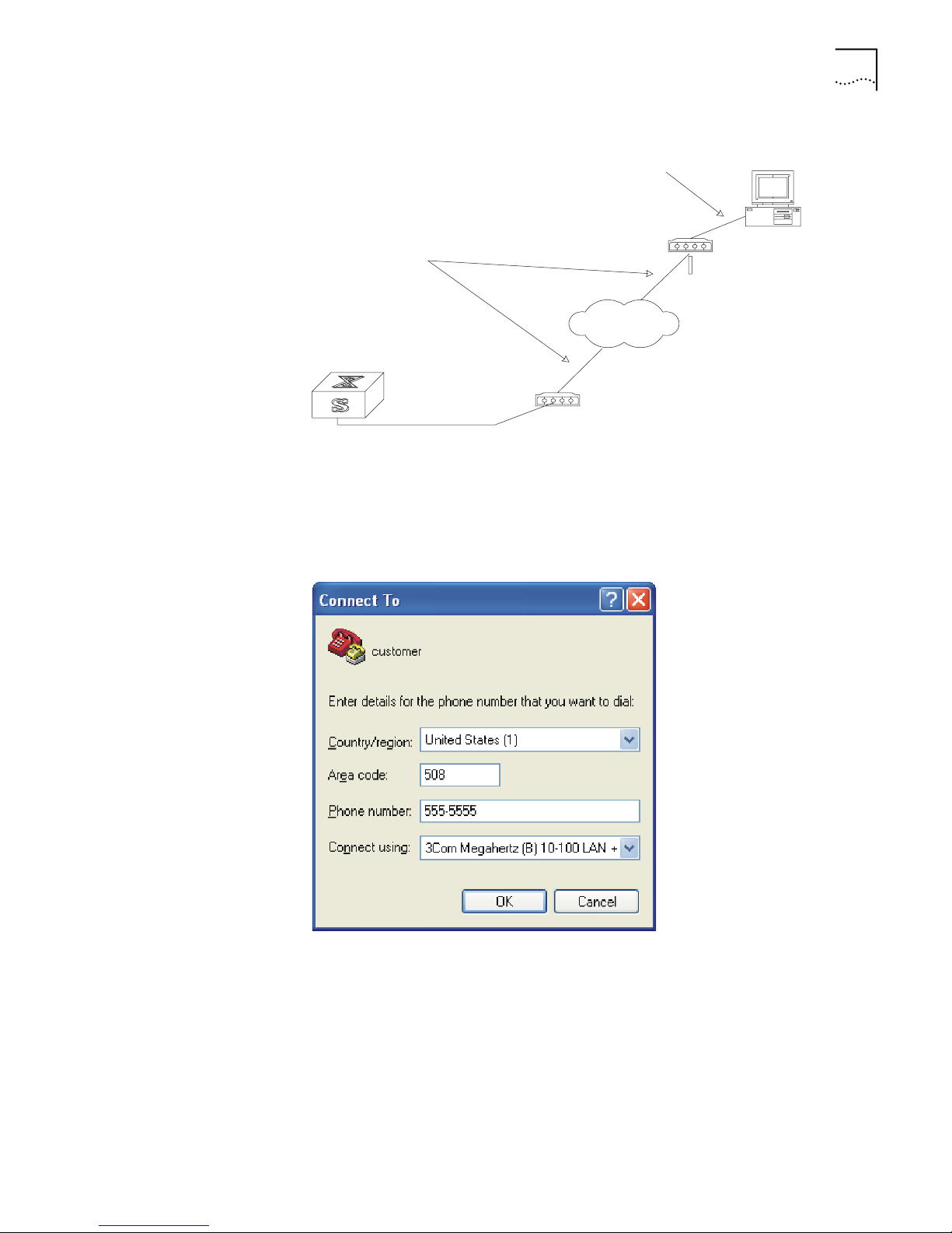
Figure 11 Set Up Remote Configuration Environment
Modem serial port line
Modem
Telephone line
PST
Modem
Setting Terminal Parameters 11
Console port
Remote telephone:
555-5555
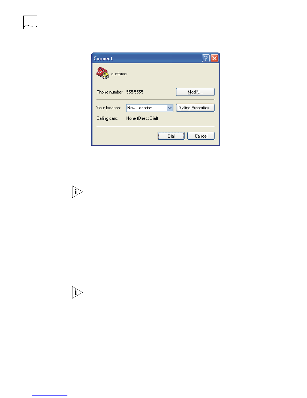
3 Dial for a connection to the switch, using the terminal emulator and modem on
the remote end. Dial the telephone number of the modem connected to the
Ethernet switch. See
Figure 12 Set the Dialed Number
Figure 12 and Figure 13.
Page 20
12 CHAPTER 1: SYSTEM ACCESS
4 Enter the preset login password on the remote terminal emulator and wait for the
5 Use the appropriate commands to configure the Switch 7700 or view its running
Figure 13 Dial the Remote PC
<SW7700> prompt.
state. Enter
? to get the immediate help. For details on a specific command, refer
to the appropriate chapter in this guide.
Configuring the User
Interface
Note: By default, after login, a modem user can access the commands at Level 0.
User interface configuration is another way to configure and manage port data.
The Switch 7700 supports the following configuration methods:
■ Local configuration through the console port
■ Remote configuration through Telnet on the Ethernet port
■ Remote configuration through a modem through the console port.
There are two types of user interfaces:
■ AUX user interface is used to log in the Ethernet switch through a dial-up
modem. A Switch 7700 can only have one AUX port.
■ VTY user interface is used to telnet the Ethernet switch.
Note: For the Switch 7700, the AUX port and Console port are the same port.
There is only the type of AUX user interface.
The user interface is numbered by absolute number or relative number.
To number the user interface by absolute number:
■ The AUX user interface is the first interface — user interface 0.
■ The VTY is numbered after the AUX user interface. The absolute number of the
first VTY is the AUX user interface number plus 1.
Page 21

Setting Terminal Parameters 13
To number the user interface by relative number, represented by interface +
number assigned to each type of user interface:
■ AUX user interface = AUX 0.
■ The first VTY interface = VTY 0, the second one = VTY 1, and so on.
To configure the user interface:
■ Enter the User Interface View
■ Configure the Attributes of the AUX (Console) Port
■ Configure the Terminal Attributes
■ Manage Users
■ Configure the Attributes of a Modem
■ Configure Redirection
Enter the User Interface View
Use the user-interface command (see Tab le 2) to enter a user interface view. You
can enter a single user interface view or multi-user interface view to configure one
or more user interfaces.
Perform the following configuration in system view.
Ta bl e 2 Enter User Interface View
Operation Command
Enter a single user interface view or
user-interface [ type ] first-number [ last-number ]
multi user interface views
Configure the Attributes of the AUX (Console) Port
Use the speed, flow control, parity, stop bit, and data bit commands (see
Ta bl e 3) to configure these attributes of the AUX (Console) port.
Perform the following configurations in user interface (AUX user interface only)
view.
Ta bl e 3 Configure the Attributes of the AUX (Console) Port
Operation Command
Configure the transmission
speed on AUX (Console) port.
By default, the transmission
speed is 9600bps
Restore the default
transmission speed on AUX
(Console) port
Configure the flow control on
AUX (Console) port. By
default, no flow control is
performed on the AUX
(Console) port
Restore the default flow
control mode on AUX
(Console) port
speed speed-value
undo speed
flow-control { hardware | none | software }
undo flow-control
Page 22

14 CHAPTER 1: SYSTEM ACCESS
Table 3 Configure the Attributes of the AUX (Console) Port
Operation Command
Configure parity mode on the
AUX (Console) port. By
default, there is no parity bit
on the AUX (Console) port
Restore the default parity
mode
Configure the stop bit of AUX
(Console) port. By default,
AUX (Console) port supports 1
stop bit
Restore the default stop bit of
AUX (Console) port
Configure the data bit of AUX
(Console) port. By default,
AUX (Console) port supports 8
data bits.
Restore the default data bit of
AUX (Console) port
parity { even | mark | none | odd | space }
undo parity
stopbits { 1 | 1.5 | 2 }
undo stopbits
databits { 7 | 8 }
undo databits
Configure the Terminal Attributes
The following commands can be used for configuring the terminal attributes,
including enabling/disabling terminal service, disconnection upon timeout,
lockable user interface, configuring terminal screen length and history command
buffer size.
Perform the following configuration in user interface view. Perform the lock
command in user view.
Enabling and Disabling Terminal Service After the terminal service is
disabled on a user interface, you cannot log in to the Switch 7700 through the
user interface. However, if a user logged in through the user interface before
disabling the terminal service, the user can continue operation. After the user logs
out, the user cannot log in again. In this case, the user can log in to the switch
through the user interface only when the terminal service is enabled again. Use
the commands described in
Ta bl e 4 Enable/Disable Terminal Service
Operation Command
Enable terminal service shell
Disable terminal service undo shell
Ta bl e 4 to enable or disable terminal service.
By default, terminal service is enabled on all the user interfaces.
Note the following points:
■ For the sake of security, the undo shell command can only be used on the user
interfaces other than the AUX user interface.
■ You cannot use this command on the user interface through which you log in.
■ You must confirm before using the undo shell command in any legal user
interface.
Page 23

Setting Terminal Parameters 15
Configure idle-timeout By default, idle-timeout is enabled and set to 10
minutes on all the user interfaces. The idle-timeout command is described in
Ta bl e 5.
Ta bl e 5 Idle Timeout
Operation Command
Configure idle-timeout idle-timeout minutes [ seconds ] (idle-timeout 0 means
Restore the default idle-timeout undo idle-timeout
disabling idle-timeout.)
Lock user interface This command locks the current user interface and
prompts the user to enter a password. This makes it impossible for others to
operate in the interface after the user leaves. The lock command is described in
Ta bl e 6.
Ta bl e 6 Lock User Interface
Operation Command
Lock user interface lock
Set the screen length If a command displays more than one screen of
information, you can use the screen length command to determine how many
lines are displayed on a screen so that information can be separated in different
screens and you can view it more conveniently. The screen-length command is
described in
Ta bl e 7 Setting Screen Length
Ta bl e 7.
Operation Command
Set the screen length screen-length screen-length (screen-length 0 indicates to
Restore the default screen
length
disable screen display separation function.)
undo screen-length
By default, the terminal screen length is 24 lines.
Set the History Command Buffer SIze Ta bl e 8 describes the
history-command max-size command. By default, the size of the history
command buffer is 10.
Ta bl e 8 Set the History Command Buffer Size
Operation Command
Set the history command
buffer size
Restore the default history
command buffer size
history-command max-size value
undo history-command max-size
Manage Users
The management of users includes the setting of the user logon authentication
method, the level of command a user can use after logging on, the level of
command a user can use after logging on from the specifically user interface, and
command level.
Page 24

16 CHAPTER 1: SYSTEM ACCESS
1 Configure local password authentication for the user interface.
Configure the Authentication Method The authentication-mode
command configures the user login authentication method that denies access to
an unauthorized user.
Ta bl e 9 describes the authentication-mode command.
Perform the following configuration in user interface view.
Ta bl e 9 Configure Authentication Method
Operation Command
Configure the authentication
method
Configure no authentication authentication-mode none
authentication-mode { password | scheme }
By default, terminal authentication is not required for users who log in through
the console port, whereas the password is required for authenticating the modem
and Telnet users when they log in.
To configure authentication for modem and Telnet users:
When you set the password authentication mode, you must also configure a login
password to log in successfully.
Ta bl e 10 describes the set authentication
password command.
Perform the following configuration in user interface view.
Ta bl e 10 Configure the Local Authentication Password
Operation Command
Configure the local authentication
password
Remove the local authentication
password
set authentication password { cipher | simple }
password
undo set authentication password
Configure for password authentication when a user logs in through a VTY 0 user
interface and set the password to 3Com:
[SW7700] user-interface vty 0
[SW7700-ui-vty0] authentication-mode password
[SW7700-ui-vty0] set authentication password simple 3Com
2 Configure the local or remote authentication username and password.
Use the authentication-mode scheme command to perform local or remote
authentication of username and password. The type of the authentication
depends on your configuration. For detailed information, see “AAA and Radius”
Perform username and password authentication when a user logs in through the
VTY 0 user interface and set the username and password to zbr and 3Com
respectively:
[SW7700-ui-vty0] authentication-mode scheme
[SW7700-ui-vty0] quit
[SW7700] local-user zbr
[SW7700-user-zbr] password simple 3Com
3 Do not configure authentication
[SW7700-ui-vty0] authentication-mode none
Page 25

Setting Terminal Parameters 17
Note: By default, the password is required for authenticating the modem and
Telnet users when they log in. If the password has not been set, when a user logs
in, the following message displays,
Password required, but none set.
If the authentication-mode none command is used, the modem and Telnet
users are not required to enter a password.
Set the Command Level after Login The following command is used for
setting the command level used after a user logs in.
Perform the following configuration in local-user view.
Ta bl e 11 Set Command Level Used After a User Logs in
Operation Command
Set command level used after
a user logging in
Restore the default command
level used after a user logging
in
service-type telnet level level
undo service-type telnet level
Set the Command Level Used after a User Logs in from a User Interface
Use the user privilege level command to set the command level after a user logs
in from a specific user interface so that a user is able to execute the commands at
that command level.
Ta bl e 12 describes the user privilege level command.
Perform the following configuration in user interface view.
Ta bl e 12 Set Command Level after User Login
Operation Command
Set command level used after
a user logging in from a user
interface
Restore the default command
level used after a user logging
in from a user interface
user privilege level level
undo user privilege level
By default, a user can access the commands at Level 3 after logging in through the
AUX user interface, and the commands at Level 0 after logging in through the VTY
user interface.
When a user logs in to the switch, the command level that the user can access
depends on two points. One is the command level that the user itself can access,
the other is the set command level of this user interface. If the two levels are
different, the former is taken. For example, the command level of VTY 0 user
interface is 1, however, user Tom has the right to access commands of level 3; if
Tom logs in from VTY 0 user interface, he can access commands of level 3 and
lower.
Set Command Priority The command-privilege level command sets the
priority of a specified command in a certain view. The command levels include
visit, monitoring, configuration, and management, which are identified with
command level 0 through 3, respectively. An administrator assigns authority
according to user requirements. See
Ta bl e 13.
Page 26

18 CHAPTER 1: SYSTEM ACCESS
Perform the following configuration in system view.
Ta bl e 13 Set Command Priority
Operation Command
Set the command priority in a
specified view.
Restore the default command
level in a specified view.
command-privilege level level view view command
undo command-privilege view view command
Configure the Attributes of a Modem
You can use the commands described in Ta b le 14 to configure the attributes of a
modem when logging in to the switch through the modem.
Perform the following configuration in user interface view.
Ta bl e 14 Configure Modem
Operation Command
Set the interval since the system
receives the RING until CD_UP
Restore the default interval since
the system receives the RING until
CD_UP
Configure auto answer modem auto-answer
Configure manual answer undo modem auto-answer
Configure to allow call-in modem call-in
Configure to bar call-in undo modem call-in
Configure to permit call-in and
call-out.
Configure to disable call-in and
call-out
modem timer answer seconds
undo modem timer answer
modem both
undo modem both
Configure Redirection
The send command can be used for sending messages between user
interfaces. See
Perform the following configuration in user view.
Ta bl e 15 Configure to Send Messages Between User Interfaces
Operation Command
Configure to send messages
between different user interfaces.
The auto-execute command is used to run a command automatically after
you log in. The command is automatically executed when you log in again. See
Ta bl e 16.
This command is usually used to execute the telnet command automatically on
the terminal, which connects the user to a designated device.
Ta bl e 15.
send { all | number | type number }
Page 27

Command Line Interface 19
Perform the following configuration in user interface view.
Ta bl e 16 Configure Automatic Command Execution
Operation Command
Configure to automatically run the
command
Configure not to automatically run
the command
auto-execute command text
undo auto-execute command
Note the following points:
■ After executing the auto-execute command, the user interface can no longer
be used to carry out the routine configurations for the local system. Use this
command with caution.
■ Make sure that you will be able to log in to the system in some other way and
cancel the configuration, before you use the auto-execute command and
save the configuration.
Telnet 10.110.100.1 after the user logs in through VTY0 automatically.:
[SW7700-ui-vty0] auto-execute command telnet 10.110.100.1
Command Line
Interface
When a user logs on via VTY 0, the system will run telnet 10.110.100.1
automatically.
Display and Debug User Interface
After creating the previous configuration, execute the display command in all
views to display the user interface configuration, and to verify the effect of the
configuration. Execute the free command in user view to clear a specified user
interface.
Ta bl e 17 Display and Debug User Interface
Operation Command
Clear a specified user interface free user-interface [ type ] number
Display the user application
information of the user
interface
Display the physical attributes
and some configurations of
the user interface
See Ta bl e 17.
display users [ all ]
display user-interface [ type number ] [ number ]
The Switch 7700 provides a series of configuration commands and command line
interfaces for configuring and managing the Switch 7700. The command line
interface has the following features.
■ Local configuration through the console port.
■ Local or remote configuration through Telnet.
■ Remote configuration through a dial-up Modem to log in to the Switch 7700.
■ Hierarchy command protection to prevent unauthorized users from accessing
■ Access to online Help by entering ?.
the switch.
Page 28

20 CHAPTER 1: SYSTEM ACCESS
■ Network test commands, such as Tracert and Ping, for rapid troubleshooting of
the network.
■ Detailed debugging information to help with network troubleshooting.
■ Ability to log in and manage other Ethernet switches directly, using the telnet
command.
■ FTP service for the users to upload and download files.
■ A function similar to Doskey to execute a history command.
■ The command line interpreter that searches for a target not fully matching the
keywords. You can enter the whole keyword or part of it, as long as it is unique
and not ambiguous.
Command Line View The Switch 7700 provides hierarchy protection for the command lines to prevent
unauthorized users from accessing the switch illegally.
There are four levels of commands:
■ Visit level — involves commands for network diagnosis tools (such as ping and
tracert), command of the switch between different language environments of
user interface (language-mode) and the telnet command. Saving the
configuration file is not allowed on this level of commands.
■ Monitoring level — includes the display command and the debugging
command for system maintenance, service fault diagnosis, and so on. Saving
the configuration file is not allowed on this level of commands.
■ Configuration level — provides service configuration commands, such as the
routing command and commands on each network layer that are used to
provide direct network service to the user.
■ Management level — influences the basic operation of the system and the
system support module which plays a support role for service. Commands at
this level involve file system commands, FTP commands, TFTP commands,
XModem downloading commands, user management commands, and level
setting commands.
Login users are also classified into four levels that correspond to the four
command levels. After users of different levels log in, they can only use commands
at their own, or lower, levels.
To prevent unauthorized users from illegal intrusion, users are identified when
switching from a lower level to a higher level with the super [ level ] command.
User ID authentication is performed when users at a lower level switch to users at
a higher level. Only when correct password is entered three times, can the user
switch to the higher level. Otherwise, the original user level remains unchanged.
Command views are implemented according to requirements that are related to
one another. For example, after logging in to the Ethernet switch, you enter user
view, in which you can only use some basic functions,such as displaying the
running state and statistics information. In user view, key in system-view to enter
system view, in which you can key in different configuration commands and enter
the corresponding views.
Page 29

The command line provides the following views:
■ User view
■ System view
■ Ethernet Port view
■ VLAN view
■ VLAN interface view
■ Local-user view
■ User interface view
■ FTP client view
■ Cluster view
■ PIM view
■ RIP view
■ OSPF view
■ OSPF area view
■ Route policy view
Command Line Interface 21
■ Basic ACL view
■ Advanced ACL view
■ Interface-based ACL view
■ Layer-2 ACL view
■ RADIUS server group view
■ ISP domain view
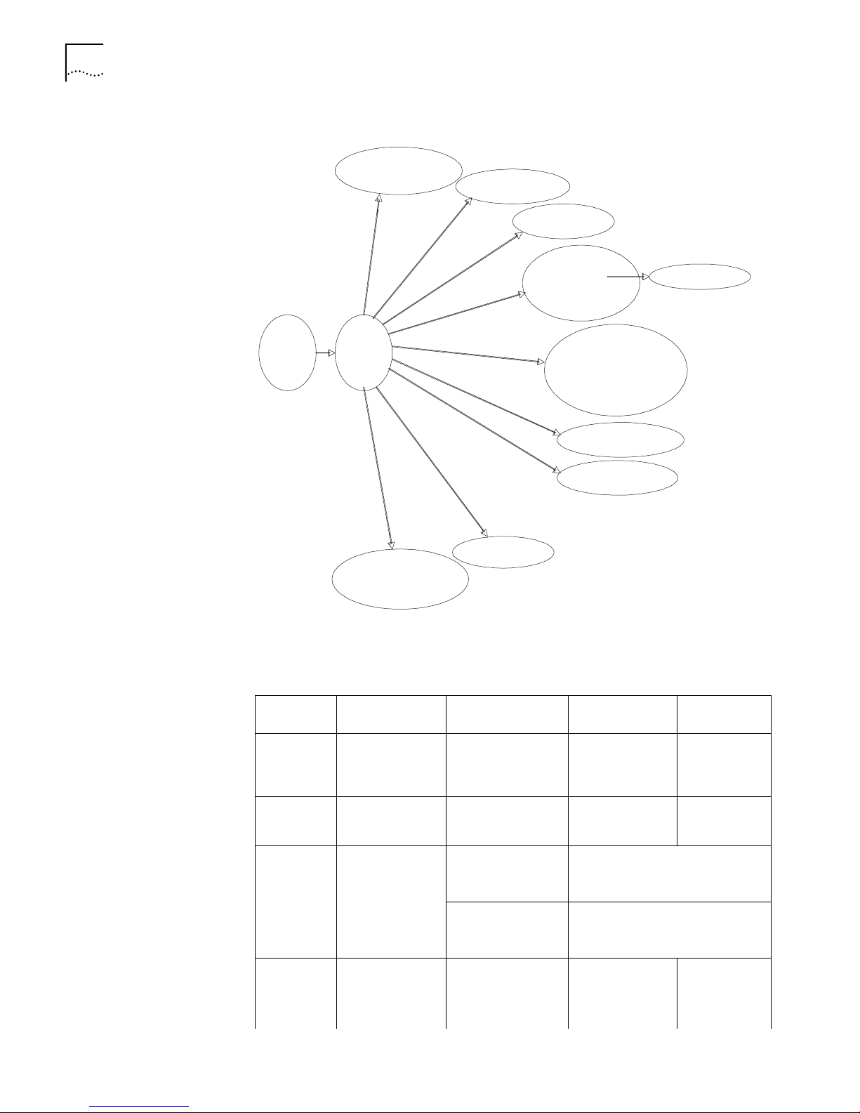
The relation diagram of the views is shown in Figure 14.
Page 30
22 CHAPTER 1: SYSTEM ACCESS
Ethernet port view
User interface viiew
VLAN view
VLAN interface view
User view
System
view
RIP view
OSPF view
Route policy view
OSPF area view
Basic ACL view
Advanced ACL view
Interface-based ACL view
Layer-2 ACL view
FTP client view
Local-user view
PIM view
RADIUS server group view
Figure 14 Relation Diagram of the Views
The Tab le 18 describes the function features of different views and the commands
to enter or quit.
Ta bl e 18 Function Feature of Command View
Command
view
User view Show the basic
System view Configure system
Ethernet Port
view
VLAN view Configure VLAN
Function Prompt
information about
operation and
statistics
parameters
Configure
Ethernet port
parameters
parameters
Command to
enter
<SW7700> Enter right after
connecting the
switch
[SW7700] Key in
system-view in
user view
[SW7700-Ether
net1/0/1]
100M Ethernet port view
Key in interface ethernet 1/0/1 in
system view
[SW7700-Gigabit
Ethernet1/0/1]
GigabitEthernet port view
Key in interface gigabitethernet
1/0/1
in system view
[SW7700-Vlan1] Key in vlan 1 in
System view
Command to
exit
quit
disconnects to
the switch.
quit or return
returns to user
view
quit returns to
System view
return returns
to user view
Page 31

Table 18 Function Feature of Command View
Command Line Interface 23
Command
view
VLAN
interface
view
Function Prompt
Configure IP
interface
parameters for a
VLAN or a VLAN
aggregation
Local-user
view
User
interface
view
FTP Client
view
Configure local
user parameters
Configure user
interface
parameters
Configure FTP
Client parameters
PIM view Configure PIM
parameters
RIP view Configure RIP
parameters
OSPF view Configure OSPF
parameters
OSPF area
view
Route policy
view
Basic ACL
view
Advanced
ACL view
Interface-bas
ed ACL view
Configure OSPF
area parameters
Configure route
policy parameters
Define the rule of
basic ACL
Define the rule of
advanced ACL
Define the rule of
interface-based
ACL
Command to
enter
[SW7700-Vlaninterface1]
Key in interface
vlan-interface 1
in System view
[SW7700-useruser1]
Key in local-user
user1 in System
view
[SW7700-ui0] Key in
user-interface 0
in System view
[ftp] Key in ftp in user
view
[SW7700-PIM] Key in pim in
System view
[SW7700-rip] Key in rip in
System view
[SW7700-ospf] Key in ospf in
System view
[SW7700-ospf-0.
0.0.1]
[SW7700-routepolicy]
Key in area 1 in
OSPF view
Key in
route-policy
policy1 permit
node 10 in
System view
[SW7700-aclbasic-1]
Key in acl
number 1 in
System view
[SW7700-acl-adv
-100]
Key in acl
number 100 in
System view
[SW7700-acl-if1000]
Key in acl
number 1000 in
System view
Command to
exit
quit returns to
System view
return returns
to user view
quit returns to
System view
return returns
to user view
quit returns to
System view
return returns
to user view
quit returns to
System view
return returns
to user view
quit returns to
hgmp view
return returns
to user view
quit returns to
System view
return returns
to user view
quit returns to
System view
return returns
to user view
quit returns to
System view
return returns
to user view
quit returns to
System view
return returns
to user view
quit returns to
System view
return returns
to user view
quit returns to
System view
return returns
to user view
quit returns to
System view
return returns
to user view
Page 32

24 CHAPTER 1: SYSTEM ACCESS
Table 18 Function Feature of Command View
Feature and Functions of
the Command Line
Command
view
Layer-2 ACL
view
RADIUS
server group
view
ISP domain
view
Function Prompt
Define the rule of
layer-2 ACL
Configure radius
parameters
Configure ISP
domain
parameters
[SW7700-acllink-200]
[SW7700-radius-1]Key in radius
[SW7700-isp-163
.net]
Command to
enter
Key in acl
number 200 in
System view
scheme 1 in
System view
Key in domain
isp-163.net in
System view
Command to
exit
quit returns to
System view
return returns
to user view
quit returns to
System view
return returns
to user view
quit returns to
System view
return returns
to user view
Online Help
The command line interface provides full and partial online Help modes.
You can get the help information through these online help commands, which are
described as follows.
■ Enter ? in any view to get all the commands in it and corresponding
descriptions.
<SW7700> ?
User view commands:
language-mode Specify the language environment
ping Ping function
quit Exit from current command view
super Enter the command workspace with specified user priority
level
telnetEstablish one TELNET connection
tracertTrace route function
■ Enter a command with a ?, separated by a space. If this position is for
keywords, then all the keywords and the corresponding brief descriptions will
be listed.
<SW7700> ping ?
-a Select source IP address
-c Specify the number of echo requests to send
-d Specify the SO_DEBUG option on the socket being used
-h Specify TTL value for echo requests to be sent
-I Select the interface sending packets
-n Numeric output only. No attempt will be made to lookup host
addresses for symbolic names
-p No more than 8 "pad" hexadecimal characters to fill out the sent
packet. For example, -p f2 will fill the sent packet with f and 2
repeatedly
-q Quiet output. Nothing is displayed except the summary lines at
startup time and when finished
-r Record route. Includes the RECORD_ROUTE option in the ECHO_REQUEST
packet and displays the route
-s Specifies the number of data bytes to be sent
-t Timeout in milliseconds to wait for each reply
Page 33

Command Line Interface 25
-v Verbose output. ICMP packets other than ECHO_RESPONSE that are
received are listed
STRING<1-20> IP address or hostname of a remote system
Ip IP Protocol
■ Enter a command with a ?, separated by a space. If this position is for
parameters, all the parameters and their brief descriptions will be listed.
[SW7700] garp timer leaveall ?
INTEGER<65-32765> Value of timer in centiseconds
(LeaveAllTime > (LeaveTime [On all ports]))
Time must be multiple of 5 centiseconds
[SW7700] garp timer leaveall 300 ?
<cr>
<cr> indicates no parameter in this position. The next command line repeats
the command, you can press Enter to execute it directly.
■ Enter a character string with a ?, and list all the commands beginning with this
character string.
<SW7700>p?
ping
■ Input a command with a character string and ?, and list all the key words
beginning with this character string in the command.
<SW7700> display ver?
version
Common Command Line Error Messages
All the commands that are entered by users can be correctly executed if they have
passed the grammar check. Otherwise, error messages are reported to users. The
common error messages are listed in
Ta bl e 19 Common Command Line Error Messages
Error messages Causes
Unrecognized command Cannot find the command.
Cannot find the keyword.
Wrong parameter type.
The value of the parameter exceeds the range.
Incomplete command The command is incomplete.
Too many parameters You entered too many parameters.
Ambiguous command The parameters you entered are not specificf.
Ta bl e 19.
History Command
The command line interface provides a function similar to DosKey. The commands
entered by users can be automatically saved by the command line interface and
you can invoke and execute them at any time. By default, he history command
buffer can store 10 history commands for each user. The operations are shown in
Ta bl e 20.
Ta bl e 20 Retrieve History Command
Operation Key
Display history
command
Result
display history-command Displays history commands by the
user who is entering them.
Page 34

26 CHAPTER 1: SYSTEM ACCESS
Table 20 Retrieve History Command
Operation Key
Retrieve the previous
history command
Retrieve the next history
command
Up cursor key <> or <Ctrl+P> Retrieves the previous history
Down cursor key <> or
<Ctrl+N>
command, if there is any.
Retrieves the next history
command, if there is any.
Result
Note: Cursor keys can be used to retrieve the history commands in Windows 3.X
Terminal and Telnet. However, in Windows 9X HyperTerminal, the cursor keys and
do not work, because Windows 9X HyperTerminal defines the two keys differently.
In this case, use the combination keys <Ctrl+P> and <Ctrl+N> instead for the same
purpose.
Editing Features of the Command Line
The command line interface provides a basic command editing function and
supports editing multiple lines. A command cannot be longer than 256 characters.
Ta bl e 21.
See
Ta bl e 21 Editing Functions
Key Function
Common keys Inserts at the cursor position and the cursor moves to the
right, if the edition buffer still has free space.
Backspace Deletes the character preceding the cursor and the cursor
Leftwards cursor key <> or Ctrl+B Moves the cursor a character backward
Rightwards cursor key <> or Ctrl+F Moves the cursor a character forward
Up cursor key <> or Ctrl+P
Down cursor key <> or Ctrl+N
Tab Press Tab after typing the incomplete key word and the
moves backward.
Retrieves the history command.
system will execute the partial help: If the key word
matching the typed one is unique, the system will replace
the typed one with the complete key word and display it
in a new line. If there is not a matched key word or the
matched key word is not unique, the system will do no
modification but displays the originally typed word in a
new line.
Displaying Features of the Command Line
If information to be displayed exceeds one screen, the pause function allows users
three choices, as descrbed in
Ta bl e 22 Display Functions
Key or Command Function
Press Ctrl+C when the display
pauses
Enter a space when the display
pauses
Press Enter when the display pauses Continue to display the next line of information.
Ta bl e 22.
Stop displaying and executing command.
Continue to display the next screen of information.
Page 35

2
PORT CONFIGURATION
This chapter covers the following topics:
■ Ethernet Port Overview
■ Link Aggregation Configuration
Ethernet Port
Overview
A brief description of Switch 7700 I/O modules are listed below:
■ 48-port 10/100Base-T auto-sensing fast Ethernet card
■ 8-port 1000Base-X (Gigabit Interface Converter or GBIC) Gigabit Ethernet card
■ 8-port 10/100/1000Base-T Gigabit Ethernet card
■ 24-port 100Base-FX MMF fast Ethernet card
The Ethernet ports of the Switch 7700 have the following features:
■ 10/100Base-T Ethernet ports support MDI/MDI-X auto-sensing, and can be
configured to operate in half/full duplex mode or auto-negotiation mode to
negotiate the duplex mode and speed with other network devices. This also
allows you to select the optimal mode automatically.
■ 100BaseFX MMF Ethernet ports operate in 100M full duplex mode. The duplex
mode can be configured as full (full duplex) or auto (auto-negotiation). The
speed can be set to 100 (100Mbps) or auto (auto-negotiation).
■ 1000BaseX Ethernet ports work in gigabit full duplex mode. The duplex mode
can be configured as full (full duplex) or auto (auto-negotiation). The speed can
be set to 1000 (1000Mbps) or auto (auto-negotiation).
■ 10/100/1000Base-T Ethernet ports support MDI/MDI-X auto-sensing, and the
modes are 1000 full duplex, 100M half/full duplex, and 10M half/full duplex.
Ethernet Port
Configuration
Ethernet port configuration includes:
■ Entering Ethernet Port View
■ Enabling and Disabling Ethernet PortS
■ Setting Description Character String for Ethernet Port
■ Setting Duplex Attribute of the Ethernet Port
■ Setting Speed of Ethernet Port
■ Setting Cable Type for Ethernet Port
■ Setting Flow Control for Ethernet Port
■ Permitting/Forbidding Jumbo Frames on the Ethernet port
■ Setting the Maximum MAC Addresses an Ethernet Port can Learn
Page 36
28 CHAPTER 2: PORT CONFIGURATION
■ Setting Link Type for Ethernet Port
■ Adding the Ethernet Port to a VLAN
■ Setting the Default VLAN ID for Ethernet Port
Entering Ethernet Port View
Before configuring the Ethernet port, enter Ethernet port view first.
Perform the following configuration in system view.
Ta bl e 1 Enter Ethernet Port View
Operation Command
Enter Ethernet port view interface {Gigabit | Ethernet} slot/subslot/port
Note: In the Switch 7700, the subslot is always 0.
Enabling and Disabling Ethernet PortS
The following command can be used for disabling or enabling the port. After
configuring the related parameters and protocol of the port, you can use the
following command to enable the port.
Perform the following configuration in Ethernet port view.
Ta bl e 2 Enable/Disable an Ethernet Port
Operation Command
Disable an Ethernet port shutdown
Enable an Ethernet port undo shutdown
Note: The port is enabled by default
Setting Description Character String for Ethernet Port
You can use the following command to identify the Ethernet ports.
Perform the following configuration in Ethernet port view.
Ta bl e 3 Set Description Character String for Ethernet Port
Operation Command
Set description character string for
Ethernet port.
Delete the description character
string of Ethernet.
description text
undo description
Note: The port description is a null character string by default.
Setting Duplex Attribute of the Ethernet Port
Set the port to full duplex to send and receive data packets at the same time. Set
the port to half-duplex to either send or receive only. If the port has been set to
auto-negotiation mode, the local and peer ports will automatically negotiate the
duplex mode.
Page 37
Ethernet Port Overview 29
Perform the following configuration in Ethernet port view.
Ta bl e 4 Set Duplex Attribute for Ethernet Port
Operation Command
Set duplex attribute for
Ethernet port.
Restore the default duplex
attribute of Ethernet port.
duplex {auto | full | half}
undo duplex
Note: 100M electrical Ethernet port can operate in full-duplex, half-duplex or
auto-negotiation mode. The Gigabit electrical Ethernet port can operate in full
duplex, half duplex or auto-negotiation mode. When the port operates at
1000Mbps, the duplex mode can be set to full (full duplex) or auto
(auto-negotiation).The optical 100M/Gigabit Ethernet ports support full duplex
mode and can be configured to operate in full (full duplex) or auto
(auto-negotiation) mode. The port is in auto (auto-negotiation) mode by default.
Setting Speed of Ethernet Port
You can use the following command to set the speed on the Ethernet port. If the
speed is set to auto (auto-negotiation) mode, the local and peer ports will
automatically negotiate the port speed.
Perform the following configuration in Ethernet port view.
Ta bl e 5 Set Speed on Ethernet Port
Operation Command
Set 100M Ethernet port speed speed {10 | 100 | auto}
Set Gigabit Ethernet port
speed
Restore the default speed on
Ethernet port
speed {10 | 100 | 1000 | auto}
undo speed
Note: 100M electrical Ethernet port can operate at 10Mbps and 100Mbps as per
different requirements. The electrical Gigabit Ethernet port can operate at
10Mbps, 100Mbps, or 1000Mbps as per different requirements. However in half
duplex mode, the port cannot operate at 1000Mbps.100M optical Ethernet port
supports 100Mbps and can be configured to operate at 100 (100Mbps) or auto
(auto-negotiation).The Gigabit Ethernet port supports1000Mbps and can be
configured to operate at 1000 (1000Mbps) and auto (auto-negotiation). The
speed of the port is auto mode by default.
Setting Cable Type for Ethernet Port
The Ethernet port supports the straight-through (MDI) and cross-over (MDIX)
network cables. The following command can be used for configuring the cable
type.
Perform the following configuration in Ethernet port view.
Ta bl e 6 Set the Type of the Cable Connected to the Ethernet Port
Operation Command
Set the type of the cable connected
to the Ethernet port.
mdi {across | auto | normal}
Page 38
30 CHAPTER 2: PORT CONFIGURATION
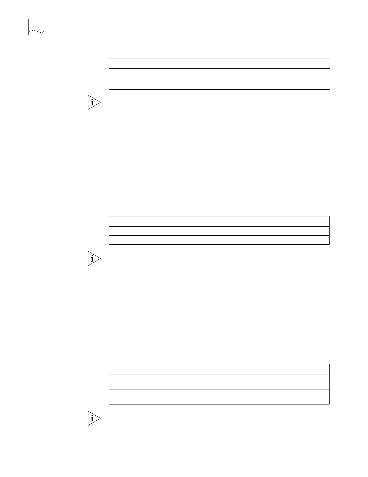
Table 6 Set the Type of the Cable Connected to the Ethernet Port
Operation Command
Restore the default type of the
cable connected to the Ethernet
port.
Note: The settings only take effect on 10/100Base-T and 10/100/1000Base-T
ports. The Switch 7700 only supports auto (auto-sensing). If you set some other
type, you will see the prompt “Not support this operation!”. The cable type is auto
(auto-recognized) by default. The system will automatically recognize the type of
cable connecting to the port.
Setting Flow Control for Ethernet Port
If congestion occurs in the local switch after enabling flow control in both the local
and the peer switch, then the switch will inform its peer to pause sending packets.
Once the peer switch receives this message, it will pause packet sending, and vice
versa. In this way, packet loss is effectively reduced. The flow control function of
the Ethernet port can be enabled or disabled through the following command.
Perform the following configuration in Ethernet port view.
undo mdi
Ta bl e 7 Set Flow Control for Ethernet Port
Operation Command
Enable Ethernet port flow control flow-control
Disable Ethernet port flow control undo flow-control
Note: Ethernet port flow control is disabled by default.
Permitting/Forbidding Jumbo Frames on the Ethernet port
Using the jumbo frame enable command, you can allow jumbo frames up to
9KB to pass through the specified Ethernet port. Note that packets up to 1536
bytes, including the IEEE 802.1Q tagging are always allowed to pass through
Ethernet ports.
Jumbo frames are only allowed for Ethernet Type II frames. Most network
equipment, including NICs, switches, and routers are not capable of supporting
jumbo frames and will always discard these packets.
Perform the following configuration in Ethernet port view.
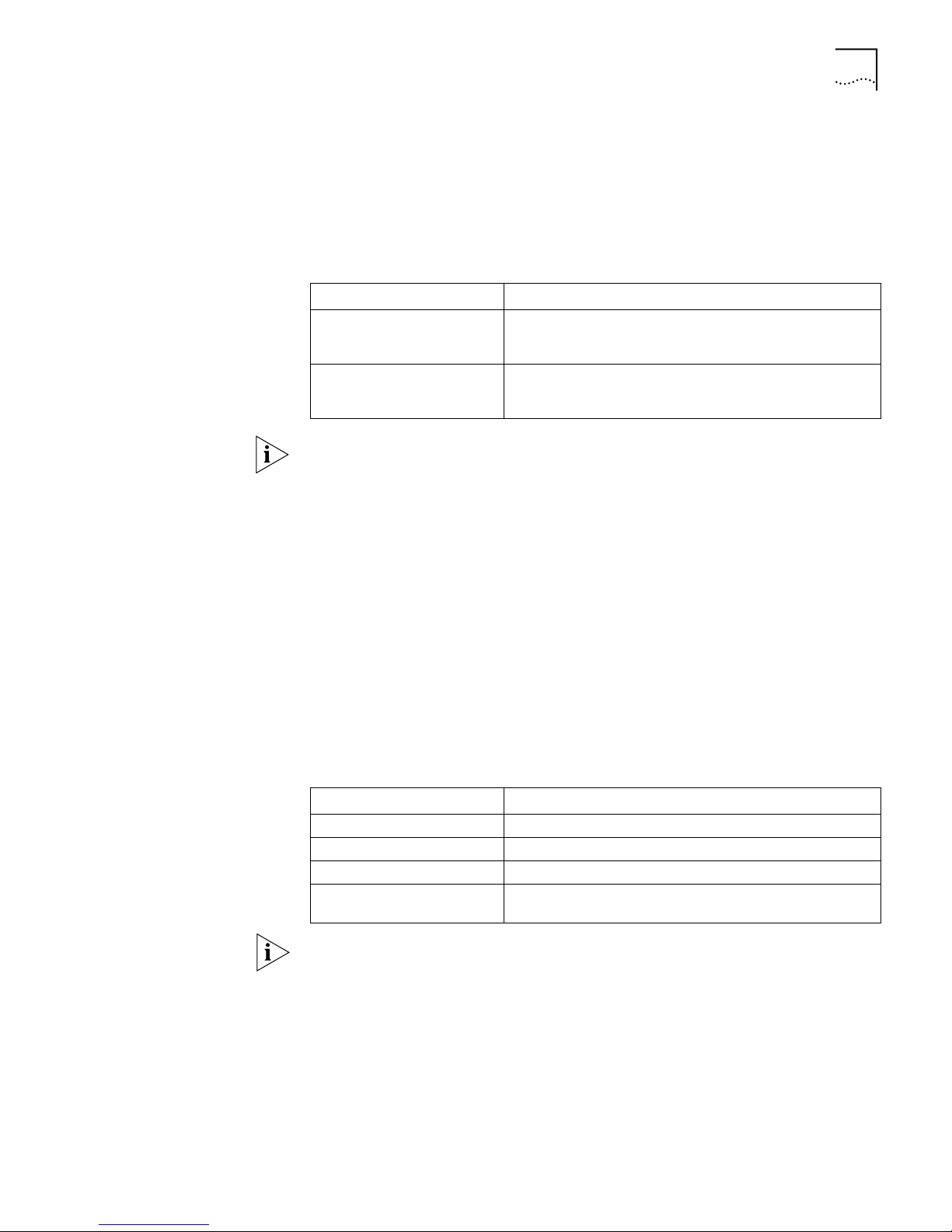
Ta bl e 8 Permitting/Forbidding Jumbo Frame to Pass Through the Ethernet Port
Operation Command
Permit jumbo frame to pass
through the Ethernet port.
Forbid jumbo frame to pass
through the Ethernet port.
jumboframe enable
undo jumboframe enable
Note: Jumbo frames are disabled by default.
Page 39
Ethernet Port Overview 31
Setting the Maximum MAC Addresses an Ethernet Port can Learn
Use the following command to set an amount limit on MAC addresses learned by
the Ethernet port. If the number of MAC address learned by this port exceeds the
value set by the user, this port will not learn MAC address.
Perform the following configuration in Ethernet port view.
Ta bl e 9 Set an Amount Limit to the MAC Addresses Learned by the Ethernet Port
Operation Command
Set an amount limit to the
MAC addresses learned by the
Ethernet port
Restore the default limit to the
MAC addresses learned by the
Ethernet port
mac-address max-mac-count count
undo mac-address max-mac-count
Note: If the count parameter takes 0, the port is no permitted to learn MAC
address. There is no limit to the amount of the MAC addresses that an Ethernet
port can learn by default. However how many MAC addresses a port can learn is
still restricted by MAC address table.
Setting Link Type for Ethernet Port
Ethernet port can operate in three different link types; access, hybrid, and trunk
types. The access port carries one VLAN only, used for connecting to the user’s
computer. The trunk port can belong to more than one VLAN and receive/send the
packets on multiple VLANs. The hybrid port can also carry more than one VLAN
and receive/send the packets on multiple VLANs. The difference between the
hybrid port and the trunk port is that the hybrid port allows the packets from
multiple VLANs to be sent without tags. However, the trunk port only allows the
packets from the default VLAN to be sent without tags.
Perform the following configuration in Ethernet port view.
Ta bl e 10 Set Link Type for Ethernet Port
Operation Command
Set the port to access port port link-type access
Set the port to hybrid port port link-type hybrid
Set the port to trunk port port link-type trunk
Restore the default link type,
that is, the access port.
undo port link-type
Note:
■ Trunk port and Hybrid port cannot be configured in one Ethernet Switch
together.
■ If a port is specified as a mirror port, it cannot be set to a Trunk port again.
The port is access port by default.
Page 40
32 CHAPTER 2: PORT CONFIGURATION
Adding the Ethernet Port to a VLAN
The following commands are used for adding an Ethernet port to a specified
VLAN. The access port can only be added to one VLAN, while the hybrid and trunk
ports can be added to multiple VLANs.
Perform the following configuration in Ethernet port view.
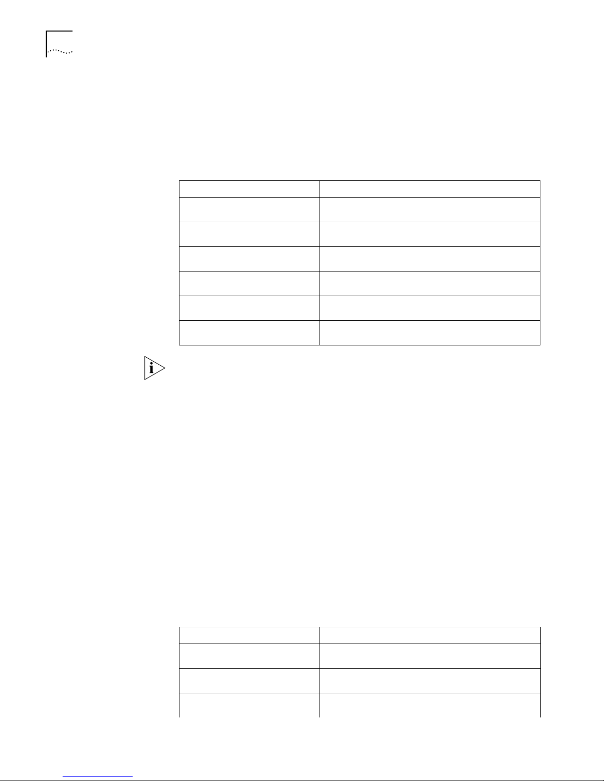
Ta bl e 11 Adding the Ethernet Port to Specified VLANs
Operation Command
Add the current access port to a
specified VLAN
Add the current hybrid port to
specified VLANs
Add the current trunk port to
specified VLANs
Remove the current access port
from to a specified VLAN.
Remove the current hybrid port
from to specified VLANs.
Remove the current trunk port
from specified VLANs.
port access vlan vlan_id
port hybrid vlan vlan_id_list {tagged | untagged}
port trunk permit vlan {vlan_id_list | all}
undo port access vlan
undo port hybrid vlan vlan_id_list
undo port trunk permit vlan {vlan_id_list | all}
Note: The access port shall be added to an existing VLAN other than VLAN 1. The
VLAN to which Hybrid port is added must have been existed. The one to which
Trunk port is added cannot be VLAN 1.
After adding the Ethernet port to specified VLANs, the local port can forward
packets of these VLANs. The hybrid and trunk ports can be added to multiple
VLANs, thereby implementing the VLAN intercommunication between peers. For
the hybrid port, you can configure to tag some VLAN packets, based on which the
packets can be processed differently.
Setting the Default VLAN ID for Ethernet Port
Since the access port can only be included in one VLAN, its default VLAN is the
one to which it belongs. The hybrid port and the trunk port can be included in
several VLANs, however, it is necessary to configure the default VLAN ID. If the
default VLAN ID has been configured, the packets without VLAN Tag will be
forwarded to the port that belongs to the default VLAN. When sending the
packets with VLAN Tag, if the VLAN ID of the packet is identical to the default
VLAN ID of the port, the system will remove VLAN Tag before sending this packet.
Perform the following configuration in Ethernet port view.
Ta bl e 12 Set the Default VLAN ID for the Ethernet Port
Operation Command
Set the default VLAN ID for the
hybrid port.
Set the default VLAN ID for the
trunk port
Restore the default VLAN ID of the
hybrid port to the default value
port hybrid pvid vlan vlan_id
port trunk pvid vlan vlan_id
undo port hybrid pvid
Page 41
Ethernet Port Overview 33
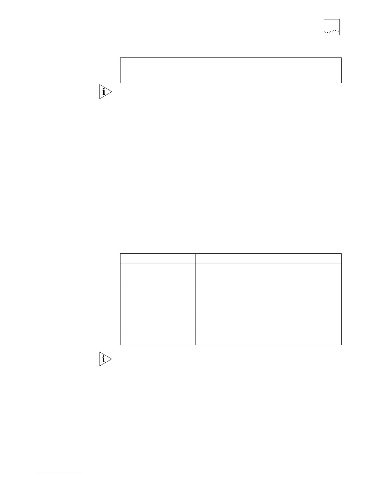
Table 12 Set the Default VLAN ID for the Ethernet Port
Operation Command
Restore the default VLAN ID of the
trunk port to the default value
undo port trunk pvid
Note:
■ The Trunk port and isolate-user-vlan cannot be configured simultaneously,
while the hybrid port and isolate-user-vlan can be thus configured. However, if
the default VLAN has been mapped in isolate-user-vlan, you cannot modify the
default VLAN ID until the mapping relationship has been removed.
■ To guarantee the proper packet transmission, the default VLAN ID of local
hybrid port or Trunk port should be identical with that of the hybrid port or
Trunk port on the peer switch. The VLAN of hybrid port and trunk port is VLAN
1 by default. The access port is the VLAN to which it belongs.
Display and Debug
Ethernet Port
After configuration, execute the display command in all views to display the
current of the Ethernet port parameters, and to verify the configuration.
Execute the reset command in user view to clear the statistics from the port.
Execute the loopback command in Ethernet port view to check whether the
Ethernet port works normally. In the process of the loopback test, the port cannot
forward the packets. The loop test will finish automatically after being executed
for a while.
Ta bl e 13 Display and Debug Ethernet Port
Operation Command
Configure to perform
loopback test on the Ethernet
port.
Display all the information of
the port
Display hybrid port or trunk
port
Display the information of
VLAN VPN
Clear the statistics information
of the port
loopback {external | internal}
display interface {interface_type | interface_type
interface_num | interface_name}
display port {hybrid | trunk}
display port vlan-vpn
reset counters interface [interface_type | interface_type
interface_num | interface_name]
Note: The loopback test cannot be performed on the port disabled by the
shutdown command. During the loopback test, the system will disable speed,
duplex, mdi and shutdown operation on the port. Some ports do not support the
loopback test. If performing this command in these ports, you will see the system
prompt.
Example: Configuring
the Default VLAN ID of
the Trunk Port
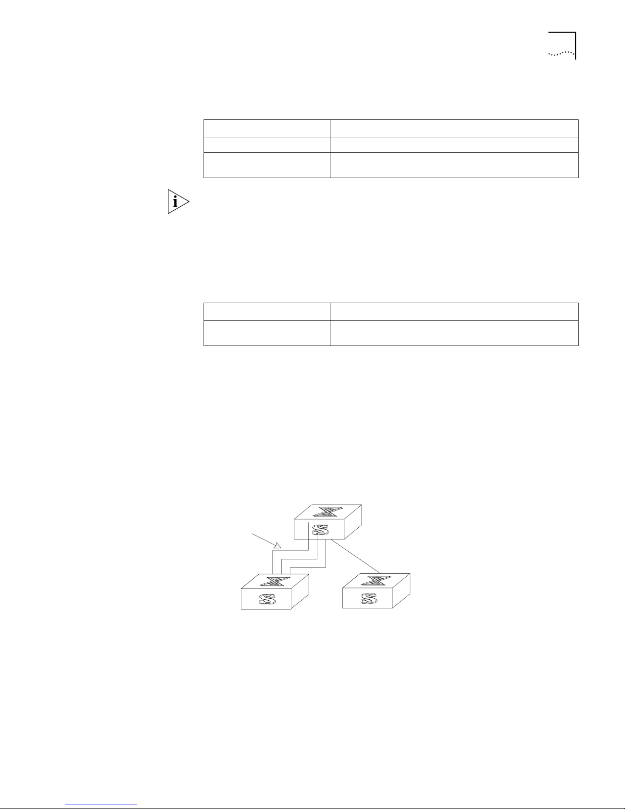
In this example, the Ethernet Switch (Switch A) is connected to the peer (Switch B)
through the trunk port Ethernet1/0/1. This example shows the default VLAN ID for
the trunk port and verifies the port trunk pvid vlan command. As a typical
application of the port trunk pvid vlan command, the trunk port will transmit
the packets without tag to the default VLAN.
Page 42

34 CHAPTER 2: PORT CONFIGURATION
Figure 1 Configure the Default VLAN for a Trunk Port
Ethernet Port
Troubleshooting
Switch A
Switch B
The following configurations are used for Switch A. Configure Switch B in the
similar way.
1 Enter the Ethernet port view of Ethernet1/0/1.
[SW7700] interface ethernet1/0/1
2 Set the Ethernet1/0/1 as a trunk port and allows VLAN 2, 6 through 50, and 100
to pass through.
[SW7700-Ethernet1/0/1] port link-type trunk
[SW7700-Ethernet1/0/1] port trunk permit vlan 2 6 to 50 100
3 Create the VLAN 100.
[SW7700] vlan 100
4 Configure the default VLAN ID of Ethernet1/0/1 as 100.
[SW7700-Ethernet1/0/1] port trunk pvid vlan 100
If the default VLAN ID configuration fails, take the following steps:
1 Execute the display interface or display port command to check if the port is a
trunk port or a hybrid port. If it is neither of them, configure it as a trunk port or a
hybrid port.
2 Then configure the default VLAN ID.
Link Aggregation
Configuration
Link Aggregation
Configuration
Link Aggregation means aggregating several ports together to allow
outgoing/incoming payload balance among member ports. Link aggregation
appears as a single port physically.
The Switch 7700 supports 64 link aggregation groups. For the 48-port
10/100BASE-T auto-sensing fast Ethernet interface card, the first 24 ports can be
aggregated arbitrarily as long as they are assigned contiguously; meaning port 1
to port 2 to port 3 and so on. The same is true for the last 24 ports. For the other
interface cards, you can aggregate no more than the ports provided by each card.
The group can start from any port, as long as the ports in it are consecutive order.
In a link aggregation group, the port with the smallest number serves as the
master port, and the others serve as member ports. In one link aggregation group,
the link type of the master port and the member ports must be identical. That is,
the master port and the member ports should be in Trunk mode together, or be in
Access mode together.
Link aggregation configuration involves aggregating Ethernet ports or removing a
configured link aggregation.
Page 43
Link Aggregation Configuration 35
Perform the following configuration in system view.
Ta bl e 14 Aggregating Ethernet Ports
Operation Command
Aggregate Ethernet ports link-aggregation port_num1 to port_num2 {both | ingress}
Remove a configured link
aggregation
undo link-aggregation {master_port_num | all}
Note: The Ethernet ports to be aggregated should be configured with the same
speed and duplex otherwise, they cannot be aggregated. The Switch 7700 does
not support ingress aggregation mode.
Display and Debug Link
Aggregation
Example: Configuring
Link Aggregation
After the previous configuration, execute the display command in all views to
display the running of the link aggregation configuration, and to verify the effect
of the configuration.
Ta bl e 15 Display the Information of the Link Aggregation
Operation Command
Display the information of the
link aggregation
display link-aggregation [master_port_num]
The following example uses the link aggregation commands to aggregate several
ports and implements the outgoing/incoming payload balance among all the
member ports. The link aggregation is typically used for Trunk ports. Since the
Trunk port allows frames from several VLANs to pass through, the heavy traffic
needs balancing among all the ports.
Ethernet Switch (Switch A) is connected to the Ethernet Switch (Switch B)
upstream via the aggregation of three ports, Ethernet1/0/1 through Ethernet1/0/3.
Figure 2 Configure Link Aggregation
Switch B
Link Aggregation
The following configurations are for Switch A. Configure Switch B the same way.
1 Aggregate Ethernet1/0/1 through Ethernet1/0/3.
[SW7700] link-aggregation ethernet1/0/1 to ethernet1/0/3 both
2 Display the information of the link aggregation.
[SW7700] display link-aggregation ethernet1/0/1
Master port: Ethernet1/0/1
Other sub-ports:
Ethernet1/0/2
Ethernet1/0/3
Switch A
Switch C
Page 44

36 CHAPTER 2: PORT CONFIGURATION
Mode: both
Ethernet Link
Aggregation
Troubleshooting
When configuring link aggregation, you might see a message that the
configuration has failed. To address this situation:
■ Check the input parameter and see whether the starting number of Ethernet
port is smaller than the end number. If yes, take the next step.
■ Check whether the Ethernet ports that are in the configured range belong to
any other existing link aggregations. If not, take the next step.
■ Check whether the ports to be aggregated operate in the same speed and full
duplex mode. If yes, take the next step.
■ If correct, configure the link aggregation again.
Page 45

VLAN CONFIGURATION
3
VLAN Overview A virtual local area network (VLAN) groups the devices of a LAN logically, but not
physically, into segments to implement the virtual workgroups.
Using VLAN technology, network managers can logically divide the physical LAN
into different broadcast domains. Every VLAN contains a group of workstations
with the same demands. The workstations of a VLAN do not have to belong to the
same physical LAN segment.
With VLAN technology, the broadcast and unicast traffic within a VLAN will not be
forwarded to other VLANs, so VLAN configurations are very helpful in controlling
network traffic, saving device investment, simplifying network management and
improving security.
Configuring VLAN To configure a VLAN:
■ Create or Delete a VLAN
■ Add Ethernet Ports to a VLAN
■ Specify the Broadcast Suppression Ratio for VLAN
■ Set or Delete VLAN Description Character String
■ Specify or Remove VLAN Interfaces
■ Assign or Delete the IP Address and Mask of a VLAN Interface
■ Shut down or Enable the VLAN Interface
Create or Delete a VLAN
You can use the following command to create or delete a VLAN.
Perform the following configurations in system view.
Ta bl e 1 Create or Delete a VLAN
Operation Command
Create a VLAN and enter the
VLAN view
Delete the specified VLAN undo vlan vlan_id
If the VLAN to be created exists already, enter the VLAN view directly. Otherwise,
create the VLAN first, and then enter the VLAN view.
vlan vlan_id
The vlan_id parameter specifies the VLAN ID. Note that the default VLAN, namely
VLAN 1, cannot be deleted.
Page 46

38 CHAPTER 3: VLAN CONFIGURATION
Add Ethernet Ports to a VLAN
You can use the following command to add Ethernet ports to a VLAN.
Perform the following configuration in VLAN view.
Ta bl e 2 Add Ethernet Ports to a VLAN
Operation Command
Add Ethernet ports to a VLAN port { interface_type interface_num | interface_name [
Remove Ethernet ports from a
VLAN
For the meanings of the parameters related to the Ethernet ports and the specific
numbering rules of the ports, see
The port number following the key word to shall be no smaller than that before
to. And all the ports within the specified range shall be of the same type and exist.
to interface_type interface_num | interface_name ] }& <
1-10 >
undo port { interface_type interface_num |
interface_name [ to interface_type interface_num |
interface_name ] }& < 1-10 >
“Port Configuration” in this manual.
The &<1-10> of the command specifies the repetition times of the parameter,
ranging from 1 to 10. In addition, you cannot specify any trunk ports.
By default, the system adds all the ports to a default VLAN, whose ID is 1.
Specify the Broadcast Suppression Ratio for VLAN
You can use the following command to specify the broadcast suppression ratio for
the VLAN.
Perform the following configuration in VLAN view.
Ta bl e 3 Set Broadcast Suppression Ratio for VLAN
Operation Command
Specify the broadcast suppression
ratio for the VLAN.
Restore the default broadcast
suppression ratio for the VLAN.
broadcast-suppression max-ratio
undo broadcast-suppression
Using this command, you can set the threshold for broadcast traffic that can pass
through the VLAN. This value is represented by the following percent: broadcast
traffic/the entire traffic passed this VLAN. The system discards the traffic that
exceeds the threshold to keep the broadcast traffic in a rational limit and maintain
the normal operation of network services.
The lower the value of the max-ratio parameter, the less broadcast traffic is
allowed to pass through. When it takes 100, the broadcast suppression will not be
performed on the specified VLAN.
By default, no broadcast suppression will be performed on any VLAN, that is, the
max-ratio takes 100.
Page 47

VLAN Overview 39
Set or Delete VLAN Description Character String
You can use the following command to set or delete VLAN description character
string.
The description character strings, such as workgroup name and department name,
are used to distinguish the different VLANs.
Perform the following configuration in VLAN view.
Ta bl e 4 Setting and Deleting VLAN Description Character String
Operation Command
Set the description character
string for the specified VLAN
Delete the description
character string of the
specified VLAN
description string
undo description
By default, the description character string is null.
Specify or Remove VLAN Interfaces
You can use the following command to specify or remove the VLAN interfaces.
Perform the following configurations in system view.
Ta bl e 5 Specifying and Removing VLAN interfaces
Operation Command
Create a new VLAN interface
and enter VLAN interface view
Remove the specified VLAN
interface
interface vlan-interface vlan_id
undo interface vlan-interface vlan_id
Create a VLAN first before create an interface for it.
For this configuration task, vlan_id takes the VLAN ID.
Assign or Delete the IP Address and Mask of a VLAN Interface
To implement the network layer function on a VLAN interface, the VLAN interface
must have a IP address and mask. you can use the following command to set or
delete the IP address and mask for the VLAN interface.
Perform the following configuration in VLAN interface view.
Ta bl e 6 Assign or Delete the IP address and Mask of a VLAN Interface
Operation Command
Assign the IP address and
mask for a VLAN interface
Delete the IP address and mask
of a VLAN interface
ip address ip_address ip_netmask
undo ip address [ ip_address ip_netmask ]
Shut down or Enable the VLAN Interface
You can use the following command to shut down or enable VLAN interfaces.
Page 48
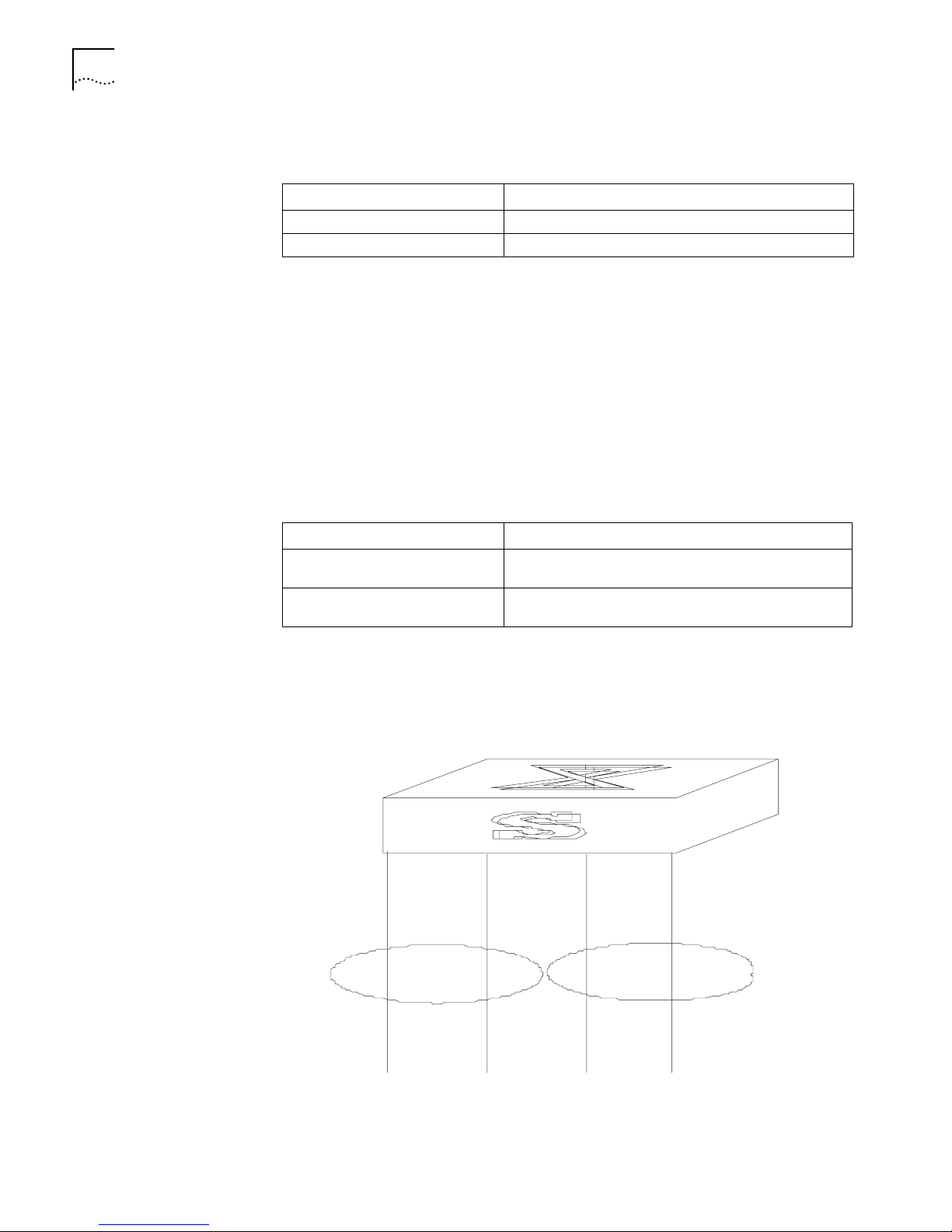
40 CHAPTER 3: VLAN CONFIGURATION
Perform the following configuration in VLAN interface view.
Ta bl e 7 Shut Down or Enable a VLAN interface
Operation Command
Shut down the VLAN interface shutdown
Enabling the VLAN interface undo shutdown
The operation of shutting down or enabling the VLAN interface has no effect on
the status of the Ethernet ports on the local VLAN.
By default, when all the Ethernet ports belonging to a VLAN are down, this VLAN’s
interface is also down and this VLAN interface is shut down. When there is one or
more Ethernet ports enabled, the VLAN’s interface is also enabled, and the VLAN
interface is enabled.
Display and Debug
VLAN
Example: VLAN
Configuration
After the configuring the VLAN, execute the display command in all views to
display the running of the VLAN configuration, and to verify the effect of the
configuration.
Ta bl e 8 Display and Debug VLAN
Operation Command
Display the related information
about VLAN
Display the related information
about VLAN
display interface VLAN-interface [ vlan_id ]
display vlan[ vlan_id | all | static | dynamic ]
Create VLAN2 and VLAN3. Add Ethernet 1/0/1 and Ethernet 2/0/1 to VLAN2 and
add Ethernet 1/0/2 and Ethernet 2/0/2 to VLAN3.
Figure 1 VLAN Configuration Example
Switch
E1/0/1
E2/0/1 E1/0/2 E2/0/2
VLAN2
1 Create VLAN 2 and enters its view.
[SW7700] vlan 2
2 Add Ethernet 1/0/1 and Ethernet 2/0/1 to VLAN2.
VLAN3
Page 49

GARP/GVRP Configuration 41
[SW7700-vlan2] port Ethernet 1/0/1 Ethernet 2/0/1
3 Create VLAN 3 and enters its view.
[SW7700-vlan2] vlan 3
4 Add Ethernet 1/0/2 and Ethernet 2/0/2 to VLAN3.
[SW7700-vlan3] port Ethernet 1/0/2 Ethernet 2/0/2
GARP/GVRP
Configuration
Generic Attribute Registration Protocol (GARP), offers a mechanism that is used by
the members in the same switching network to distribute, propagate, and register
information such as VLAN and multicast addresses.
GARP does not exist in a switch as an entity. A GARP participant is called a GARP
application. The main GARP applications are GVRP and GMRP. GVRP is described
GARP/GVRP Configuration and GMRP is described in Multicast Configuration.
in
When a GARP participant is on a port of the switch, each port corresponds to a
GARP participant.
Through the GARP mechanism, the configuration information on one GARP
member is advertised rapidly in the whole switching network. A GARP member
can be a terminal workstation or bridge. A GARP member can notify other
members to register or remove its attribute information by sending declarations or
withdrawal declarations. It can also register or remove the attribute information of
other GARP members according to the received declarations or withdrawal
declarations.
GARP members exchange information by sending messages. There are three main
types of GARP messages, including join, leave, and leaveall. When a GARP
participant wants to register its attribute information on other switches, it sends a
join message outward. When it wants to remove attribute values from other
switches, it sends a leave message. The leaveall timer is started at the same time
that each GARP participant is enabled and a leaveall message is sent at timeout.
The join and leave messages cooperate to ensure the logout and the
re-registration of a message. By exchanging messages, all the attribute
information to be registered can be propagated to all the switches in the same
switching network.
The destination MAC addresses of the packets of the GARP participants are
specific multicast MAC addresses. A GARP-supporting switch classifies the packets
received from the GARP participants and processes them with the corresponding
GARP applications (GVRP or GMRP).
GARP and GMRP are described in details in the IEEE 802.1p standard (which has
been added to the IEEE 802.1D standard). The Switch 7700 fully supports the
GARP compliant with the IEEE standards.
Note:
■ The value of the GARP timer is used in all the GARP applications, including
■ In one switching network, the GARP timers on all the switching devices should
GVRP and GMRP, running in one switching network.
be set to the same value. Otherwise, the GARP application cannot work
normally.
Page 50

42 CHAPTER 3: VLAN CONFIGURATION
Setting the GARP Timer
GARP timers include the hold, join, leave, and leaveall timers.
The GARP participant sends join message regularly when join timer times out so
that other GARP participants can register its attribute values.
When the GARP participant wants to remove some attribute values, it sends a
leave message outward. The GARP participant receiving the information starts the
leave timer. If a join message is not received again before the leave timer expires,
the GARP attribute values are removed
The leaveall timer is started as soon as the GARP participant is enabled. A leaveall
message is sent at timeout so that other GARP participants remove all the
attribute values of this participant. Then, the leaveall timer is restarted and a new
cycle begins.
When the switch receives GARP registration information, it does not send a join
Message immediately. Instead, it will enable a hold timer and send the Join
message outward at timeout of the hold timer. In this way, all the VLAN
registration information received within the time specified by the hold timer can
be sent in one frame to save bandwidth.
Configure the hold, join, and leave timers in Ethernet port view.
Ta bl e 9 Set the GARP Timer
Operation Command
Set GARP hold, join, and leave
timers
Set GARP leaveall timer garp timer leaveall timer_value
Restore the default GARP hold,
join, and leave timer settings
Restore the default GARP leaveall
timer settings.
garp timer { hold | join | leave } timer_value
undo garp timer { hold | join | leave }
undo garp timer leaveall
Configure the leaveall timer in system view.
Note that the value of the join timer should be no less than the doubled value of
the hold timer, and the value of the leave timer should be greater than the
doubled value of the join timer and smaller than the leaveall timer value.
Otherwise, the system displays an error message.
By default, the hold timer is 10 centiseconds, the join timer is 20 centiseconds, the
leave timer is 60 centiseconds, and the leaveall timer is 1000 centiseconds.
Display and Debug GARP
After you configure the GARP timer, execute the display command in all views to
display the GARP configuration, and to verify the effect of the configuration.
Execute the reset command in the user view to reset the GARP configuration.
Execute the debugging command in user view to debug the GARP configuration.
Ta bl e 10 Display and Debug GARP
Operation Command
Display GARP statistics information display garp statistics [ interface interface-list ]
Page 51

GARP/GVRP Configuration 43
Table 10 Display and Debug GARP
Operation Command
Display GARP timer display garp timer [ interface interface-list ]
Reset GARP statistics information reset garp statistics [ interface interface-list ]
Enable GARP event debugging debugging garp event
Disable GARP event debugging undo debugging garp event
Configuring GVRP GARP VLAN Registration Protocol (GVRP) is a GARP application. Based on the
GARP operating mechanism, GVRP maintains the dynamic VLAN registration
information in the switch and distributes the information to other switches. All
the GVRP-supporting switches can receive VLAN registration information from
other switches and can dynamically update the local VLAN registration
information including the active members and the port through which those
members can be reached. All the GVRP-supporting switches can distribute their
local VLAN registration information to other switches so that VLAN information is
consistent on all GVRP-supporting devices in one switching network. The VLAN
registration information distributed by GVRP includes both the local static
registration information that is configured manually and the dynamic registration
information from other switches.
GVRP is described in details in the IEEE 802.1Q standard. The Switch 7700 fully
supports the GARP compliant with the IEEE standards.
Main GVRP configuration steps include:
■ Enable or Disable Global GVRP
■ Enable or Disable Port GVRP
■ Set GVRP Registration Type
In these configuration tasks, GVRP should be enabled globally before it is enabled
on the port. Configuration of the GVRP registration type can only take effect after
the port GVRP is enabled. In addition, GVRP must be configured on the Trunk
port.
Enable or Disable Global GVRP
You can use the following command to enable or disable global GVRP.
Perform the following configurations in system view.
Ta bl e 11 Enable/Disable Global GVRP
Operation Command
Enable global GVRP gvrp
Disable global GVRP, as
defaulted.
undo gvrp
By default, global GVRP is disabled.
Enable or Disable Port GVRP
You can use the following commands to enable or disable GVRP on a port.
Page 52

44 CHAPTER 3: VLAN CONFIGURATION
Perform the following configurations in Ethernet port view.
Ta bl e 12 Enable/Disable Port GVRP
Operation Command
Enable port GVRP gvrp
Disable port GVRP undo gvrp
GVRP should be enabled globally before it is enabled on the port. GVRP can only
be enabled or disabled on a Trunk port.
By default, global GVRP is disabled.
Set GVRP Registration Type
The GVRP registration types include normal, fixed and forbidden (see IEEE
802.1Q).
■ When an Ethernet port is set to be in normal registration mode, the dynamic
■ When one Trunk port is set as fixed, the system adds the port to the VLAN if a
and manual creation, registration ,and logout of VLAN are allowed on this port.
static VLAN is created on the switch and the Trunk port allows the VLAN
passing. GVRP also adds this VLAN item to the local GVRP database, one link
table for GVRP maintenance. However, GVRP cannot learn dynamic VLAN
through this port. The learned dynamic VLAN from other ports of the local
switch will not be able to send statements to the outside through this port.
■ When an Ethernet port is set to forbidden registration mode, all the VLANs
except VLAN1 are logged out and no other VLANs can be created or registered
on this port.
Perform the following configurations in Ethernet port view.
Ta bl e 13 Set GVRP Registration Type
Operation Command
Set GVRP registration type gvrp registration { normal | fixed | forbidden }
Set the GVRP registration type back
to the default setting
undo gvrp registration
By default, the GVRP registration type is normal.
Display and Debug GVRP
After you set the GVRP registration type, execute the display command in all
views to display the running of the GVRP configuration, and to verify the effect of
the configuration. Execute the debugging command in user view to debug the
configuration of GVRP.
Ta bl e 14 Display and Debug GVRP
Operation Command
Display GVRP statistics information. display gvrp statistics [ interface interface-list ]
Display GVRP global status
information.
Enable GVRP packet or event
debugging
display gvrp status
debugging gvrp { packet | event}
Page 53
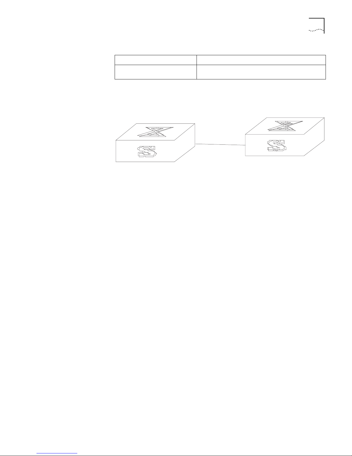
Table 14 Display and Debug GVRP
Operation Command
Disable GVRP packet or event
debugging
undo debugging gvrp { packet | event}
GARP/GVRP Configuration 45
Example: GVRP
Configuration Example
The network requirement is to dynamically register and update VLAN information
among switches.
Figure 2 GVRP Configuration Example
E1/01
Switch A
E2/0/1
Switch B
Configure Switch A:
1 Set Ethernet1/0/1 as a Trunk port and allows all the VLANs to pass through.
[SW7700] interface Ethernet 1/0/1
[SW7700-Ethernet1/0/1] port link-type trunk
[SW7700-Ethernet1/0/1] port trunk permit vlan all
2 Create VLANs.
[SW7700-Ethernet1/0/1] vlan 3
[SW7700-vlan3] vlan 4
3 Enable GVRP globally.
[SW7700-vlan4] quit
[SW7700] gvrp
4 Enable GVRP on the Trunk port.
[SW7700] interface Ethernet 1/0/1
[SW7700-Ethernet1/0/1] gvrp
Configure Switch B:
1 Set Gigabit Ethernet2/1 as a Trunk port and allows all the VLANs to pass through.
[SW7700] interface Ethernet 2/0/1
[SW7700-Ethernet2/0/1] port link-type trunk
[SW7700-Ethernet2/0/1] port trunk permit vlan all
2 Enable GVRP globally.
[SW7700-Ethernet2/0/1] quit
[SW7700] gvrp
3 Enable GVRP on the Trunk port.
[SW7700] interface ethernet 2/0/1
[SW7700-Ethernet2/0/1] gvrp
Page 54

46 CHAPTER 3: VLAN CONFIGURATION
Page 55

NETWORK PROTOCOL OPERATION
4
This chapter covers the following topics:
■ Configure IP Address
■ ARP Configuration
■ DHCP Relay
■ IP Performance
Configure IP Address IP address is a 32-bit address represented by four octets. IP addresses are divided
into five classes: A, B, C, D and E. The octets are set according to the first a few
bits of the first octet.
The rule for IP address classification is described as follows:
■ Class A addresses are identified with the first bit of the first octet being 0.
■ Class B addresses are identified with the first bit of the first octet being 10.
■ Class C addresses are identified with the first bit of the first octet being 110.
■ Class D addresses are identified with the first bit of the first octet being 1110.
■ Class E addresses are identified with the first bit of the first octet being 11110.
Addresses of Classes A, B and C are unicast addresses. The Class D addresses are
multicast addresses and Class E addresses are reserved for future uses.
At present, IP addresses are mostly of Class A, Class B and Class C. IP addresses of
Classes A, B and C are composed of two parts: network ID and host ID. Their
network ID lengths are different.
■ Class A IP addresses use only the first octet to indicate the network ID.
■ Class B IP addresses use the first two octets to indicate the network ID.
■ Class C IP addresses use the first three octets to indicate the network ID.
At most, there are: 28 =128 Class A addresses, 216=16384 Class B addresses and
224=2,097,152 Class C addresses.
The IP address is in dotted decimal format. Each IP address contains 4 integers in
dotted decimal notation. Each integer corresponds to one byte,
e.g.,10.110.50.101.
Subnet and Mask IP protocol allocates one IP address for each network interface. Multiple IP
addresses should can only be allocated to a device which has multiple network
interfaces. IP addresses on a device with multiple interfaces have no relationship
among themselves. One IP address cannot uniquely identify one device.
Page 56

48 CHAPTER 4: NETWORK PROTOCOL OPERATION
With the rapid development of the Internet, IP addresses are depleting very fast.
The traditional IP address allocation method uses up IP addresses with little
efficiency. The concept of mask and subnet was proposed to make full use of the
available IP addresses.
A mask is a 32-bit number corresponding to an IP address. The number consists of
1s and 0s. Principally, these 1s and 0s can be combined randomly. However, the
first consecutive bits are set to 1s when designing the mask. The mask is dividied
into two parts: subnet address and host address. The 1 bits and the mask indicate
the subnet address. The other bits indicate the host address. The mask for Class A
addresses is 255.0.0.0, for Class B addresses is 255.255.0.0, and for Class C
addresses is 255.255.255.0.
The mask can be used to divide a Class A network containing more than
16,000,000 hosts or a Class B network containing more than 60,000 hosts into
multiple small networks. Each small network is called a subnet. For example, for
the Class A network address 10.110.0.0, the mask 255.255.224.0 can be used to
divide the network into 8 subnets: (10.110.0.0, 10.110.32.0, 10.110.64.0, and so
on). Each subnet can contain more than 8000 hosts.
Configure IP Address ■ Configure the host name and the corresponding IP address
■ Configure IP address for a VLAN interface
■ Display and debug IP Address
Configure IP Address and HostName for a Host
Perform the following configuration in System view.
Ta bl e 1 Configure the Host Name and the Corresponding IP Address
Operation Command
Configure the host name and
the corresponding IP address
Delete the host name and the
corresponding IP address
ip host hostname ip-address
undo ip host hostname [ ip-address ]
By default, there is no host name associated to any host IP address.
Configure IP Address of the VLAN Interface
You can configure an IP address for every VLAN interface of the Ethernet Switch.
Perform the following configuration in VLAN interface view.
Ta bl e 2 Configure IP Address for a VLAN Interface
Operation Command
Configure IP address for a
VLAN interface
Delete the IP address of a
VLAN interface
ip address ip-address net-mask [ sub ]
undo ip address [ ip-address net-mask [ sub ] ]
The network ID of an IP address is identified by the mask. For example, the IP
address of a VLAN interface is 129.9.30.42 and the mask is 255.255.0.0. After
performing the "AND" operation for the IP address and the mask, you can assign
that device to the network segment 129.9.0.0.
Page 57
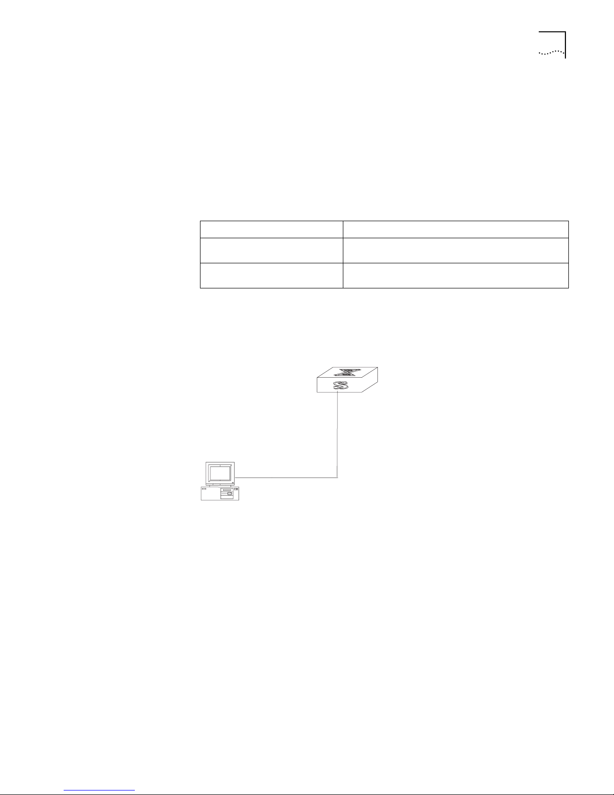
Configure IP Address 49
Generally, it is sufficient to configure one IP address for an interface. However, you
can also configure more than one IP addresses for an interface, so that it can be
connected to several subnets. Among these IP addresses, one is the primary IP
address and all others are secondary.
By default, the IP address of a VLAN interface is null.
Displaying and
Debugging an IP
Address
Example: Configuring
an IP Address
Use the display command in all views to display the IP address configuration on
interfaces, and to verify configuration.
Ta bl e 3 Display and Debug IP Address
Operation Command
Display all hosts on the network
and the corresponding IP addresses
Display the configurations of each
interface
display ip hosts
display ip interface [ interface_type interface_num |
interface_name ]
Configure the IP address as 129.2.2.1 and sub-net mask as 255.255.255.0 for the
VLAN interface 1 of the Ethernet Switch.
Figure 1 IP address Configuration Networking
Switch
Troubleshooting an IP
Address Configuration
Console cable
PC
1 Enter VLAN interface 1.
[3Com] interface vlan 1
2 Configure the IP address for VLAN interface 1.
[3Com-vlan-interface1] ip address 129.2.2.1 255.255.255.0
If the Ethernet Switch cannot ping through a certain host in the LAN:
1 Determine which VLAN includes the port connected to the host. Check whether
the VLAN has been configured with the VLAN interface. Determine whether the IP
address of the VLAN interface and the host are on the same network segment.
2 If the configuration is correct, enable the ARP debugging on the switch, and check
whether the switch can correctly send and receive ARP packets. If it can only send
Page 58

50 CHAPTER 4: NETWORK PROTOCOL OPERATION
but not receive the ARP packets, there are probably errors on the Ethernet physical
layer.
ARP Configuration An IP address cannot be directly used for communication between network
devices because devices can only identify MAC addresses. An IP address is only the
address of a host in the network layer. To send data packets through the network
layer to the destination host, the physical address of the host is required. So the IP
address must be resolved to a physical address.
When two hosts in Ethernet communicate, they must know the MAC addresses of
each other. Every host maintains the IP-MAC address translation table, which is
known as the ARP mapping table. A series of maps between IP addresses and
MAC addresses of other hosts are stored in the ARP mapping table. When an ARP
mapping entry is not in use for a long time, the host will remove it from the
mapping table to save memory space and shorten the search interval.
Example: IP Address
Resolution
Suppose there are two hosts on the Ethernet: Host A and Host B. The IP address of
Host A is IP_A and the IP address of Host B is IP_B. Host A will transmit messages
to Host B. Host A checks its own ARP mapping table first to make sure whether
there are corresponding ARP entries of IP_B in the table. If the corresponding MAC
address is detected, Host A will use the MAC address in the ARP mapping table to
encapsulate the IP packet in frame and send it to Host B. If the corresponding
MAC address is not detected, Host A will store the IP packet in the queue waiting
for transmission, and broadcast it throughout the Ethernet.
The ARP request packet contains the IP address of Host B and IP address and MAC
address of Host A. Since the ARP request packet is broadcast, all hosts on the
Ethernet receive the request. However, only the requested host (i.e., Host B) needs
to process the request. Host B will first store the IP address and the MAC address
of the request sender (Host A) in the ARP request packet in its own ARP mapping
table. Then Host B will generate an ARP reply packet and add MAC address of
Host B to send it to Host A. The reply packet will be sent directly to Host A instead
of being broadcast. Receiving the reply packet, Host A will extract the IP address
and the corresponding MAC address of Host B and add them to its own ARP
mapping table. Then Host A will send Host B all the packets standing in the queue.
Normally, dynamic ARP executes and automatically searches for the resolution
from the IP address to the Ethernet MAC address without the administrator.
Configure Static ARP The ARP mapping table can be maintained dynamically or manually. Addresses
that are mapped manually are referred to as static ARP. The user can display, add,
or delete the entries in the ARP mapping table through manual commands.
The static ARP configuration includes:
■ Manually Add/delete static ARP Mapping Entries
■ Display and debug ARP
Page 59
DHCP Relay 51
Manually Add/Delete Static ARP Mapping Entries
Perform the following configuration in System view.
Ta bl e 4 Manually Add/Delete Static ARP Mapping Entries
Operation Command
Manually add a static ARP mapping
entry
Manually delete a static ARP
mapping entry
arp static ip-address mac-address VLANID {
interface_type interface_num | interface_name }
undo arp static ip-address
Note: Static ARP mapping entries will not time out, however dynamic ARP
mapping entries time out after 20 minutes.
The ARP mapping table is empty and the address mapping is obtained through
dynamic ARP by default.
Displaying and Debugging ARP
After the previous configuration, execute display command in all views to display
the running of the ARP configuration, and to verify the effect of the configuration.
Execute
Ta bl e 5 Display and Debug ARP
debugging command in user view to debug ARP configuration.
Operation Command
Display ARP mapping table display arp [ static | dynamic | ip-address ]
Enable ARP information debugging debugging arp { packet | status }
Disable ARP information debugging undo debugging arp { packet | status }
All ARP mapping entries of the Ethernet switch are displayed by default.
DHCP Relay Dynamic Host Configuration Protocol (DHCP) is used to ease entry and exit to the
network. It is also used to improve the use of the IP addresses in remote locations
or where the host number exceeds the number of allocated IP addresses. DHCP
works in Client-Server mode. With this protocol, the DHCP Client can dynamically
request configuration information and the DHCP server can configure the
information for the Client.
The DHCP relay serves as conduit between the DHCP Client and the server located
on different subnets. The DHCP packets can be relayed to the destination DHCP
server (or Client) across network segments. The DHCP clients on different
networks can use the same DHCP server. This is economical and convenient for
centralized management.
Page 60
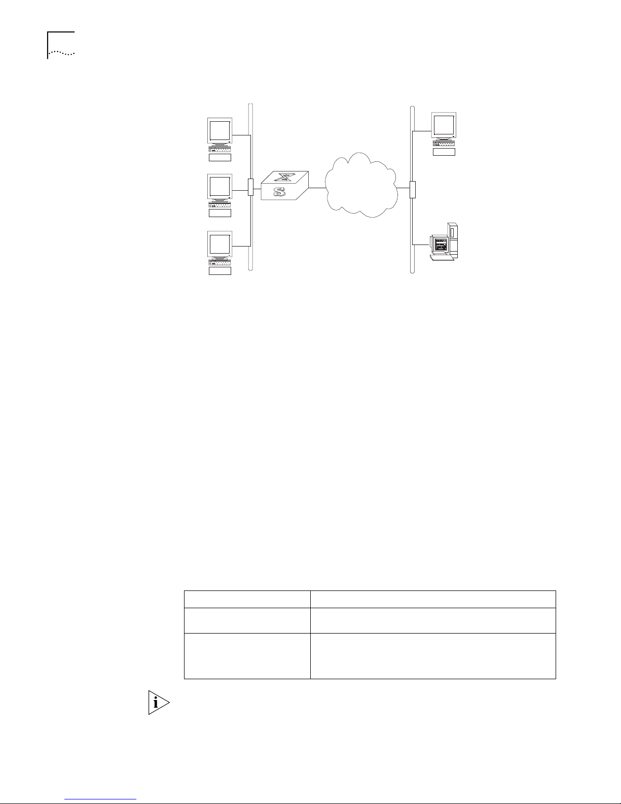
52 CHAPTER 4: NETWORK PROTOCOL OPERATION
DHCP clients
Switch
Intranet
DHCP client
DHCP server
Ethernet
Ethernet
Figure 2 DHCP Relay Schematic Diagram
DHCP client
Ethernet
Intranet
DHCP clients
Switch
When the DHCP Client performs initialization, it broadcasts the request packet on
the local network segment. If there is a DHCP server on the local network segment
(e.g. the Ethernet on the right side of the figure), then the DHCP can be
configured directly without the relay. If there is no DHCP server on the local
network segment, the DHCP relay will process the received broadcast packets and
forward them to DHCP remote servers. The server configures the Clients-Server
according to the information provided by it and transmits the configuration
information to the clients through the DHCP relay, thereby completing the
dynamic configuration for the Client.
Configuring DHCP Relay DHCP relay configuration includes:
■ Configures the corresponding DHCP Server IP Address of a DHCP Server
■ Configures Corresponding DHCP Server Group of the VLAN Interface
■ Configurse the Address Table Entry
■ Enables DHCP security features
Ethernet
DHCP server
■ Configures DHCP broadcast packets snooping function on the switch
(supported by the Layer 2 products S3000/S2000.)
Configure the Corresponding DHCP Server IP Address of a DHCP Server
Perform the following configuration in System view.
Ta bl e 6 Configure/Delete the IP Address of the DHCP Server
Operation Command
Configure the IP address of the
DHCP Server
Remove all the IP addresses of
the DHCP Server (namely, set
the IP addresses of the primary
and secondary servers to 0).
Note: The backup server IP address cannot be configured independently, instead,
it has to be configured together with the master server IP address.
The corresponding IP address of the DHCP Server is not configured by default. The
DHCP Server address must be configured before DHCP relay can be used.
dhcp-server groupNo ip ipaddress1 [ ipaddress2 ]
undo dhcp-server groupNo
Page 61

DHCP Relay 53
Configure Corresponding DHCP Server Group of the VLAN Interface
Perform the following configuration in VLAN interface view.
Ta bl e 7 Configure/Delete the Corresponding DHCP Server Group of VLAN Interface
Operation Command
Configure Corresponding DHCP
Server Group of the VLAN Interface
Delete the corresponding DHCP
server group of the VLAN interface
dhcp-server groupNo
undo dhcp-server
When associating a VLAN interface to a new DHCP server group, you can
configure the association without disassociating it from the previous group.
No VLAN interface corresponds to a DHCP server group, by default.
Configure the Address Table Entry
To check the address of users who have valid and fixed IP addresses in the VLAN
(with DHCP enabled), it is necessary to add an entry in the static address table.
Perform the following configuration in system view.
Displaying and
Debugging DHCP Relay
Ta bl e 8 Configure/Delete the Address Table Entry
Operation Command
Add an entry to the address table dhcp-security ip_address mac_address { dynamic |
static }
Delete an entry from the address
table
undo dhcp-security ip_address
Enable DHCP Security Features
Enable DHCP security features will start address check on VLAN interface while
disable DHCP security features will cancel address check.
Perform the following configuration in VLAN interface view.
Ta bl e 9 Enable/Disable DHCP Security on VLAN Interfaces
Operation Command
Enable DHCP security features enable address-check
Disable DHCP security features on
VLAN interface
disable address-check
After the above configuration, execute display command in all views to display the
running of the DHCP Relay configuration, and to verify the effect of the
configuration. Execute debugging command in user view to debug DHCP Relay
configuration.
Ta bl e 10 Displaying and Debugging DHCP Relay
Operation Command
Display the information about the
DHCP server group
Display the information about the
DHCP server group corresponding
to the VLAN interface.
display dhcp-server groupNo
display dhcp-server interface { interface_type
interface_num | interface_name }
Page 62
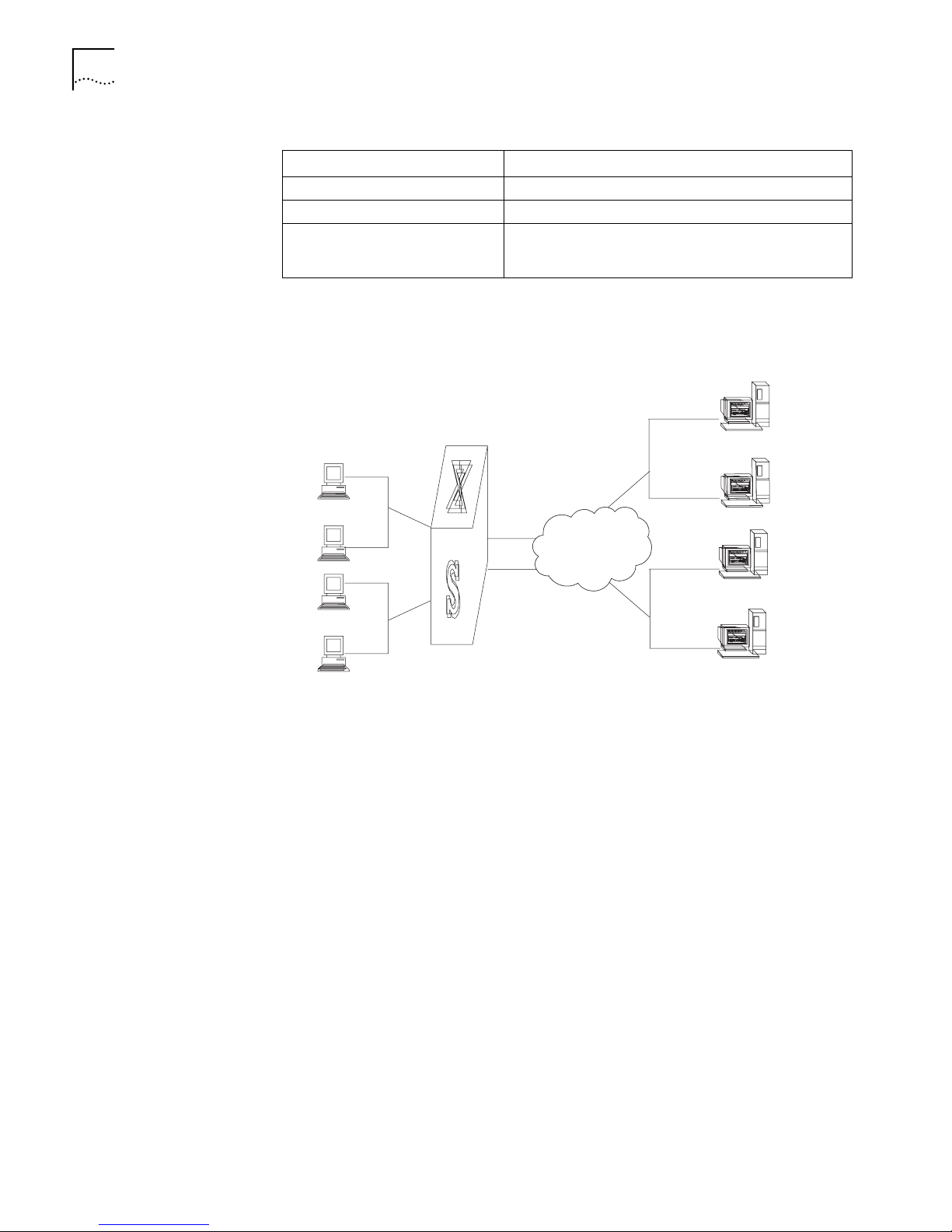
54 CHAPTER 4: NETWORK PROTOCOL OPERATION
Table 10 Displaying and Debugging DHCP Relay
Operation Command
Enable the DHCP relay debugging debugging dhcp-relay
Disable the DHCP relay debugging undo debugging dhcp-relay
Display the address information of
all the legal clients of the DHCP
Server group.
display dhcp-security [ ip_address ]
Example: Configuring
DHCP Relay
Configure the VLAN interface corresponding to the user and the related DHCP
server so as to use DHCP relay.
Figure 3 Networking Diagram of Configuring DHCP Relay
1.99.255.36
1.99.255.35
1.88.255.36
1.88.255.35
VLAN 2
VLAN 3
VLAN
4000
VLAN
3001
Server 1
IP Network
Server 2
1 Configure the IP address corresponding to DHCP Server Group 1.
[3Com] dhcp-server 1 ip 1.99.255.36 1.99.255.35
2 Configure the DHCP Server Group 1 corresponding to the VLAN interface 2.
[3Com-VLAN-Interface2] dhcp-server 1
3 Configure the IP address corresponding to DHCP Server Group 2.
[3Com] dhcp-server 2 ip 1.88.255.36 1.88.255.35
4 Configure the DHCP Server Group 2 corresponding to the VLAN interface 3.
[3Com-VLAN-Interface3] dhcp-server 2
5 Configure the corresponding interface and gateway address of VLAN2.
[3Com] vlan 2
[3Com-vlan2] ❐❏❒▼ ✥▼❈❅❒■❅▼ ✑✏✐✏✒
[3Com] interface vlan 2
[3Com-VLAN-Interface2] ip address 1.1.2.1 255.255.0.0
6 Configure the corresponding interface and gateway address of VLAN3.
[3Com] vlan 3
[3Com-vlan3] port Ethernet 1/0/3
[3Com] interface vlan 3
[3Com-VLAN-Interface3] ip address 21.2.2.1 255.255.0.0
7 It is necessary to configure a VLAN for the server. However, in order to implement
the DHCP relay, the following example configures the servers with the same client
Page 63

DHCP Relay 55
end in different VLANs. The corresponding interface VLAN of the DHCP Server
Group 1 is configured as 4000, and that of the group 2 is configured as 3001.
[3Com] vlan 4000
[3Com-vlan4000] port Ethernet 1/0/4
[3Com] interface vlan 4000
[3Com-VLAN-Interface4000] ip address 1.99.255.1 255.255.0.0
[3Com] vlan 3001
[3Com-vlan3001] port Ethernet 1/0/5
[3Com] interface vlan 3001
[3Com-VLAN-Interface3001] ip address 1.88.255.1 255.255.0.0
8 Show the configuration of DHCP server groups in User view.
<3Com> display dhcp-server 1
9 Show the DHCP Server Group number corresponding to the VLAN interface in
User view.
<3Com> display dhcp-server interface vlan-interface 2
<3Com> display dhcp-server interface vlan-interface 3
Troubleshooting a DHCP
Relay Configuration
If a user cannot apply for IP address dynamically, perform the following procedure:
1 Use the display dhcp-server groupNo command to check if the IP address of the
corresponding DHCP server has been configured.
2 Use the display vlan and display ip commands to check if the VLAN and the
corresponding interface IP address have been configured.
3 Ping the configured DHCP Server to ensure that the link is connected.
4 Ping the IP address of the VLAN interface of the switch to which the DHCP user is
connected from the DHCP server to make sure that the DHCP server can correctly
find the route of the network segment the user is on. If the ping execution fails,
check if the default gateway of the DHCP server has been configured as the
address of the VLAN interface that it locates on.
5 If there is no problem found in the last two steps, use the display dhcp-server
groupNo command to view what packet has been received. If you only see the
Discover packet and there is no response packet, it means the DHCP Server has
not sent the message to the Ethernet Switch. In this case, check if the DHCP Server
has been configured properly. If the numbers of request and response packets are
normal, enable the debugging dhcp-relay in User view and then use the terminal
debugging command output the debugging information to the console. In this
way, you can view the detailed information of all DHCP packets on the console
during applying for the IP address, thereby conveniently locating the problem.
Page 64

56 CHAPTER 4: NETWORK PROTOCOL OPERATION
IP Performance TCP attributes to be configured include:
■ synwait timer: When sending the syn packets, TCP starts the synwait timer. If
response packets are not received before synwait timeout, the TCP connection
will be terminated. The timeout of synwait timer ranges 2 to 600 seconds and
it is 75 seconds by default.
■ finwait timer: When the TCP connection state turns from FIN_WAIT_1 to
FIN_WAIT_2, finwait timer will be started. If FIN packets are not received before
finwait timer timeout, the TCP connection will be terminated. finwait ranges
76 to 3600 seconds and it is 675 seconds by default.
■ The receiving/sending buffer size of connection-oriented Socket is in the range
from 1 to 32K bytes and is 4K bytes by default.
Perform the following configuration in System view.
Ta bl e 11 Configure TCP Attributes
Operation Command
Configure synwait timer time
for TCP connection
establishment
Restore synwait timer time for
TCP connection establishment
to default value
Configure FIN_WAIT_2 timer
time of TCP
Restore FIN_WAIT_2 timer
time of TCP to default value
Configure the Socket
receiving/sending buffer size
of TCP
Restore the socket
receiving/sending buffer size
of TCP to default value
tcp timer syn-timeout time-value
undo tcp timer syn-timeout
tcp timer fin-timeout time-value
undo tcp timer fin-timeout
tcp window window-size
undo tcp window
By default, the TCP finwait timer is 675 seconds, the synwait timer is 75 seconds,
and the receiving/sending buffer size of connection-oriented Socket is 4K bytes.
Displaying and
Debugging IP
Performance
After the previous configuration, display the running of the IP Performance
configuration in all views, and verify the effect of the configuration. Execute the
debugging command in user view to debug IP Performance configuration.
Ta bl e 12 Display and Debug IP Performance
Operation Command
Display TCP connection state display tcp status
Display TCP connection
statistics data
Display the VLAN interface
table information of the IP
layer
display tcp statistics
display ip interface [ interface_type interface_num |
interface_name ]
Page 65

IP Performance 57
Troubleshooting IP
Performance
If the IP layer protocol works normally but TCP and UDP do work normally, you can
enable the corresponding debugging information output to view the debugging
information.
■ Use the terminal debugging command to output the debugging information
to the console.
■ Use the debugging udp command to enable the UDP debugging to trace the
UDP packet. When the router sends or receives UDP packets, the content
format of the packet can be displayed in real time. You can locate the problem
from the contents of the packet.
The following are the UDP packet formats:
UDP output packet:
Source IP address:202.38.160.1
Source port:1024
Destination IP Address 202.38.160.1
Destination port: 4296
■ Use the debugging tcp packet or debugging tcp transaction command to
enable the TCP debugging to trace the TCP packets. There are two available
ways for debugging TCP.
■ Debug and trace the packets of the TCP connection that take this device as one
end.
Operations include:
<3Com> terminal debugging
<3Com> debugging tcp packet
Then the TCP packets received or sent can be checked in real time. Specific
packet formats include:
TCP output packet:
Source IP address:202.38.160.1
Source port:1024
Destination IP Address 202.38.160.1
Destination port: 4296
Sequence number :4185089
Ack number: 0
Flag :SYN
Packet length :60
Data offset: 10
■ Debug and trace the packets located in SYN, FIN or RST.
Operations include:
<3Com> terminal debugging
<3Com> debugging tcp transact
Then the TCP packets received or sent can be checked in real time, and the
specific packet formats are the same as those mentioned above.
Page 66

58 CHAPTER 4: NETWORK PROTOCOL OPERATION
Page 67

5
ROUTING PROTOCOL OPERATION
This chapter covers the following topics:
■ IP Routing Protocol Overview
■ Static Routes
■ RIP
■ OSPF
■ IP Routing Policy
IP Routing Protocol
Overview
Routers select an appropriate path through a network for an IP packet according
to the destination address of the packet. Each router on the path receives the
packet and forwards it to the next router. The last router in the path submits the
packet to the destination host.
In a network, the router regards a path for sending a packet as a logical route unit,
and calls it a hop. For example, in
goes through 3 networks and 2 routers and the packet is transmitted through
three hops and router segments. Therefore, when a node is connected to another
node through a network, there is a hop between these two nodes and these two
nodes are considered adjacent in the Internet. Adjacent routers are two routers
connected to the same network. The number of route segments between a router
and hosts in the same network count as zero. In
represent the hops. A router can be connected to any physical link that constitutes
a route segment for routing packets through the network.
Note: When an Ethernet switch runs a routing protocol, it can perform router
functions. In this guide, a router and its icon represent a generic router or an
Ethernet switch running routing protocols. To improve readability, this will not be
described again
Figure 1, a packet sent from Host A to Host C
Figure 1, the bold arrows
Page 68
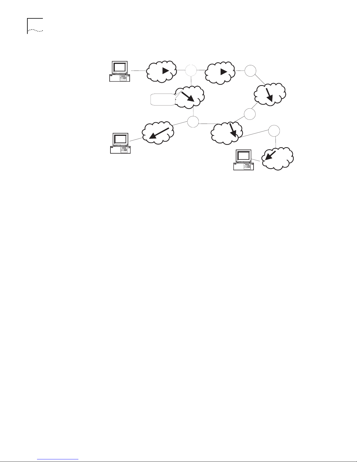
60 CHAPTER 5: ROUTING PROTOCOL OPERATION
Figure 1 About Hops
A
Route
Segment
C
R
R
B
R
R
R
Networks can have different sizes so the segment lengths connected between two
different pairs of routers are also different.
If a router in a network is regarded as a node and a route segment in the Internet
is regarded as a link, message routing in the Internet works in a similar way as the
message routing in a conventional network. Routing a message through the
shortest route may not always be the optimal route. For example, routing through
three LAN route segments may be much faster than a route through two WAN
route segments.
Route Selection through
the Routing Table
Tor the router, a routing table is the key to forwarding packets. Each router saves a
routing table in its memory, and each entry of this table specifies the physical port
of the router through which a packet is sent to a subnet or a host. Therefore, the
packet can reach the next router over a particular path or reach a destination host
through a directly connected network.
A routing table has the following key entries:
■ A destination address — Identifies the destination IP address or the destination
network of the IP packet, which is 32 bits in length.
■ A network mask — Is made up of several consecutive 1s, which can be
expressed either in the dotted decimal format or by the number of the
consecutive 1s in the mask. Combined with the destination address, the
network mask identifies the network address of the destination host or router.
With the destination address and the network mask, you have the address of
the network segment where the destination host or router is located. For
example, if the destination address is 129.102.8.10, the address of the
network where the host or the router with the mask 255.255.0.0 is located is
129.102.0.0.
■ The output interface — Indicates an interface through which an IP packet
should be forwarded.
■ The next hop address — Indicates the next router that an IP packet will pass
through.
Page 69
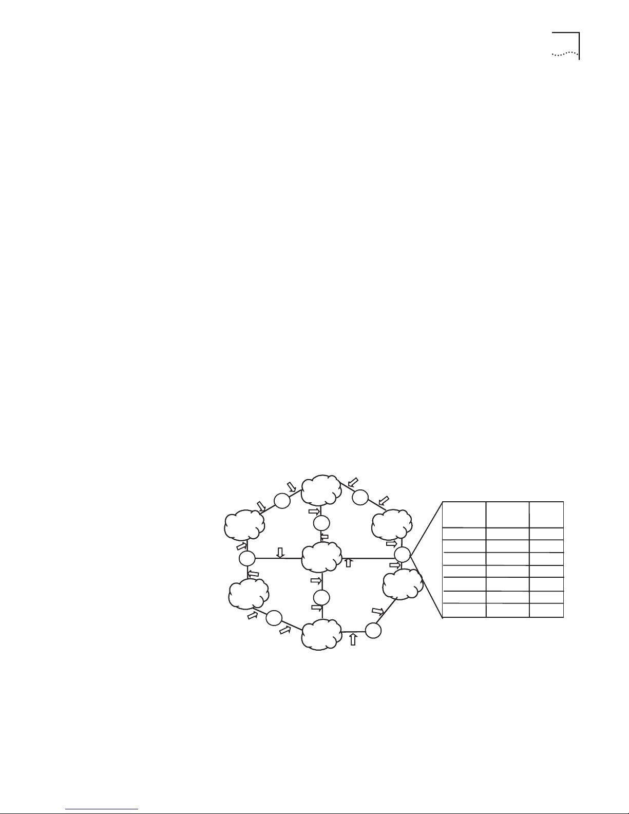
IP Routing Protocol Overview 61
■ The priority added to the IP routing table for a route — Indicates the type of
route that is selected. There may be multiple routes with different next hops to
the same destination. These routes can be discovered by different routing
protocols, or they can be the static routes that are configured manually. The
route with the highest priority (the smallest numerical value) is selected as the
current optimal route.
Types of routes are divided into the following subnet routes, where the destination
is a subnet, or host routes, where the destination is a host.
In addition, depending on whether the network of the destination host is directly
connected to the router, there are the following types of routes:
■ Direct route: The router is directly connected to the network where the
destination is located.
■ Indirect route: The router is not directly connected to the network where the
destination is located.
To limit the size of the routing table, an option is available to set a default route.
All the packets that fail to find a suitable table entry are forwarded through this
default route.
In a complicated Internet as shown in the following figure, the number in each
network is the network address. The router R8 is connected to three networks, so
it has three IP addresses and three physical ports, and its routing table is shown in
Figure 2.
Figure 2 The Routing Table
15.0.0.1
14.0.0.1
15.0.0.2
15.0.0.0
R2
14.0.0.0
12.0.0.3
16.0.0.2
R6
16.0.0.2
13.0.0.2
14.0.0.2
13.0.0.1
12.0.0.2
R1
16.0.0.3
16.0.0.0
R5
13.0.0.0
R3
12.0.0.0
16.0.0.3
13.0.0.3
13.0.0.4
12.0.0.1
R7
10.0.0.1
11.0.0.1
11.0.0.2
R4
10.0.0.2
10.0.0.0
11.0.0.0
R8
Destination
host
location
10.0.0
11.0.0
12.0.0
13.0.0
14.0.0
15.0.0
16.0.0
Forwarding
router
Directly
Directly
11.0.0.2
Directly
13.0.0.2
10.0.0.2
10.0.0.2
Port
passed
2
1
1
3
3
2
2
Routing Management
Policy
The Switch 7700 supports the configuration of a series of dynamic routing
protocols such as RIP, OSPF, as well as the static routes. The static routes
configured by the user are managed together with the dynamic routes as detected
by the routing protocol. The static routes and the routes learned or configured by
routing protocols can also be shared with each other.
Page 70

62 CHAPTER 5: ROUTING PROTOCOL OPERATION
Routing protocols (as well as the static configuration) can generate different
routes to the same destination, but not all these routes are optimal. In fact, at a
certain moment, only one routing protocol can determine a current route to a
single destination. Thus, each routing protocol (including the static configuration)
has a set preference and when there are multiple routing information sources, the
route discovered by the routing protocol with the highest preference becomes the
current route. Routing protocols and the default preferences (the smaller the
value, the higher the preference) of the routes that they learn are shown in
Ta bl e 1.
Ta bl e 1 Routing Protocols and the Default Preferences for Routes
Routing protocol or route type The preference of the corresponding route
DIRECT 0
OSPF 10
STATIC 60
RIP 100
OSPF ASE 150
OSPF NSSA 150
IBGP 256
EBGP 256
UNKNOWN 255
In the table, 0 indicates a direct route, 255 indicates any route from an unreliable
source.
Except for direct routing and BGP (IBGP and EBGP), the preferences of various
dynamic routing protocols can be manually configured to meet the user
requirements. In addition, the preferences for individual static routes can be
different.
Routes Shared Between Routing Protocols
As the algorithms of various routing protocols are different, different protocols can
generate different routes. This situation creates the problem of how to resolve
different routes being generated by different routing protocols. The Switch 7700
supports an operation of importing the routes generated by one routing protocol
into another routing protocol. Each protocol has its own route redistribution
mechanism. For details, refer to
“Configure RIP to Import Routes of Other
Protocols”, “Configure OSPF to Import the Routes of Other Protocols”, or
“Importing Routing Information Discovered by Other Routing Protocols”.
Static Routes A static route is a route that is manually configured by the network administrator.
You can set up an interconnecting network with the static route configuration.
However, when a fault occurs to the network, the static route cannot change
automatically to steer packets away from the node causing the fault without the
help of an administrator.
In a relatively simple network, you only need to configure static routes to make the
router work normally. The proper configuration and usage of the static route can
improve the network performance and ensure the bandwidth of the important
applications.
Page 71

Static Routes 63
The following routes are static routes:
■ Reachable route — The normal route in which the IP packet is sent to the next
hop by the route marked by the destination. It is a common type of static
route.
■ Unreachable route — When a static route to a destination has the reject
attribute, all the IP packets to this destination are discarded, and the originating
host is informed that the destination is unreachable.
■ Blackhole route — When a static route to a destination has the blackhole
attribute, all the IP packets to this destination are discarded, and the originating
host is not informed.
The attributes reject and blackhole are usually used to control the range of
reachable destinations of this router, and to help troubleshoot the network.
Default Route
A default route is a static route, too. A default route is used only when no suitable
routing table entry is found. In a routing table, the default route is in the form of
the route to the network 0.0.0.0 (with the mask 0.0.0.0). You can determine
whether a default route has been set by viewing the output of the display ip
routing-table command. If the destination address of a packet fails to match any
entry of the routing table, the router selects the default route to forward this
packet. If there is no default route and the destination address of the packet fails
to match any entry in the routing table, this packet is discarded, and an Internet
Control Message Protocol (ICMP) packet is sent to the originating host to indicate
that the destination host or network is unreachable.
Configuring Static
Routes
In a typical network that consists of hundreds of routers, significant bandwidth
would be consumed if you used multiple dynamic routing protocols without
configuring a default route. Using the default route can provide appropriate
bandwidth, though not high bandwidth, for communications between large
numbers of users.
Static route configuration tasks are described in the following sections:
■ Configuring a Static Route
■ Configuring a Default Route
Configuring a Static Route
Perform the following configurations in system view.
Ta bl e 2 Configure a Static Route
Operation Command
Add a static route ip route-static ip-address {mask | mask-length } {
interface-name | gateway-address } [ preference value ] [
reject | blackhole ]
Delete a static route undo ip route-static ip-address {mask | mask-length } {
interface-name | gateway-address} [ preference value ]
The parameters are explained as follows:
■ IP address and mask
Page 72

64 CHAPTER 5: ROUTING PROTOCOL OPERATION
The IP address and mask use a decimal format. Because the 1s in the 32-bit
mask must be consecutive, the dotted decimal mask can also be replaced by
the mask-length which refers to the digits of the consecutive 1s in the mask.
■ Transmitting interface or next hop address
When you configure a static route, you can specify either the interface-type
port-number to designate a transmitting interface or the gateway-address to
decide the next hop address, depending on the actual conditions.
You can specify the transmitting interfaces in the cases below:
■ For the interface that supports resolution from the network address to the link
layer address (such as the Ethernet interface that supports ARP), when
ip-address and mask (or mask-length) specifies a host address, and this
destination address is in the directly connected network, the transmitting
interface can be specified.
■ For a P2P interface, the address of the next hop defines the transmitting
interface because the address of the opposite interface is the address of the
next hop of the route.
In fact, for all routing items, the next hop address must be specified. When the
IP layer transmits a packet, it first searches the matching route in the routing
table depending on the destination address of the packet. Only when the next
hop address of the route is specified, can the link layer find the corresponding
link layer address, and then forward the packet.
Display and Debug
Static Route
■ For different configurations of preference-value, you can flexibly apply the
routing management policy.
■ The reject and blackhole attributes indicate the unreachable route and the
blackhole route.
Configuring a Default Route
Perform the following configurations in system view.
Ta bl e 3 Configuring a Default Route
Operation Command
Configure a default route ip route-static 0.0.0.0 { 0.0.0.0 | 0 } { interface-name |
gateway-address } [ preference value ] [ reject |
blackhole ]
Delete a default route undo ip route-static 0.0.0.0 { 0.0.0.0 | 0 } {
interface-name | gateway-address } ]
Parameters for default route are the same as for static route.
After you configure static and default routes, execute the display command in all
views to display the running of the static route configuration, and to verify the
effect of the configuration.
Ta bl e 4 Display and Debug the Routing Table
Operation Command
View routing table summary display ip routing-table
View routing table details display ip routing-table verbose
View the detailed information
of a specific route
display ip routing-table ip-address
Page 73
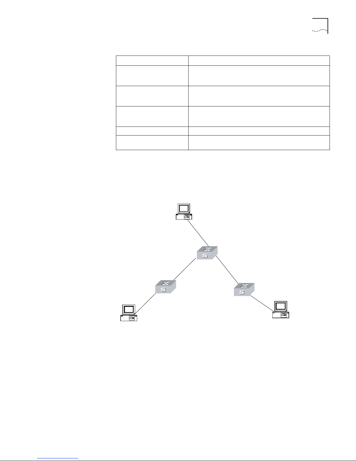
Table 4 Display and Debug the Routing Table
Operation Command
view the route filtered through
specified basic access control
display ip routing-table acl { acl-number | acl-name } [
verbose ]
list (ACL)
view the route information
that through specified ip prefix
display ip routing-table ip-prefix ip-prefix-number [
verbose ]
list
View the routing information
found by the specified
display ip routing-table protocol protocol [ inactive |
verbose ]
protocol
View the tree routing table display ip routing-table radix
view the integrated routing
display ip routing-table statistics
information
Static Routes 65
Example: Typical Static
Route Configuration
As shown in the Figure 3, the masks of all the IP addresses in the figure are
255.255.255.0. All the hosts or switches must be interconnected in pairs by
configuring static routes.
Figure 3 Static Route Configuration
C
Host 1.1.5.1
1.1.5.2/24
1.1.3.1/24
Switch C
1.1.1.2/24
A
Host 1.1.1.1
1.1.2.1/24
Switch A
1.1.3.2/24
Switch B
1.1.4.1/24
Host 1.1.4.2
B
1 Configure the static route for Ethernet Switch A:
[Switch A] ip route-static 1.1.3.0 255.255.255.0 1.1.2.2
[Switch A] ip route-static 1.1.4.0 255.255.255.0 1.1.2.2
[Switch A] ip route-static 1.1.5.0 255.255.255.0 1.1.2.2
2 Configure the static route for Ethernet Switch B:
[Switch B] ip route-static 1.1.2.0 255.255.255.0 1.1.3.1
[Switch B] ip route-static 1.1.5.0 255.255.255.0 1.1.3.1
[Switch B] ip route-static 1.1.1.0 255.255.255.0 1.1.3.1
3 Configure the static route for Ethernet Switch C:
[Switch C] ip route-static 1.1.1.0 255.255.255.0 1.1.2.1
[Switch C] ip route-static 1.1.4.0 255.255.255.0 1.1.3.2
Page 74

66 CHAPTER 5: ROUTING PROTOCOL OPERATION
4 Configure the default gateway of the Host A to be 1.1.1.2
5 Configure the default gateway of the Host B to be 1.1.5.2
6 Configure the default gateway of the Host C to be 1.1.4.1
Using this procedure, all the hosts or switches in Figure 3 can be interconnected in
pairs.
Static Route Fault
Diagnosis and
Troubleshooting
The Switch 7700 is not configured with the dynamic routing protocol, and both
the physical status and the link layer protocol status of the interface is enabled,
but the IP packets cannot be forwarded normally.
■ Use the display ip routing-table protocol static command to view
whether the corresponding static route is correctly configured.
■ Use the display ip routing-table command to view whether the
corresponding route is valid.
RIP Routing Information Protocol (RIP) is a simple, dynamic routing protocol, that is
Distance-Vector (D-V) algorithm-based. It uses hop counts to measure the distance
to the destination host, which is called routing cost. In RIP, the hop count from a
router to its directly connected network is 0. The hop count to a network which
can be reached through another router is 1, and so on. To restrict the time to
converge, RIP prescribes that the cost value is an integer that ranges from 0 to 15.
The hop count equal to or exceeding 16 is defined as infinite, or the destination
network or the host is unreachable.
RIP exchanges routing information via UDP packets. RIP sends a routing refresh
message every 30 seconds. If no routing refresh message is received from one
network neighbor in 180 seconds, RIP tags all routes of the network neighbor as
unreachable. If no routing refresh message is received from one network neighbor
in 300 seconds, RIP removes the routes of the network neighbor from the routing
table. RIP-2 has the MD5 cipher authentication function while RIP-1 does not have
that function.
To improve the performances and avoid route loop, RIP supports split horizon,
poison reverse, and allows for importing routes discovered by other routing
protocols.
Each router running RIP manages a route database, which contains routing entries
to all the reachable destinations in the network. These routing entries contain the
following information:
■ Destination address — The IP address of a host or network.
■ Next hop address — The address of the next router that an IP packet will pass
through for reaching the destination.
■ Output interface — The interface through which the IP packet should be
forwarded.
■ Cost — The cost for the router to reach the destination, which should be an
integer in the range of 0 to 15
■ Timer — The length of time from the last time that the routing entry was
modified until now. The timer is reset to 0 whenever a routing entry is modified
Page 75

RIP 67
■ Route tag — The indication whether the route is generated by an interior
routing protocol or by an exterior routing protocol.
The whole process of RIP startup and operation can be described as follows:
1 If RIP is enabled on a router for the first time, the router broadcasts a request
packet to adjacent routers. When they receive the request packet, adjacent routers
(on which RIP is also enabled) respond to the request by returning the response
packets containing information about their local routing tables.
2 After receiving the response packets, the router that sent the request modifies its
own routing table.
3 RIP broadcasts its routing table to adjacent routers every 30 seconds. The adjacent
routers maintain their own routing tables after receiving the packets and elect an
optimal route, then advertise the modification information to their adjacent
network to make the updated route globally available. Furthermore, RIP uses the
timeout mechanism to handle the timed-out routes to ensure the timeliness and
validity of the routes. With these mechanisms, RIP, an interior routing protocol,
enables the router to learn the routing information of the entire network.
RIP has become one of the most popular standards of transmitting router and host
routes. It can be used in most campus networks and t regional networks that are
simple, yet extensive. For larger and more complicated networks, RIP is not
recommended.
Configuring RIP Only after RIP is enabled can other functional features be configured. But the
configuration of the interface-related functional features is not dependent on
whether RIP has been enabled. It should be noted, however, that after RIP is
disabled, the interface-related features also become invalid.
The RIP configuration tasks are described in the following sections:
■ Enable RIP and Enter the RIP View
■ Enable the RIP Interface
■ Configure Unicast RIP Messages
■ Specify the RIP Version
■ Configure RIP-1 Zero Field Check of the Interface Packet
■ Specify the Operating State of the Interface
■ Disable Host Route
■ Set RIP-2 Route Aggregation
■ Set RIP-2 Packet Authentication
■ Configure Split Horizon
■ Configure RIP to Import Routes of Other Protocols
■ Configure Default Cost for the Imported Route
■ Set the RIP Preference
■ Set Additional Routing Metric
■ Configure Route Filtering
Page 76

68 CHAPTER 5: ROUTING PROTOCOL OPERATION
Enable RIP and Enter the RIP View
Perform the following configurations in system view.
Ta bl e 5 Enable RIP and Enter the RIP View
Operation Command
Enable RIP and enter the RIP view rip
Disable RIP undo rip
By default, RIP is not enabled.
Enable the RIP Interface
For flexible control of RIP operation, you can specify the interface and configure
the network where it is located to the RIP network, so that these interfaces can
send and receive RIP packets.
Perform the following configurations in RIP view.
Ta bl e 6 Enable RIP Interface
Operation Command
Enable RIP on the specified network
interface
Disable RIP on the specified
network interface
network network-address
undo network network-address
Note that after the RIP task is enabled, you should also specify its operating
network segment, for RIP only operates on the interface on the specified network.
For an interface that is not on the specified network, RIP does not receive or send
routes on it, and does not forwards its interface route. The network-address
parameter is the address of the enabled or disabled network, and it can also be
configured as the IP network address of the appropriate interfaces.
When a network command is used for an address, the effect is to enable the
interface of the network with this address. For example, for network
129.102.1.1, you can see network 129.102.0.0 using either the display
current-configuration command or the display rip command.
By default, RIP is disabled on all the interfaces after the router boots.
Configure Unicast RIP Messages
RIP is a broadcast protocol, and to exchange route information with the
non-broadcast network, the unicast transmission mode must be adopted.
Please perform the following configuration in the RIP view.
Ta bl e 7 Configure Unicast RIP Messages
Operation Command
Configure unicast RIP
messages
Cancel unicast RIP messages undo peer ip-address
peer ip-address
By default, RIP does not send any message to any unicast address.
Page 77

RIP 69
Usually, this command is not recommended because the opposite side does not
need to receive two of the same messages at a time. It should be noted that the
peer command should also be restricted by rip work, rip output, rip input and
network commands.
Specify the RIP Version
RIP has two versions, RIP-1 and RIP-2. You can specify the version of the RIP packet
processed by the interface.
RIP-1 broadcasts the packets. RIP-2 can transmit packets by both broadcast and
multicast. By default, multicast is adopted for transmitting packets. In RIP-2, the
default multicast address is 224.0.0.9. The advantage of transmitting packets in
the multicast mode is that the hosts in the same network that do not run RIP do
not receive RIP broadcast packets. In addition, this mode prevents hosts running
RIP-1 from incorrectly receiving and processing the routes with subnet mask in
RIP-2. When an interface is running RIP-2, it can also receive RIP-1 packets.
Perform the following configuration in VLAN interface view.
Ta bl e 8 Specify RIP Version of the Interface
Operation Command
Specify the interface version as
RIP-1
Specify the interface version as
RIP-2
Restore the default RIP version
running on the interface
rip version 1
rip version 2 [ broadcast | multicast ]
undo rip version { 1 | 2 }
By default, the interface receives and sends RIP-1 packets. It transmits packets in
multicast mode when the interface RIP version is set to RIP-2.
Configure RIP-1 Zero Field Check of the Interface Packet
According to the RFC1058, some fields in the RIP-1 packet must be 0. When an
interface version is set to RIP-1, the zero field check must be performed on the
packet. If the value in the zero field is not zero, processing is refused. There are no
zero fields in RIP-2 packets so configuring a zero field check is invalid for RIP-2.
Perform the following configurations in RIP view.
Ta bl e 9 Configure Zero Field Check of the Interface Packet
Operation Command
Configure zero field check on the
RIP-1 packet
Disable zero field check on the
RIP-1 packet
checkzero
undo checkzero
By default, RIP-1 performs zero field check on the packet.
Specify the Operating State of the Interface
In the VLAN interface view, you can specify whether RIP update packets are sent
and received on the interface. In addition, you can specify whether an interface
sends or receives RIP update packets.
Page 78

70 CHAPTER 5: ROUTING PROTOCOL OPERATION
Perform the following configuration in VLAN interface view.
Ta bl e 10 Specify the Operating State of the Interface
Operation Command
Enable the interface to run RIP rip work
Disable the interface to run RIP undo rip work
Enable the interface to receive RIP
update packet
Disable the interface to receive RIP
update packet
Enable the interface to send RIP
update packet
Disable the interface to send RIP
update packet
The rip work command is functionally equivalent to both rip input and rip
output commands.
By default, all interfaces except loopback interfaces both receive and transmit RIP
update packets.
rip input
undo rip input
rip output
undo rip output
Disable Host Route
In some cases, the router can receive many host routes from the same segment,
and these routes are of little help in route addressing but consume a lot of
network resources. Routers can be configured to reject host routes by using undo
host-route command.
Perform the following configurations in RIP view.
Ta bl e 11 Disable Host Route
Operation Command
Enable receiving host route host-route
Disable receiving host route undo host-route
By default, the router receives the host route.
Set RIP-2 Route Aggregation
Route aggregation means that different subnet routes in the same natural
network can be aggregated into one natural mask route for transmission when
they are sent to other, outside networks. Route aggregation can be performed to
reduce the routing traffic on the network as well as to reduce the size of the
routing table.
RIP-1 only sends the route with natural mask, that is, it always sends routes in the
route aggregation form. RIP-2 supports subnet mask and classless inter-domain
routing. To advertise all the subnet routes, the route aggregation function of RIP-2
can be disabled.
Page 79

RIP 71
Perform the following configurations in RIP view.
Ta bl e 12 Route Aggregation
Operation Command
Activate the automatic
aggregation function of RIP-2
Disable the automatic
aggregation function of RIP-2
summary
undo summary
RIP-2 uses the route aggregation function by default.
Set RIP-2 Packet Authentication
RIP-1 does not support packet authentication. However, you can configure packet
authentication on RIP-2 interfaces.
RIP-2 supports two authentication modes:
■ Simple authentication — Does not ensure security. The unencrypted
authentication key is sent with the packet, so simple authentication should not
be applied when there are high security requirements
■ MD5 authentication — Uses two packet formats: One follows RFC1723 (RIP
Version 2 Carrying Additional Information) and another one follows the
RFC2082 (RIP-2 MD5 Authentication).
Perform the following configuration in VLAN interface view
Ta bl e 13 Set RIP-2 Packet Authentication
Operation Command
Configure RIP-2 simple
authentication key
Configure RIP-2 MD5
authentication key
Configure RIP-2 MD5
authentication identifier
Set the packet format type of
RIP-2 MD5 authentication
Cancel authentication of RIP-2
packet
rip authentication-mode simple password-string
rip authentication-mode md5 key-string password-string
rip authentication-mode md5 key-id key-id
rip authentication-mode md5 type {nonstandard | usual}
undo rip authentication-mode
MD5 authentication is applied by default. If the MD5 authentication type is not
specified, the nonstandard packet format type following RFC2082 is applied.
Configure Split Horizon
Split horizon means that the route received through an interface will not be sent
through this interface again. The split horizon algorithm can reduce the
generation of routing loops. But in some special cases, split horizon must be
disabled to obtain correct advertising at the cost of efficiency. Disabling split
horizon has no effect on the P2P connected links but is applicable on the Ethernet.
Page 80

72 CHAPTER 5: ROUTING PROTOCOL OPERATION
Perform the following configuration in VLAN interface view.
Ta bl e 14 Configure Split Horizon
Operation Command
Enable split horizon rip split-horizon
Disable split horizon undo rip split-horizon
By default, split horizon of the interface is enabled.
Configure RIP to Import Routes of Other Protocols
RIP allows users to import the route information of other protocols into the
routing table.
RIP can import direct, static, OSPF, BGP, and other routes.
Perform the following configurations in RIP view.
Ta bl e 15 Configure RIP to Import Routes of Other Protocols
Operation Command
Configure RIP to import routes of
other protocols
Cancel the imported routing
information of other protocols
import-route protocol [ cost value ] [route-policy
route-policy-name ]
undo import-route protocol
By default, RIP does not import the route information of other protocols.
Configure Default Cost for the Imported Route
When you use the import-route command to import the routes of other
protocols, you can specify their cost. If you do not specify the cost of the imported
route, RIP will set the cost to the default cost, specified by the default cost
parameter.
Perform the following configurations in RIP view.
Ta bl e 16 Configure the Default Cost for the Imported Route
Operation Command
Configure default cost for the
imported route
Restore the default cost of the
imported route.
default cost value
undo default cost
By default, the cost value for the RIP imported route is 1.
Set the RIP Preference
Each routing protocol has its own preference, by which the routing policy selects
the optimal one from the routes of different protocols. The greater the preference
value, the lower the preference. The preference of RIP can be set manually.
Page 81

RIP 73
Perform the following configurations in RIP view.
Ta bl e 17 Set the RIP Preference
Operation Command
Set the RIP Preference preference value
Restore the default value of
RIP preference
undo preference
By default, the preference of RIP is 100.
Set Additional Routing Metric
The additional routing metric is the input or output routing metric added to an RIP
route. It does not change the metric value of the route in the routing table, but
adds a specified metric value when the interface receives or sends a route.
Perform the following configuration in VLAN interface view.
Ta bl e 18 Set Additional Routing Metric
Operation Command
Set the additional routing
metric of the route when the
interface receives an RIP
packet
Disable the additional routing
metric of the route when the
interface receives an RIP
packet
Set the additional routing
metric of the route when the
interface sends an RIP packet
Disable the additional routing
metric of the route when the
interface sends an RIP packet
rip metricin value
undo rip metricin
ip metricout value
undo rip metricout
By default, the additional routing metric added to the route when RIP sends the
packet is 1. The additional routing metric when RIP receives the packet is 0 by
default.
Configure Route Filtering
The router provides the route filtering function. You can configure the filter policy
rules by specifying the ACL and ip-prefix for route redistribution and distribution.
Besides, to import a route, the RIP packet of a specific router can also be received
by designating a neighbor router.
Perform the following configurations in RIP view.
Ta bl e 19 Configure RIP to Filter Routes
Operation Command
Configure RIP to Filter Received Routes
Configure filtering the received
routing information distributed by
the specified address
filter-policy gateway ip-prefix-name import
Page 82

74 CHAPTER 5: ROUTING PROTOCOL OPERATION
Table 19 Configure RIP to Filter Routes
Operation Command
Cancel filtering the received
routing information distributed by
the specified address
Configure filtering the received
global routing information
Cancel filtering the received global
routing information
Configure RIP to Filter Distributed Routes
Configure RIP to filter the
distributed routing information
Cancel the RIP filtering of the
routing information
undo filter-policy gateway ip-prefix-name import
filter-policy {acl-number | ip-prefix ip-prefix-name }
import
undo filter-policy { acl-number | ip-prefix
ip-prefix-name } import
filter-policy { acl-number | ip-prefix ip-prefix-name }
export [ routing-protocol ]
undo filter-policy { acl-number | ip-prefix
ip-prefix-name } export [ routing-protocol ]
By default, RIP does not filter received and distributed routing information.
Display and Debug RIP After configuring RIP, execute the display command in all views to display the RIP
configuration, and to verify the effect of the configuration. Execute the
debugging command in user view to debug the RIP module.
Ta bl e 20 Display and Debug RIP
Example: Typical RIP
Configuration
Operation Command
Display the current RIP running
state and configuration
information.
Enable the RIP debugging
information
Enable the debugging of RIP
receiving packet.
Enable the debugging of RIP
sending packet.
display rip
debugging rip packets
debugging rip receive
debugging rip send
As shown in Figure 4, the Switch C connects to the subnet 117.102.0.0 through
the Ethernet port. The Ethernet ports of Switch A and Switch B are connected to
the network 155.10.1.0 and 196.38.165.0, respectively. Switch C, Switch A, and
Switch B are connected by Ethernet 110.11.2.0. Correctly configure RIP to ensure
that Switch C, Switch A, and Switch B can interconnect.
Page 83
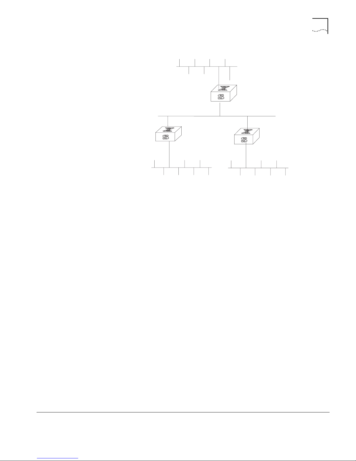
Figure 4 RIP Configuration
Ethernet
Switch C
OSPF 75
Network address:
155.10.1.0/24
Interface address:
155.10.1.1/24
Switch A
Interface address:
110.11.2.1/24
Network address:
110.11.2.2/24
Switch B
RIP Fault Diagnosis and
Troubleshooting
Network address:
196.38.165.0/24
Network address:
117.102.0.0/16
Interface address:
117.102.0.1/16
Interface address:
196.38.165.1/24
Note: The following configuration only shows the operations related to RIP. Before
performing the following configuration, verify that the Ethernet link layer works
normally.
1 Configure RIP on Switch A:
[Switch A] rip
[Switch A-rip] network 110.11.2.0
[Switch A-rip] network 155.10.1.0
2 Configure RIP on Switch B:
[Switch B] rip
[Switch B-rip] network 196.38.165.0
[Switch B-rip] network 110.11.2.0
3 Configure RIP on Switch C:
[Switch C] rip
[Switch C-rip] network 117.102.0.0
[Switch C-rip] network 110.11.2.0
1 The Switch 7700 cannot receive update packets when the physical connection to
the peer routing device is normal.
OSPF Open Shortest Path First (OSPF) is an Interior Gateway Protocol (IGP). At present,
OSPF version 2 (RFC2328) is used, which has the following features:
■ RIP does not operate on the corresponding interface (for example, if the
undo rip work command is executed) or this interface is not enabled
through the network command.
■ The peer routing device is configured for multicast mode (for example, the
rip version 2 multicast command is executed) but the multicast mode has
not been configured on the corresponding interface of the local Ethernet
switch.
Page 84

76 CHAPTER 5: ROUTING PROTOCOL OPERATION
■ Scope — Supports networks in various sizes and can support several hundred
routers
■ Fast convergence — Transmits the update packets instantly after the network
topology changes so the change is synchronized in the AS
■ Loop-free — Calculates routes with the shortest path tree algorithm according
to the collected link states so no loop routes are generated from the algorithm
itself
■ Area partition — Allows the network of AS to be divided into different areas
for management convenience so the routing information that is transmitted
between the areas is further abstracted to reduce network bandwidth
consumption
■ Equal-cost multi-route — Supports multiple equal-cost routes to a destination
■ Routing hierarchy — Supports a four-level routing hierarchy that prioritizes
routes into intra-area, inter-area, external type-1, and external type-2 routes.
■ Authentication — Supports the interface-based packet authentication to
guarantee the security of the route calculation
■ Multicast transmission — Supports multicast addresses to receive and send
packets.
Calculating OSPF Routes The OSPF protocol calculates routes in the following way:
■ Each OSPF-capable router maintains a Link State Database (LSDB), which
describes the topology of the entire AS. According to the network topology
around itself, each router generates a Link State Advertisement (LSA). The
routers on the network transmit the LSAs among themselves by transmitting
the protocol packets to each other. Thus, each router receives the LSAs of other
routers and all these LSAs constitute its LSDB.
■ LSA describes the network topology around a router, so the LSDB describes the
network topology of the entire network. Routers can easily transform the LSDB
to a weighted directed graph, which actually reflects the topology of the whole
network. Obviously, all the routers have a graph that is exactly the same.
■ A router uses the SPF algorithm to calculate the shortest path tree with itself as
the root, which shows the routes to the nodes in the autonomous system. The
external routing information is leave node. A router, which advertises the
routes, also tags them and records the additional information of the
autonomous system. Therefore, the routing tables obtained by different routers
are different.
OSPF supports interface-based packet authentication to guarantee the security of
route calculation. OSPF also transmits and receives packets by IP multicast.
OSPF Packets
OSPF uses five types of packets:
■ Hello Packet
The Hello packet is the most common packet sent by the OSPF protocol. A
router periodically sends it to its neighbor. It contains the values of some
timers, DR, BDR and the known neighbor.
■ Database Description (DD) Packet
Page 85

OSPF 77
When two routers synchronize their databases, they use the DD packets to
describe their own Link State Databases (LSDs), including the digest of each
LSA. The digest refers to the HEAD of an LSA, which can be used to uniquely
identify the LSA. Synchronizing databases with DD packets reduces the traffic
size transmitted between the routers, since the HEAD of an LSA only occupies a
small portion of the overall LSA traffic. With the HEAD, the peer router can
judge whether it has already had the LSA.
■ Link State Request (LSR) Packet
After exchanging the DD packets, the two routers know which LSAs of the
peer routers are missing from the local LSD’s. In this case, they send LSR
packets to the peers, requesting the missing LSAs. The packets contain the
digests of the missing LSAs.
■ Link State Update (LSU) Packet
The LSU packet is used to transmit the needed LSAs to the peer router. It
contains a collection of multiple LSAs (complete contents).
■ Link State Acknowledgment (LSAck) Packet
The packet is used for acknowledging received LSU packets. It contains the
HEAD(s) of LSA(s) requiring acknowledgement.
Basic Concepts Related to OSPF
■ Router ID
To run OSPF, a router must have a router ID. If no ID is configured, the system
automatically selects an IP address from the IP addresses of the current
interface as the router ID.
■ Designated Router (DR)
In a broadcast network, in which all routers are directly connected, any two
routers must establish adjacency to broadcast their local status information to
the whole AS. In this situation, every change that a router makes results in
multiple transmissions, which is not only unnecessary but also wastes
bandwidth. To solve this problem, OSPF defines a “designated router” (DR). All
routers send information only to the DR for broadcasting the network link
states to the network. This reduces the number of router adjacent relations on
the multi-access network.
When the DR is not manually specified, the DR is elected by all the routers in
the segment. See
■ Backup Designated Router (BDR)
“Set the Interface Priority for DR Election”
If the DR fails, a new DR must be elected and synchronized with the other
routers on the segment. This process takes a relatively long time, during which
the route calculation is incorrect. To shorten the process, OSPF creates a BDR as
backup for the DR. A new DR and BDR are elected in the meantime. The
adjacencies are also established between the BDR and all the routers on the
segment, and routing information is also exchanged between them. After the
existing DR fails, the BDR becomes a DR immediately.
■ Area
If all routers on a huge network are running OSPF, the large number of routers
results in an enormous LSDB, which consumes storage space, complicates the
SPF algorithm, and adds CPU load. Furthermore, as a network grows larger, the
Page 86

78 CHAPTER 5: ROUTING PROTOCOL OPERATION
topology becomes more likely to change. Hence, the network is always in
“turbulence”, and a large number of OSFP packets are generated and
transmitted in the network. This shrinks network bandwidth. In addition, each
change causes all the routers on the network to recalculate the routes.
OSPF solves the this problem by dividing an AS into different areas. Areas
logically group the routers, which form the borders of each area. Thus, some
routers may belong to different areas. A router that connects the backbone
area and a non-backbone area is called an area border router (ABR). An ABR
can connect to the backbone area physically or logically.
■ Backbone Area
After the area division of OSPF, one area is different from all the other areas. Its
area-id is 0 and it is usually called the backbone area.
■ Virtual link
Since all the areas should be connected logically, virtual link is adopted so that
the physically separated areas can still maintain logical connectivity.
■ Route summary
An AS is divided into different areas that are interconnected through OSPF
ABRs. The routing information between areas can be reduced by use of a route
summary. Thus, the size of routing table can be reduced and the calculation
speed of the router can be improved. After finding an intra-area route of an
area, the ABR looks in the routing table and encapsulates each OSPF route into
an LSA and sends it outside the area.
OSPF Configuration In various configurations, you must first enable OSPF, specify the interface and
area ID before configuring other functions. But the configuration of the functions
related to the interface is not restricted by whether the OSPF is enabled or not. It
should be noted that after OSPF is disabled, the OSPF-related interface parameters
also become invalid.
OSPF configuration includes the tasks that are described in the following sections:
■ Enable OSPF and Enter OSPF View
■ Enter OSPF Area View
■ Specify Interface
■ Configure Router ID
■ Configure the Network Type on the OSPF Interface
■ Configure the Cost for Sending Packets on an Interface
■ Set the Interface Priority for DR Election
■ Set the Peer
■ Set the Interval of Hello Packet Transmission
■ Set a Dead Timer for the Neighboring Routers
■ Configure an Interval Required for Sending LSU Packets
■ Set an Interval for LSA Retransmission Between Neighboring Routers
■ Set a Shortest Path First (SPF) Calculation Interval for OSPF
■ Configure the OSPF STUB Area
Page 87

OSPF 79
■ Configure NSSA of OSPF
■ Configure the Route Summarization of OSPF Area
■ Configure OSPF Virtual Link
■ Configure Route Summarization Imported into OSPF
■ Configure the OSPF Area to Support Packet Authentication
■ Configure OSPF Packet Authentication
■ Configure OSPF to Import the Routes of Other Protocols
■ Configure Parameters for OSPF to Import External Routes
■ Configure OSPF to Import the Default Route
■ Set OSPF Route Preference
■ Configure OSPF Route Filtering
■ Configure Filling the MTU Field When an Interface Transmits DD Packets
■ Disable the Interface to Send OSPF Packets
■ Reset the OSPF Process
Enable OSPF and Enter OSPF View
Perform the following configurations in system view.
Ta bl e 21 Enable OSPF Process
Operation Command
Enable the OSPF process ospf
Disable the OSPF process undo ospf
By default, OSPF is not enabled.
Enter OSPF Area View
Perform the following configurations in OSPF view.
Ta bl e 22 Enter OSPF Area View
Operation Command
Enter an OSPF area view area area-id
Delete a designated OSPF area undo area area-id
Specify Interface
OSPF divides the AS into different areas. You must configure each OSPF interface
to belong to a particular area, identified by an area ID. The areas transfer routing
information between them through the ABRs.
In addition, parameters of all the routers in the same area should be identical.
Therefore, when configuring the routers in the same area, please note that most
configurations should be based on the area. An incorrect configuration can disable
the neighboring routers from transmitting information, and lead to congestion or
self-loop of the routing information.
Page 88

80 CHAPTER 5: ROUTING PROTOCOL OPERATION
Perform the following configuration in OSPF Area view.
Ta bl e 23 Specify Interface
Operation Command
Specify an interface to run OSPF network ip-address ip-mask
Disable OSPF on the interface undo network ip-address ip-mask
You must specify the segment to which the OSPF will be applied after enabling the
OSPF tasks.
Configure Router ID
A router ID is a 32-bit unsigned integer that uniquely identifies a router within an
AS. A router ID can be configured manually. If a router ID is not configured, the
system selects the IP address of an interface automatically. When you set a router
ID manually, you must guarantee that the IDs of any two routers in the AS are
unique. A common undertaking is to make the router ID the same as the IP
address of an interface on the router.
Perform the following configurations in system view.
Ta bl e 24 Configure Router ID
Operation Command
Configure router ID router id router-id
Remove the router ID undo router id
To ensure the stability of OSPF, the you must determine the division of router IDs
and manually configure them when implementing network planning.
Configure the Network Type on the OSPF Interface
The route calculation of OSPF is based on the topology of the adjacent network of
the local router. Each router describes the topology of its adjacent network and
transmits it to all the other routers.
OSPF divides networks into four types by link layer protocol:
■ Broadcast: If Ethernet or FDDI is adopted, OSFP defaults the network type to
broadcast.
■ Non-Broadcast Muli-access (NBMA): If Frame Relay, ATM, HDLC or X.25 is
adopted, OSPF defaults the network type to NBMA.
■ Point-to-Multipoint (P2MP): OSPF does not default the network type of any link
layer protocol to P2MP. The general undertaking is to change a partially
connected NBMA network to P2MP network if the NBMA network is not
fully-meshed.
■ Point-to-point (P2P): If PPP, LAPB or POS is adopted, OSPF defaults the network
type to P2P.
As you configure the network type, consider the following points:
■ NBMA means that a network is non-broadcast and multi-accessible. ATM is a
typical example. You can configure the polling interval to specify the interval of
Page 89
OSPF 81
the sending polling hello packets before the adjacency of the neighboring
routers is formed.
■ Configure the interface type to nonbroadcast on a broadcast network without
multi-access capability.
■ Configure the interface type to P2MP if not all the routers are directly
accessible on an NBMA network.
■ Change the interface type to P2P if the router has only one peer on the NBMA
network.
The differences between NBMA and P2MP are listed below:
■ In OSPF, NBMA refers to the networks that are fully connected, non-broadcast
and multi-accessible. However, a P2MP network is not required to be fully
connected.
■ DR and BDR are required on a NBMA network but not on a P2MP network.
■ NBMA is the default network type. For example, if ATM is adopted as the link
layer protocol, OSPF defaults the network type on the interface to NBMA,
regardless of whether the network is fully connected. P2MP is not the default
network type. No link layer protocols are regarded as P2MP. You must change
the network type to P2MP manually. The most common method is to change a
partially connected NBMA network to a P2MP network.
■ NBMA forwards packets by unicast and requires neighbors to be configured
manually. P2MP forward packets by multicast.
Perform the following configuration in VLAN interface view.
Ta bl e 25 Configure a Network Type on the Interface that Starts OSPF
Operation Command
Configure network type on the
interface
ospf network-type { broadcast | NBMA | P2MP | P2P }
After the interface has been configured with a new network type, the original
network type of the interface is removed automatically.
Configure the Cost for Sending Packets on an Interface
The user can control the network traffic by configuring different message sending
costs for different interfaces. Otherwise, OSPF automatically calculates the cost
according to the baud rate on the current interface.
Perform the following configuration in VLAN interface view.
Ta bl e 26 Configure the Cost for Sending Packets on the Interface
Operation Command
Configure the cost for sending
packets on interface
Restore the default cost for packet
transmission on the interface
ospf cost value
undo ospf cost
Page 90

82 CHAPTER 5: ROUTING PROTOCOL OPERATION
Set the Interface Priority for DR Election
The priority of the router interface determines the qualification of the interface for
DR election, a router of higher priority is considered first if there is a collision in the
election.
DR is not designated manually, instead, it is elected by all the routers on the
segment. Routers with priorities > 0 in the network are eligible candidates. Among
all the routers self-declared to be the DR, the one with the highest priority is
elected. If two routers have the same priority, the one with the highest router ID is
elected DR. Votes are the hello packets. Each router writes the expected DR in the
packet and sends it to all the other routers on the segment. If two routers
attached to the same segment concurrently declare themselves to be the DR, the
one with the higher priority wins. If the priorities are the same, the router with
higher router ID wins. If the priority of a router is 0, it is not be elected DR or BDR.
If a DR fails, the routers on the network must elect a new DR and synchronize with
the new DR. The process takes a relatively long time, during which, route
calculation can become incorrect. To speed up this DR replacement process, OSPF
implements the BDR as a backup for DR. The DR and BDR are elected at the same
time. The adjacencies are also established between the BDR and all the routers on
the segment, and routing information is also exchanged between them. When the
DR fails, the BDR becomes the DR instantly. Since no re-election is needed and the
adjacencies have already been established, the process is very short. But in this
case, a new BDR must be elected. Although it also takes a long time, it does not
affect the route calculation.
Note that:
■ The DR on the network is not necessarily the router with the highest priority.
Likewise, the BDR is not necessarily the router with the second highest priority.
If a new router is added after DR and BDR election, it is impossible for the
router to become the DR even if it has the highest priority.
■ The DR is based on the router interface in a certain segment. Maybe a router is
a DR on one interface, but it can be a BDR or DROther on another interface.
■ DR election is only required for broadcast or NBMA interfaces. For the P2P or
P2MP interfaces, DR election is not required.
Perform the following configuration in VLAN interface view.
Ta bl e 27 Set the Interface Priority for DR Election
Operation Command
Configure the interface with a
priority for DR election
Restore the default interface
priority
ospf dr-priority priority_num
undo ospf dr-priority
By default, the priority of the interface is 1 in the DR election. The value can be set
from 0 to 255.
Set the Peer
For an NBMA network, some special configurations are required. Since an NBMA
interface on the network cannot discover the adjacent router through
Page 91

OSPF 83
broadcasting the Hello packets, you must manually specify an IP address for the
adjacent router for the interface, and whether the adjacent router is eligible for
election. This can be done by configuring the peer ip-address command. If
dr-priority-number is not specified, the adjacent router will be regarded as
ineligible.
Perform the following configuration in OSPF view.
Ta bl e 28 Configure the Peer
Operation Command
Configure a peer for the NBMA
interface.
Remove the configured peer for the
NBMA interface
peer ip-address [ dr-priority dr-priority-number ]
undo peer ip-address
By default, the preference for the neighbor of NBMA interface is 1.
Set the Interval of Hello Packet Transmission
Hello packets are the most frequently used packets, which are periodically sent to
the adjacent router for discovering and maintaining adjacency, and for electing a
DR and BDR. The user can set the hello timer.
According to RFC2328, the consistency of hello intervals between network
neighbors should be kept. The hello interval value is in inverse proportion to the
route convergence rate and network load.
Perform the following configuration in VLAN interface view.
Ta bl e 29 Set Hello Timer and Poll Interval
Operation Command
Set the hello interval of the
interface
Restore the default hello of the
interface
Set the poll interval on the NBMA
interface
Restore the default poll interval undo ospf timer poll
ospf timer hello seconds
undo ospf timer hello
ospf timer poll seconds
By default, P2P and broadcast interfaces send Hello packets every 10 seconds, and
P2MP and NBMA interfaces send the packets every 30 seconds.
Set a Dead Timer for the Neighboring Routers
The dead timer of neighboring routers refers to the interval after which a router
considers a neighboring router dead if no hello packet is received from it. You can
set a dead timer for the neighboring routers.
Perform the following configuration in VLAN interface view.
Ta bl e 30 Set a Dead Timer for the Neighboring Routers
Operation Command
Configure a dead timer for the
neighboring routers
ospf timer dead seconds
Page 92

84 CHAPTER 5: ROUTING PROTOCOL OPERATION
Table 30 Set a Dead Timer for the Neighboring Routers
Operation Command
Restore the default dead interval of
the neighboring routers
By default, the dead interval for the neighboring routers of P2P or broadcast
interfaces is 40 seconds and for the neighboring routers of P2MP or NBMA
interfaces is 120 seconds.
Note that both hello and dead timers restore the default values if you modify the
network type.
Configure an Interval Required for Sending LSU Packets
Trans-delay seconds should be added to the aging time of the LSA in an LSU
packet. Setting the parameter like this mainly considers the time duration that the
interface requires for transmitting the packet.
You can configure the interval for sending LSU messages. Obviously, more
attention should be paid to this item over low speed network.
undo ospf timer dead
Perform the following configuration in VLAN interface view.
Ta bl e 31 Configure an Interval for LSU packets
Operation Command
Configure an interval for
sending LSU packets
Restore the default interval of
sending LSU packets
ospf trans-delay seconds
undo ospf trans-delay
By default, LSU packets are transmitted by seconds.
Set an Interval for LSA Retransmission Between Neighboring Routers
If a router transmits an LSA to the peer, it requires the acknowledgement packet
from the peer. If it does not receive the acknowledgement packet within the
retransmission, it retransmits this LSA to the neighbor. You can configure the value
of the retransmission interval.
Perform the following configuration in VLAN interface view.
Ta bl e 32 Set Retransmit Timer
Operation Command
Configure the interval of LSA
retransmission for the
neighboring routers
Restore the default LSA
retransmission interval for the
neighboring routers
ospf timer retransmit interval
undo ospf timer retransmit
By default, the interval for neighboring routers to retransmit LSAs is five seconds.
The value of the interval should be bigger than the interval in which a packet can
be transmitted and returned between two routers.
Page 93

OSPF 85
Note that a LSA retransmission interval that is too small will cause unnecessary
retransmission.
Set a Shortest Path First (SPF) Calculation Interval for OSPF
Whenever the OSPF LSDB changes, the shortest path requires recalculation.
Calculating the shortest path after a change consumes enormous resources and
affects the operating efficiency of the router. Adjusting the SPF calculation interval,
however, can restrain the resource consumption caused by frequent network
changes.
Perform the following configuration in OSPF view.
Ta bl e 33 Set the SPF Calculation Interval
Operation Command
Set the SPF calculation interval spf-schedule-interval seconds
Restore the SPF calculation interval undo spf-schedule-interval seconds
By default, the interval FOR SPF recalculation is 5 seconds.
Configure the OSPF STUB Area
STUB areas are special LSA areas in which the ABRs do not propagate the learned
external routes of the AS. In these areas, the routing table sizes of routers and the
routing traffic are significantly reduced.
The STUB area is an optional configuration attribute, but not every area conforms
to the configuration condition. Generally, STUB areas, located at the AS
boundaries, are those non-backbone areas with only one ABR. Even if this area has
multiple ABRs, no virtual links are established between these ABRs.
To insure that routes to the destinations outside the AS are still reachable, the ABR
in this area generates a default route (0.0.0.0) and advertises it to the non-ABR
routers in the area.
Note the following items when you configure a STUB area:
■ The backbone area cannot be configured as a STUB area and the virtual link
cannot pass through the STUB area.
■ If you want to configure an area as a STUB area, all the routers in this area
should be configured with the stub command.
■ No ASBR can exist in a STUB area and the external routes of the AS cannot be
propagated in the STUB area.
Perform the following configuration in OSPF Area view.
Ta bl e 34 Configure an OSPF STUB Area
Operation Command
Configure an area as the STUB area stub [no-summary]
Remove the configured STUB area undo stub
Set the cost of the default route to
the STUB area
default-cost value
Page 94
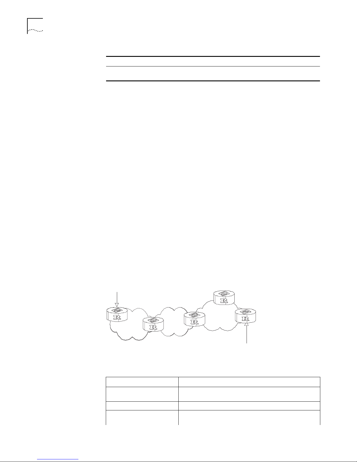
86 CHAPTER 5: ROUTING PROTOCOL OPERATION
Table 34 Configure an OSPF STUB Area
Operation Command
Remove the cost of the default
route to the STUB area
By default, the STUB area is not configured, and the cost of the default route to a
STUB area is 1.
Configure NSSA of OSPF
NSSA and NSSA LSA (also called Type-7 LSA) are transformations of the STUB area
and are highly similar to a STUB area. NSSA does not allow importing
AS-External-LSAs (type-5 LSAs) but it does allow importing AS-External-LSA
(type-7 LSAs).
Type-7 LSAs are generated by the ASBRs in an NSSA, and propagated in the NSSA.
When the type-7 LSAs reach an ABR of the NSSA, the ABR translates the type-7
LSAs into AS-External-LSAs, which is propagated to the other areas.
For example, in Figure 5, the AS running OSPF includes three areas: Area 1, Area 2
and Area 0. Among them, Area 0 is the backbone area. Also, there are other two
ASs running RIP. Area 1 is defined as an NSSA. After RIP routes of Area 1 are
propagated to the NSSA ASBR, the NSSA ASBR generates type-7 LSAs which are
propagated in Area 1. When the type-7 LSAs reach the NSSA ABR, the NSSA ABR
translates it into a type-5 LSA, which is propagated to Area 0 and Area 2. On the
other hand, RIP routes of the AS running RIP are translated into type-5 LSAs that
are propagated in the OSPF AS. However, the type-5 LSAs do not reach Area 1
because Area 1 is an NSSA. NSSAs and STUB areas have the same approach in this
aspect.
undo default-cost
Similar to a STUB area, the NSSA cannot be configured with virtual links.
Figure 5 NSSA
RIP
NSSA
Area 2
Area 0
ABR
Area 1
NSSA
NSSA
ASBR
RIP
Perform the following configuration in OSPF Area view.
Ta bl e 35 Configure NSSA of OSPF
Operation Command
Configure an area to be the
NSSA area
Cancel the configured NSSA undo nssa
Configure the default cost
value of the route to the NSSA
nssa [ default-route-advertise ] [ no-import-route ] [
no-summary ]
default-cost cost
Page 95

OSPF 87
Table 35 Configure NSSA of OSPF
Operation Command
Restore the default cost value
of the route to the NSSA area
undo default-cost
All routers connected to the NSSA must use the nssa command to configure the
area with the NSSA attribute.
The default-route-advertise parameter is used to generate the default type-7
LSAs. The default type-7 LSA route is generated on the ABR, even though the
default route 0.0.0.0 is not in the routing table. On an ASBR, however, the default
type-7 LSA route can be generated only if the default route 0.0.0.0 is in the
routing table.
Executing the no-import-route command on the ASBR prevents the external
routes that OSPF imported through the import-route command from advertising
to the NSSA. Generally, if an NSSA router is both ASBR and ABR, this argument is
used.
The default-cost command is used on the ABR attached to the NSSA. Using this
command, you can configure the default route cost on the ABR to NSSA.
By default, the NSSA is not configured, and the cost of the default route to the
NSSA is 1.
Configure the Route Summarization of OSPF Area
Route summary means that ABR can aggregate information of the routes of the
same prefix and advertise only one route to other areas. An area can be
configured with multiple aggregate segments allowing OSPF to summarize them.
When the ABR transmits routing information to other areas, it generates
Sum_net_Lsa (type-3 LSA) per network. If some continuous networks exist in this
area, you can use the abr-summary command to summarize these segments into
one segment. Thus, the ABR only needs to send an aggregate LSA, and all the
LSAs in the range of the aggregate segment specified by the command are not
transmitted separately. Therefore, the sizes of the LSDBs in other areas can be
reduced.
Once the aggregate segment of a certain network is added to the area, all the
internal routes of the IP addresses in the range of the aggregate segment are no
longer separately broadcast to other areas. Only the route summary of the whole
aggregate network is advertised. But if the range of the segment is restricted by
the not-advertise keyword, the route summary of this segment is not advertised.
This segment is represented by an IP address and mask. The receiving and
restriction of the aggregate segment can reduce the routing traffic exchanged
between the areas.
Route summarization can take effect only when it is configured on ABRs.
Page 96

88 CHAPTER 5: ROUTING PROTOCOL OPERATION
Perform the following configuration in OSPF Area view.
Ta bl e 36 Configure the Route Summarization of an OSPF Area
Operation Command
Configure the Route
Summarization of OSPF Area
Cancel route summarization of
OSPF Area
By default, the inter-area routes are not summarized.
Configure OSPF Virtual Link
According to RFC2328, after the area division of OSPF, The backbone are is
established with an area-id of 0.0.0.0. The OSPF routes between non-backbone
areas are updated with the help of the backbone area. OSPF stipulates that all the
non-backbone areas should maintain connectivity with the backbone area and at
least one interface on the ABR should fall into the area 0.0.0.0. If an area does not
have a direct physical link with the backbone area 0.0.0.0, a virtual link must be
created.
abr-summary ip-address mask [ advertise |
not-advertise ]
undo abr-summary ip-address mask
If physical connectivity cannot be made due to network topology restrictions, a
virtual link can be used to meet the requirements of RFC 2328. The virtual link
refers to a logic channel set up through the area of a non-backbone internal route
between two ABRs. The two ends of the channel should be ABRs and the
connection can take effect only when both ends are configured. The virtual link is
identified by the ID of the remote router. The area, which provides the ends of the
virtual link with a non-backbone area internal route, is called the transit area. The
ID of the transit area should be specified during configuration.
The virtual link is activated after the route passing through the transit area is
calculated, which is equivalent to a P2P connection between two ends. Therefore,
similar to the physical interfaces, you can also configure various interface
parameters on this link, such as a hello timer.
The “logic channel” means that the multiple routers running OSPF between two
ABRs only take the role of packet forwarding (the destination addresses of the
protocol packets are not these routers, so these packets are transparent to them
and the routers forward them as common IP packets). The routing information is
directly transmitted between the two ABRs. The routing information refers to the
type-3 LSAs generated by the ABRs, for which the synchronization mode of the
routers in the area is not changed.
Perform the following configuration in OSPF area view.
Ta bl e 37 Configure OSPF Virtual Link
Operation Command
Create and configure a virtual
link
Remove the created virtual link undo vlink-peer router-id
vlink-peer router-id [ hello seconds] [ retransmit seconds ] [
trans-delay seconds ] [ dead seconds] [ simple password |
md5 keyid key ]
Page 97

OSPF 89
The area-id and router-id variables have no default value. By default, the hello
timer is 10 seconds, retransmit is 5 seconds, trans-delay is 1 second, and the dead
timer is 40 seconds.
Configure Route Summarization Imported into OSPF
The OSPF implementation in the Switch 7700 supports route summarization of
imported routes.
Perform the following configurations in OSPF view.
Ta bl e 38 Configure Route Summarization when Importing Routes into OSPF
Operation Command
Configure summarization of
routes imported into OSPF
Remove summarization of
routes imported into OSPF
asbr-summary ip-address mask [ not-advertise [ tag value ]
| tag value ]
undo asbr-summary ip-address mask [ not-advertise [ tag
value ] | tag value ]
By default, summarization of imported routes is disabled.
After the summarization of imported routes is configured, if the local router is an
autonomous system border router (ASBR), this command summarizes the
imported Type-5 LSAs in the summary address range. When NSSA is configured,
this command also summarizes the imported Type-7 LSA in the summary address
range.
If the local router works as an ABR and a router in the NSSA, this command
summarizes Type-5 LSAs transformed from Type-7 LSAs. If the router is not the
router in the NSSA, the summarization is disabled.
Configure the OSPF Area to Support Packet Authentication
All the routers in an area should use the same authentication type (not supporting
authentication, supporting simple authentication or MD5 authentication). All the
routers on the same segment should use the same authentication-key password.
Use the authentication-mode simple command to configure the simple
authentication password for the area and the authentication-mode md5
command to configure the MD5 authentication-key password.
Perform the following configuration in OSPF Area view.
Ta bl e 39 Configure the OSPF Area to Support Packet Authentication
Operation Command
Configure the area to support
authentication type
Cancel the configured
authentication key
authentication-mode [ simple | md5 ]
undo authentication-mode
By default, the area does not support packet authentication.
Configure OSPF Packet Authentication
OSPF supports simple authentication or MD5 authentication between neighboring
routers.
Page 98

90 CHAPTER 5: ROUTING PROTOCOL OPERATION
Perform the following configuration in VLAN interface view.
Ta bl e 40 Configure OSPF Packet Authentication
Operation Command
Configure the interface to use
simple authentication
Disable the interface to use simple
authentication
Configure the interface to use MD5
authentication
Disable the interface to use MD5
authentication
By default, the interface is not configured with either simple authentication or
MD5 authentication.
Configure OSPF to Import the Routes of Other Protocols
The dynamic routing protocols on the router can share the routing information. As
far as OSPF is concerned, the routes discovered by other routing protocols are
always processed as the external routes of AS. In the import-route commands,
you can specify the route cost type, cost value and tag to overwrite the default
route receipt parameters (see
Routes”).
ospf authentication-mode simple password
undo ospf authentication-mode simple
ospf authentication-mode md5 key_id key
undo ospf authentication-mode md5
“Configure Parameters for OSPF to Import External
The OSPF uses the following four types of routes (in priority):
■ Intra-area route
■ Inter-area route
■ External route type 1
■ External route type 2
Intra-area and inter-area routes describe the internal AS topology whereas the
external route describes how to select the route to the destinations beyond the
AS.
The external type-1 routes refers to imported IGP routes (such as static route and
RIP). Since these routes are more reliable, the calculated cost of the external routes
is the same as the cost of routes within the AS. Also, this route cost and the route
cost of the OSPF itself are comparable. That is, the cost to reach the external route
type 1 equals the cost to reach the corresponding ASBR from the local router plus
the cost to reach the destination address of the route from the ASBR
The external type-2 routes refers to imported EGP routes. Since these routes have
lower credibility, OSPF assumes that the cost from the ASBR to reach the
destinations beyond the AS is higher than the cost from within the AS to the
ASBR. So in route cost calculation, the cost to reach the external type 2 route
equals the cost to the destination address of the route from the ASBR. If the two
values are equal, then the cost of the router to the corresponding ASBR is
considered.
Page 99

OSPF 91
Perform the following configuration in OSPF view.
Ta bl e 41 Configure OSPF to Import the Routes of Other Protocols
Operation Command
Configure OSPF to impor
routes of other protocols
Cancel importing routing
information of other protocols
import-route protocol [ cost value ] [ type value ] [ tag value
] [ route-policy route-policy-name ]
undo import-route protocol
By default, OSPF does not import the routing information of other protocols.
The protocol variable specifies a source routing protocol that can be imported,
such as direct, static, RIP, or BGP.
Configure Parameters for OSPF to Import External Routes
When OSPF imports the routing information discovered by other routing protocols
in the autonomous system, some additional parameters need configuring, such as
the default route cost and the default tag of route distribution, as described in
Ta bl e 42. Route ID can be used to identify the protocol-related information. For
example, OSPF can use it to identify the AS number when receiving BGP.
Perform the following configuration in OSPF view.
Ta bl e 42 Configure Parameters for OSPF to Import External Routes
Operation Command
Configure the minimum interval for
OSPF to import the external routes
Restore the default value of the
minimum interval for OSPF to
import the external routes
Configure the upper limit to the
routes that OSPF import each time
Restore the default upper limit to
the external routes that can be
imported at a time
Configure the default cost for the
OSPF to import external routes
Restore the default cost for the
OSPF to import external routes
Configure the default tag for the
OSPF to import external routes
Restore the default tag for the
OSPF to import external routes
Configure the default type of
external routes that OSPF will
import
Restore the default type of the
external routes imported by OSPF
default interval seconds
undo default interval
default limit routes
undo default limit
default cost value
undo default cost
default tag tag
undo default tag
default type { 1 | 2 }
undo default type
By default, no default cost and tag are available when importing external routes,
and the type of the imported route is type-2. The interval of importing the external
route is 1 second. The upper limit to the external routes imported is 1000 per
second.
Page 100

92 CHAPTER 5: ROUTING PROTOCOL OPERATION
Configure OSPF to Import the Default Route
The import-route command cannot be used to import the default route. Using
the default-route-advertise command, you can import the default route into
the routing table.
Perform the following configuration in OSPF view.
Ta bl e 43 Configure OSPF to Import the Default Route
Operation Command
Import the default route to OSPF default-route-advertise [ always ] [ cost value ] [ type
Remove the imported default route undo default-route-advertise [ always ] [ cost ] [ type
By default, OSPF does not import the default route.
Set OSPF Route Preference
Since it is possible for multiple dynamic routing protocols to run on one router
concurrently, the problem of route sharing and selection between routing
protocols occurs. The system sets a priority for each routing protocol, which is
used in tie-breaking if different protocols discover the same route.
type-value ] [ route-policy route-policy-name ]
] [ route-policy ]
Perform the following configuration in OSPF view.
Ta bl e 44 Set OSPF Route Preference
Operation Command
Configure a priority for OSPF
for comparing with the other
routing protocols
Restore the default protocol
priority
preference [ ase ] preference
undo preference [ ase ]
By default, the OSPF preference is 10, and the imported external routing protocol
is 150.
Configure OSPF Route Filtering
Perform the following configuration in OSPF view.
Ta bl e 45 Enable OSPF to Filter the Imported Routes
Operation Command
Configure OSPF to fileter imported external routes
Disable to filter the imported
global routing information
Cancel to filter the imported
global routing information
filter-policy { acl-number | ip-prefix ip-prefix-name |
gateway prefix-list- name } import
undo filter-policy { acl-number | ip-prefix ip-prefix-name |
gateway prefix- list-name } import
Configure OSPF to filter distributed routes
Enable OSPF to filter the
distributed routes
Disable OSPF to filter the
distributed routes
filter-policy { acl-number | ip-prefix ip-prefix-name } export
[ routing- process ]
undo filter-policy { acl-number | ip-prefix ip-prefix-name }
export [ routing- process ]
 Loading...