

Page 1

Quick Start Guide
3Com Wireless 8760
Dual-radio 11a/b/g PoE Access Point
3CRWE876075 / WL-546
Guide de mise en route…11
Guida introduttiva…21
Kurzanleitung…31
Français
Italiano
Deutsch
Guía de inicio rápido…41
Español
Guia de Início Rápido…51
Portuguese
Snabbstartguide…61
Svenska
Copyright © 2006 3Com Corporation. All rights reserved. 3Com and the 3Com logo are registered
trademarks of 3Com Corporation. All other company and product names may be trademarks of the
respective companies with which they are associated.
Part Number 10015152 Rev. AA
Published May 2006
Page 2

Page 3

Quick Start Guide
3Com Wireless 8760
Dual-radio 11a/b/g PoE Access Point
3CRWE876075 / WL-546
The 3Com Wireless 8760 Dual-radio 11a/b/g PoE Access Point combines high-performance,
interoperability, and ease of-use to join isolated wired networks into a cohesive wireless local area
network (WLAN). The Wireless
features, and supports wireless network standards including 802.11a and 802.11g.
This Quick Start Guide describes the basic steps necessary to install and configure your 3Com
Wireless
guide the Wireless
Before installing or moving the Access Point you must read the safety information provided in
“Safety Information” on page 3 of this manual.
8760 Dual-radio 11a/b/g PoE Access Point (3CRWE876075 / WL-546). Throughout this
8760 Access Point is simply referred to as the Access Point.
8760 Access Point also includes robust standards-based security
About This Guide
This guide describes the basic installation of the Access Point. It covers the following topics:
• 3Com Wireless 8760 Access Point Features
• Safety Information
• Step 1: Unpacking the Access Point
• Step 2: Preparing for Installation
• Step 3: Attaching the Antennas
• Step 4: Mounting the Access Point
• Step 5: Connecting Power
• Step 6: Checking the LED Indicators
• Step 7: Installing Software
• Step 8: Connecting to the Access Point
• Step 9: Configuring the Access Point
• Troubleshooting
Page 4
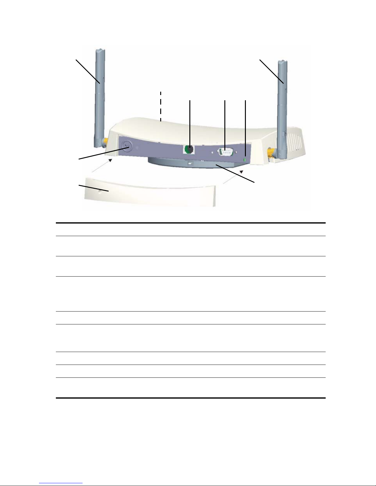
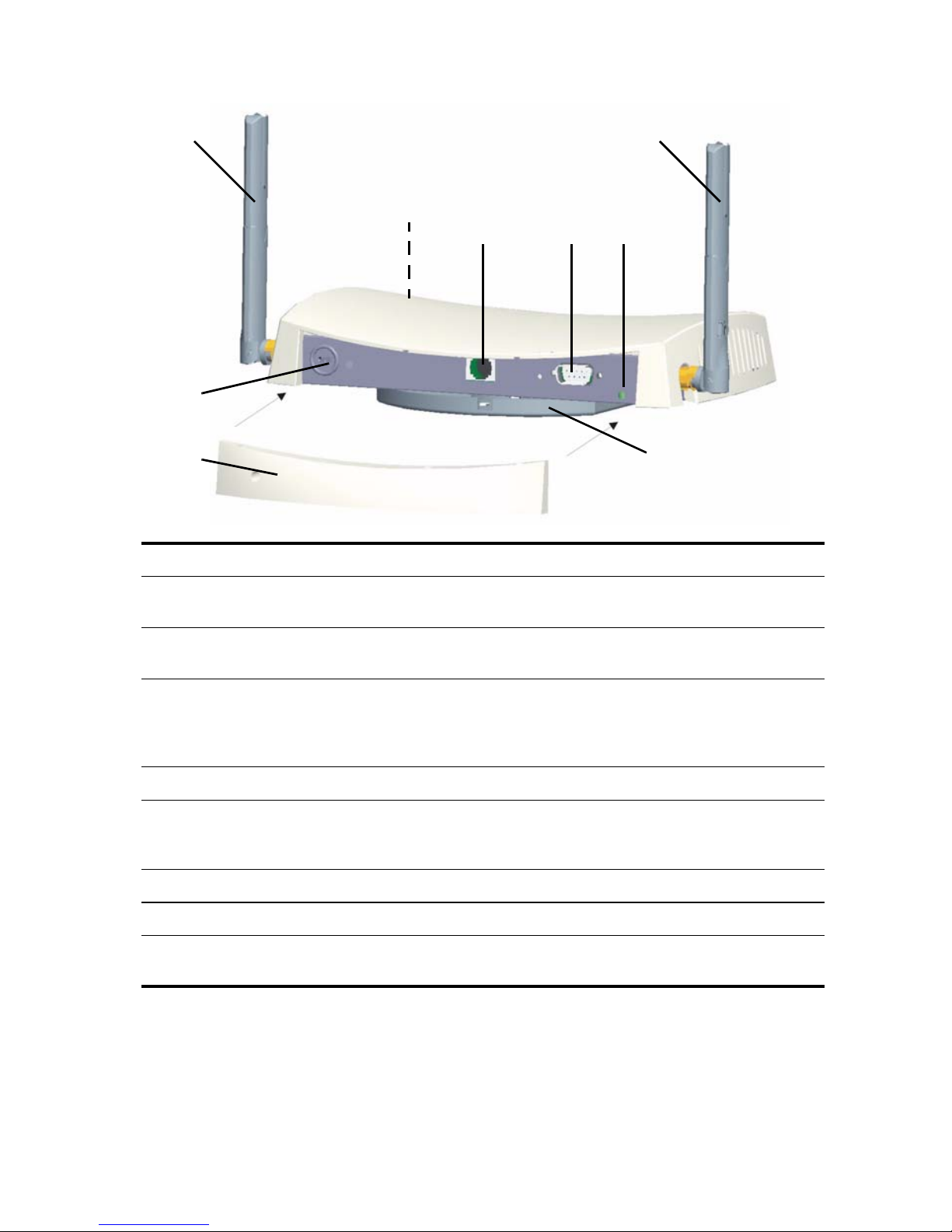
3Com Wireless 8760 Access Point Features
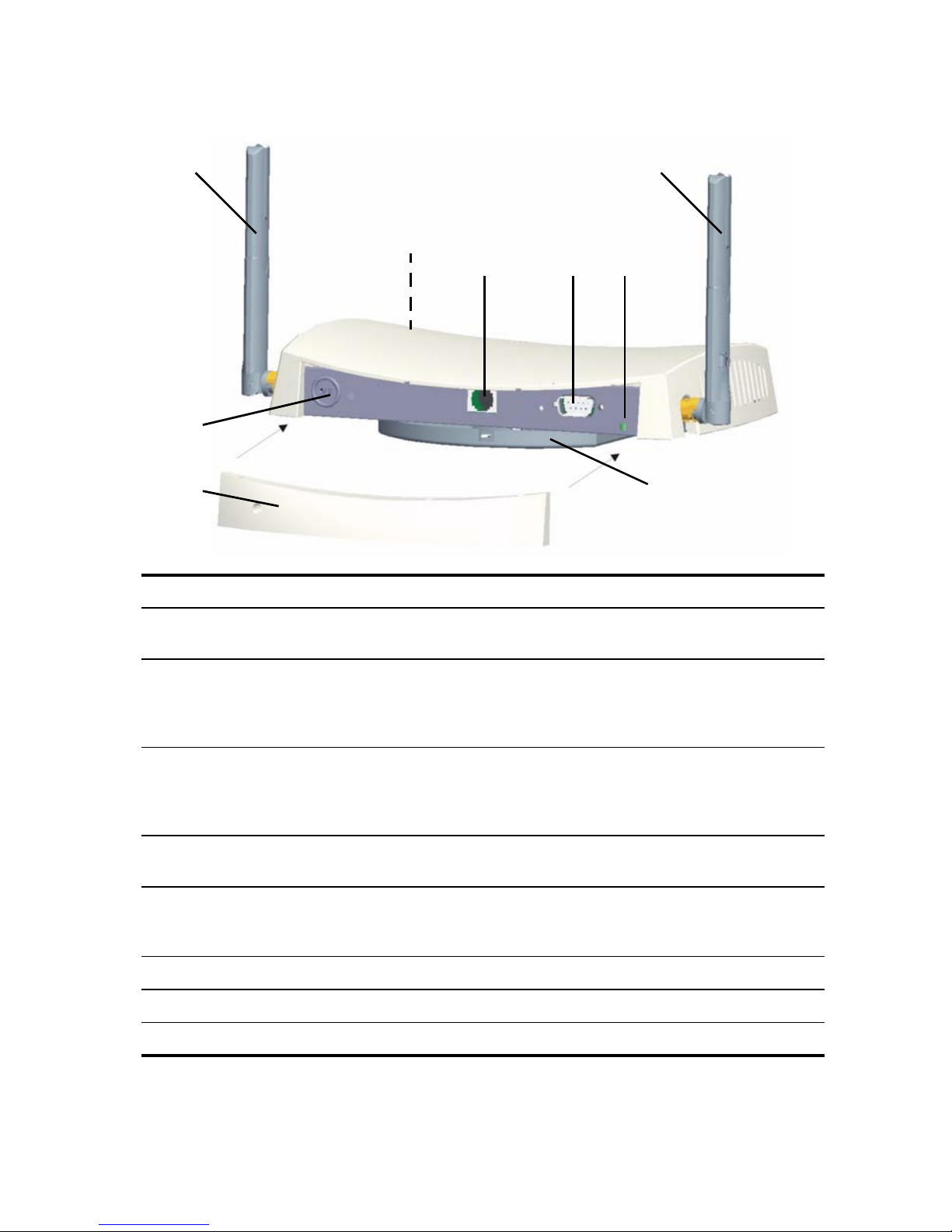
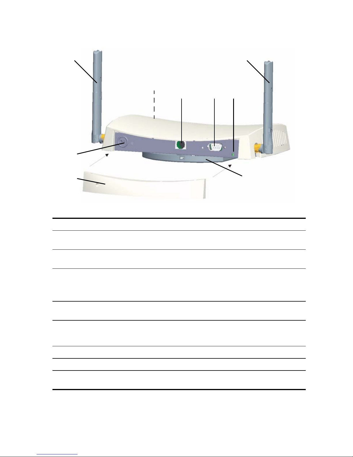
1
1
2
43
5
6
78
Feature Description
1 Antenna
Connectors
2 LEDs The LEDs indicate power and activity. See “Checking the LED
3 Ethernet Port The Ethernet port provides a 10/100BASE-TX Ethernet connection to a
4 Serial Port Provides a serial interface to the Access Point for diagnostic use.
5 Reset Button To restore factory settings, press the reset button during power-up by
6 Kensington lock connector
7 Detachable rear-panel cover
8 Mounting Bracket The mounting bracket comes attached to the Access Point and allows
Two RSMA type antenna connectors allow you to connect antennas
that operate in 2.4
Indicators” on page 8 for details.
3Com switch. Use a suitable Category 5 cable with straight-through
signaling and standard RJ-45 connectors to connect your Access
to the switch on the network.
inserting a pointed object into the reset hole on the back of the
Access
Point and holding for five seconds.
the unit to be mounted on a wall or ceiling.
GHz and 5.0 GHz bands.
Point
2
Page 5

Safety Information
This equipment must be installed in compliance with local and national building codes, regulatory
restrictions, and FCC rules. For the safety of people and equipment, only professional network
personnel should install the Access
WARNING: Warnings contain directions that you must follow for your personal safety.
Follow all directions carefully.
You must read the following safety information carefully before you install or remove the
unit.
WARNING: Exceptional care must be taken during installation and removal of the unit.
WARNING: The socket outlet must be near to the unit and easily accessible. You can
only remove power from the unit by disconnecting the power cord from the outlet.
WARNING: This unit operates under SELV (Safety Extra Low Voltage) conditions
according to IEC
to which it is connected also operates under SELV conditions.
WARNING: There are no user-replaceable fuses or user-serviceable parts inside the
unit. If you have a physical problem with the unit that cannot be solved with problem
solving actions in this guide, contact your supplier.
950 / IEC 60950. The conditions are only maintained if the equipment
Point.
WARNING: Disconnect the power adapter before moving the unit.
WARNING: RJ-45 ports. These are shielded RJ-45 data sockets. They cannot be used
as standard traditional telephone sockets, or to connect the unit to a traditional PBX or
public telephone network. Only connect RJ-45 data connectors, network telephony
systems, or network telephones to these sockets.
Either shielded or unshielded data cables with shielded or unshielded jacks can be
connected to these data sockets.
WARNING: To comply with FCC radio frequency (RF) exposure limits, a minimum
body-to-antenna distance of 20 cm (8 in.) must be maintained when the Access
operational.
Point is
Approved Channels
Use of this product is only authorized for the channels approved by each country. For proper
installation, select your country from the country selection list.
To conform to FCC and other country restrictions your product may be limited in the channels that
are available. If other channels are permitted in your country please visit the 3Com web site for the
latest software version.
www.3Com.com
3
Page 6

Informacje na temat bezpieczeñstwa
Urządzenie musi być zamontowane zgodnie z lokalnymi i krajowymi normami, ustawami
i przepisami. W celu zagwarantowania bezpieczeństwa osób i urządzeń, instalację Punktu
dostępowęgo może przeprowadzać wyłącznie wyszkolony fachowiec ds. sieci.
OSTRZEŻENIE: Ostrzeżenia zawierają wskazówki, których należy przestrzegać
w celu zagwarantowania bezpieczeństwa osobistego. Do tych zaleceń należy
stosować się dokładnie.
Przed przystąpieniem do montażu lub demontażu urządzenia należy dokładnie przeczytać
następujące informacje dotyczące bezpieczeństwa.
OSTRZEŻENIE: Podczas montażu lub demontażu urządzenia należy pracować
z wyjątkową uwagą.
OSTRZEŻENIE: Gniazdo sieciowe powinno znajdować się w pobliżu urządzenia
i być łatwo dostępne. Z urządzenia można odciąć zasilanie wyłącznie poprzez
wyjęcie kabla zasilającego z gniazda.
OSTRZEŻENIE: Urządzenie działa w warunkach SELV (obwód bezpiecznego
niskiego napięcia) zgodnie z normą IEC
zagwarantowane wyłącznie wtedy, gdy sprzęt, do którego podłączone jest
urządzenie, również pracuje w obwodzie SELV.
OSTRZEŻENIE: Wewnątrz urządzenia nie znajdują się wymienne bezpieczniki lub
części, które mogłyby być oddane do naprawy. W przypadku wystąpienia problemu,
którego nie można rozwiązać za pomocą wskazówek podanych w tej instrukcji
obsługi, prosimy o kontakt z dostawcą produktu.
950 / IEC 60950. Warunki te są jednak
OSTRZEŻENIE: Przed przeniesieniem urządzenia należy odłączyć zasilacz.
OSTRZEŻENIE: Porty RJ-45. Są to ekranowane gniazda RJ-45 do danych. Nie są
przeznaczone do użycia jako standardowe gniazda telefoniczne lub do podłączenia
urządzenia do PBX lub publicznej sieci telefonicznej. Do tych gniazd wolno
podłączać wyłącznie wtyki RJ-45 danych, systemów telefonii sieciowej lub telefonów
sieciowych.
Do tych gniazd można podłączać kable danych ekranowane lub nieekranowane
z ekranowanymi lub nieekranowanymi wtykami.
OSTRZEŻENIE: W związku w ograniczeniami częstotliwości radiowej (RF),
minimalna odległość między ciałem a anteną wynosząca 20 cm (8 cali) musi być
zachowana w przypadku stosowania Punkt dostępowy.
4
Page 7

1. Unpacking the Access Point
Make sure that you have the following items, which are included with the Access Point:
• One 3Com Wireless 8760 Dual-radio 11a/b/g PoE Access Point
• Two external dual-band antennas (2.4 GHz and 5.0 GHz)
• One PoE (Power over Ethernet) injector
• One Ethernet cable
• Mounting bracket (attached to the Access Point)
• Four adhesive rubber feet (used for a flat-surface installation).
• One CD-ROM containing the Setup Wizard software, the User’s Manual, and a copy of this
Quick Start Guide.
• One Warranty Flyer
2. Preparing for Installation
It is advisable to connect and check the Ethernet cable and LEDs before installing the Access Point
in a hard-to-reach location. Additionally, observe the following items before mounting or
connecting the Access
Feature Description
Point:
Switch Port To connect your wireless network to your wired network, you need a
hub or switch connected to the Access
Cabling Make sure that standard Ethernet cable with straight-through
signaling is installed at the site before you install the Access
Make sure that the cable is highly flexible and that there is no extra
covering on the RJ-45 connector that could prevent the cable from
being routed through the mounting bracket.
Power Requirement Power is supplied using an 802.3af Power Over Ethernet (PoE)
compliant device. A PoE injector is included.
MAC Address Record the access point MAC address in a safe place before the
Access
The MAC address is printed on the back of the Access Point.
Point is installed in a hard-to-reach location.
Point.
Point.
3. Attaching the Antennas
Carefully unpack the standard detachable antennas that came with your Access Point. Thread
each antenna onto an antenna connector on the Access
network startup, you may need to adjust the antennas to fine-tune coverage in your area.
For best results, adjust the antennas so they are perpendicular to the floor and ceiling.
Point and hand-tighten them. After
CAUTION: Do not handle the antenna tips, especially after they are connected to the
Access
Point. This could lead to electrostatic discharge (ESD), which could damage the
equipment.
5
Page 8
4. Mounting the Access Point
The access point can be mounted on the following types of surfaces:
• Wall, ceiling, or electrical box (NEMA enclosure)
• Tabletop
Wall, Ceiling, or Electrical Box Mounting
Use the mounting bracket that comes with your Access Point to install it on a wall, ceiling, or
electrical box.
To wall-mount the Access Point:
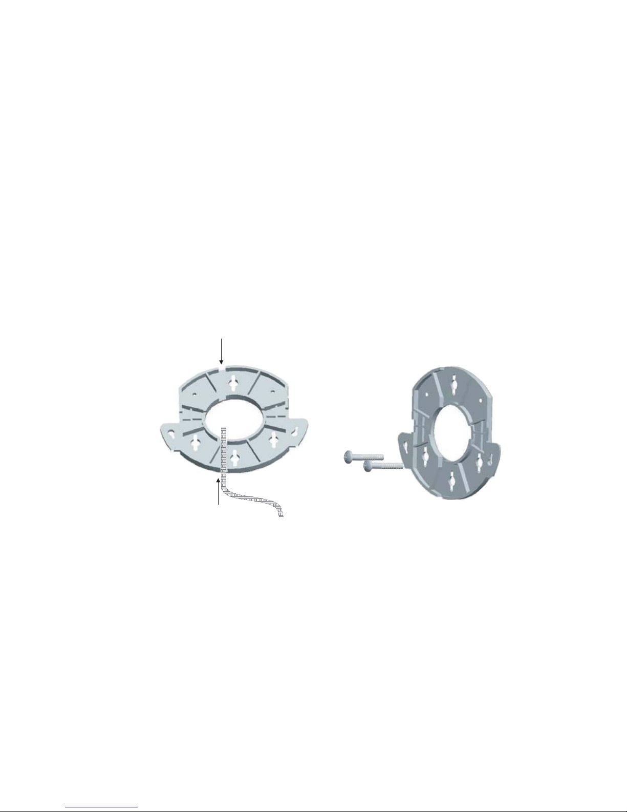
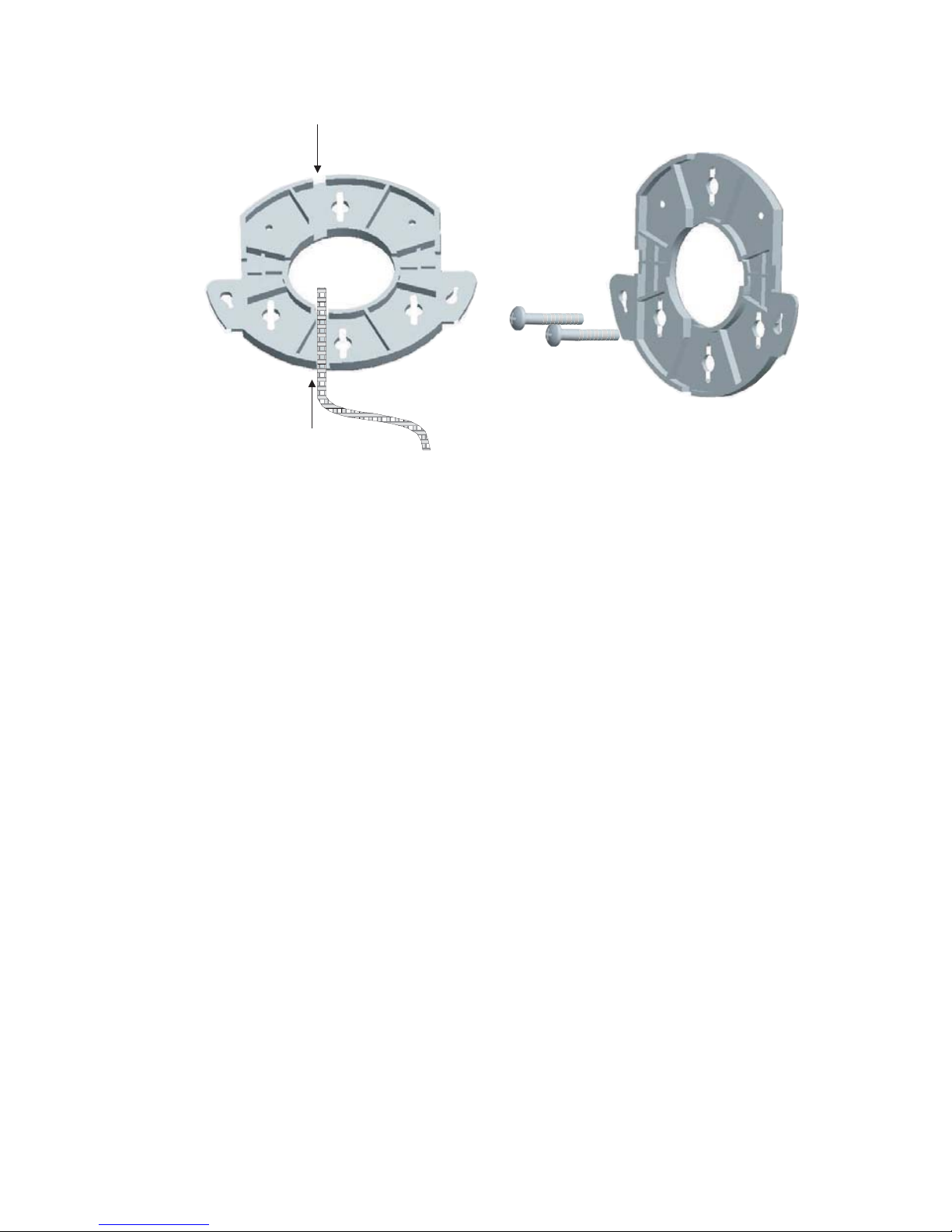
1 Route Ethernet cable through the opening in the cradle.
2 Screw the mounting bracket to a wall, ceiling, or electrical box (NEMA enclosure):
• If mounting to a solid surface wall or ceiling, use the two sheet metal screws.
• If mounting to drywall, use the two sheet metal screws and two wall anchors.
• If mounting to an electrical box (NEMA enclosure), use the two threaded screws.
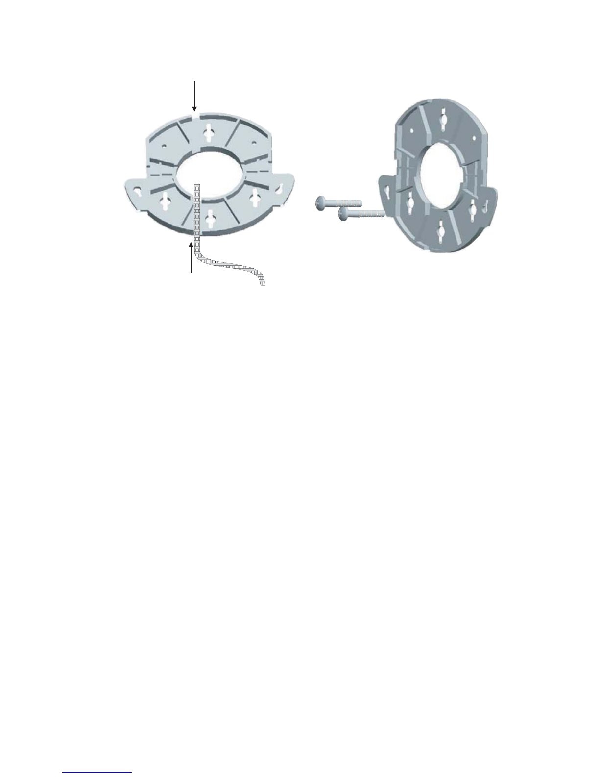
The figures below show a cable being routed through the large opening in the cradle and
then the cradle being mounted to a wall.
3 Connect the Ethernet cable (for power and network connection) to the port on the rear of
the Access
Point.
4 Twist the Access Point onto the mounting bracket.
Tabletop Mounting
To install the Access Point on a flat surface such as a table or desktop:
1 Remove the backing from the four rubber feet and attach them on the bottom of the
Access
Point.
2 Place the Access Point on the table.
3 Connect the Ethernet cable (for power and network connection) to the port on the rear of
the Access
Point.
Wall-mounting the cradleRouting a cable
6
Page 9
5. Connecting Power
3CRWX120695A
Wir
el
ess LAN Swit
ch WX1200
TO ACCESS POINT
TO HUB/SWITCH
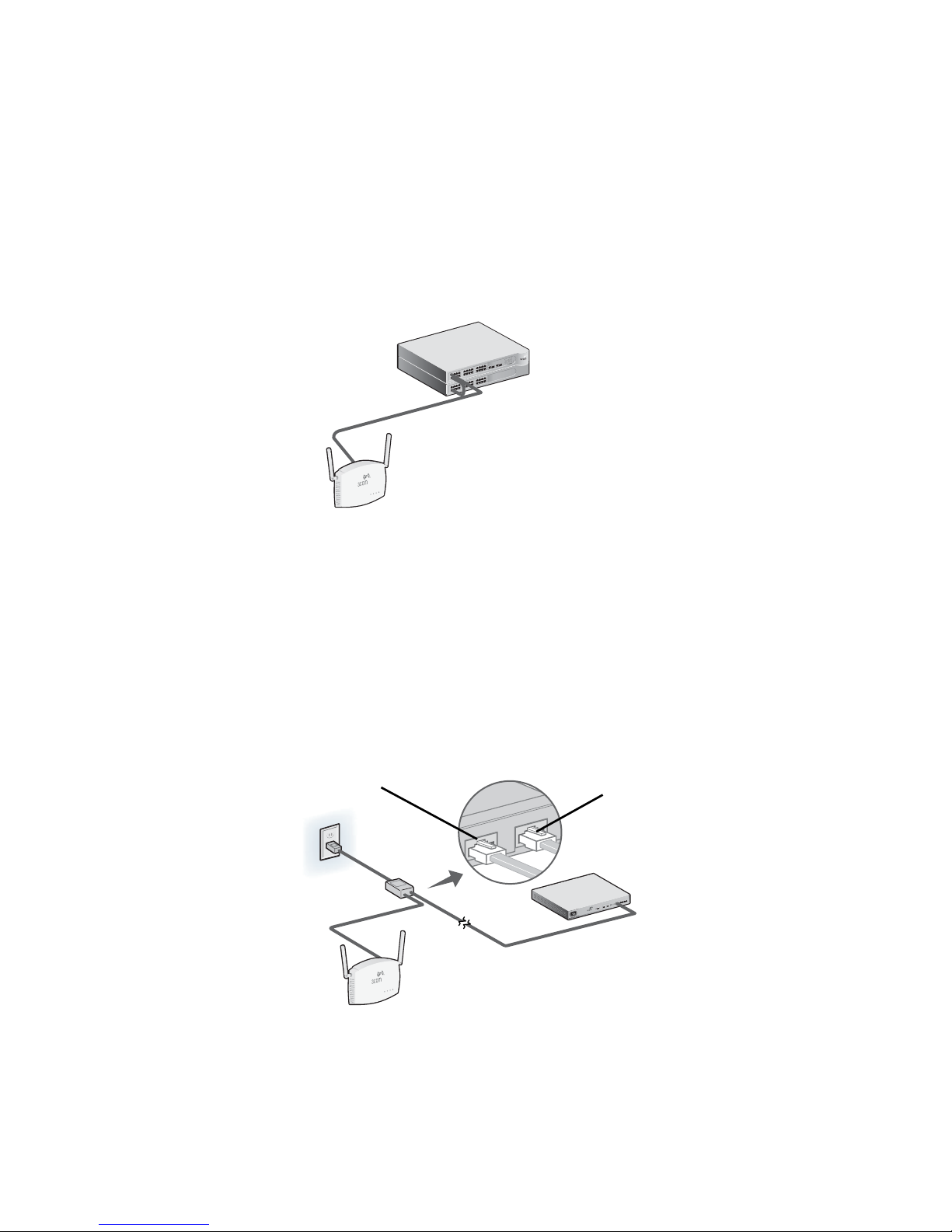
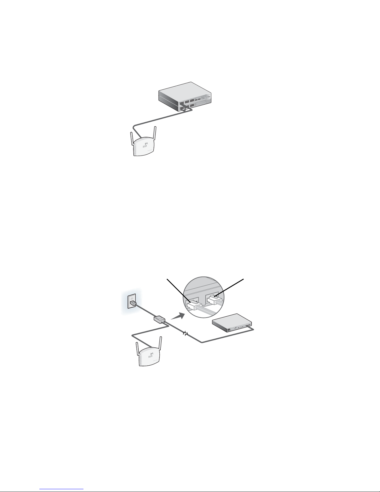
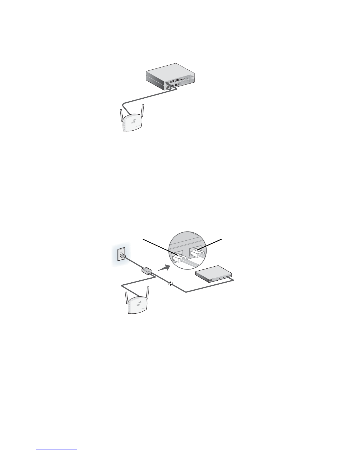
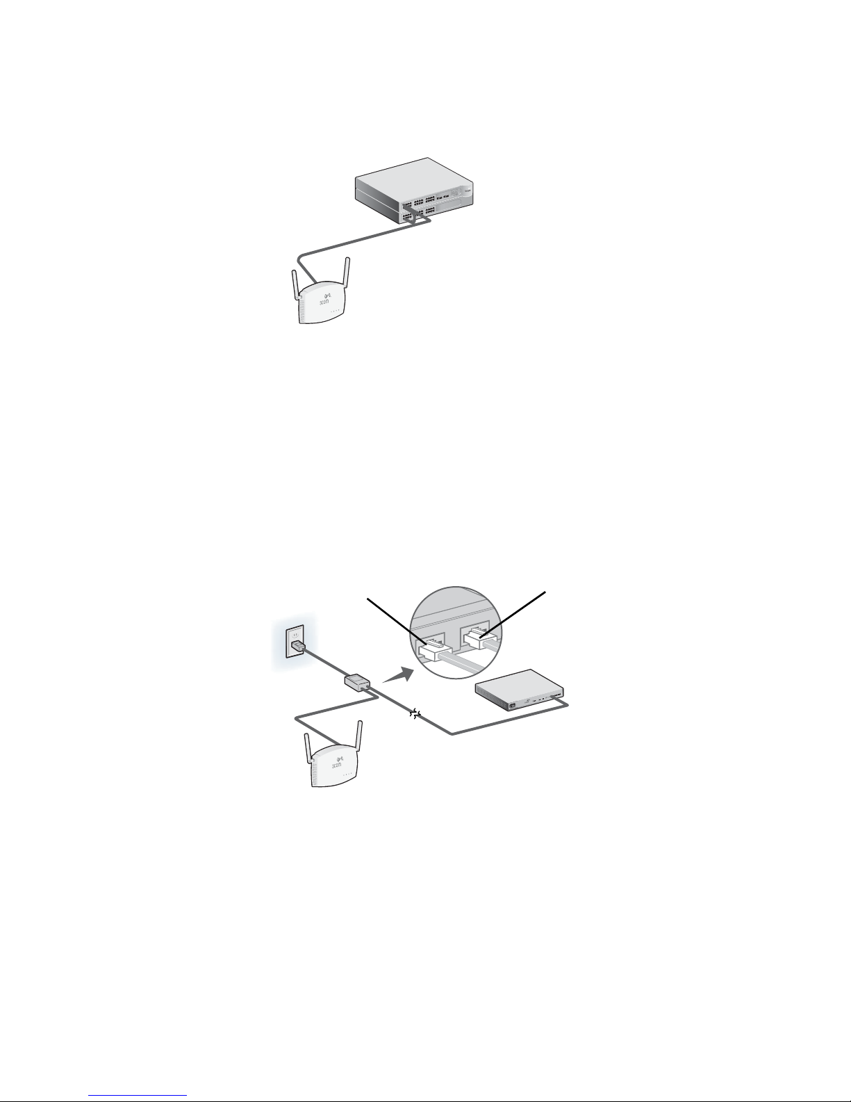
The Access Point can be powered by the following methods:
• By Power Over Ethernet (PoE) supplied over the LAN by a 802.3af PoE compliant device such
as a switch or hub.
• By PoE supplied by the PoE injector included with the Access Point.
Power Over Ethernet (PoE) from the LAN
To power the Access Point using PoE provided by a switch or other 802.3af compliant device,
simply plug the network cable from the device into the Access
Access Point
Point’s Ethernet port.
PoE Switch/Hub
Power Over Ethernet from a PoE Injector
To power the Access Point using the 3Com PoE Injector (included with the unit), do the following:
1 Connect the LAN cable from the switch or hub to the Hub/Switch port on the 3Com PoE
Injector (included with Access
2 Next connect a LAN cable from the Ethernet port on the Access Point to the other port on
the PoE injector.
3 Plug the PoE Injector into a properly grounded electric outlet.
Access Point
Point).
To Access Point
To Switch/Hub
Switch/Hub
ch WX1200
LAN Swit
ess
el
Wir
3CRWX120695A
(non-PoE)
7
Page 10
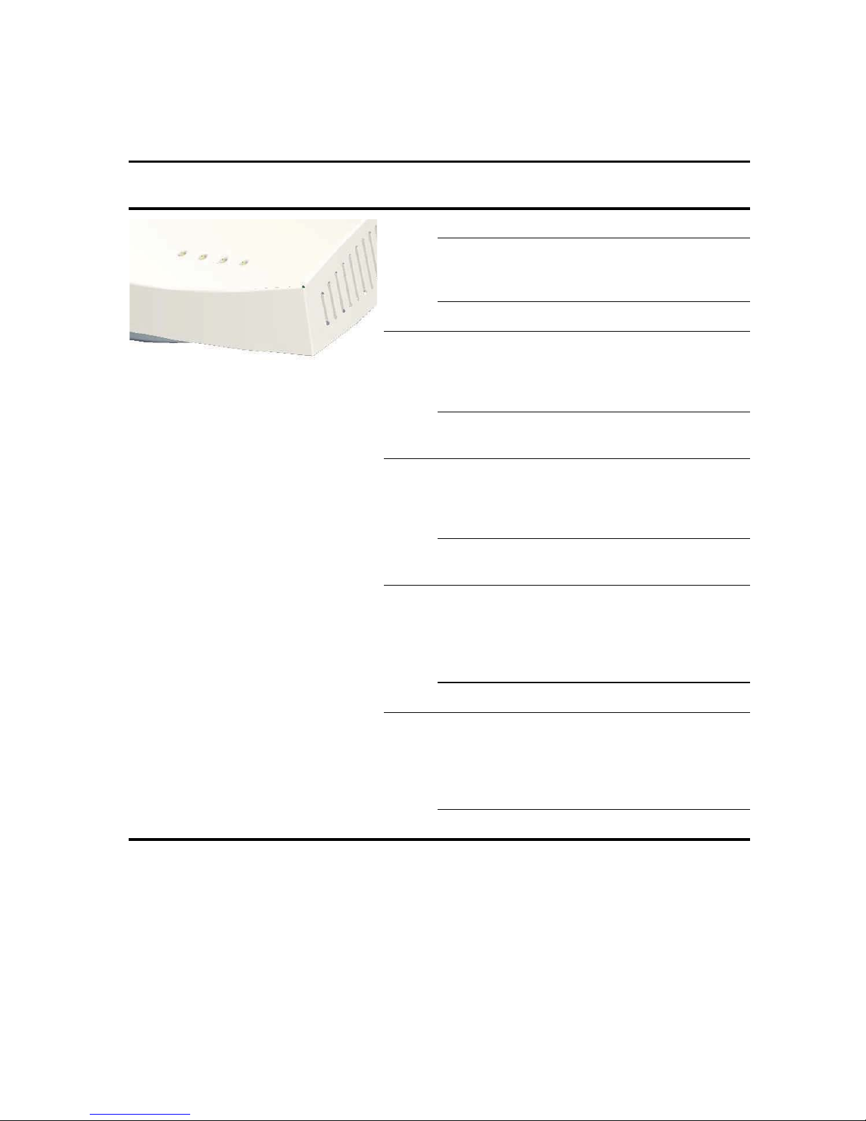
6. Checking the LED Indicators
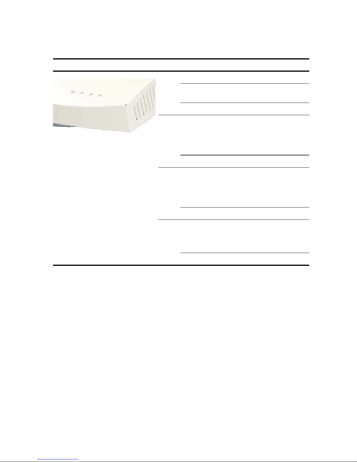
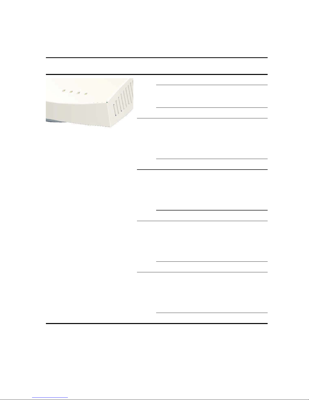
When the Access Point is connected to power, LEDs indicate activity as follows:
LED Color Indicates
Power Green Power On
Amber Flashing indicates a hardware failure,
or the system is booting.
Off Power Off
11a Green Indicates that 802.11a 5.0 GHz
wireless networking is enabled. If the
LED is flashing, the wireless link is OK
and data is being transmitted or
received.
Off The radio is off
11b/g Green Indicates that 802.11g 2.4 GHz
wireless networking is enabled. If the
LED is flashing, the wireless link is OK
and data is being transmitted or
received.
Off The radio is off
LAN Green Indicates a 10/100Base-T network is
detected at the Ethernet port. If the
LED is flashing, the link is OK and
data is being transmitted or received.
Off No link
7. Installing Software
The following applications and documents are included on the 3Com CD-ROM:
• Wireless Infrastructure Device Manager
• User manual
• This Quick Start Guide
You need to install the Wireless Infrastructure Device Manager software (WIDMan) on your
computer to discover and configure the Access
1 Turn on your computer.
2 Insert the 3Com Installation CD into the CD-ROM drive.
The CD menu appears. If it does not appear, you can start the Setup menu from the
Windows Start menu. For example: Start > Run > d:setup.exe.
Point.
3 On the menu, click Utilities.
4 On the next screen, double-click 3Com Wireless Infrastructure Device Manager and then
click Install to install it.
8
Page 11

5 Follow the instructions on the screens to complete the installation. Reboot the computer if
prompted to do so.
6 Launch the tool from the Windows Start menu: select Start > Programs > 3Com Wireless
> Wireless Infrastructure Device Manager.
8. Connecting to the Access Point
You can connect to the Access Point on networks that have a DHCP server, and on networks that
do not have a DHCP server. To connect you must find the Access
Finding the IP Address on Networks with a DHCP Server
If your network has a DHCP server, an IP address is automatically assigned to the Access Point. The
Access
Point takes between one and two minutes to detect a DHCP server on the network. Use
WIDMan to locate the Access
Next enter that IP address into a web browser on a computer on the same subnet to view the
Access
Point’s system status or change its configuration.
Point on the network and view its IP address (see “Using WIDMan”).
Finding the IP Address on Networks without a DHCP Server
If your network does not have a DHCP server, the Access Point uses a default factory-assigned IP
address (169.254.2.1).
Point’s IP address.
Using WIDMan
3Com WIDMan (Wireless Infrastructure Device Manager) software lets you discover and configure
your Access
Point. Follow these steps to use WIDMan to determine the Access Point’s IP address.
1 Connect your computer to the Access Point either directly, or over the network.
2 Launch WIDMan from the Windows Start menu: Start > Programs > 3Com Wireless >
Wireless Infrastructure Device Manager.
When your Access Point is detected it will be shown in the Wireless Network Tree screen.
3 Click to select your Access Point and then click the Properties button.
4 Make a note of your Access Point’s IP Address.
9. Configuring the Access Point
To configure the Access Point follows these steps:
1 Connect to the Access Point and find its IP Address as described in “Connecting to the
Access Point”.
2 Launch your computer’s web browser. In the address bar, enter your Access Point’s IP
Address and press Enter.
3 At the Access Point Login Screen, type the user name and password and click Log On.
The default username and password are case-sensitive:
• Username: admin
• Password: password
9
Page 12

4 If this is the first time you are logging onto the Access Point you will be prompted to select
the country in which you will be using the device. Choose your country from the menu and
then click Apply.
5 Next use the Setup Wizard to configure your Access Point. Click Setup Wizard in the menu
on the left side of the screen.
6 Follow the prompts on the screen. Use the Next and Back buttons to move through the
screens. Click Finish when you are done.
For complete details on using the Wireless Infrastructure Device Manager and configuring your
Access
Point, refer to the 3Com Wireless 8760 Dual-radio 11a/b/g PoE Access Point User Guide
included on the product CD. Updates to the user manual may be found on our website:
http://www.3Com.com.
10.Troubleshooting
For troubleshooting information please refer to your User's Guide or visit 3Com’s World Wide
Web site:
http://www.3Com.com.
10
Page 13

Guide de mise en route
3Com Wireless 8760
11a/b/g PoE Access Point
3CRWE876075 / WL-546
Le point d’accès sans fil 3Com Wireless 8760 11a/b/g PoE Access Point associe hautes
performances, interopérabilité et simplicité d’utilisation pour englober des réseaux câblés isolés
dans un seul et même réseau local sans fil. Point d'accès sans fil 8760 propose également de
puissantes fonctions de sécurité, et répond aux normes de réseau standard comme 802.11a et
802.11g.
Le présent guide de mise en route indique la procédure à suivre pour installer et configurer votre
point d’accès 3Com Wireless
de clarté, le point d’accès Wireless
8760 11a/b/g PoE Access Point (3CRWE876075 / WL-546). Par souci
8760 Access Point est désigné par point d’accès dans ce guide.
À propos de ce guide
Le présent guide décrit les étapes d’installation du point d’accès. Il comprend les sections suivantes :
• Présentation du point d’accès 3Com Wireless 8760
• Informations relatives à la sécurité
• Étape 1 : Contenu du coffret
• Étape 2 : Préparation de l’installation
• Étape 3 : Raccordement des antennes
• Étape 4 : Fixation du point d’accès
• Étape 5 : Mise sous tension
• Étape 6 : Vérification des voyants lumineux
• Étape 7 : Installation du logiciel
• Étape 8 : Connexion au point d’accès
• Étape 9 : Configuration du point d’accès
• Dépannage
Page 14
Présentation du point d’accès 3Com
Wireless
1
8760
1
2
43
5
6
78
Fonction Description
1 Connecteurs
d’antenne
2 Voyants Les voyants lumineux s’allument lorsque le point d’accès est sous
3 Port Ethernet Ce port permet d’établir une connexion Ethernet 10/100BASE-TX à un
4 Port série Ce port fournit une interface série au point d’accès à des fins de
5 Bouton de
réinitialisation
6 Connecteur de verrou Kensington
7 Capot du panneau arrière amovible
8 Support de fixation Ce support permet de fixer le point d’accès sur un mur ou au plafond.
Ces deux connecteurs RSMA permettent de brancher des antennes
fonctionnant sur les bandes de fréquences 2,4
tension et lorsque des activités sont en cours. Pour plus de détails, voir
la section
page 18.
commutateur 3Com. Utilisez un câble droit de catégorie 5 et des
connecteurs RJ45 standard pour relier le point
commutateur du réseau.
diagnostic.
Pour rétablir les paramètres par défaut, exercez une pression pendant
deux à cinq secondes sur ce bouton, placé à l’arrière du point
à l’aide d’un objet pointu.
Voir la section « Vérification des voyants lumineux »,
GHz et 5,0 GHz
d’accès au
d’accès,
12
Page 15
Informations relatives à la sécurité
Cet équipement doit être installé conformément aux normes de construction locales et nationales,
aux restrictions réglementaires et au règlement du FCC. Pour garantir la sécurité des personnes et
des équipements, seul le personnel chargé de la gestion du réseau est autorisé à procéder à
l’installation du point
AVERTISSEMENT : Ces avertissements contiennent des instructions que vous devez
impérativement suivre pour votre propre sécurité. Respectez strictement toutes les
instructions.
Lisez attentivement les informations de sécurité suivantes avant d’installer ou de désinstaller
l’unité.
AVERTISSEMENT : Faites preuve de la plus grande attention lors des opérations
d’installation et de désinstallation de l’unité.
AVERTISSEMENT : La prise de courant à laquelle vous branchez l’unité doit être facile
d’accès. Le seul moyen de mettre l’unité hors tension est de débrancher le cordon
d’alimentation de la prise.
AVERTISSEMENT : Cette unité fonctionne en très basse tension, et respecte les
normes IEC
normes sont respectées uniquement si l’équipement auquel elle est connectée
fonctionne également en très basse tension.
d’accès.
950 / IEC 60950 de la Commission électrotechnique internationale. Ces
AVERTISSEMENT : L’unité ne contient ni fusibles, ni pièces nécessitant un entretien
particulier. Si vous rencontrez un problème que vous ne parvenez pas à résoudre en
suivant les mesures correctives proposées dans ce guide, contactez votre fournisseur.
AVERTISSEMENT : Débranchez le bloc d’alimentation de la prise secteur avant de
déplacer l’unité.
AVERTISSEMENT : Ports RJ45. Il s’agit de prises RJ45 blindées pour transmission de
données. Ces prises ne peuvent en aucun cas être utilisées comme prises de téléphone
standard, ou pour connecter l’unité à un autocommutateur privé classique ou un
réseau téléphonique public. Branchez uniquement des connecteurs RJ-45 pour
transmission de données, des systèmes de téléphonie en réseau ou des téléphones en
réseau à ces prises.
Il est possible de brancher des câbles de données blindés ou non blindés équipés de
prises jack blindées ou non blindées à ces prises de transmission de données.
AVERTISSEMENT : Conformément aux dispositions relatives à l’exposition aux
radiofréquences du règlement du FCC, il convient de se tenir à une distance minimale
de 20 cm de l’antenne lorsque le point
d’accès est en fonctionnement.
Canaux approuvés
Ce produit peut être utilisé uniquement sur une plage limitée de canaux, propre à chaque pays.
Pour assurer une installation correcte, sélectionnez votre pays dans la liste.
Conformément aux dispositions relatives à l’utilisation des canaux du règlement FCC, seuls les
canaux de la plage 1-11 sont disponibles par défaut. Si l’utilisation des canaux de la plage 1-13 est
autorisée dans votre pays, visitez le site Web de 3Com pour obtenir la dernière version du logiciel.
www.3Com.com
13
Page 16

1. Contenu du coffret
Vérifiez que vous disposez des éléments suivants, fournis avec le point d’accès :
• Point d’accès 3Com Wireless 8760 11a/b/g PoE
• 2 antennes externes à deux bandes de fréquences (2,4 GHz et 5,0 GHz)
• Injecteur PoE (Power over Ethernet)
• Câble Ethernet
• Matériel pour la fixation murale :
• Support de fixation (assemblé au point d’accès)
• 2 vis à tôle
• 2 boulons
• 2 chevilles
• 4 pieds adhésifs en caoutchouc (pour une installation à l’horizontale sur une surface plane)
• CD-ROM contenant l’Assistant d’installation, le Manuel de l’utilisateur et une copie du
présent Guide de mise en route.
• Certificat de garantie
2. Préparation de l’installation
Il est recommandé de mettre l’équipement sous tension, de vérifier le branchement du câble
Ethernet et de s’assurer que les voyants s’allument avant d’installer le point
emplacement difficile d’accès. Vérifiez également les points suivants avant de fixer ou de
connecter le point
d’accès :
d’accès à un
Fonction Description
Port du commutateur Pour relier votre réseau sans fil à votre réseau câblé, vous devez
connecter un concentrateur ou un commutateur au point
Câblage Vérifiez que le site est équipé d’un câble droit Ethernet standard avant
d’installer le point
Assurez-vous qu’il s’agit d’un câble très souple et que le connecteur
RJ45 passe sans encombre dans l’encoche du support de fixation.
Alimentation électrique L’alimentation électrique par câble Ethernet (PoE) est assurée par un
dispositif répondant à la norme 802.3af. Un injecteur PoE est fourni.
Adresse MAC Notez l’adresse MAC pour référence ultérieure avant d’installer le
point
d’accès à un emplacement difficile d’accès.
Cette adresse MAC est imprimée à l’arrière du point d’accès. Des
étiquettes portant l’adresse MAC sont fournies avec le point
d’accès.
d’accès.
d’accès.
14
Page 17

3. Raccordement des antennes
Déballez soigneusement les antennes amovibles standard fournies avec le point d’accès. Insérez
les deux antennes dans les connecteurs du point
réseau, il vous faut régler les antennes pour optimiser la zone de couverture.
Pour des résultats satisfaisants, orientez les antennes de façon qu’elles soient perpendiculaires au
sol et au plafond.
ATTENTION : Veillez à ne pas toucher aux extrémités des antennes, particulièrement
lorsque celles-ci sont raccordées au point
décharge électrostatique (ESD), ce qui peut endommager l’équipement.
d’accès et redressez-les. Après le démarrage du
d’accès. Cela peut en effet entraîner une
4. Fixation du point d’accès
Vous pouvez installer le point d’accès à plusieurs emplacements :
• Mur, plafond ou armoire électrique normalisée
• Table
Fixation au mur, au plafond ou dans une armoire
électrique
Utilisez le support de fixation fourni avec le point d’accès pour l’installer sur un mur, au plafond ou
dans une armoire électrique. Pour une sécurité optimale, utilisez la tige de verrouillage et un
cadenas (non fourni) pour verrouiller le point
murale.
Pour fixer le point d’accès au mur :
d’accès au socle dans le cas d’une installation
1 Faites passer le câble Ethernet dans la plus grosse encoche du support.
2 Vissez le support au mur, au plafond ou dans l’armoire électrique normalisée.
• Pour une fixation sur un mur plein ou au plafond, utilisez les deux vis à tôle.
• Pour une fixation sur une cloison, utilisez les deux vis à tôle et les deux chevilles.
• Pour une fixation dans une armoire électrique normalisée, utilisez les deux boulons.
15
Page 18
Les schémas ci-dessous illustrent comment passer le câble dans la grosse encoche et
comment fixer le support au mur.
3 Insérez le câble Ethernet (alimentation et connexion au réseau) dans le port placé à l’avant du
point
d’accès.
4 Assemblez le point d'accès au support de fixation..
Fixation sur table
Pour installer le point d’accès sur une surface plane, comme une table ou un bureau :
1 Décollez la bande de protection des quatre pieds en caoutchouc et collez-les sur le support
de fixation assemblé au point
d’accès.
2 Placez le point d’accès sur la table.
3 Insérez le câble Ethernet (alimentation et connexion au réseau) dans le port placé à l’avant du
point
d’accès.
5. Mise sous tension
Le point d’accès peut être alimenté par les méthodes suivantes :
• Alimentation électrique par câble Ethernet assurée à partir du réseau local par le biais d’un
dispositif PoE répondant à la norme 802.3af, comme un commutateur ou un concentrateur.
• Alimentation électrique par câble Ethernet assurée par le biais de l’injecteur PoE fourni avec
le point
d’accès.
16
Page 19
Alimentation électrique par câble Ethernet depuis
3CRWX120695A
Wir
el
ess LAN Swit
ch WX1200
TO ACCESS POINT
TO HUB/SWITCH
le réseau local
Pour alimenter le point d’accès par le biais d’un commutateur ou d’un autre dispositif répondant à
la norme 802.3af, il suffit de brancher le câble réseau du dispositif dans le port Ethernet du
point
d’accès.
Commutateur/Concentrateur PoE
Point d’accès
Alimentation électrique par câble Ethernet depuis
un injecteur PoE
Pour alimenter le point d’accès à l’aide de l’injecteur PoE 3Com (fourni), procédez comme suit :
1 Insérez le câble réseau connecté au commutateur ou au concentrateur dans le port
Concentrateur/Commutateur de l’injecteur PoE 3Com (fourni avec le point
d’accès).
2 Insérez ensuite le câble réseau connecté au port Ethernet du point d’accès dans l’autre port
de l’injecteur PoE.
3 Branchez l’injecteur PoE à une prise de courant avec mise à la terre.
Vers le point d’accès Vers le commutateur/concentrateur
ch WX1200
ess LAN Swit
Wirel
3CRWX120695A
Commutateur/Concentrateur
Point d’accès
(non PoE)
17
Page 20
6. Vérification des voyants lumineux
Lorsque le point d’accès est sous tension, différents voyants s’allument pour indiquer les activités
en cours, répertoriées ci-dessous :
VoyantCouleur Indication
Marche Vert Sous tension
Orange Lorsque le voyant clignote, cela
indique une défaillance du matériel
ou le démarrage du système.
Éteint Hors tension
11a Vert La connexion 802.11a 5,0 GHz sans
fil est établie. Lorsque le voyant
clignote, des données sont
actuellement transmises ou reçues.
Éteint La transmission radio est
interrompue.
11b/g Vert La connexion 802.11g 2,4 GHz sans
fil est établie. Lorsque le voyant
clignote, des données sont
actuellement transmises ou reçues.
Éteint La transmission radio est
interrompue.
LAN Vert Un réseau 10/100Base-T est détecté
sur le port Ethernet. Lorsque le voyant
clignote, la connexion est établie, et
des données sont actuellement
transmises ou reçues.
Éteint Aucune connexion
10 Vert Un réseau 10Base-T est détecté sur le
port Ethernet. Lorsque le voyant
clignote, la connexion est établie, et
des données sont actuellement
transmises ou reçues.
Éteint Aucune connexion
7. Installation du logiciel
Le CD-ROM 3Com inclut les applications et documents suivants :
• Wireless Infrastructure Device Manager (Gestionnaire de périphériques pour infrastructure
sans fil)
• Manuel de l’utilisateur
• Guide de mise en route
18
Page 21

Vous devez installer le logiciel Wireless Infrastructure Device Manager (WIDMan) sur votre
ordinateur pour détecter et configurer le point
d’accès.
1 Allumez votre ordinateur.
2 Insérez le CD-ROM d’installation 3Com dans le lecteur.
Le menu du CD-ROM apparaît. S’il n’apparaît pas, vous pouvez lancer le menu d’installation
à partir du menu Démarrer de Windows. Par exemple : Démarrer > Exécuter >
d:setup.exe.
3 Dans le menu, cliquez sur Utilities (Utilitaires).
4 Dans l’écran suivant, double-cliquez sur 3Com Wireless Infrastructure Device Manager,
puis cliquez sur Install pour l’installer.
5 Suivez les instructions à l’écran pour procéder à l’installation. Redémarrez votre ordinateur si
vous y êtes invité.
6 Lancez l’outil à partir du menu Démarrer de Windows : sélectionnez Démarrer >
Programmes > 3Com Wireless > Wireless Infrastructure Device Manager.
8. Connexion au point d’accès
Vous pouvez vous connecter au point d’accès sur un réseau équipé ou non d’un serveur DHCP.
Pour procéder à la connexion, vous devez disposer de l’adresse IP du point
d’accès.
Recherche de l’adresse IP sur un réseau équipé
d’un serveur DHCP
Si votre réseau comprend un serveur DHCP, une adresse IP est automatiquement attribuée au
point
d’accès. Il faut une à deux minutes au point d’accès pour détecter la présence d’un serveur
DHCP sur le réseau. Utilisez le logiciel WIDMan pour localiser le point
afficher son adresse IP (voir la section
dans un navigateur Web sur un ordinateur placé dans le même sous-réseau pour afficher l’état
système du point
d’accès ou modifier sa configuration.
“Utilisation de WIDMan”). Entrez ensuite cette adresse IP
d’accès sur le réseau et
Recherche de l’adresse IP sur un réseau sans
serveur DHCP
Si votre réseau ne comprend pas de serveur DHCP, le point d’accès utilise une adresse IP par
défaut (169.254.2.2).
19
Page 22

Utilisation de WIDMan
Le logiciel 3Com WIDMan (Wireless Infrastructure Device Manager) vous permet de détecter et de
configurer le point
point
d’accès à l’aide de WIDMan.
d’accès. Suivez la procédure ci-après pour déterminer l’adresse IP du
1 Connectez votre ordinateur au point d’accès, directement ou par le biais du réseau.
2 Lancez WIDMan à partir du menu Démarrer de Windows : Démarrer > Programmes >
3Com Wireless > Wireless Infrastructure Device Manager.
Lorsque le point d’accès est détecté, il apparaît dans l’écran présentant l’arborescence du
réseau sans fil.
3 Cliquez sur votre point d’accès pour le sélectionner, puis cliquez sur le bouton Properties
(Propriétés).
4 Notez l’adresse IP du point d’accès.
9. Configuration du point d’accès
Pour configurer le point d’accès, suivez la procédure ci-dessous :
1 Connectez-vous au point d’accès et recherchez son adresse IP en suivant la procédure décrite
à la section
“Connexion au point d’accès”.
2 Démarrez le navigateur Web de votre ordinateur. Dans la barre d’adresse, entrez l’adresse IP
de votre point
d’accès et appuyez sur la touche Entrée.
3 Dans l’écran de connexion au point d’accès, tapez le nom d’utilisateur et le mot de passe,
puis cliquez sur Log On.
Le nom d’utilisateur et le mot de passe par défaut respectent la casse :
• Nom d’utilisateur : admin
• Mot de passe : password
4 Lorsque vous vous connectez au point d’accès pour la première fois, vous êtes invité à
sélectionner le pays d’utilisation de l’unité. Choisissez votre pays dans le menu, puis cliquez
sur Apply (Appliquer).
5 Utilisez ensuite l’Assistant d’installation pour configurer le point d’accès. Cliquez sur Setup
Wizard (Assistant d’installation) dans le menu situé à gauche.
6 Suivez les instructions qui s’affichent à l’écran. Cliquez sur le bouton Next ou Back pour
passer à l’écran suivant ou revenir à l’écran précédent. Cliquez sur Finish lorsque vous avez
terminé la configuration.
Pour des informations détaillées sur l’utilisation du logiciel Wireless Infrastructure Device Manager
et la configuration du point
11a/b/g PoE Access Point User Guide inclus sur le CD-ROM du produit. Vous trouverez des mises à
jour du manuel de l’utilisateur sur notre site Web :
http://www.3Com.com.
d’accès, reportez-vous au Manuel de l’utilisateur 3Com Wireless 8760
10.Dépannage
Pour obtenir des informations relatives au dépannage, reportez-vous au manuel de l’utilisateur ou
visitez le site Web de 3Com, à l’adresse :
http://www.3Com.com.
20
Page 23

Guida introduttiva
Access Point Wireless 8760
11a/b/g PoE 3Com
3CRWE876075 / WL-546
L'Access Point Wireless 8760 11a/b/g PoE 3Com unisce prestazioni elevate, interoperabilità e
facilità di utilizzo per unire reti cablate isolate in un'unica rete locale wireless (WLAN)
interconnessa. L'Access Point Wireless
basate su standard e supporta standard di rete wireless inclusi i protocolli 802.11a e 802.11g.
Questa Guida introduttiva descrive le operazioni di base necessarie per installare e configurare
l'Access Point Wireless
guida, l'Access Point Wireless
brevità.
8760 11a/b/g PoE 3Com (3CRWE876075 / WL-546). Nel corso di questa
8760 verrà indicato semplicemente come "access point" per
8760 comprende inoltre potenti funzionalità di protezione
Informazioni su questa guida
Questa guida descrive la procedura di installazione di base dell'access point. Saranno trattati i
seguenti argomenti:
• Caratteristiche dell'Access Point Wireless 8760 3Com
• Informazioni sulla sicurezza
• Passaggio 1: Apertura della confezione dell'access point
• Passaggio 2: Preparazione per l'installazione
• Passaggio 3: Collegamento delle antenne
• Passaggio 4: Montaggio dell'access point
• Passaggio 5: Collegamento dell'alimentazione
• Passaggio 6: Controllo degli indicatori LED
• Passaggio 7: Installazione del software
• Passaggio 8: Connessione all' access point
• Passaggio 9: Configurazione dell' access point
• Risoluzione dei problemi
Page 24
Caratteristiche dell'Access Point Wireless 8760 3Com
1
1
2
43
5
6
78
Caratteristica Descrizione
1 Connettori antenna Due connettori di antenna tipo RSMA consentono di collegare
antenne operanti alle bande di frequenza 2,4
2 LED I LED indicano lo stato dell'alimentazione e l'attività. Vedere
“Controllo degli indicatori LED” a pagina 28 per ulteriori informazioni.
3 Porta Ethernet La porta Ethernet fornisce un'interfaccia Ethernet 10/100BASE-TX a
uno switch 3Com. Utilizzare un cavo Categoria 5 "straight-through"
adatto e connettori RJ-45 standard per collegare l'access
switch della rete.
4 Porta seriale Fornisce un'interfaccia seriale all'access point per uso diagnostico.
5 Pulsante Reset Per ripristinare le impostazioni predefinite dal produttore, inserire un
oggetto appuntito nel foro di reset sul retro dell'access
premuto per un tempo compreso tra due e cinque secondi.
6 Connettore di blocco Kensington
7 Coperchio pannello posteriore staccabile
8 Supporto di
montaggio
Il supporto di montaggio viene fornito fissato all'access point e
consente di montare l'unità a parete o a soffitto.
GHz e 5,0 GHz.
point allo
point e tenere
22
Page 25

Informazioni sulla sicurezza
Questa apparecchiatura deve essere installata in conformità con le norme sull'edilizia locali e
nazionali, le restrizioni normative e le norme FCC. Per la sicurezza delle persone e delle
apparecchiature, l'installazione dell'access
tecnico professionista di rete.
AVVERTENZA: le avvertenze forniscono istruzioni indispensabili per assicurare la
sicurezza personale. Seguire attentamente tutte le indicazioni fornite.
Prima di installare o rimuovere l'unità leggere attentamente le seguenti informazioni sulla
sicurezza.
AVVERTENZA: prestare particolare attenzione durante l'installazione e la rimozione
dell'unità.
AVVERTENZA: la presa elettrica deve trovarsi nelle vicinanze dell'unità ed essere
facilmente accessibile. L'unico modo per spegnere l'unità consiste nello scollegare il
cavo di alimentazione dalla presa elettrica.
AVVERTENZA: questa unità funziona a bassissima tensione di sicurezza (SELV, Safety
Extra Low Voltage) in conformità alle norme IEC
possono essere garantite solo se le apparecchiature a cui è collegata l'unità funzionano
a loro volta con alimentazione SELV.
AVVERTENZA: l'unità non contiene alcun fusibile sostituibile dall'utente o
componenti riparabili dall'utente. In caso di problemi hardware dell'unità che non si
riesce a risolvere eseguendo le operazioni di risoluzione dei problemi indicate da questa
guida, rivolgersi al proprio rivenditore.
point deve essere eseguita esclusivamente da un
950 / IEC 60950. Tali condizioni SELV
AVVERTENZA: scollegare l'adattatore di alimentazione prima di spostare l'unità.
AVVERTENZA: porte RJ-45. Si tratta di prese dati RJ-45 schermate. Tali prese non
possono essere utilizzate come normali prese telefoniche tradizionali né per collegare
l'unità a un PBX tradizionale o a una rete telefonica pubblica. Collegare a queste prese
solo connettori dati RJ-45, sistemi di telefonia di rete o telefoni di rete.
A queste prese dati è possibile collegare cavi dati schermati o non schermati con
connettori schermati o non schermati.
AVVERTENZA: per rispettare la conformità ai limiti di esposizione alle radiofrequenze
(RF) stabiliti dalla FCC, mantenere una distanza minima tra le persone e l'antenna di 20
cm (8 pollici) durante il funzionamento dell'access
point.
Canali approvati
Questo prodotto può essere utilizzato solo per i canali approvati in ciascun paese. Per
un'installazione corretta, selezionare il proprio paese dall'elenco di selezione.
Per rispettare i limiti stabiliti dall'FCC sull'uso dei canali, sono disponibili per impostazione
predefinita i canali 1–11. Se l'uso dei canali 1–13 è consentito nel proprio paese, visitare il sito
Web di 3Com per scaricare la versione più recente del software.
www.3Com.com
23
Page 26

1. Apertura della confezione dell'access point
Assicurarsi che la confezione dell'access point contenga i seguenti componenti:
• Un access point Wireless 8760 11a/b/g PoE 3Com
• Due antenne esterne dual-band (2,4 GHz e 5,0 GHz)
• Un iniettore PoE (Power over Ethernet)
• Un cavo Ethernet
• Accessori per il montaggio a parete:
• Supporto di montaggio (fissato all'access point)
• Due viti per lamiera
• Due viti autofilettanti
• Due tasselli a espansione
• Quattro piedini di gomma adesivi (utilizzati per l'installazione su superfici lisce).
• Un CD-ROM contenente il software di configurazione guidata, il Manuale per l'utente e una
copia di questa Guida introduttiva.
• Un volantino di sicurezza
2. Preparazione per l'installazione
Si consiglia di collegare e controllare il cavo Ethernet e i LED prima di installare l'access point in
una posizione non facilmente raggiungibile. Prestare inoltre attenzione ai seguenti elementi prima
di montare o collegare l'access
Caratteristica Descrizione
Porta switch Per collegare la rete wireless alla rete cablata è necessario collegare un
Cavi Assicurarsi che i cavi Ethernet standard "straight-through" siano
Requisiti di alimentazione L'alimentazione elettrica viene fornita tramite un dispositivo
Indirizzo MAC Annotare l'indirizzo MAC dell'access point e conservarlo in un luogo
point:
hub o uno switch all'access
installati sul sito prima di installare l'access
Assicurarsi che il cavo sia altamente flessibile e che non vi siano
coperture aggiuntive sul connettore RJ-45 che potrebbero impedire al
cavo di essere disposto attraverso il supporto di montaggio.
compatibile 802.3af Power over Ethernet (PoE). È incluso un iniettore
PoE.
sicuro prima di installare l'access
raggiungibile.
L'indirizzo MAC è stampato sul retro dell'access point. Con
l'access
l'indirizzo MAC.
point vengono fornite etichette aggiuntive su cui è riportato
point.
point.
point in una posizione non facilmente
24
Page 27

3. Collegamento delle antenne
Disimballare attentamente le antenne staccabili standard fornite con l'access point. Avvitare
ciascuna antenna a un connettore di antenna sull'access
l'avvio della rete, potrebbe essere necessario regolare le antenne per sintonizzare con precisione
l'access point in base alla copertura nella propria area.
Per risultati ottimali, regolare le antenne in modo che siano perpendicolari al pavimento e al
soffitto.
ATTENZIONE: non toccare le punte delle antenne, in particolare dopo che sono state
collegate all'access
danneggiare l'apparecchiatura.
point. Ciò può provocare scariche elettrostatiche (ESD) che possono
point e stringerle manualmente. Dopo
4. Montaggio dell'access point
L'access point può essere montato sui seguenti tipi di superfici:
• parete, soffitto o quadro elettrico (ad es., un contenitore di protezione NEMA)
• Tavolo
Montaggio a parete, soffitto o in un quadro elettrico
Utilizzare il supporto di montaggio fornito con l'access point per installarlo su una parete, a
soffitto o in un quadro elettrico. Per ulteriore sicurezza, utilizzare la staffa di bloccaggio fornita e
un lucchetto (non fornito) per bloccare l'access
parete.
point al supporto dopo averlo montato su una
Per montare l'access point su una parete:
1 Disporre il cavo Ethernet attraverso l'apertura sul supporto.
2 Avvitare il supporto di montaggio alla parete, al soffitto o al quadro elettrico (contenitore di
protezione NEMA):
• Se si esegue il montaggio su una parete o un soffitto con una superficie solida, utilizzare le
due viti per lamiera.
• Se si esegue il montaggio su una parete di cartongesso, utilizzare le due viti per lamiera e i
due tasselli a espansione.
• Se si esegue il montaggio su un quadro elettrico (contenitore di protezione NEMA),
utilizzare le due viti autofilettanti.
25
Page 28
La figura sottostante mostra la disposizione di un cavo attraverso l'apertura grande sul
supporto e la modalità di montaggio del supporto su una parete.
3 Collegare il cavo Ethernet (per il collegamento all'alimentazione e alla rete) alla porta sul lato
anteriore dell'access
point.
4 Applicare l'Access Point sul supporto di montaggio.
Montaggio su tavolo
Per installare l'access point su una superficie liscia, come un ripiano o una scrivania:
1 Rimuovere la pellicola di protezione dai quattro piedini di gomma e applicarli sul fondo del
supporto di montaggio fissato all'access
point.
2 Collocare l'access point sul tavolo.
3 Collegare il cavo Ethernet (per il collegamento all'alimentazione e alla rete) alla porta sul lato
anteriore dell'access
point.
5. Collegamento dell'alimentazione
L'access point può essere alimentato tramite i seguenti metodi:
• Tramite l'alimentazione Power over Ethernet (PoE) fornita sulla LAN da un dispositivo
compatibile 802.3af PoE come uno switch o un hub.
• Tramite l'alimentazione PoE fornita dall'iniettore PoE fornito con l'access point.
26
Page 29
Power over Ethernet (PoE) dalla LAN
3CRWX1206
9
5A
Wir
el
ess LAN
Swit
ch WX1200
TO ACCESS POINT
TO HUB/SWITCH
Per alimentare l'access point mediante la PoE fornita da uno switch o un altro dispositivo
compatibile 802.3af, è sufficiente collegare il cavo di rete dal dispositivo nella porta Ethernet
dell'access
point.
Switch/Hub PoE
Access Point
Power over Ethernet da un iniettore PoE
Per alimentare l'access point mediante l'iniettore PoE 3Com (fornito con l'unità), eseguire le
seguenti operazioni:
1 Collegare il cavo LAN dallo switch o l'hub alla porta Hub/Switch dell'iniettore PoE 3Com
(fornito con l'access
2 Quindi, collegare un cavo LAN dalla porta Ethernet dell'access point all'altra porta
dell'iniettore PoE.
point).
3 Inserire l'iniettore PoE in una presa elettrica con messa a terra.
All'Access Point Allo Switch/Hub
Access Point
ch WX1200
LAN Swit
ess
el
Wir
5A
9
3CRWX1206
Switch/Hub
(non PoE)
27
Page 30
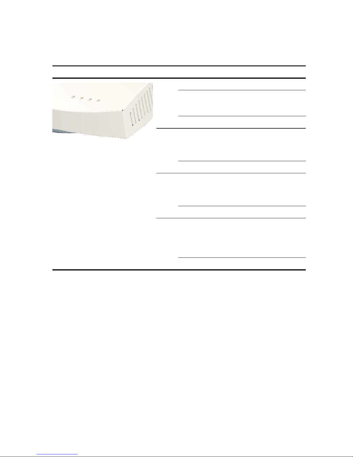
6. Controllo degli indicatori LED
Quando l'access point è collegato all'alimentazione elettrica, i LED indicano l'attività, come
descritto di seguito:
LED Colore Significato
Power Verde Unità accesa
Ambra Lampeggiante indica un guasto
hardware o che il sistema è in fase di
avvio.
Spento Unità spenta
11a Verde Indica che la rete 802.11a 5,0 GHz
wireless è attiva. Se il LED lampeggia,
il link wireless è presente ed è in corso
la trasmissione o la ricezione di dati.
Spento Il trasmettitore radio è disattivato
11b/g Verde Indica che la rete 802.11a 5,0 GHz
wireless è attiva. Se il LED lampeggia,
il link wireless è presente ed è in corso
la trasmissione o la ricezione di dati.
Spento Il trasmettitore radio è disattivato
LAN Verde Indica il rilevamento di una rete 10/
100Base-T sulla porta Ethernet. Se il
LED lampeggia, il link è presente ed è
in corso la trasmissione o la ricezione
di dati.
Spento Il trasmettitore radio è disattivato
7. Installazione del software
Il CD-ROM 3Com contiene le seguenti applicazioni e documentazione:
• Wireless Infrastructure Device Manager
• Manuale per l'utente
• Questa Guida introduttiva
Per rilevare e configurare l'access point, è necessario installare il software Wireless Infrastructure
Device Manager (WIDMan) sul computer.
1 Accendere il computer.
2 Inserire il CD di installazione 3Com nell'unità CD-ROM.
Verrà visualizzato il menu del CD. Se il menu non viene visualizzato, è possibile avviare il
menu Setup dal menu Start di Windows. Ad esempio: Start > Esegui > d:setup.exe.
3 Nel menu, fare clic su Utilities.
4 Nella schermata successiva, fare doppio clic su 3Com Wireless Infrastructure Device
Manager, quindi fare clic su Install per installare il software.
28
Page 31

5 Seguire le istruzioni visualizzate sullo schermo per completare l'installazione. Riavviare il
computer se viene richiesto.
6 Avviare lo strumento di utilità dal menu Start di Windows: selezionare Start > Programmi >
3Com Wireless > Wireless Infrastructure Device Manager.
8. Connessione all' access point
È possibile effettuare la connessione all'access point su reti con server DHCP e su reti prive di
server DHCP. Per effettuare la connessione è necessario individuare prima l'indirizzo IP
dell'access
Individuazione dell'indirizzo IP su reti con server DHCP
Se sulla rete è presente un server DHCP, all'access point viene assegnato automaticamente un
indirizzo IP. L'access
Utilizzare WIDMan per individuare l'access
la sezione
connesso alla stessa sottorete per visualizzare lo stato di sistema dell'access point o modificare la
sua configurazione.
Individuazione dell'indirizzo IP su reti senza server DHCP
point.
point richiede da uno a due minuti per rilevare un server DHCP sulla rete.
point sulla rete e visualizzare il suo indirizzo IP (vedere
“Uso di WIDMan”). Immettere quindi l'indirizzo IP in un browser Web su un computer
Se sulla rete non è presente un server DHCP, l'access point utilizza un indirizzo IP predefinito
assegnato dal produttore (169.254.2.2).
Uso di WIDMan
Il software WIDMan (Wireless Infrastructure Device Manager) 3Com consente di rilevare e
configurare l'access
l'indirizzo IP dell'access
1 Collegare il computer all'access point direttamente o tramite rete.
2 Avviare WIDMan dal menu Start di Windows: Start > Programmi > 3Com Wireless >
Wireless Infrastructure Device Manager.
Non appena l'access point viene rilevato, verrà visualizzato nella schermata Wireless Network
Tree.
3 Fare clic per selezionare l'access point, quindi fare clic sul pulsante Properties.
4 Annotare l'indirizzo IP dell'access point.
point. Eseguire le seguenti operazioni per utilizzare WIDMan per determinare
point.
29
Page 32

9. Configurazione dell' access point
Per configurare l'access point eseguire le seguenti operazioni:
1 Collegare l'access point e individuare il suo indirizzo IP come descritto nella sezione
“Connessione all' access point”.
2 Avviare il browser Web sul computer. Nella barra degli indirizzi, immettere l'indirizzo IP
dell'access
3 Nella schermata Access Point Login, digitare il nome utente e la password, quindi fare clic su
Log On.
Il nome utente e la password predefiniti distinguono tra maiuscole e minuscole:
• Nome utente: admin
• Password: password
4 Se è la prima volta che si effettua l'accesso all'access point, verrà richiesto di selezionare il
paese in cui si sta utilizzando il dispositivo. Scegliere il paese dal menu e fare clic su Apply.
5 Quindi, utilizzare Setup Wizard per configurare l'access point. Fare clic su Setup Wizard nel
menu nell'area sinistra dello schermo.
6 Seguire le istruzioni visualizzate sullo schermo. Utilizzare i pulsanti Next e Back per passare
da una schermata all'altra. Fare clic su Finish al termine dell'operazione.
point e premere Invio.
Per dettagli completi sull'uso di Wireless Infrastructure Device Manager e sulla configurazione
dell'access
nel CD del prodotto. Per eventuali aggiornamenti al manuale per l'utente, visitare il nostro sito
Web:
http://www.3Com.com.
point, consultare la 3Com Wireless 8760 11a/b/g PoE Access Point User Guide inclusa
10.Risoluzione dei problemi
Per informazioni sulla risoluzione dei problemi, consultare la Guida per l'utente o visitare il sito
Web di 3Com:
http://www.3Com.com.
30
Page 33

Kurzanleitung
3Com Drahtloser 8760
11a/b/g PoE Access Point
3CRWE876075 / WL-546
Der 3Com Drahtloser 8760 Access Point verbindet hohe Leistungsfähigkeit, die Fähigkeit zur
Zusammenarbeit und leichte Anwendbarkeit, um isolierte verdrahtete Netzwerke in ein
zusammenhängendes drahtloses Bereichs-Netzwerk (WLAN = wireless local area network)
einzubinden. Der Wireless
entsprechende Sicherheitsmerkmale und unterstützt Normen für drahtlose Netzwerke,
einschließlich 802.11a und 802.11g.
Diese Kurzanleitung beschreibt die grundlegenden Schritte zur Installation und Konfiguration Ihres
3Com Drahtloser
wird der Wireless
8760 11a/b/g PoE Access Point (3CRWE876075/WL-546). In diesem Handbuch
8760 Access Point kurz mit access point bezeichnet.
8760 Access Point beinhaltet außerdem stabile, den Normen
Über dieses Handbuch
Dieses Handbuch beschreibt die grundlegenden Schritte zur Installation des access point. Es
beinhaltet die folgenden Themen:
• Merkmale des 3Com Drahtlosen 8760 Access Point
• Sicherheitsinformationen
• Schritt 1: Auspacken des Access Point
• Schritt 2: Vorbereitung der Installation
• Schritt 3: Anbringen der Antennen
• Schritt 4: Montage des Access Point
• Schritt 5: Stromanschluss
• Schritt 6: Überprüfen der Leuchtdiodenanzeigen
• Schritt 7: Installation der Software
• Schritt 8: Verbindung aufnehmen mit dem access point
• Schritt 9: Konfigurierung des access point
• Fehlersuche
Page 34
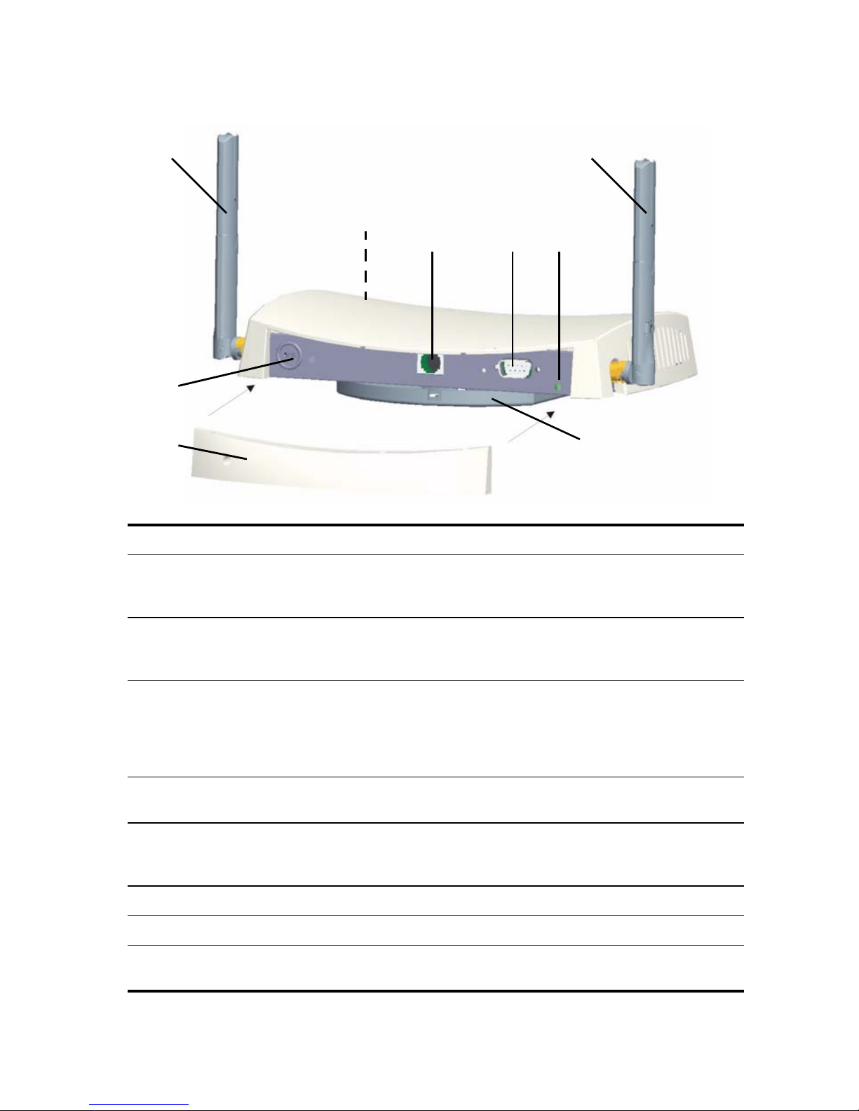
Merkmale des 3Com Drahtlosen 8760 Access
Point
1
1
2
43
5
6
78
Funktion Beschreibung
1 AntennenanschlüsseZwei RSMA-Antennenanschlüsse ermöglichen Ihnen den Anschluss
von Antennen, die im Funkbereich 2.4
werden.
2 Leuchtdioden Die Leuchtdioden zeigen die Stromversorgung und Aktivität an.
Einzelheiten finden Sie unter
Leuchtdiodenanzeigen” auf Seite 38.
3 Ethernet-
Schnittstelle
4 Serielle Schnittstelle Hierüber verfügt der access point über eine serielle Schnittstelle
5 Taste zum
Zurücksetzen
6 Buchse der Kensington-Diebstahlsicherung
7 Abnehmbare Rückwand-Abdeckung
Die Ethernet-Schnittstelle bietet eine 10/100BASE-TX EthernetVerbindung zu einem 3Com-Schalter. Verwenden Sie ein passendes
Kabel der Kategorie 5 (US) mit gerader Signalgebung und genormten
RJ-45-Anschlüssen (US), um Ihren access
Netzwerks anzuschließen.
zwecks Diagnose.
Um die Werkseinstellungen wieder herzustellen, führen Sie einen
spitzen Gegenstand in die Öffnung auf der Rückseite des access
ein und halten für zwei bis fünf Sekunden.
See “Überprüfen der
GHz und 5.3 GHz betrieben
point an dem Schalter des
point
8 Halterung Die Halterung ist mit dem access point verbunden und ermöglicht die
Wand- oder Deckenmontage des Geräts.
32
Page 35
Sicherheitsinformationen
Die Ausstattung muss gemäß den örtlichen und national geltenden Baunormen, behördlichen
Beschränkungen und den Bestimmungen der US-Behörde FCC (Federal Communications
Commission) installiert werden. Zur Sicherheit von Personen und der Ausrüstung darf der
access
point nur von Netwerkspezialisten installiert werden.
ACHTUNG: Dieser Abschnitt enthält Anweisungen, die Sie zugunsten der Sicherheit
Ihrer Mitarbeiter befolgen müssen. Befolgen Sie alle Anweisungen genau.
Vor Installation oder Entfernen des Geräts müssen Sie die folgenden Sicherheitsinformationen
genau lesen.
ACHTUNG: Bitte lassen Sie während der Installation und dem Entfernen des Geräts
ganz besondere Vorsicht walten.
ACHTUNG: Die Steckdose muss in der Nähe des Geräts und leicht zugänglich sein. Sie
können das Gerät nur durch Ziehen des Stromkabels aus der Steckdose vom
Stromkreislauf trennen.
ACHTUNG: Dieses Gerät wird unter SELV (Safety Extra Low Voltage=SicherheitsNiedrigspannung)-Bedingungen gemäß derIEC
Bedingungen können nur gewahrt bleiben, wenn die Ausrüstung, mit der das Gerät
verbunden ist, auch unter Niederspannungsbedingungen betrieben wird.
ACHTUNG: Es gibt keine elektischen Sicherungen, die vom Anwender ersetzt werden
können, oder für den Anwender zweckdienliche Teile im Inneren des Geräts. Wenn Sie
ein Problem mit dem Gerät haben, das nicht mit den in diesem Handbuch
beschriebenen Methoden der Problembehebung zu lösen ist, setzen Sie sich mit Ihrem
Lieferanten in Verbindung.
950 / IEC 60950-Norm betrieben. Diese
ACHTUNG: Ziehen Sie den Netzadapter heraus bevor Sie das Gerät bewegen.
ACHTUNG: RJ-45 Schnittstellen. Das sind geschützte RJ-45 Steckdosen. Sie können
nicht wie übliche Standard-Telefonsteckdosen genutzt bzw. das Gerät kann nicht mit
einem herkömmlichen PBX oder öffentlichen Telefonnetzwerk verbunden werden. Sie
können nur RJ-45 Datenanschlüsse, Telefoniesysteme für Netzwerke oder NetzwerkTelefone an diesen Steckdosen anschließen.
Sowohl geschützte als auch ungeschützte Datenkabel mit geschützten oder
ungeschützten Buchsen können an diese Steckdosen angeschlossen werden.
ACHTUNG: Gemäß den FCC-Beschränkungen bezüglich Strahlung durch Funk muss
bei Betrieb des access
betragen.
point die Mindestentfernung der Antenne zu einer Person 20 cm
Zulässige Kanäle
Das Produkt darf ausschließlich für in dem jeweiligen Land zugelassene Kanäle genutzt werden.
Wählen Sie Ihr Land aus der Länder-Auswahlliste, um die Installation korrekt auszuführen.
Gemäß den Gebrauchsbeschränkungen der US-Behörde FCC (Federal Communications
Commission) sind standardmäßig nur die Kanäle 1 – 11 verfügbar. Sofern die Nutzung der Kanäle
1 -13 in Ihrem Land zulässig ist, finden Sie die aktuellste Software-Version auf der 3Com-Website.
www.3Com.com
33
Page 36

1. Auspacken des Access Point
Stellen Sie sicher, dass Sie die folgenden Komponenten mit dem access point mitgeliefert wurden:
• Ein 3Com Wireless 8760 11a/b/g PoE access point
• Zwei externe Dual-Band Antennen (2.4 GHz und 5.3 GHz)
• Ein PoE-Injektor
• Ein Ethernet-Kabel
• Vorrichtung zur Wandmontage:
• Halterung (mit dem access point verbunden)
• Zwei Blechschrauben
• Zwei Schrauben
• Zwei Wandanker
• Vier haftende Gummifüße (für Montage auf ebener Oberfläche).
• Eine CD-ROM mit der Setup Wizard Software, das Benutzerhandbuch und ein Exemplar
dieser Kurzanleitung.
• Ein Garantieschein
2. Vorbereitung der Installation
Vor dem Einbau des access point an einem schlecht erreichbaren Ort ist es empfehlenswert die
Ethernet Kabel und die Leuchtdioden anzuschließen und zu überprüfen. Überprüfen Sie
außerdem vor Montage und Anschluss des access
point Folgendes:
Funktion Beschreibung
Schalter-Schnittstelle Um Ihr Funknetzwerk in Ihr verdrahtetes Netzwerk einzubinden,
benötigen Sie einen Hub oder einen Schalter, der an den access
angeschlossen ist.
Verkabelung Stellen Sie sicher, dass das standardmäßige Ethernet-Kabel mit gerader
Signalgebung vor Ort installiert ist, bevor Sie den access
installieren.
Stellen Sie sicher, dass das Kabel hochflexibel ist und dass der RJ-45Anschluss keine zusätzliche Abdeckung, die verhindern könnten, dass
das Kabel durch die Halterung geführt werden kann, hat
Anforderungen an die
Stromversorgung
MAC-Addresse Die MAC-Addresse an einem sicheren Ort notieren, bevor der
Die Stromversorgung ist durch ein 802.3af PoE-kompatibles Gerät
gewährleistet. Ein PoE-Injektor ist Teil des Lieferumfangs.
access
point an einem schwer erreichbaren Ort eingebaut wird.
Die MAC-Addresse befindet sich auf der Rückseite des access point.
Zusätzliche MAC-Adressen wurden mit dem access
point
point mitgeliefert.
point
34
Page 37

3. Anbringen der Antennen
Vorsichtig die mit dem access point mitgelieferte abschraubbare Standardantenne auspacken. Die
jeweilige Antenne am Antennenanschluss des access
Netzwerkinbetriebnahme kann es sein, dass die Antenne ausgerichtet werden muss, um ihre
gesamte Reichweite abzudecken.
Um die besten Ergebnisse zu erreichen, die Antenne senkrecht zum Boden und zur Decke
ausrichten.
WARNUNG: Die Antennenspitzen nicht berühren. Dies gilt insbesondere nach dem
Anschluss an den access
dadurch zur Beschädigung der Ausrüstung führen.
point. Dies kann zu elektrostrostatischer Entladung und
point von Hand festschrauben. Nach der
4. Montage des Access Point
Der Access Point kann auf folgenden Arten von Oberflächen montiert werden:
• Wand, Decke oder Schaltkasten (NEMA-Gehäuse); NEMA = National Electrical
Manufacturers Association (US)
• Tischplatte
Montage an Wand, Decke oder Schaltkasten
Benutzen Sie die mit Ihrem access point mitglelieferte Halterung zur Montage an Wand, Decke
oder im Schaltkasten. Verwenden Sie für zusätzliche Sicherheit die mitgelieferte Sperrleiste und
ein Schloss (nicht mitgeliefert), um den access
zu halten.
So bringen Sie den access point an einer Wand an:
1 Ethernet-Kabel durch die Öffnung in der Basisstation führen.
2 Die Halterung an der Wand, Decke oder im Schaltkasten (NEMA-Gehäuse) anschrauben:
• Bei Montage auf einer soliden Wand- oder Deckenoberfläche, die zwei Blechschrauben
verwenden.
• Bei Montage an einer Wand aus Trockenbauplatten, die zwei Blechschrauben und die
zwei Wandanker verwenden.
• Bei Montage im Schaltkasten (NEMA-Gehäuse), die zwei Schrauben verwenden:
point nach der Wandmontage in der Basisstation
35
Page 38
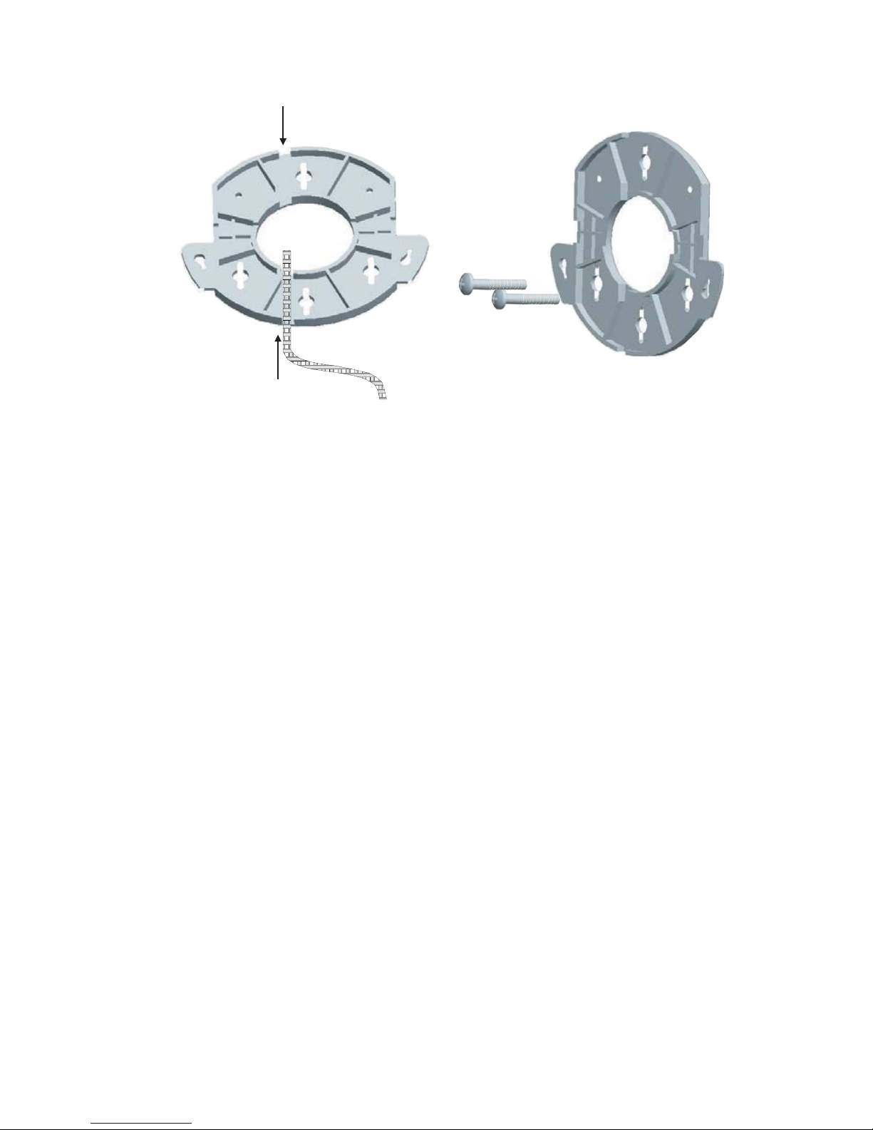
Die Abbildungen unten stellen den Verlauf eines Kabels durch die große Öffnung der
Basisstation und dann die Montage der Basisstation an der Wand dar.
3 Schließen Sie das Ethernet-Kabel (für Strom- und Netzwerkanschluss) an dem Anschluss an
der Vorderseite des access
point an.
4 Lassen Sie den access point in der Halterung einrasten.
Montage auf der Tischplatte:
So montieren Sie den access point an einer glatten Oberfläche wie z.B. einem Tisch:
1 Entfernen Sie die Rückseite von den vier Gummifüßen und bringe Sie sie an der Unterseite
der Halterung, die mit dem access
point verbunden ist, an.
2 Den access point auf dem Tisch platzieren.
3 Schließen Sie das Ethernet-Kabel (für Strom- und Netzwerkanschluss) an dem Anschluss an
der Vorderseite des access
point an.
5. Stromanschluss
Der access point kann auf folgende Art und Weise mit Strom versorgt werden:
• Durch die Stromversorgung über Ethernet (PoE); hier sorgt das LAN über ein 802.3af PoE-
kompatibles Gerät wie ein Schalter oder Hub für die Stromversorgung.
• Über PoE, wobei der mit dem access point mitgelieferte PoE-Injektor für die
Stromversorgung zuständig ist.
36
Page 39
Strom über Ethernet (PoE) vom LAN
3CRWX120695A
Wir
el
ess LAN Swit
ch WX1200
TO ACCESS POINT
TO HUB/SWITCH
Um den access point mit PoE über einen Schalter oder ein sonstiges 802.3af-kompatibles Bauteil
mit Strom zu versorgen, stecken Sie das Netzwerkkabel einfach vom Gerät in die EthernetSchnittstelle des access
point.
PoE-Schalter/-Hub
Access Point
Strom über Ethernet mit einem PoE-Injektor
Um den access point mit dem (mit dem Gerät mitglelieferten) 3Com-PoE-Injektor mit Strom zu
versorgen, führen Sie Folgendes aus:
1 Schließen Sie das LAN-Kabel vom Schalter oder Hub an die Hub/Schalter-Schnittstelle des
(mit dem access
point mitgelieferten) 3Com-PoE-Injektors an.
2 Danach verbinden Sie das LAN-Kabel der Ethernet-Schnittstelle des access point mit der
anderen Schnittstelle des PoE-Injektors.
3 Schließen Sie den PoE-Injektor an eine ordnungsgemäß geerdete Steckdose an.
Zum Access Point
Access Point
Zum Schalter/Hub
ch WX1200
LAN Swit
ess
Wirel
3CRWX120695A
Schalter/Hub
(nicht-PoE)
37
Page 40
6. Überprüfen der Leuchtdiodenanzeigen
Wenn der access point an den Strom angeschlossen ist, zeigen die Leuchtdioden die Aktivität wie
folgt an:
Leucht
diode
Betrieb Grün Ein
11a Grün Kennzeichnet, dass 802.11a 5.0 GHz
11b/g Grün Kennzeichnet, dass 802.11g2.4 GHz
Farbe Bedeutung
Orange Das Warnblinken weist auf einen
Gerätefehler oder auf das Booten des
Sytems hin.
Aus Aus
die drahtlose Netzwerkverbindung
besteht. Eine blinkende Leuchtdiode
bedeutet, dass die Verbindung
besteht und Daten übertragen
werden.
Aus Funk funktioniert nicht.
die drahtlose Netzwerkverbindung
besteht. Eine blinkende Leuchtdiode
bedeutet, dass die Verbindung
besteht und Daten übertragen
werden.
Aus Funk funktioniert nicht.
LAN Grün Kennzeichnet, dass ein 10/100Base-
T-Netzwerk an der EthernetSchnittstelle entdeckt wurde. Eine
blinkende Leuchtdiode bedeutet,
dass die Verbindung besteht und
Daten übertragen werden.
Aus Keine Verbindung
LAN Grün Kennzeichnet, dass ein a 10/100Base-
T Netzwerkan der EthernetSchnittstelle entdeckt wurde. Eine
blinkende Leuchtdiode bedeutet,
dass die Verbindung besteht und
Daten übertragen werden.
Aus Keine Verbindung
38
Page 41

7. Installation der Software
Die folgenden Anwendungen und Dokumente sind auf der 3Com CD-ROM enthalten:
• Gerätemanager der drahtlosen Infrastruktur
• Benutzerhandbuch
• Die Kurzanleitung
Sie müssen die Software "Gerätemanager der drahtlosen Infrastruktur" (WIDMan) auf Ihrem
Computer installieren, um mit dem access
installieren.
1 Schalten Sie Ihren Computer ein.
2 Legen Sie die die 3Com-Installations-CD in das CD-ROM-Laufwerk Ihres PCs ein.
Das CD-Menü wird angezeigt. Wenn es nicht angezeigt wird, können Sie das
Installationsprogramm vom Windows-Menü Start starten. Beispiel: Start > Ausführen >
d:setup.exe.
3 Im Menü Dienste anklicken.
4 Im nächsten Bildschirm 3Com Gerätemanager für drahtlose Infrastruktur doppelklicken
und dann Installieren klicken, um ihn zu installieren.
5 Folgen Sie den Bildschirmanweisungen, um die Installation fertigzustellen. Wenn Sie dazu
aufgefordert werden, starten Sie den Computer neu.
point kommunizieren zu können und ihn zu
6 Starten Sie die Zubehörfunktion vom Windows-Menü Start: Wählen Sie Start > Programme
> 3Com Wireless > Gerätemanager für drahtlose Infrastruktur.
8. Verbindung aufnehmen mit dem access point
Sie können mit dem access point in Netzwerken mit DHCP-Server und in Netzwerken ohne DHCPServer Verbindung aufnehmen (DHCP = dynamic host configuration protocol; Dynamisches
Konfigurationsprotokoll für Rechner) Für die Verbindung benötigen Sie die IP-Adresse des
access
point.
Suche der IP-Adresse in Netzwerken mit DHCPServer
Wenn Ihr Netzwerk einen DHCP-Server hat, ist dem access point automatisch eine IP-Adresse
zugeordnet. Der access
im Netzwerk zu finden. Lokalisieren Sie den access
Gerätemanager für drahtlose Infrastruktur, und lassen Sie sich seine IP-Adresse anzeigen (siehe
“Anhand von WIDMan”). Geben Sie danach die IP-Adresse in einen Web-Browser an einem
Computer im gleichen Unternetzwerk ein und lassen Sie sich den Systemstatus des access points
anzeigen oder ändern Sie seine Konfiguration.
point benötigt zwischen einer und zwei Minuten, um einen DHCP-Server
point im Netzwerk mit WIDMan, dem
Suche der IP-Adresse in Netzwerken ohne DHCPServer
Wenn Ihr Netzwerk keinen DHCP-Server hat, benutzt der access point eine vom Werk
zugewiesene IP-Adresse (169.254.2.2).
39
Page 42

Anhand von WIDMan
der Software 3 Com WIDMan (Gerätemanager für Drahtlose Infrastruktur) können Sie Ihren
access
point finden und konfigurieren. Befolgen Sie diese Schritte bei der Bestimmung der IP-
Adresse des access
point mit WIDMan.
1 Verbinden Sie Ihren Computer entweder direkt mit dem access point oder über das
Netzwerk.
2 Starten Sie WIDMan vom Windows-Menü Start: Start > Programme > 3Com Wireless >
Gerätemanager für drahtlose Infrastruktur.
Wenn Ihr access point gefunden wurde, wird er im Bildschirm "Baum des Drahtlosen
Netzwerks" angezeigt.
3 Klicken Sie auf access point, um diesen auszuwählen und klicken Sie anschließend auf die
Schaltfläche Eigenschaften.
4 Notieren Sie sich die IP-Adresse Ihres access points.
9. Konfigurierung des access point
Führen Sie folgende Schritte aus, um den access point zu konfigurieren:
1 Stellen Sie die Verbindung zum access point her und suchen Sie seine IP-Adresse wie unter
“Verbindung aufnehmen mit dem access point” beschrieben.
2 Starten Sie den Webbrowser Ihres Computers. Geben Sie die IP-Adresse Ihres access points in
der Adressleiste ein und drücken auf Eingabe.
3 Im Anmeldefenster des access points den Benutzernamen und das Kennwort eingeben und
Anmelden anklicken.
Beim Standard-Benutzernamen und dem Passwort ist auf Groß-/Kleinschreibung zu achten:
• Benutzername: admin
• Kennwort: Kennwort
4 Beim erstmaligen Anmelden beim access point werden Sie aufgefordert, das Land
auszuwählen, in dem Sie das Gerät nutzen. Wählen Sie Ihr Land und drücken dann auf
Anwenden.
5 Gehen Sie dann zum Installations-Wizard, um Ihren access point zu konfigurieren. Klicken
Sie Installations-Wizard im Menü auf der linken Seite des Bildschirms.
6 Folgen Sie den Bildschirmanweisungen. Bewegen Sie sich mit den Schaltflächen Nächster
und Zurück durch die Bildschirme. Klicken Sie Beenden wenn Sie fertig sind.
Alle Einzelheiten über den Gebrauch des Gerätemanagers für drahtlose Infrastruktur und die
Konfiguration Ihres access
PoE Access Point-Benutzerhandbuch. Aktualisierungen des Benutzerhandbuchs finden Sie ggf. auf
unserer Internetseite:
http://www.3com.com.
point, finden Sie auf der Produkt-CD im 3Com Wireless 8760 11a/b/g
10.Fehlersuche
Informationen zur Fehlersuche finden Sie im Benutzerhandbuch oder auf der 3Com-Webseite:
http://www.3com.com.
40
Page 43

Guía de inicio rápido
Punto de acceso inalámbrico PoE
11a/b/g 3Com 8760
3CRWE876075 / WL-546
El Punto de acceso inalámbrico PoE 11a/b/g 3Com 8760 combina alto rendimiento,
interoperabilidad y facilidad de uso para unir redes alámbricas aisladas en una cohesiva red de
área local inalámbrica (WLAN, Wireless Local Area Network). El Punto de acceso inalámbrico
también incluye sólidas funciones de seguridad basadas en estándares y soporta estándares de
redes inalámbricas como 802.11a y 802.11g.
Esta Guía de inicio rápido describe los pasos básicos necesarios para instalar y configurar su Punto
de acceso inalámbrico PoE 11a/b/g 3Com
guía el Punto de acceso inalámbrico
8760 (3CRWE876075 / WL-546). A lo largo de esta
8760 se denomina simplemente Punto de acceso.
8760
Acerca de esta Guía
Esta guía describe la instalación básica del Punto de acceso. Se tratan los siguientes temas:
• Características del Punto de acceso inalámbrico 3Com 8760
• Información de seguridad
• Paso 1: Desempaque del Punto de acceso
• Paso 2: Preparación para la instalación
• Paso 3: Conexión de las antenas
• Paso 4: Montaje del Punto de acceso
• Paso 5: Conexión de la alimentación
• Paso 6: Revisión de los indicadores LED
• Paso 7: Instalación del software
• Paso 8: Conexión al Punto de acceso
• Paso 9: Configuración del Punto de acceso
• Solución de problemas
Page 44
Características del Punto de acceso inalámbrico
3Com
8760
1
1
2
43
5
6
78
Característica Descripción
1 Conectores de
antena
2 LED Los LED indican la alimentación y la actividad. Consulte “Revisión de
3 Puerto Ethernet El puerto Ethernet proporciona una conexión de 10/100BASE-TX
4 Puerto serial Proporciona al Punto de acceso una interfaz serial para su uso en
5 Botón de reinicio Para restaurar los ajustes de fábrica, inserte un objeto puntiagudo en
6 Conector para cerradura Kensington
7 Cubierta extraíble del panel posterior
8 Montante de
soporte
Dos conectores de antena tipo RSMA permiten conectar antenas que
operan en las bandas de 2,4
los indicadores LED” en la página 48 para conocer detalles.
Ethernet a un conmutador 3Com. Para hacer la conexión del Punto
de
acceso al conmutador en la red, utilice un cable Categoría 5
adecuado con señalización directa y conectores RJ-45 estándar.
diagnósticos.
el orificio de reinicio en la parte de atrás del Punto de
manténgalo presionado durante dos a cinco segundos.
El montante de soporte viene unido al Punto de acceso y permite
montar la unidad en la pared o el techo.
GHz y 5,0 GHz.
acceso y
42
Page 45

Información de seguridad
Este equipos se debe instalar conforme a los códigos de edificación locales y nacionales, las
restricciones reglamentarias y las reglas de la FCC. Para la seguridad de personas y equipos, el
Punto de
Antes de instalar o quitar la unidad, debe leer atentamente la siguiente información de
seguridad.
acceso debe ser instalado sólo por personal profesional de redes.
ADVERTENCIA: las advertencias contienen instrucciones que usted debe seguir para
su seguridad personal. Siga atentamente todas las instrucciones.
ADVERTENCIA: se debe tener excepcional cuidado durante la instalación y retirada de
la unidad.
ADVERTENCIA: la toma de corriente del enchufe debe estar cerca de la unidad y ser
fácilmente accesible. Usted sólo puede retirar la alimentación de la unidad
desconectando el cable de alimentación de la toma de corriente.
ADVERTENCIA: esta unidad opera bajo condiciones de SELV (Safety Extra Low Voltage
o Voltaje extra-bajo de seguridad) según IEC
mantienen si el equipo al que está conectado también opera bajo condiciones de SELV.
ADVERTENCIA: dentro de la unidad no hay piezas que el usuario pueda reemplazar o
a las que pueda dar servicio. Si tiene un problema físico con la unidad que no pueda
resolverse con las medidas de resolución de problemas que aparecen en esta guía,
póngase en contacto con su proveedor.
950 / IEC 60950. Las condiciones sólo se
ADVERTENCIA: desconecte el adaptador de alimentación antes de mover la unidad.
ADVERTENCIA: puertos RJ-45. Estos son enchufes de datos RJ-45 blindados. No se
pueden utilizar como enchufes para teléfonos tradicionales estándar ni para conectar la
unidad a una PBX tradicional o a una red telefónica pública. Conecte a estos enchufes
sólo conectores de datos RJ-45, sistemas de telefonía de red o teléfonos de red.
Se pueden conectar a estos enchufes de datos cables de datos blindados o sin blindar
con clavijas blindadas o sin blindar.
ADVERTENCIA: para cumplir con los límites de exposición a la radiofrecuencia (RF) de
la FCC, se debe mantener una distancia mínima de 20 centímetros (8 pulg.) entre el
cuerpo y la antena cuando el Punto de
acceso está en funcionamiento.
Canales aprobados
El uso de este producto sólo está autorizado para los canales aprobados por cada país. Para lograr
una instalación adecuada, seleccione su país en la lista de selección de países.
Para acatar las restricciones de uso de canales de la FCC, en forma predeterminada sólo están
disponibles los canales 1 al 11. Si en su país se permite el uso de los canales 1 al 13, visite el sitio
Web de 3Com para obtener la última versión del software.
www.3Com.com
43
Page 46

1. Desempaque del Punto de acceso
Asegúrese de tener los siguientes elementos, que vienen con el Punto de acceso:
• Un Punto de acceso inalámbrico PoE 11a/b/g 3Com 8760
• Dos antenas externas de doble banda (2,4 GHz y 5,0 GHz)
• Un inyector PoE (Power over Ethernet)
• Un cable Ethernet
• Herrajes para montaje en pared:
• Soporte de montaje (conectado al Punto de acceso)
• Dos tornillos para planchas metálicas
• Dos tornillos roscados
• Dos anclajes para pared
• Cuatro patas de goma adhesivas (que se utilizan para la instalación en superficie plana).
• Un CD-ROM que contiene el software Setup Wizard (Asistente de configuración), el Manual
del usuario y una copia de esta Guía de inicio rápido.
• Un volante de garantía
2. Preparación para la instalación
Antes de instalar el Punto de acceso en un lugar de difícil acceso, es aconsejable conectar y revisar
el cable Ethernet y los LED. Además, observe los siguientes elementos antes de montar o conectar
el Punto de
Característica Descripción
Puerto para el
conmutador
Cableado Antes de instalar el Punto de acceso, asegúrese de que se encuentre
Requisitos de
alimentación
Dirección MAC Registre la dirección MAC en un lugar seguro antes de instalar el Punto
acceso:
Para conectar su red inalámbrica a su red alámbrica, necesita un
concentrador o conmutador conectado al Punto de
instalado en el sitio un cable Ethernet estándar con señalización
directa.
Asegúrese de que el cable sea altamente flexible y de que no haya
cobertura adicional en el conector RJ-45 que pueda impedir el
enrutamiento del cable de a través del montante de soporte.
La alimentación se suministra mediante un dispositivo compatible con
802.3af Power Over Ethernet (PoE). Se incluye un inyector PoE.
de
acceso en una ubicación de difícil acceso.
La dirección MAC está impresa en la parte de atrás del Punto
de
acceso. Con el Punto de acceso vienen otras etiquetas de dirección
MAC.
acceso.
44
Page 47

3. Conexión de las antenas
Desempaque cuidadosamente las antenas desmontables estándar que vienen con el Punto
de
acceso. Atornille cada antena en un conector de antena del Punto de acceso y apriétela a
mano. Después de iniciar la red, puede que deba ajustar las antenas para mejorar la cobertura en
su área.
Para obtener los mejores resultados, ajuste las antenas para que queden perpendiculares al piso y
al techo.
PRECAUCIÓN: no toque las puntas de las antenas, especialmente después de
conectarlas al Punto de
lo que puede dañar el equipo.
acceso. Esto podría producir una descarga electrostática (ESD),
4. Montaje del Punto de acceso
El Punto de acceso se puede montar en los siguientes tipos de superficies:
• Pared, techo o caja eléctrica (gabinete NEMA)
• Sobremesa
Montaje en pared, techo o caja eléctrica
Utilice el montante de soporte que viene con el Punto de acceso para instalarlo en una pared,
techo o caja eléctrica. Para mayor seguridad, utilice la barra de bloqueo incluida y un cerrojo (no
incluido) para bloquear el Punto de
acceso en el soporte después de montarlo en una pared.
Para montar el Punto de acceso en la pared:
1 Enrute el cable Ethernet a través de la abertura en el soporte.
2 Atornille el montante de soporte a una pared, techo o caja eléctrica (gabinete NEMA):
• Si lo monta en una pared o techo de superficie sólida, utilice los dos tornillos para
planchas metálicas.
• Si lo monta en tablarroca, utilice los dos tornillos para planchas metálicas y dos anclajes
para pared.
• Si lo monta en una caja eléctrica (gabinete NEMA), utilice los dos tornillos roscados.
45
Page 48
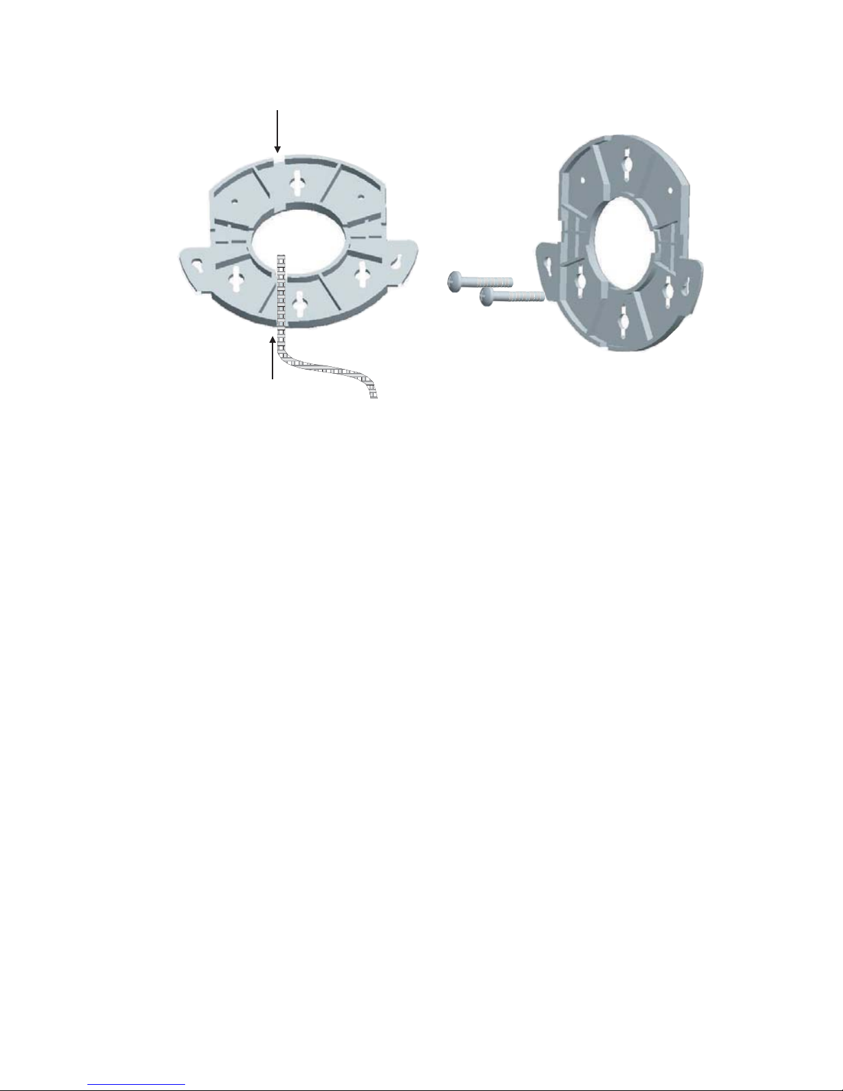
Las siguientes figuras ilustran el enrutamiento de un cable a través de la abertura grande en
el soporte y luego el montaje del soporte en una pared.
3 Conecte el cable Ethernet (para la alimentación y la conexión a la red) al puerto en la parte
delantera del Punto de
acceso.
4 Encaje el Punto de acceso en el montante de soporte.
Montaje de sobremesa
Para instalar el Punto de acceso sobre una superficie plana como una mesa o escritorio:
1 Retire el respaldo de las cuatro patas de goma e instálelas en la parte inferior del montante
de soporte en que está instalado el Punto de
acceso.
2 Coloque el Punto de acceso sobre la mesa.
3 Conecte el cable Ethernet (para la alimentación y la conexión a la red) al puerto en la parte
delantera del Punto de
acceso.
5. Conexión de la alimentación
El Punto de acceso se puede alimentar con los siguientes métodos:
• Con Power Over Ethernet (PoE) suministrado a través de la LAN por un dispositivo compatible
con 802.3af PoE como un conmutador o concentrador.
• Con PoE suministrado por el inyector PoE incluido con el Punto de acceso.
46
Page 49
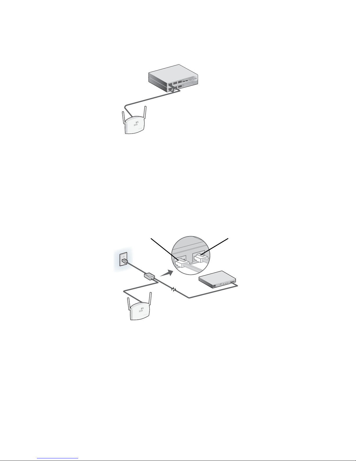
Power Over Ethernet (PoE) de la LAN
3CRWX1206
9
5A
Wir
el
ess LAN
Swit
ch WX1200
TO ACCESS POINT
TO HUB/SWITCH
Para alimentar el Punto de acceso utilizando PoE proporcionado por un conmutador u otro
dispositivo compatible con 802.3af, simplemente enchufe el cable de red del dispositivo en el
puerto Ethernet del Punto de
acceso.
Conmutador/concentrador PoE
Punto de acceso
Power Over Ethernet de un inyector PoE
Para alimentar el Punto de acceso utilizando el inyector PoE 3Com (incluido con la unidad), haga
lo siguiente:
1 Conecte el cable LAN del conmutador o concentrador al puerto para conmutador/
concentrador en el inyector PoE 3Com (incluido con el Punto de
2 Luego, conecte un cable LAN del puerto Ethernet en el Punto de acceso al otro puerto en el
inyector PoE.
acceso).
3 Enchufe el inyector PoE en una toma de corriente eléctrica correctamente conectada a tierra.
Al Punto de acceso Al conmutador/concentrador
ch WX1200
LAN Swit
ess
el
Wir
5A
9
3CRWX1206
Conmutador/concentrador
(no PoE)
Punto de acceso
47
Page 50
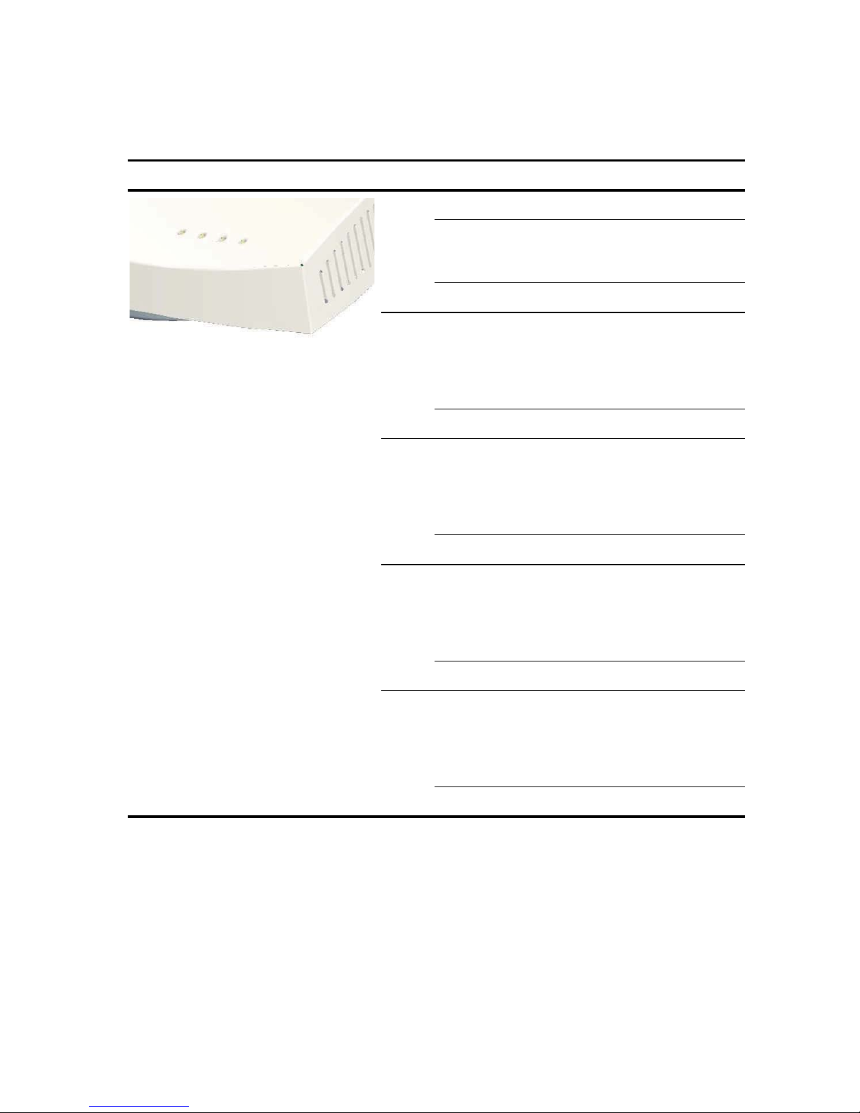
6. Revisión de los indicadores LED
Cuando el Punto de acceso está conectado a la alimentación, los LED indican actividad de la
siguiente manera:
LED Color Indica
Alimen
tación
11a Verde Indica que 802.11a 5.0 GHz está
11b/g Verde Indica que 802.11g2.4 GHz está
LAN Verde Indica que se detecta una red 10/
Verde Alimentación activada
Ámbar parpadeante indica una falla de
hardware o el sistema se está
iniciando.
Apagado Alimentación desactivada
habilitada. Si el LED está destellando,
el enlace inalámbrico es correcto y se
están transmitiendo o recibiendo
datos.
Apagado La radio está apagada
habilitada. Si el LED está destellando,
el enlace inalámbrico es correcto y se
están transmitiendo o recibiendo
datos.
Apagado La radio está apagada
100Base-T en el puerto Ethernet. Si el
LED está destellando, el enlace es
correcto y se están transmitiendo o
recibiendo datos.
Apagado No hay enlace
10 Verde Indica que se detecta una red
10Base-T en el puerto Ethernet. Si el
LED está destellando, el enlace es
correcto y se están transmitiendo o
recibiendo datos.
Apagado No hay enlace
7. Instalación del software
En el CD-ROM 3Com se incluyen las siguientes aplicaciones y documentos:
• Wireless Infrastructure Device Manager
• Manual de usuario
• Esta Guía de inicio rápido
48
Page 51

Usted debe instalar el software Wireless Infrastructure Device Manager (WIDMan) en su
computadora para descubrir y configurar el Punto de
acceso.
1 Encienda su computadora.
2 Inserte el CD de instalación 3Com en la unidad de CD-ROM.
Aparece el menú del CD. Si no aparece, usted puede iniciar el menú Setup (Configuración)
desde el menú Inicio de Windows. Por ejemplo: Inicio > Ejecutar > d:setup.exe.
3 En el menú, haga clic en Utilities (Utilidades).
4 En la siguiente pantalla, haga doble clic en 3Com Wireless Infrastructure Device
Manager y luego haga clic en Install (Instalar) para instalarlo.
5 Siga las instrucciones en las pantallas para completar la instalación. Reinicie la computadora
si se le pide hacerlo.
6 Lance la herramienta desde el menú Inicio de Windows: seleccione Inicio > Programas >
3Com Wireless > Wireless Infrastructure Device Manager.
8. Conexión al Punto de acceso
Puede conectarse al Punto de acceso en redes que tengan un servidor DHCP y en redes que no
tengan un servidor DHCP. Para conectarse debe encontrar la dirección IP del Punto de
acceso.
Búsqueda de la dirección IP en redes con un servidor DHCP
Si su red tiene un servidor DHCP, se asigna automáticamente una dirección IP al Punto de acceso.
El Punto de
WIDMan para ubicar el Punto de
WIDMan”). Luego, ingrese esa dirección IP en un explorador Web en una computadora que esté
en la misma subred para ver el estado del sistema del Punto de acceso o cambiar su configuración.
acceso tarda entre uno y dos minutos en detectar un servidor DHCP en la red. Use
acceso en la red y ver su dirección IP (consulte “Uso de
Búsqueda de la dirección IP en redes sin un servidor DHCP
Si su red no tiene un servidor DHCP, el Punto de acceso usa una dirección IP predeterminada
asignada en fábrica (169.254.2.2).
Uso de WIDMan
El software 3Com WIDMan (Wireless Infrastructure Device Manager) le permite descubrir y
configurar el Punto de
IP del Punto de
acceso.
1 Conecte su computadora al Punto de acceso ya sea directamente o a través de la red.
2 Lance WIDMan desde el menú Inicio de Windows: Inicio > Programas > 3Com Wireless >
Wireless Infrastructure Device Manager.
Cuando se detecte su Punto de acceso, aparecerá en la pantalla Wireless Network Tree
(Árbol de la red inalámbrica).
acceso. Siga estos pasos para utilizar WIDMan para determinar la dirección
3 Haga clic para seleccionar su Punto de acceso y luego haga clic en el botón Properties
(Propiedades).
4 Tome nota de la dirección IP de su Punto de acceso.
49
Page 52

9. Configuración del Punto de acceso
Para configurar el Punto de acceso siga estos pasos:
1 Conéctese al Punto de acceso y encuentre su dirección IP como se describe en “Conexión al
Punto de acceso”.
2 Lance el explorador Web de su computadora. En la barra de dirección, ingrese la dirección IP
de su Punto de
3 En la pantalla de conexión del Punto de acceso, ingrese el nombre de usuario y la contraseña
y haga clic en Log On (Conectar).
El nombre de usuario y la contraseña predeterminados distinguen entre mayúsculas y
minúsculas:
• Nombre de usuario: admin
• Contraseña: password
4 Si esta es la primera vez que se conecta al Punto de acceso, se le pedirá que seleccione el país
en que utilizará el dispositivo. Elija su país del menú y luego haga clic en Apply (Aplicar).
5 Luego, use Setup Wizard para configurar su Punto de acceso. Haga clic en Setup Wizard en
el menú en el lado izquierdo de la pantalla.
6 Siga las indicaciones en pantalla. Utilice los botones Next (Siguiente) y Back (Atrás) para
moverse a través de las pantallas. Haga clic en Finish (Finalizar) cuando haya terminado.
acceso y presione Enter.
Para obtener detalles completos acerca de la utilización de Wireless Infrastructure Device Manager
y la configuración de su Punto de
inalámbrico PoE 11a/b/g 3Com
manual del usuario pueden encontrarse en nuestro sitio Web:
http://www.3Com.com.
acceso, consulte la Guía del usuario del Punto de acceso
8760 que viene en el CD del producto. Las actualizaciones al
10.Solución de problemas
Para obtener información de solución de problemas, consulte la Guía del usuario o visite el sitio en
el World Wide Web de 3Com:
http://www.3Com.com.
50
Page 53

Guia de Início Rápido
3Com Wireless 8760
11a/b/g PoE Access Point
3CRWE876075 / WL-546
O Wireless 8760 11a/b/g PoE Access Point combina alto desempenho, interoperabilidade e fácil
utilização para integrar redes com fio isoladas com uma rede local sem fio (WLAN) coesa. O
Wireless
suporta padrões de rede sem fio, inclusive 802.11a e 802.11g.
Este Guia de Início Rápido descreve as etapas básicas necessárias para instalar e configurar o
3Com Wireless
PoE Access Point (3CRWE876075/WL-546). Neste Guia, o Wireless
chamado de Access
8760 Access Point inclui também recursos de segurança robustos com base em padrões e
8760 11a/b/g PoE Access Point (3CRWE876075/WL-546).Wireless 8760 11a/b/g
8760 Access Point será
Point.
Sobre este Guia
Este guia descreve a instalação básica do Access Point. Os seguintes tópicos são apresentados:
• Recursos do 3Com Wireless 8760 Access Point
• Informações de Segurança
• Etapa 1: Componentes do Pacote do Access Point
• Etapa 2: Preparação da Instalação
• Etapa 3: Conexão das Antenas
• Etapa 4: Montagem do Access Point
• Etapa 5: Conexão da Alimentação
• Etapa 6: Verificação dos Indicadores LED
• Etapa 7: Instalação do Software
• Etapa 8: Conexão com o Access Point
• Etapa 9: Configuração do Access Point
• Diagnóstico de Problemas
Page 54
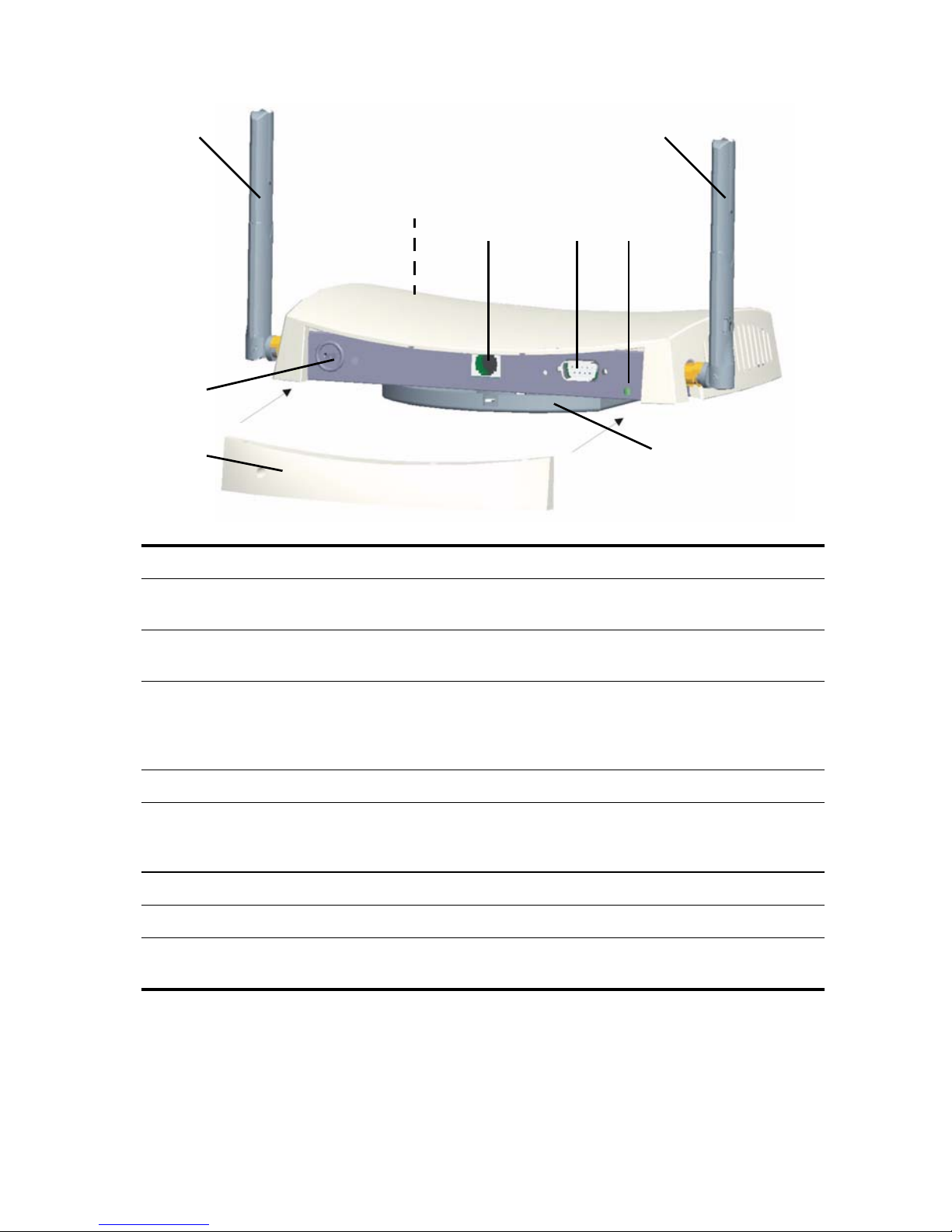
Recursos do 3Com Wireless 8760 Access Point
1
1
2
43
5
6
78
Recurso Descrição
1 Conectores da
Antena
2 LEDs Os LEDs indicam atividade e alimentação. Consulte “Verificação dos
3 Porta Ethernet A porta Ethernet oferece uma conexão 10/100BASE-TX Ethernet para
4 Porta Serial Fornece uma interface serial ao Access Point para uso do diagnóstico.
5 Botão de
Reinicialização
6 Conector de fechamento Kensington
7 Tampa destacável do painel traseiro
8 Suporte de
Montagem
Dois conectores de antena RSMA permitem a conexão de antenas que
operam nas bandas de 2,4
Indicadores LED” na página 58 para obter detalhes.
um switch 3Com. Use um cabo Categoria 5 adequado com sinalização
direta e conectores RJ-45 padrão para conectar o Access
switch na rede.
Para restaurar as configurações de fábrica, insira um objeto pontudo
no orifício de reinicialização na parte traseira do Access
mantenha por dois a cinco segundos.
suporte de montagem vem conectado ao Access Point e permite que
a unidade seja montada na parede ou no teto.
GHz e 5,3 GHz.
Point ao
Point e
52
Page 55

Informações de Segurança
Este equipamento deve ser instalado em conformidade com códigos, restrições regulamentares e
regras de FCC específicas ao local e ao país. Para garantir a segurança das pessoas e dos
equipamentos, o Access
rede.
ADVERTÊNCIA: As advertências contêm instruções que devem ser seguidas para sua
segurança pessoal. Siga todas as instruções cuidadosamente.
Leia cuidadosamente as informações de segurança a seguir antes de instalar ou remover a
unidade.
ADVERTÊNCIA: Deve-se tomar muito cuidado durante a instalação e remoção da
unidade.
ADVERTÊNCIA: A tomada deve estar próxima à unidade e ter fácil acesso. Só é
possível remover a alimentação da unidade desconectando o cabo de alimentação da
tomada.
ADVERTÊNCIA: Esta unidade funciona em condições SELV (Safety Extra Low Voltage)
de acordo com o IEC
equipamento ao qual ela estiver conectada também funcionar nas mesmas condições.
ADVERTÊNCIA: Não há fusíveis substituíveis pelo usuário nem partes utilizáveis no
interior da unidade. Se ocorrer um problema físico com a unidade que não possa ser
resolvido com as ações para solução de problemas neste guia, contate o fornecedor.
Point só deve ser instalado por técnicos profissionais especializados em
950 / IEC 60950. As condições só serão mantidas se o
ADVERTÊNCIA: Desconecte o adaptador de alimentação antes de mover a unidade.
ADVERTÊNCIA: Portas RJ-45 . Estes são soquetes de dados RJ-45 blindados. Eles não
podem ser usados como soquetes de telefone tradicional padrão ou para conectar a
unidade a uma rede telefônica pública ou de PBX tradicional. Conecte apenas
conectores de dados RJ-45, sistemas de telefonia de rede ou telefones de rede a esses
soquetes.
Cabos de dados blindados, ou não, com jaques blindados, ou não, podem ser
conectados aos soquetes de dados.
ADVERTÊNCIA: Para atender aos limites de exposição a freqüência de rádio (RF) do
FCC, deve-se observar uma distância mínima de 20 cm (8 pol) entre a antena e as
pessoas quando o Access
Point estiver em operação.
Canais Aprovados
O uso deste produto é autorizado apenas para os canais aprovados pelo país. Para a instalação
correta, selecione seu país na lista de seleção de país.
Para estar em conformidade com as restrições de uso de canal do FCC, apenas os canais 1–11
estão disponíveis, por padrão. Se os canais 1–13 puderem ser usados no seu país, visite o site da
3Com para obter a última versão do software.
www.3Com.com
53
Page 56

1. Componentes do Pacote do Access Point
Ao desembalar o Access Point, verifique se os seguintes componentes estão presentes:
• Um 3Com Wireless 8760 11a/b/g PoE Access Point
• Duas antenas externas com banda dupla (2,4 GHz e 5,3 GHz)
• Um injetor PoE (Power over Ethernet)
• Um cabo Ethernet
• Ferragens para montagem em parede:
• Suporte de montagem (conectado ao Access Point)
• Dois parafusos de chapa metálica
• Dois parafusos com rosca
• Duas buchas
• Quatro pés de borracha adesivos (usados para instalação em superfícies planas).
• Um CD-ROM contendo do software de Assistente de Configuração, o Manual do Usuário e
uma cópia deste Guia de Início Rápido.
• Um Folheto de Garantia
2. Preparação da Instalação
Convém conectar e verificar o funcionamento do cabo de Ethernet e dos LEDs antes de instalar o
Access
Point em um local de difícil acesso. Além disso, os seguintes itens devem ser observados
antes de montar ou conectar o Access
Recurso Descrição
Porta de Switch Para conectar a rede sem fio à rede com fio, é necessário conectar um
hub ou switch ao Access
Cabeamento Garanta que um cabo Ethernet padrão com sinalização direta já esteja
instalado no local antes de instalar o Access
Garanta que o cabo seja bastante flexível e que não haja revestimento
adicional no conector RJ-45 que impeça seu encaminhamento através
do suporte de montagem.
Requisito de Alimentação A alimentação é fornecida por um dispositivo compatível com 802.3af
Power Over Ethernet (PoE). Um injetor PoE é incluído.
Endereço MAC Registre o endereço MAC do ponto de acesso do Access Point em um
local seguro antes de instalá-lo em um local de difícil acesso.
O endereço MAC está impresso na parte traseira do Access Point.
Etiquetas adicionais com o endereço MAC são fornecidas com o
Access
Point:
Point.
Point.
Point.
54
Page 57

3. Conexão das Antenas
Desembale cuidadosamente as antenas destacáveis padrão fornecidas com o Access Point.
Parafuse cada antena em um conector da antena do Access
Após a rede ser inicializada, pode ser necessário fazer o ajuste fino das antenas para a cobertura
da área.
Para obter os melhores resultados, ajuste as antenas numa posição perpendicular ao piso e ao
teto.
CUIDADO: Não manuseie a antena pelas extremidades, especialmente após ser
conectada ao Access
danificar o equipamento.
Point. Isto pode resultar em descarga eletrostática (ESD) e
Point até que elas fiquem firmes.
4. Montagem do Access Point
O ponto de acesso pode ser montado nos seguintes tipos de superfícies:
• Parede, teto ou caixa elétrica (invólucro NEMA)
• Mesa
Montagem em parede, teto ou caixa elétrica
Use o suporte de montagem, fornecido com o Access Point para fazer a instalação na parede, no
teto ou na caixa elétrica. Para segurança adicional, use a barra de travamento incluída e uma trava
(não fornecida) para fixar o Access
Point à base após sua montagem na parede.
Para montar o Access Point na parede:
1 Passe o cabo Ethernet pela abertura na base.
2 Parafuse o suporte de montagem na parede, no teto ou na caixa elétrica (invólucro NEMA):
• Se estiver montando em uma superfície sólida como parede ou teto, use os dois parafusos
de chapa metálica.
• Se estiver montando em uma drywall, use os dois parafusos e as duas buchas.
• Se estiver montando em uma caixa elétrica (invólucro NEMA), use os dois parafusos com
rosca
55
Page 58
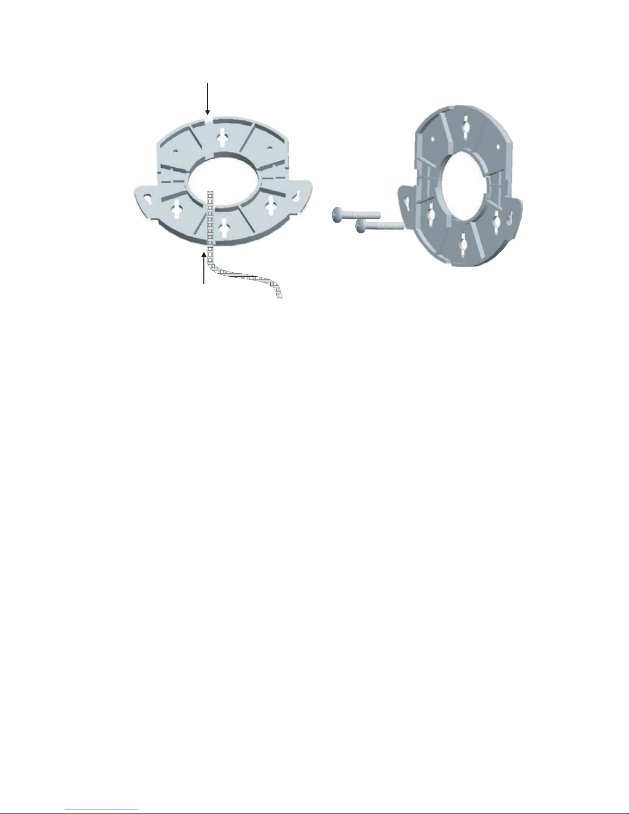
As figuras abaixo mostram um cabo passando pela abertura grande na base e, em seguida, a
base sendo montada em uma parede.
3 Conecte o cabo Ethernet (para conexão de alimentação e rede) à porta na frente do
Access
Point.
4 Encaixe o Access Point no suporte de montagem.
Montagem em Mesa
Para instalar o Access Point em uma superfície plana:
1 Remova o revestimento dos quatro pés de borracha e coloque-os na parte inferior do
suporte de montagem, fixado ao Access
Point.
2 Coloque o Access Point na mesa.
3 Conecte o cabo Ethernet (para conexão de alimentação e rede) à porta na frente do
Access
Point.
5. Conexão da Alimentação
O Access Point pode ser alimentado das seguintes maneiras:
• Por Power Over Ethernet (PoE) fornecida pela LAN por um dispositivo compatível com
802.3af PoE como um switch ou hub.
• Por PoE fornecida pelo injetor PoE fornecido com o Access Point.
56
Page 59
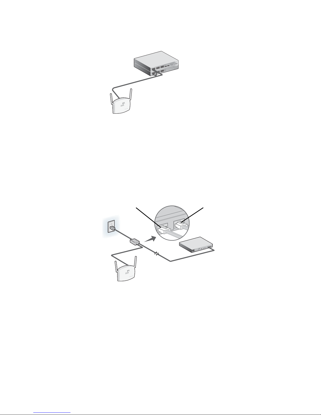
Power Over Ethernet (PoE) da LAN
3CRWX120695A
Wir
el
ess LAN Swit
ch WX1200
TO ACCESS POINT
TO HUB/SWITCH
Para alimentar o Access Point usando PoE fornecida por um switch ou outro dispositivo compatível
com 802.3af, basta conectar o cabo de rede do dispositivo à porta Ethernet do Access
Point.
PoE Switch/Hub
Access Point
Power Over Ethernet de um Injetor PoE
Para alimentar o Access Point usando o Injetor PoE da 3Com (fornecido com a unidade), faça o
seguinte:
1 Conecte o cabo da LAN do switch ou hub à porta Hub/Switch no Injetor PoE da 3Com
(fornecido com o Access
2 A seguir, conecte um cabo de LAN da porta Ethernet no Access Point à outra porta no injetor
PoE.
Point).
3 Conecte o Injetor PoE a uma tomada elétrica aterrada adequadamente.
Para o Access Point Para o Switch/Hub
0
ch WX120
LAN Swit
s
es
Wirel
3CRWX120695A
Access Point
Switch/Hub
(não-PoE)
57
Page 60
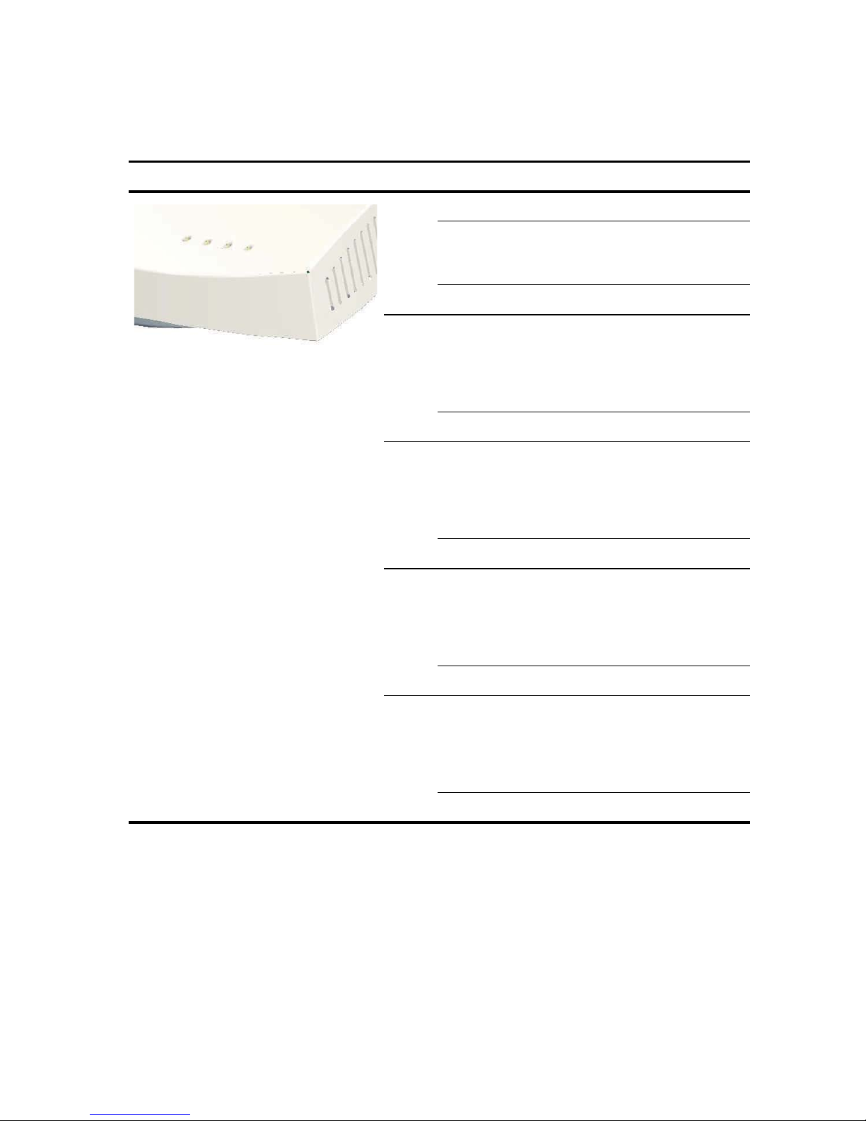
6. Verificação dos Indicadores LED
Quando o Access Point for conectado à eletricidade, os LEDs indicarão a atividade como a
seguir:
LED Cor Indica
Alimen
tação
11a Verde Indica que 802.11a 5.0 GHz a rede
11b/g Verde Indica que 802.11a 5.0 GHz a rede
LAN Verde Indica que uma rede 10/100Base-T
Verde Alimentação Ligada
Âmbar Piscando indica uma falha de
hardware ou que o sistema esta
reinicializando.
Apagado Alimentação Desligada
sem fio está ativada. Se o LED estiver
piscando, a conexão sem fio está
funcionando e dados estão sendo
transmitidos ou recebidos.
Apagado O rádio está desligado
sem fio está ativada. Se o LED estiver
piscando, a conexão sem fio está
funcionando e dados estão sendo
transmitidos ou recebidos.
Apagado O rádio está desligado
foi detectada na porta Ethernet. Se o
LED estiver piscando, a conexão está
funcionando e dados estão sendo
transmitidos ou recebidos.
Apagado Sem conexão
10 Verde Indica que uma rede 10Base-T foi
detectada na porta Ethernet. Se o
LED estiver piscando, a conexão está
funcionando e dados estão sendo
transmitidos ou recebidos.
Apagado Sem conexão
7. Instalação do Software
Os aplicativos e documentos a seguir estão incluídos no CD-ROM da 3Com:
• Wireless Infrastructure Device Manager
• Manual do usuário
• Este Guia de Início Rápido
58
Page 61

É necessário instalar o software Wireless Infrastructure Device Manager (WIDMan) no computador
para descobrir e configurar o Access
Point.
1 Ligue o computador.
2 Insira o CD de Instalação da 3Com na unidade de CD-ROM.
O menu do CD aparece. Caso o menu não apareça, é possível iniciar o menu Configuração
no menu Iniciar do Windows. Por exemplo: Iniciar > Executar > d:setup.exe.
3 No menu, clique em Utilitários.
4 Na tela seguinte, clique duas vezes em 3Com Wireless Infrastructure Device Manager e
clique em Instalar para instalá-lo.
5 Siga as instruções nas telas para concluir a instalação. Reinicialize o computador, se solicitado
a fazê-lo.
6 Inicie a ferramenta no menu Iniciar do Windows: selecione Iniciar > Programas > 3Com
Wireless > Wireless Infrastructure Device Manager.
8. Conexão com o Access Point
É possível conectar-se ao Access Point em redes com ou sem um servidor DHCP. Para a conexão, é
necessário localizar o endereço IP do Access
Point.
Localização do Endereço IP em Redes com um Servidor
DHCP
Se sua rede tiver um servidor DHCP, um endereço IP será automaticamente atribuído ao
Access
Point. O Access Point leva de um a dois minutos para detectar um servidor DHCP na rede.
Use o WIDMan para localizar o Access
WIDMan”). Em seguida, digite o endereço IP no navegador da Web em um computador na
mesma subrede para visualizar o status do sistema do Access Point ou alterar sua configuração.
Point na rede e visualizar seu endereço IP (consulte “Uso do
Localização do Endereço IP em Redes sem um Servidor
DHCP
Se sua rede não tiver um servidor DHCP, o Access Point usará um endereço IP atribuído em fábrica
padrão (169.254.2.2).
Uso do WIDMan
O software 3Com WIDMan (Wireless Infrastructure Device Manager) permite descobrir e
configurar seu Access
do Access
Point.
1 Conecte o computador ao Access Point diretamente ou pela rede.
2 Inicie o WIDMan no menu Iniciar do Windows: Iniciar > Programas > 3Com Wireless >
Wireless Infrastructure Device Manager.
Point. Siga estas etapas para usar o WIDMan para determinar o endereço IP
Quando o Access Point for detectado, ele será mostrado na tela Wireless Network Tree.
3 Clique para selecionar o Access Point e, em seguida, clique no botão Propriedades.
4 Anote o Endereço IP do Access Point.
59
Page 62

9. Configuração do Access Point
Para configurar o Access Point siga estas etapas:
1 Conecte-se ao Access Point e localize seu Endereço IP conforme descrito em “Conexão com
o Access Point”.
2 Inicie o navegador da Web do computador. Na barra de endereço, digite o Endereço IP do
Access
Point e pressione Enter.
3 Na Tela de Login do Access Point, digite o nome do usuário e a senha, e clique em Logon.
O nome do usuário e a senha padrão diferenciam maiúsculas de minúsculas:
• Nome do usuário: admin
• Senha: senha
4 Se esta é a primeira vez que está fazendo logon no Access Point, será solicitado a selecionar
o país em que irá usar o dispositivo. Escolha o país no menu e clique em Aplicar.
5 A seguir, use o Assistente de Configuração para configurar o Access Point. Clique em
Assistente de Configuração no menu à esquerda da tela.
6 Siga as instruções na tela. Use os botões Avançar e Voltar para percorrer as telas. Clique em
Concluir quando terminar.
Para obter detalhes completos sobre como usar o Wireless Infrastructure Device Manager e
configurar o Access
incluído no CD do produto. As atualizações do manual do usuário podem ser encontradas no site:
http://www.3com.com.
Point, consulte o Guia do Usuário do Wireless 8760 11a/b/g PoE Access Point
10.Diagnóstico de Problemas
Para obter informações sobre diagnóstico de problemas, consulte o Guia do Usuário ou visite o
site da 3Com:
http://www.3com.com.
60
Page 63

Snabbstartguide
3Com Wireless 8760
11a/b/g PoE Accesspunkt
3CRWE876075 / WL-546
3Com Trådlös 8760 11a/b/g PoE Accesspunkt kombinerar hög prestanda, interoperabilitet och
lättanvändbarhet för sammankoppling av flera isolerade kablade nätverk till ett enda
sammanhängande trådlöst lokalt nätverk (WLAN). Den trådlösa
också robusta standardbaserade säkerhetsfunktioner och stöder trådlösa nätverksstandarder
inklusive 802.11a och 802.11g.
Denna snabbstartguide beskriver de grundläggande stegen för att installera och konfigurera din
3Com Trådlösa
vi helt enkelt att kalla den Trådlösa
8760 11a/b/g PoE Accesspunkt (3CRWE876075 / WL-546). I denna guide kommer
8760 Accesspunkten för Accesspunkt .
8760 Accesspunkten inkluderar
Om denna guide
Denna guide beskriver den grundläggande installationen av Accesspunkt . Den behandlar följande
ämnen:
• Egenskaper för 3Com trådlös 8760 åtkomstpunkt
• Säkerhetsinformation
• Steg 1: Packa upp Accesspunkten
• Steg 2: Förbereda för installation
• Steg 3: Ansluta antennerna
• Steg 4: Montera Accesspunkten
• Steg 5: Strömanslutning
• Steg 6: Kontrollera LED-indikatorerna
• Steg 7: Installera programvara
• Steg 8: Ansluta till Accesspunkt
• Steg 9: Konfigurera Accesspunkt
• Felsökning
Page 64
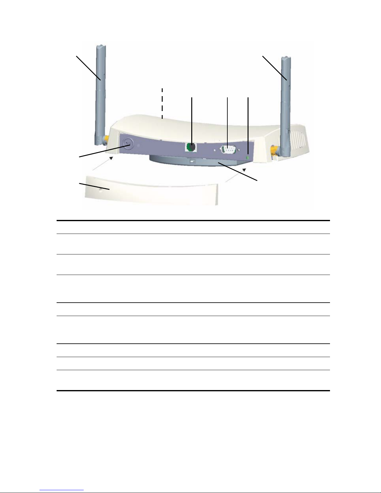
Egenskaper för 3Com trådlös 8760 åtkomstpunkt
1
1
2
43
5
6
78
Funktion Beskrivning
1 Antennanslutningar Två antennanslutningar (RSMA) gör det möjligt att ansluta antenner
som använder 2.4
2 Lysdioder (LED:s) Lysdioderna (LED:s) indikerar ström och aktivitet. Se “Kontrollera LED-
indikatorerna” på sidan 67 för detaljer.
3 Ethernetport Ethernetporten ger en 10/100BASE-TX Ethernetanslutning till en
3Com-switch. Använd en lämplig rak kategori 5-kabel med standard
RJ-45-kontakter för att ansluta dinAccesspunkt
4 Serieport Ger Accesspunkt ett seriellt gränssnitt för felsökning.
5 Återställningsknapp För att återställa tillverkarens inställningar, för in ett spetsigt objekt i
återställningshålet på baksidan av Accesspunkt
sekunder.
6 Kensington lås
7 Avtagbart lock för bakpanel
8 Monteringsfäste Monteringsfästet sitter fast på Accesspunkt och gör det möjligt att
montera enheten på en vägg eller ett tak.
GHz- och 5.3 GHz-banden.
till nätverkets switch.
och håll in i två till fem
62
Page 65

Säkerhetsinformation
Denna utrustning måste installeras i enlighet med lokala och nationella byggregler, lagstadgade
restriktioner samt FCC:s regler. För att skydda både människor och utrustning bör endast proffs på
nätverk installera Accesspunkt
VARNING: Varningarna innehåller anvisningar som du måste följa för din egen
säkerhets skull. Följ alla anvisningar noggrant.
Du måste läsa igenom följande säkerhetsinformation noggrant innan du installerar eller tar bort
enheten.
VARNING: Exceptionell försiktighet måste vidtagas vid installation och borttagning av
enheten.
VARNING: Eluttaget måste vara placerat i närheten av enheten och vara lättåtkomligt.
Du kan endast bryta strömtillförseln till enheten genom att dra ut kontakten ur
eluttaget.
VARNING: Denna enhet uppfyller villkoren för SELV (Safety Extra Low Voltage) enligt
IEC
950 / IEC 60950. Dessa villkor kan endast uppfyllas om utrustningen som enheten
är ansluten till också uppfyller villkoren för SELV.
VARNING: Det finns inga delar inuti enheten som kan bytas ut eller repareras på egen
hand. Om du har något fysiskt problem med enheten som inte kan lösas med hjälp av
felsökningen i denna handbok, kontakta din återförsäljare.
. .
VARNING: Koppla ur strömadaptern innan du flyttar på enheten.
VARNING: RJ-45-portar. Dessa är skyddade RJ-45 datauttag. De kan inte användas
som vanliga traditionella telefonjack eller för att koppla enheten till ett traditionellt PBXsystem eller allmänt telefonnätverk. Anslut endast RJ-45 datakontakter,
nätverkstelefonisystem eller nätverkstelefoner till dessa uttag.
Både skyddade eller oskyddade datakablar med antingen skyddade eller oskyddade
kontakter kan kopplas till dessa datauttag.
VARNING: För att följa FCC:s gränser för strålning genom radiofrekvens (RF), måste
avståndet mellan användare och antenn vara minst 20 cm (8 ”) medan Accesspunkt
används.
Godkända kanaler
Användning av denna produkt är endast tillåten för de kanaler som är godkända av respektive
land. För korrekt installation, välj ditt land från listan med länder.
För att överensstämma med FCC:s begränsningar gällande kanalanvändning är endast kanal 1-11
tillgängliga som standard. Om det är tillåtet att använda kanal 1–13 i ditt land, vänligen besök
3Com:s webbsajt för den senaste programvaruversionen.
www.3Com.com
63
Page 66

1. Packa upp Accesspunkten
Se till att följande finns i förpackningen med Accesspunkt :
• En 3Com Trådlös 8760 11a/b/g PoE Accesspunkt
• Två externa tvåbands antenner (2.4 GHz och 5.3 GHz)
• En PoE (Power over Ethernet) injector
• En Ethernetkabel
• Järnvaror för väggmontering:
• Monteringsfäste (sitter fast på Accesspunkt )
• Två plåtskruvar
• Två gängskruvar
• Två väggankare
• Fyra självhäftande gummifötter (används för installation på plan yta).
• En CD-ROM som innehåller programvara för installationsguiden, användarhandbok samt en
kopia av denna snabbstartguide.
• En garantisedel
2. Förbereda för installation
Det är rekommendabelt att ansluta och kontrollera Ethernetkabeln och lysdioderna (LED:s) innan
man installerar Accesspunkt
monterar och ansluter din Accesspunkt
Funktion Beskrivning
Switchport För att ansluta ditt trådlösa nätverk till ditt kablade nätverk måste du
Kablar Se till att en rak standard Ethernetkabel finns installerad innan du
Strömkrav Ström fås genom en 802.3af Power Over Ethernet (PoE)-kompatibel
MAC-adress Skriv upp accesspunktens MAC-adress på ett säkert ställe innan
på en svåråtkomlig plats. Lägg också märke till följande innan du
:
ha en hubb eller switch ansluten till Accesspunkt
installerar Accesspunkt
Se till att kabeln är högflexibel och att det inte finns något extra hölje
på RJ-45-kontakten som hindrar att kabeln kan routas genom
monteringsfästet.
enhet. A PoE injector är inkluderad.
Accesspunkt
MAC-adressen finns tryckt på baksidan av Accesspunkt . Extra MAC-
adressetiketter levereras med Accesspunkt
installeras på en svåråtkomlig plats.
.
.
.
64
Page 67
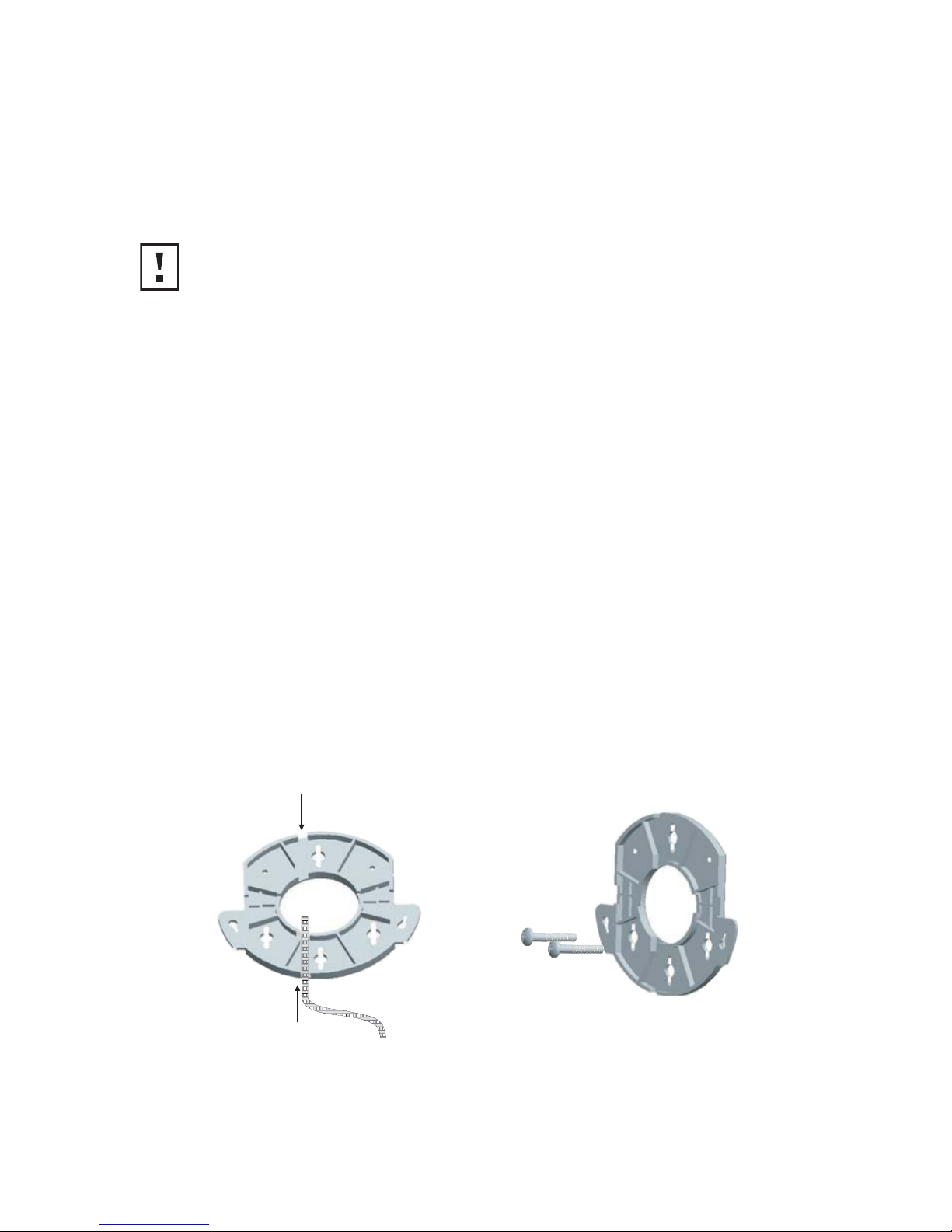
3. Ansluta antennerna
Plocka försiktigt upp de lösa standardantennerna som medföljde din Accesspunkt . Gänga på
varje antenn på en antennanslutning på din Accesspunkt
har startat upp nätverket kan du behöva justera antennerna för att finjustera mottagningen för
den plats där du befinner dig.
För bästa resultat, justera antennerna så att de står i rät vinkel mot golvet och taket.
VARNING: Ta inte på antennernas ändar, särskilt inte efter att de har anslutits till
Accesspunkt
. Detta kan leda till elektrostatisk urladdning som kan skada utrustningen.
och dra åt dem för hand. Efter att du
4. Montera Accesspunkten
Accesspunkten kan monteras på följande typer av ytor:
• Vägg, tak eller kopplingslåda (NEMA-kapsling)
• Bordsyta
Montering på vägg, tak eller kopplingslåda
Använd monteringsfästet som medföljer din Accesspunkt för att installera den på vägg, tak eller i
kopplingslåda. För extra säkerhet, använd den inkluderade låskolven och ett lås (ej inkluderat) för
att låsa fast din Accesspunkt
på hållaren efter att den monterats på en vägg.
Väggmontera Accesspunkt :
1 Routa Ethernetkabeln genom den öppningen i hållaren.
2 Skruva fast monteringsfästet på en vägg, ett tak eller i en kopplingslåda (NEMA-kapsling):
• Vid montering på en fast vägg- eller takyta, använd de två plåtskruvarna.
• Vid montering på gipsvägg, använd de två plåtskruvarna samt de två väggankarna.
• Vid montering i en kopplingslåda (NEMA-kapsling), använd de två gängskruvarna.
Figurerna nedan visar hur en kabel routas genom den stora öppningen i hållaren och sedan
hur hållaren monteras på en vägg.
3 Anslut Ethernetkabeln (för ström- och nätverksanslutning) till porten på framsidan av
Accesspunkt
.
4 Fäst Accesspunkt på monteringsfästet.
65
Page 68
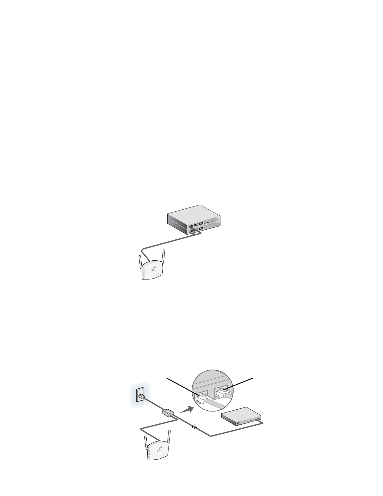
Bordsmontering
3CRWX120695A
Wir
el
ess LAN Swit
ch WX1200
TO ACCESS POINT
TO HUB/SWITCH
För att installera Accesspunkt på en plan yta som till exempel på ett bord eller ett skrivbord:
1 Ta bort skyddet från de fyra gummifötterna och fäst dem på botten av monteringsfästet som
sitter fast på Accesspunkt
.
2 Placera Accesspunkt på bordet.
3 Anslut Ethernetkabeln (för ström- och nätverksanslutning) till porten på framsidan av
Accesspunkt
.
5. Strömanslutning
Accesspunkt kan få ström genom följande metoder:
• Genom Power Over Ethernet (PoE) via LAN genom en 802.3af PoE-kompatibel enhet som till
exempel en switch eller hubb.
• Genom PoE via den PoE injector som medföljer din Accesspunkt .
Power Over Ethernet (PoE) från LAN:et
För att få ström till Accesspunkt genom PoE via en switch eller annan 802.3af-kompatibel enhet,
anslut helt enkelt enhetens nätverkskabel till Accesspunkt
s Ethernetport.
PoE-switch/hubb
Accesspunkt
Power Over Ethernet från en PoE Injector
För att få ström till Accesspunkt genom 3Com PoE Injector (inkluderad), gör följande:
1 Koppla LAN-kabeln från switchen eller hubben till hubb/switch-porten på 3Com PoE Injector
(medföljer Accesspunkt
2 Koppla därefter en LAN-kabel från Ethernetporten på Accesspunkt till den andra porten på
PoE injector.
3 Sätt i PoE Injector i ett jordat eluttag.
Accesspunkt
).
Till Accesspunkt Till switch/hubb
ch WX1200
LAN Swit
ess
Wirel
3CRWX120695A
Switch/hubb
(ej PoE)
66
Page 69
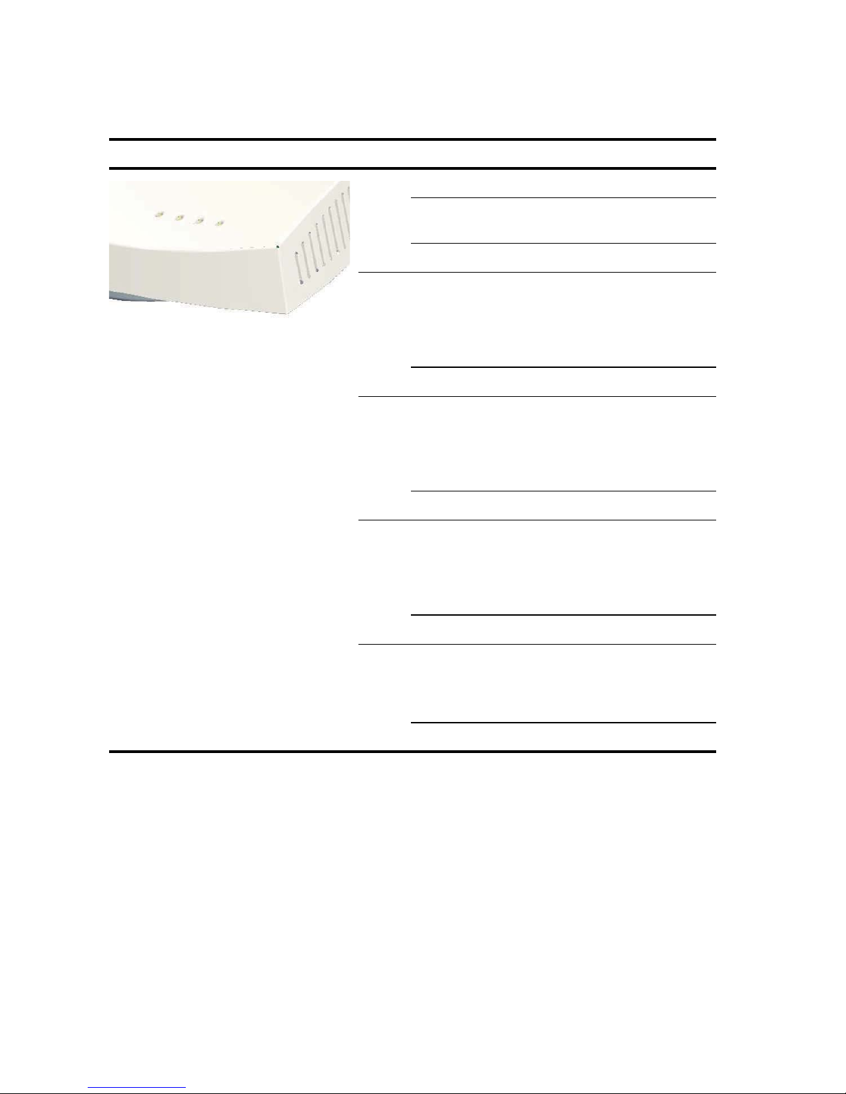
6. Kontrollera LED-indikatorerna
När Accesspunkt ansluts till en strömkälla, indikerar lysdioderna (LED:s) aktivitet enligt följande:
LED Färg Indikerar
Ström Grön Ström på
Gul blinkning anger hårdvarufel eller att
systemet startar upp.
Av Ström av
11a Grön Indikerar att 802.11a 5.0 GHz
trådlösa nätverket är aktiverat. Om
LED-indikatorn blinkar är den trådlösa
länken OK och data sänds eller
mottas.
Av Radion är avstängd
11b/g Grön Indikerar att 802.11g2.4 GHz
trådlösa nätverket är aktiverat. Om
LED-indikatorn blinkar är den trådlösa
länken OK och data sänds eller
mottas.
Av Radion är avstängd
LAN Grön Indikerar att ett 10/100Base-T-
nätverk har upptäckts vid
Ethernetporten. Om LED-indikatorn
blinkar är länken OK och data sänds
eller mottas.
Av Ingen länk
10 Grön Indikerar att ett 10Base-T-nätverk har
upptäckts vid Ethernetporten. Om
LED-indikatorn blinkar är länken OK
och data sänds eller mottas.
Av Ingen länk
7. Installera programvara
Följande program och dokument är inkluderade på 3Com-CD-ROM:en:
• Enhetshanterare för trådlös infrastruktur
• Användarhandbok
• Denna snabbstartguide
Du behöver installera programvaran för Enhetshanteraren för trådlös infrastruktur (WIDMan) på
din dator för att upptäcka och konfigurera Accesspunkt
1 Sätt på datorn.
2 Sätt i 3Coms installations-CD i CD-ROM-enheten.
.
67
Page 70

CD-menyn kommer nu att visas på skärmen. Om denna inte visas kan du köra
inställningsmenyn från Windows Startmeny. Exempel: Start > Kör > d:setup.exe.
3 På menyn klickar du på Hjälpprogram.
4 På nästa skärm dubbelklickar du på 3Com:s Enhetshanterare för trådlös infrastruktur
och klicka sedan på Installera för att installera denna.
5 Följ instruktionerna på skärmen för att utföra installationen. Starta om datorn när du
uppmanas att göra detta.
6 Starta verktyget från Windows Startmeny: välj Start > Program > 3Com Trådlös >
Enhetshanteraren för trådlös infrastruktur.
8. Ansluta till Accesspunkt
Du kan ansluta till Accesspunkt både på nätverk som har en DHCP-server och på nätverk som inte
har en DHCP-server. För att ansluta måste du hitta Accesspunkt
Hitta IP-adressen på nätverk med en DHCP-server
Om ditt nätverk har en DHCP-server, kommer en IP-adress automatiskt att tilldelas Accesspunkt .
Det tar mellan en och två minuter för Accesspunkt
Använda WIDMan (Enhetshanteraren för trådlös infrastruktur) för att hitta Accesspunkt
nätverket och visa dess IP-adress (se
webbläsare eller på en dator som tillhör samma undernät för att visa Accesspunkt s systemstatus
eller för att ändra dess konfiguration.
“Använda WIDMan”). Ange därefter IP-adressen i en
att upptäcka en DHCP-server på nätverket.
s IP-adress.
på
Hitta IP-adressen på nätverk utan en DHCP-server
Om ditt nätverk inte har en DHCP-server, använder Accesspunkt en fabriksinställd standard-IPadress (169.254.2.2).
Använda WIDMan
3Com:s programvara för WIDMan (Enhetshanteraren för trådlös infrastruktur) gör det möjligt att
upptäcka och konfigurera din Accesspunkt
bestämma din Accesspunkt
s IP-adress.
1 Anslut din dator till Accesspunkt antingen direkt eller via nätverket.
2 Starta WIDMan från Windows Startmeny: Start > Program > 3Com Trådlös >
Enhetshanteraren för trådlös infrastruktur.
När din Accesspunkt har upptäckts kommer den att visas på skärmen med Trådlösa nätverk.
3 Klicka för att välja din Accesspunkt och klicka sedan på knappen Egenskaper.
4 Notera din Accesspunkt s IP-adress.
. Följ dessa steg för att använda WIDMan för att
68
Page 71

9. Konfigurera Accesspunkt
För att konfigurera Accesspunkt följer du dessa steg:
1 Anslut till Accesspunkt och leta reda på IP-adressen enligt anvisningarna i “Ansluta till
Accesspunkt”.
2 Starta din dators webbläsare. I adressfältet anger du din Accesspunkt s IP-adress och trycker
på Enter.
3 På Accesspunkt s inloggningsskärm anger du användarnamn och lösenord och klickar på
Logga in.
Användarnamnet och lösenordet är skiftlägeskänsliga.
• Användarnamn: admin
• Lösenord: lösenord
4 Om det är första gången du loggar in på Accesspunkt kommer du att uppmanas att välja i
vilket land du kommer att använda enheten. Välj ditt land från menyn och klicka sedan på
Verkställ.
5 Använd sedan inställningsguiden för att konfigurera din Accesspunkt . Klicka på
Inställningsguiden i menyn till vänster på skärmen.
6 Följ uppmaningarna på skärmen. Använd knapparna Nästa och Tillbaka för att förflytta dig
mellan skärmarna. Klicka på Avsluta när du är klar.
För fullständiga detaljer om hur man använder Enhetshanteraren för trådlös infrastruktur och hur
man konfigurerar din Accesspunkt
Accesspunkt som finns på produkt-CD:n. Uppdateringar till handboken kan hittas på vår
webbsajt:
http://www.3Com.com.
hänvisas till handboken för 3Com Trådlös 8760 11a/b/g PoE
10.Felsökning
För information om felsökning hänvisas till din användarhandbok eller kan du besöka 3Com:s
webbsajt:
http://www.3Com.com.
69
Page 72

70
Page 73

REGULATORY INFORMATION
The 3Com Wireless 8760 Dual-radio 11a/b/g PoE Access Point (WL-546) must be installed and used in strict
accordance with the manufacturer’s instructions as described in the user documentation that comes with the
product.
This
prod
uct con
tains encrypti
Li
cense.
i
This product does not contain any user serviceable components. Any unauthorized product changes or
modifications will invalidate 3Com’s warranty and all applicable regulatory certifications and approvals.
Only antennas specified for your region by 3Com can be used with this product. The use of external amplifiers or
non-3Com antennas may invalidate regulatory certifications and approvals.
This product can be used with the following antennas and accessories:
Item Description Restrictions
— Supplied antenna
3CWE591 3Com 6/8dBi Dual-Band Omni Antenna Must be used with 3CWE586 and one of
3CWE592 3Com 3/4dBi Dual-Band Ceiling Mount
Antenna
3CWE597 3Com 4/6dBi Dual-Band Hallway Antenna Must be used with 3CWE586 and one of
3CWE598 3Com 8/10dBi Dual-Band Panel Antenna Must be used with 3CWE586 and one of
3CWE580 3Com Ultra Low Loss 6-Foot Antenna Cable Must also use 3CWE586. Cannot be used
3CWE581 3Com Ultra Low Loss 20-Foot Antenna Cable Must also use 3CWE586. Cannot be used
3CWE582 3Com Ultra Low Loss 50-Foot Antenna Cable Must also use 3CWE586. Cannot be used
3CWE586 3Com RSMA to SMA 6-inch Antenna Cable Required for all external antennas, except
on. It is
unlawful to export out of the U.S. without obtaining a U.S. Export
the following: 3CWE580, 3CWE581 or
3CWE582.
Must be used with 3CWE586 and one of
the following: 3CWE580, 3CWE581 or
3CWE582.
the following: 3CWE580, 3CWE581 or
3CWE582.
the following: 3CWE580, 3CWE581 or
3CWE582.
with supplied antenna.
with supplied antenna.
with supplied antenna.
that supplied with the Access Point.
CAUTION: EXPOSURE TO RADIO FREQUENCY RADIATION
This device generates and radiates radio-frequency energy. In order to comply with FCC radio-frequency
exposure guidelines for an uncontrolled environment, this equipment must be installed and operated while
maintaining a minimum body to antenna distance of 20 cm (approximately 8 in.).
The installer of this radio equipment must ensure that the antenna is located or pointed such that it does not
emit RF field in excess of Health Canada limits for the general population; consult Safety Code 6, obtainable
from Health Canada’s website www.hc-sc.gc.ca/rpb.
This equipment complies with IC radiation exposure limits set forth for an uncontrolled environment. End users
must follow the specific operating instructions for satisfying RF exposure compliance. This equipment should be
installed and operated with minimum distance 20 cm between the radiator and your body.
This product must maintain a minimum body to antenna distance of 20 cm. Under these conditions this product
will meet the Basic Restriction limits of 1999/519/EC [Council Recommendation of 12 July 1999 on the limitation
of exposure of the general public to electromagnetic fields (0 Hz to 300 GHz)].
71
Page 74

US — RADIO FREQUENCY REQUIREMENTS
This device must not be co-located or operated in conjunction with any other antenna or transmitter.
This device is for indoor use only when using channels 36, 40, 44 or 48 in the 5.15 to 5.25 GHz frequency range.
High power radars are allocated as primary users of the 5.25 to 5.35 GHz and 5.65 to 5.85 GHz bands. These
radar stations can cause interference with and/or damage this device.
USA—FEDERAL COMMUNICATIONS COMMISSION (FCC) EMC COMPLIANCE
This equipment has been tested and found to comply with the limits for a Class B digital device, pursuant to Part
15 of the FCC Rules. These limits are designed to provide reasonable protection against harmful interference in
a residential installation. This equipment generates, uses and can radiate radio frequency energy and, if not
installed and used in accordance with the instructions, may cause harmful interference to radio communications.
However, there is no guarantee that interference will not occur in a particular installation. If this equipment does
cause harmful interference to radio or television reception, which can be determined by turning the equipment
off and on, the user is encouraged to try to correct the interference by one or more of the following measures:
• Reorient or relocate the receiving antenna.
• Increase the separation between the equipment and receiver.
• Connect the equipment into an outlet on a circuit different from that to which the receiver is connected.
• Consult the dealer or an experienced radio/TV technician for help.
The user may find the following booklet prepared by the Federal Communications Commission helpful: The
Interference Handbook. This booklet is available from the U.S. Government Printing Office, Washington, DC
20402. Stock No. 004-000-0034504.
3Com is not responsible for any radio or television interference caused by unauthorized modification of the
devices included with this 3Com Wireless 8760 Dual-radio 11a/b/g PoE Access Point, Model WL-546
(3CRWE876075), or the substitution or attachment of connecting cables and equipment other than specified by
3Com.
The correction of interference caused by such unauthorized modification, substitution or attachment will be the
responsibility of the user.
Changes or modifications not expressly approved by 3Com could void the user's authority to operate this
equipment.
US MANUFACTURER’S FCC DECLARATION OF CONFORMITY
3C
om Corp
35
0 Campus Dr
Marlborough,
(
508)
Date: 1 May 2006
Declares that the Product:
Brand Name: 3Com Corporation
Model Number: WL-546
Equipment Type: Wireless 8760 Dual-radio 11a/b/g PoE Access Point
Co
mplies with Part 15 of
caus
caus
oration
ive
MA 017
323-5000
e har
mful interferen
e undesired operation.
52-3064,
ce, and (2) this
the F
USA
CC rules.
Operation is subject to th
device must accept any interference received,
3Com Wireless 8760 Dual-radio 11a/b/g PoE Access Point
WL-546
e foll
owi
ng two co
nditi
inclu
ons: (
1) this device may not
ding in
terference that may
72
Page 75
INDUSTRY CANADA — RF COMPLIANCE
This device complies with RSS 210 of Industry Canada.
Operation is subject to the following two conditions: (1) this device may not cause interference, and (2) this
device must accept any interference, including interference that may cause undesired operation of this device.
L’utilisation de ce dispositif est autorisée seulement aux conditions suivantes: (1) il ne doit pas produire de
brouillage et (2) l’utilisateur du dispositif doit étre prêt à accepter tout brouillage radioélectrique reçu, même si
ce brouillage est susceptible de compromettre le fonctionnement du dispositif.
The term “IC” before the equipment certification number only signifies that the Industry Canada technical
specifications were met.
To reduce potential radio interference to other users, the antenna type and its gain should be so chosen that the
equivalent isotropically radiated power (EIRP) is not more than that required for successful communication. To
prevent radio interference to the licensed service, this device is intended to be operated indoors and away from
windows to provide maximum shielding. Equipment (or its transmit antenna) that is installed outdoors is subject
to licensing.
Pour empecher que cet appareil cause du brouillage au service faisant l'objet d'une licence, il doit etre utilize a
l'interieur et devrait etre place loin des fenetres afin de Fournier un ecram de blindage maximal. Si le matriel (ou
son antenne d'emission) est installe a l'exterieur, il doit faire l'objet d'une licence.
High power radars are allocated as primary users of the 5.25 to 5.35 GHz and 5.65 to 5.85 GHz bands. These
radar stations can cause interference with and/or damage this device.
This device must not be co-located or operated in conjunction with any other antenna or transmitter.
INDUSTRY CANADA - EMISSIONS COMPLIANCE STATEMENT
This Class B digital apparatus complies with Canadian ICES-003.
Avis de Conformité à la Réglementation d'Industrie Canada
Cet appareil numérique de la classe B est conform à la norme NMB-003 du Canada.
SAFETY COMPLIANCE NOTICE
This device has been tested and certified according to the following safety standards and is intended for use only
in Information Technology Equipment which has been tested to these or other equivalent standards:
• UL Standard 60950-1
• CAN/CSA C22.2 No. 60950-1
• IEC 60950-1
• EN 60950-1
EU COMPLIANCE
This equipment may be operated in
AT BE CY CZ DK EE FI FR
DE GR HU IE IT LV LT LU
MT NL PL PT SK SI ES SE
GB IS LI NO CH BG RO TR
Intended use: IEEE 802.11a/b/g radio LAN device
73
Page 76

NOTE: To ensure product operation is in compliance with local regulations, select the country in which the
product is installed.
Česky [Czech] 3Com Coporation tímto prohlašuje, že tento RLAN device je ve shodě se základ-
ními požadavky a dalšími příslušnými ustanoveními směrnice 1999/5/ES.
Dansk [Danish] Undertegnede 3Com Corporation erklærer herved, at følgende udstyr RLAN
device overholder de væsentlige krav og øvrige relevante krav i direktiv 1999/5/
EF.
Deutsch [German] Hiermit erklärt 3Com Corporation, dass sich das Gerät RLAN device in Überein-
stimmung mit den grundlegenden Anforderungen und den übrigen einschlägigen
Bestimmungen der Richtlinie 1999/5/EG befindet.
Eesti [Estonian] Käesolevaga kinnitab 3Com Corporation seadme RLAN device vastavust direkti-
ivi 1999/5/EÜ põhinõuetele ja nimetatud direktiivist tulenevatele teistele asjakohastele sätetele.
English Hereby, 3Com Corporation, declares that this RLAN device is in compliance with
the essential requirements and other relevant provisions of Directive 1999/5/EC.
Español [Spanish] Por medio de la presente 3Com Corporation declara que el RLAN device cum-
ple con los requisitos esenciales y cualesquiera otras disposiciones aplicables o
exigibles de la Directiva 1999/5/CE.
Ελληνική [Greek] ΜΕ ΤΗΝ ΠΑΡΟΥΣΑ 3Com Corporation ΔΗΛΩΝΕΙ ΟΤΙ RLAN device
ΣΥΜΜΟΡΦΩΝΕΤΑΙ ΠΡΟΣ ΤΙΣ ΟΥΣΙΩΔΕΙΣ ΑΠΑΙΤΗΣΕΙΣ ΚΑΙ ΤΙΣ ΛΟΙΠΕΣ
ΣΧΕΤΙΚΕΣ ΔΙΑΤΑΞΕΙΣ ΤΗΣ ΟΔΗΓΙΑΣ 1999/5/ΕΚ.
Français [French] Par la présente 3Com Corporation déclare que l'appareil RLAN device est con-
forme aux exigences essentielles et aux autres dispositions pertinentes de la
directive 1999/5/CE.
Italiano [Italian] Con la presente 3Com Corporation dichiara che questo RLAN device è con-
forme ai requisiti essenziali ed alle altre disposizioni pertinenti stabilite dalla
direttiva 1999/5/CE.
Latviski [Latvian] Ar šo 3Com Corporation deklarē, ka RLAN device atbilst Direktīvas 1999/5/EK
būtiskajām prasībā
Lietuvių [Lithuanian] Šiuo 3Com Corporation deklaruoja, kad šis RLAN device atitinka esminius reika-
lavimus ir kitas 1999/5/EB Direktyvos nuostatas.
Nederlands [Dutch] Hierbij verklaart 3Com Corporation dat het toestel RLAN device in overeenstem-
ming is met de essentiële eisen en de andere relevante bepalingen van richtlijn
1999/5/EG.
Malti [Maltese] Hawnhekk, 3Com Corporation, jiddikjara li dan RLAN device jikkonforma mal-
htigijiet essenzjali u ma provvedimenti ohrajn relevanti li hemm fid-Dirrettiva
1999/5/EC.
Magyar [Hungarian] Alulírott, 3Com Corporation nyilatkozom, hogy a RLAN device megfelel a vonat-
kozó alapvetõ követelményeknek és az 1999/5/EC irányelv egyéb elõírásainak.
Polski [Polish] Niniejszym 3Com Corporation oświadcza, że RLAN device jest zgodny z zasad-
niczymi wymogami oraz pozostałymi stosownymi postanowieniami Dyrektywy
1999/5/EC.
Português
[Portuguese]
Slovensko [Slovenian] 3Com Corporation izjavlja, da je ta RLAN device v skladu z bistvenimi zahtevami
Slovensky [Slovak] 3Com Corporation týmto vyhlasuje, že RLAN device spĺňa základné požiadavky
Suomi [Finnish] 3Com Corporation vakuuttaa täten että RLAN device tyyppinen laite on direkti-
3Com Corporation declara que este RLAN device está conforme com os requisitos essenciais e outras disposições da Directiva 1999/5/CE.
in ostalimi relevantnimi določili direktive 1999/5/ES.
a všetky príslušné ustanovenia Smernice 1999/5/ES.
ivin 1999/5/EY oleellisten vaatimusten ja sitä koskevien direktiivin muiden
ehtojen mukainen.
m un citiem ar to saistītajiem noteikumiem.
A copy of the signed Declaration of Conformity can be downloaded from the Product Support web page for the
3Com Wireless 8760 Dual-radio 11a/b/g PoE Access Point, Model WL-546 (3CRWE876075) at http://
www.3com.com. Also available at http://support.3com.com/doc/WL-546_EU_DOC.pdf
74
Page 77
EU - RESTRICTIONS FOR USE IN THE 2.4 GHZ BAND
This device may be operated indoors or outdoors in all countries of the European Community using the 2.4 GHz
band: Channels 1–13, except where noted below.
•In Italy the end-user must apply for a license from the national spectrum authority to operate this device
outdoors.
•In Belgium outdoor operation is only permitted using the 2.46 – 2.4835 GHz band: Channel 13.
•In France outdoor operation is only permitted using the 2.4 – 2.454 GHz band: Channels 1 – 7.
EU - RESTRICTIONS FOR USE IN THE 5 GHZ BAND
Allowed Frequency Bands Allowed Channel Numbers Countries
5.15–5.35 GHz 36, 40, 44, 48, 52, 56, 60, 64 Czech Republic, France
5.15–5.35 & 5.470–5.725 GHz 36, 40, 44, 48, 52, 56, 60, 64, 100,
104, 108, 112, 116, 120, 124, 128,
132, 136, 140
• This device may be not be operated outdoors when using the bands 5150–5350 MHz (Channels 36, 40, 44,
48, 52, 56, 50, 64).
• In Italy the end-user must apply for a license from the national spectrum authority to operate this device
outdoors.
• To remain in conformance with European spectrum usage laws for Wireless LAN operation, the above 5 GHz
channel limitations apply. The user should check the current channel of operation. If operation is occurring
outside of the allowable frequencies as listed above, the user must cease operating the Access Point at that
location and correct the configuration of the channels used before resuming operation.
• The 5 GHz Turbo mode feature is not allowed for operation in any European Community country.
• This device must be used with the radar detection feature required for European Community operation in the
5 GHz bands. This device will avoid operating on a channel occupied by any radar system in the area. The
presence of nearby radar operation may result in temporary interruption in communications of this device.
The Access Point's radar detection feature will automatically restart operation on a channel free of radar. You
may consult with the local technical support staff responsible for the wireless network to ensure the Access
Point device(s) are properly configured for European Community operation.
Austria, Belgium, Bulgaria, Cyprus,
Denmark, Estonia, Finland,
Germany, Greece, Hungary,
Iceland, Ireland, Italy, Latvia,
Liechtenstein, Lithuania,
Luxembourg, Malta, Netherlands,
Norway, Poland, Portugal, Slovakia,
Slovenia, Spain, Sweden,
Switzerland, U.K.
BRAZIL RF COMPLIANCE
Este equipamento opera em caráter secundário, isto é, nao tem direito a proteçao contra interferencia
prejudicial, mesmo de estaçoes do mesmo tipo, e nao causar interferencia a sistema operando em caráter
primário.
KOREA RF COMPLIANCE
This device may cause radio interference during its operation. Therefore service in relation to human life security
is not available.
75
Page 78

76
 Loading...