

Page 1
Quick Start Guide
Wireless LAN Access Point 7250
3CRWE725075
The 3Com Wireless LAN Access Point 7250 offers enterprise network standard based security and complete
centralized management, with flexible and expansive connectivity and scalability. It extends networks and
boosts productivity for centrally managed enterprises requiring scalable security solutions.
NOTE: This product must be installed by a professional technician/installer.
R
a
d
io
E
th
e
rn
P
o
e
w
t
e
r
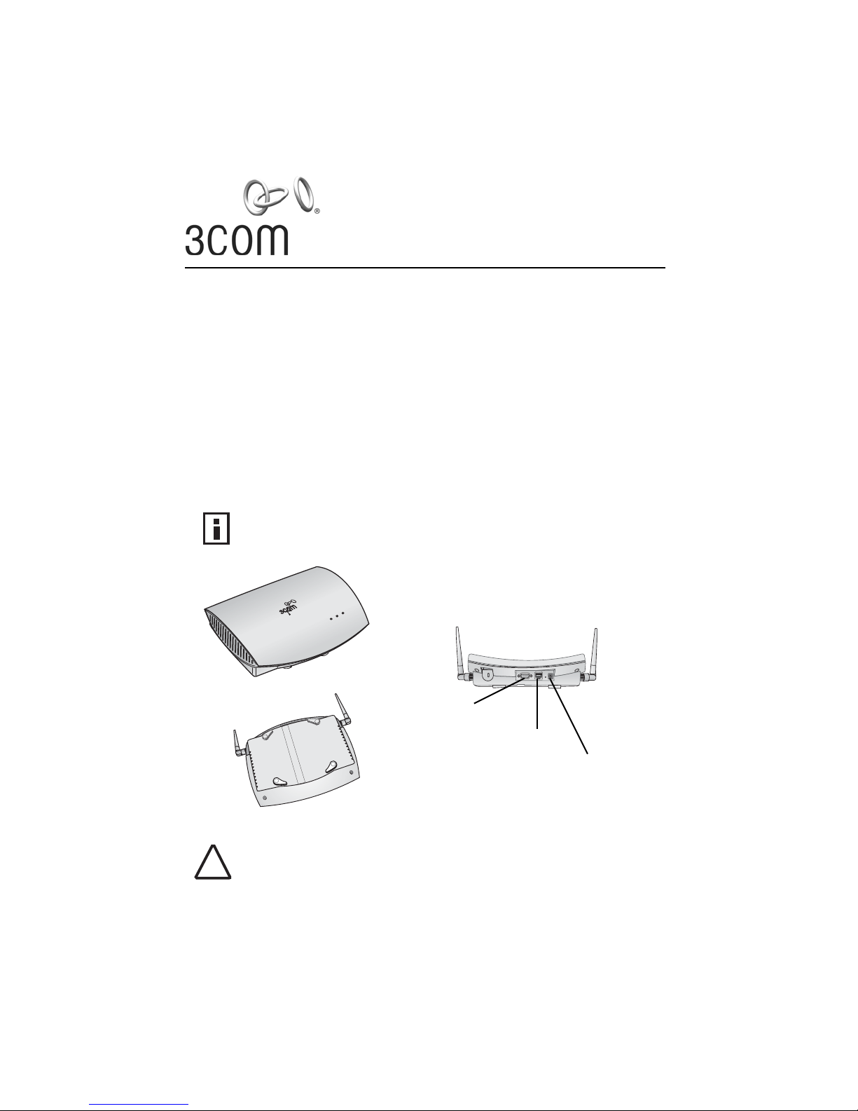
Access Point 7250 - Front
Console port
Ethernet port
Power supply
Access Point 7250 - Back
CAUTION: Do not connect a telephone cable into the Ethernet port; doing so can cause serious
damage to the access point.
!
1
Page 2

1 Before You Start
■ Make sure that you have the following items ready for the installation:
■ 3Com Access Point 7250
■ Standard detachable antennas
■ Power supply
■ Power cord
■ 3Com installation CD
■ Ethernet category 5 straight cables (8-wire)
■ For wall-mount installations you will need the following items:
Mounting plate
Mounting screws
Plastic anchors for drywall mounting
■ To use the Web configuration management system, you need a computer running one of the
following operating systems and one of the following browsers:
■ Operating Systems: Windows 98, Windows ME, Windows NT 4.0 (with the latest
service pack), Windows 2000, or Windows XP.
■ Browsers: Internet Explorer 5.0 or later. (Internet Explorer 5.5 is available on the
installation CD.)
2 Prepare for Installation
It is advisable to connect the power and check the Ethernet cables and LEDs before installing the unit in a hardto-reach location.
1 Observe the following power requirements:
The access point complies with the IEEE 802.3af power-over-Ethernet standard. It receives
power over category 5 straight cable. Installation requires the use of either the 3Com power
supply provided or IEEE 802.3af compliant power supply equipment (output power rated
48 V DC @ 350 mA maximum). Such equipment must be safety certified according to UL,
CSA, IEC or other applicable national or international safety requirements for the country of
use. All references to the power supply refer to equipment that meets these requirements.
Because the power supply plug is the only means of disconnecting the access point from
power, make sure the power outlet is accessible.
The power supply can be located indoors at any point between the access point and the LAN
access port where an accessible power outlet exists.
2 Decide where to place the access point.
■ Mounted on a wall on a stud (or other hard surface)
■ Mounted on to drywall
■ Placed on a flat surface
The location should be elevated and centrally located relative to users on your network. Ceiling mounting is not
recommended.
NOTE: Regulatory restrictions dictate that when the access point is operational a minimum bodyto-antenna distance of 1 meter (3 feet) must be maintained.
3 Record the access point MAC address and serial number in a safe place before the access
point is installed in a hard-to-reach location. The MAC address is printed on the back of the
access point housing.
4 Carefully unpack the standard detachable antennas. Screw the antennas on to the SMA
connectors and hand-tighten them. After network startup, you may need to adjust the antennas
to fine-tune coverage in your area.
2
Page 3
CAUTION: Do not handle the antenna tips, especially after they are connected to the access
point, as this could lead to electrostatic discharge (ESD), which could damage the equipment.
!
The installation CD includes the User Guide, which contains more detailed information on planning, installing
and configuring the device. Additional tools and utilities are provided to assist with the management of your
network. See “Documentation and Software Utilities” on page 7 for instructions.
3 Connect the Power
The access point complies with the IEEE 802.3af power-over-Ethernet standard. It receives power over a
standard category 5 straight (8-wire) Ethernet cable. There are three ways to supply power to the access point:
■ Use the AC adapter included with the Access Point 7250.
■ Use an optional 3Com Integrated Power-over-Ethernet power supply. In this case, you need to
supply a second Ethernet cable to connect to the wired LAN.
■ Connect the access point directly to your own Power-over-Ethernet hub or switch, which
must also comply with the IEEE 802.3af standard.
Using the Included AC Adapter
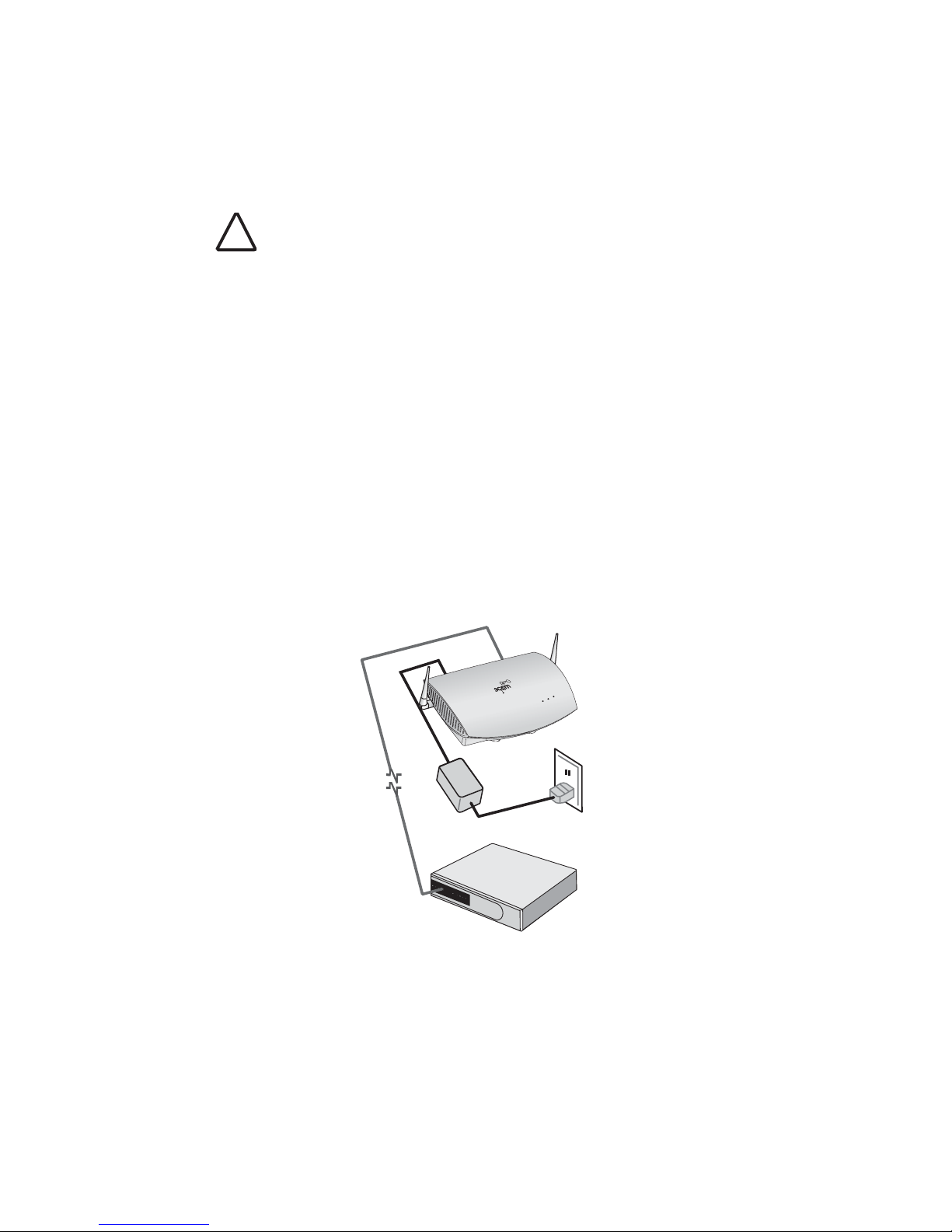
The power supply included with the Access Point 7250 is an AC adapter. Follow these steps to connect the AC
adapter:
1 Connect the power cord to the power supply and plug the cord into a power outlet.
2 Connect the DC power into the Access Point 7250.
Using the included AC Adapter
R
ad
io
Et
h
erne
Po
w
t
e
r
3
Page 4
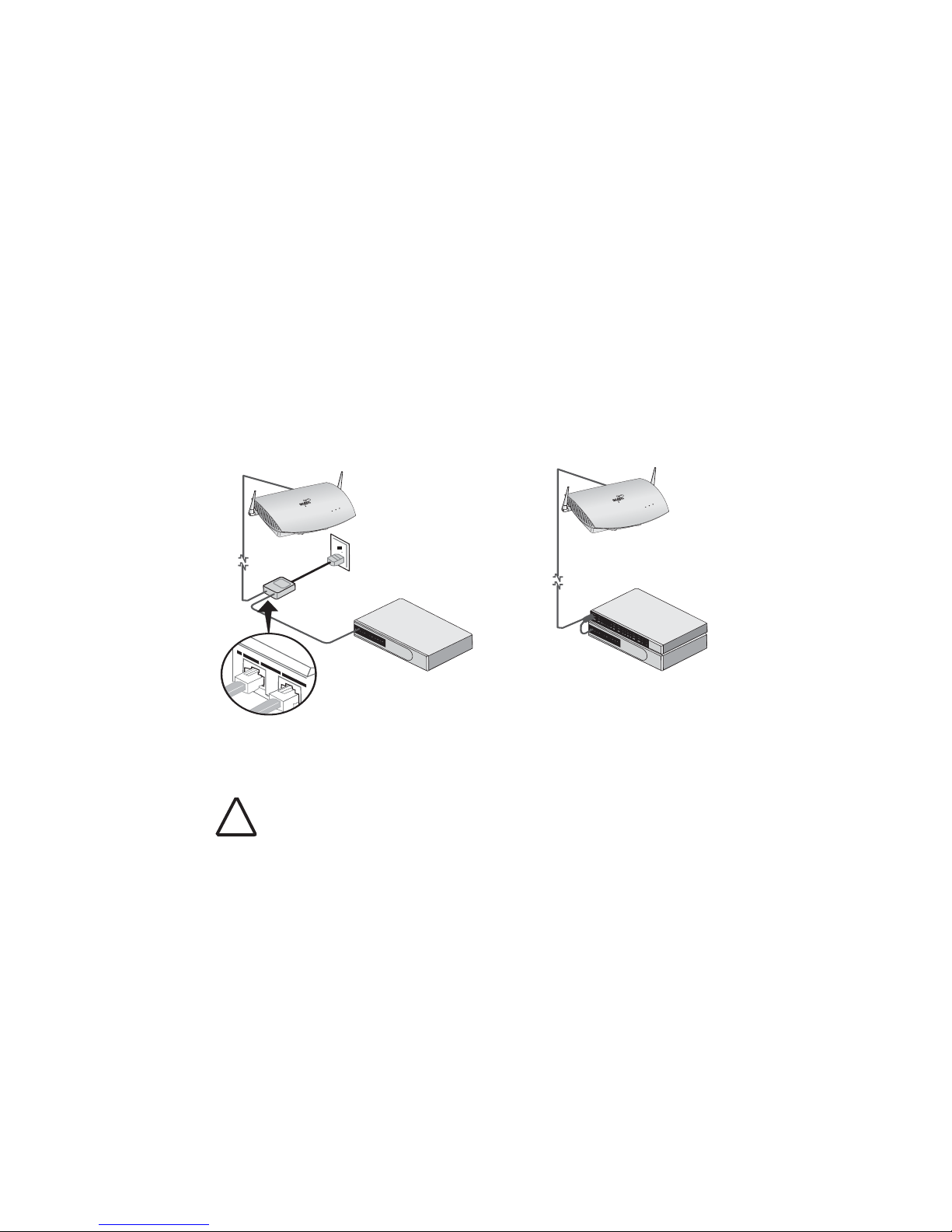
Using An Optional Power-Over-Ethernet Injector
The Power-Over-Ethernet Injector can be located at any point between the access point and the LAN access
port, wherever a convenient power outlet exists. If you supply your own Ethernet cable for connecting power,
be sure that it is standard category 5 straight-through (8-wire) cable that has not been altered in any way. Use of
nonstandard cable could damage the access point.
Refer to the illustration below, and follow these steps:
1 Connect one end of the Ethernet cable to the Ethernet port on the access point.
2 Connect the other end of the Ethernet cable to the port labeled To Access Point on the power
supply.
3 Connect the power cord to the power supply and plug the cord into a power outlet.
4 To link the access point to your Ethernet network, plug one end of another Ethernet cable into
the port labeled To Hub/Switch on the power supply, and plug the other end into a LAN port
(on a hub or in a wall).
R
a
d
i
E
o
t
h
e
P
r
o
n
w
R
a
d
i
E
o
t
h
e
P
r
o
n
w
e
t
e
r
e
t
e
r
Using an Optional Power-over-Ethernet Injector
Using an Optional Power-over-Ethernet
LAN port
CAUTION: To avoid damaging network equipment, make sure that the cables are connected
from access point to power supply to LAN as shown and described above.
!
4
Page 5
4 Check the LEDs
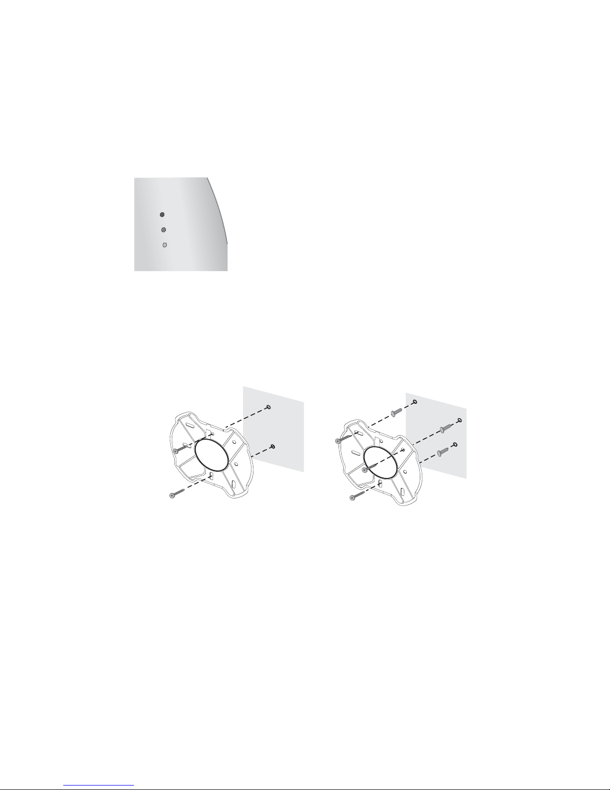
When power is connected, the access point LEDs light up. The illustration and the following table describe the
LEDs and their functions.
Name Description
Radio LED blinks red to indicate radio activity. Faster blinking
indicates more activity.
RADIO
ETHERNET
POWER
Ethernet LED lights yellow when 10 Mbps Ethernet link is
established. LED lights green when 100 Mbps Ethernet
link is established. LED blinks to indicate activity on the
Ethernet. Faster blinking indicates more activity.
Power LED lights green when operational code is running. LED
lights yellow when a power-on fault occurs.
5 Wall Mount Installation
1 Install the mounting plate as shown in the following illustration, on either a stud (or other
hard wall surface), or onto drywall.
If installing into a stud or other
secure vertical surface, use 2 screws.
If installing into drywall, use 3 plastic
anchors and 3 screws
.
B
A
■ Allow for a clearance of at least 25 cm (10 inches) between the ceiling and the top of the
B
A
mounting plate.
■ Orient the bracket with the letter “B” at the top of the bracket.
■ For installation on a wall stud, install the top screw into the stud, as shown at left in the
illustration, and then vertically align the mounting plate before installing the
bottom screw.
■ For installation on to drywall, mark three screw holes using the mounting plate as a
template for vertical alignment, as shown at right in the illustration above.
■ Use a 5-mm (3/16-in.) drill bit if using the plastic anchors provided.
■ For drywall mounts, you can route the cable through the center opening for a seamless
appearance using one of the methods illustrated below. Alternatively, you can simply
attach the Ethernet cable to the top of the unit, allowing it to trail along the wall.
5
Page 6
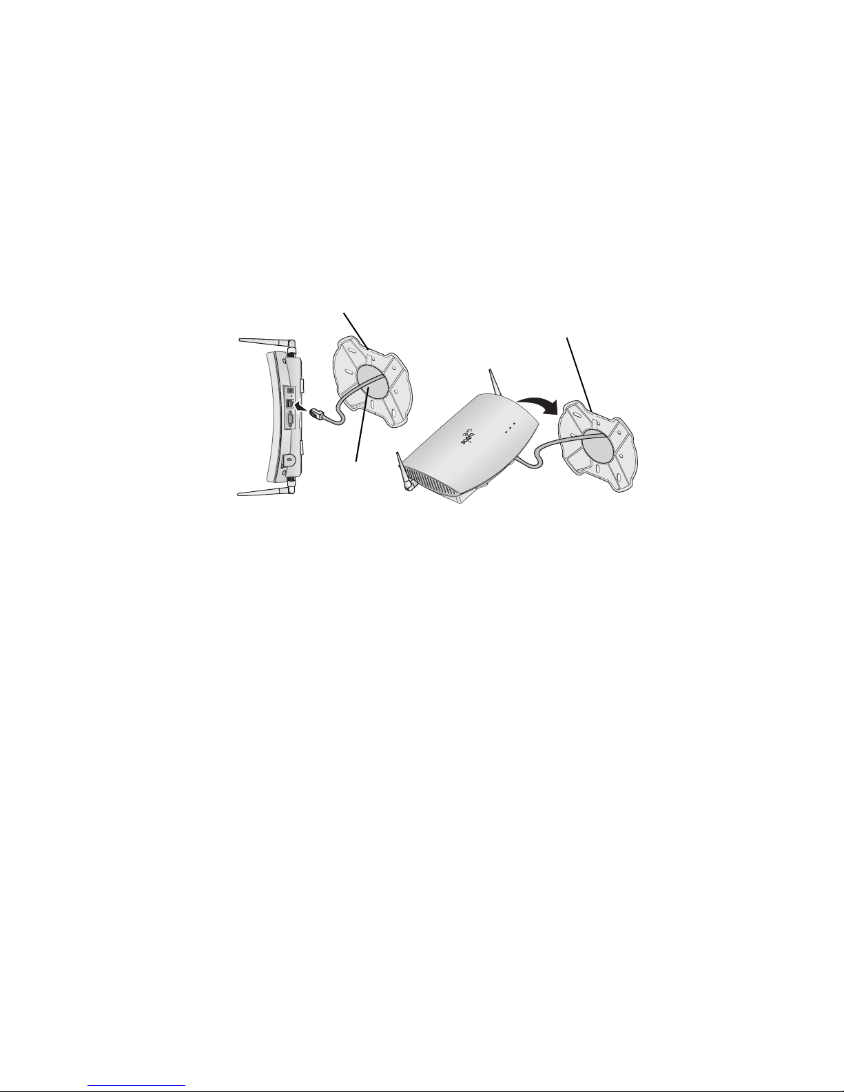
■ If you have routed the Ethernet cable through the center opening, secure the cable on the
hook located on the mounting plate as shown in the illustration below.
2 Connect the Ethernet cable to the Ethernet port on the access point.
3 Connect the power cable to the power port on the rear panel of the access point.
4 Position the access point at an angle to the mounting plate bayonet connection and turn the
unit clockwise until it snaps into place, as shown below.
Top opening
Hook for securing
the cable
B
A
R
a
d
io
E
th
e
rn
e
t
P
o
w
e
r
Center opening
Align with mounting plate
and rotate clockwise to lock
6 Flat Surface Installation
1 Find a clean and dry surface that is elevated enough to provide good reception and coverage
for the network. Do not place the access point on a metal surface.
2 Make sure to choose a location where the access point will not be disturbed.
3 Connect the Ethernet cable into the Ethernet port.
4 Connect the power cable to the power port on the rear panel of the access point.
5 Set the access point down on a flat, level surface.
B
A
6
Page 7
7 Antenna Adjustment
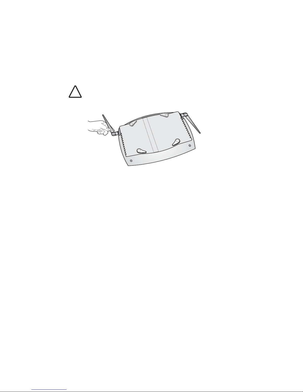
Position the antennas so that they turn away from the access point at approximately a 45-degree angle. Your
particular location might require additional antenna adjustment.
CAUTION: Do not handle the antenna tips, especially after they are connected to the access
point, as this could lead to electrostatic discharge (ESD), which could damage the equipment.
!
8 Documentation and Software Utilities
The installation CD includes documentation and software utilities to help you set up and administer the wireless
components of your network. To view product documentation, select View the Documentation from the CD
Startup Menu and then select the item you wish to view. To install utilities, select Tools and Utilities from the
CD Startup Menu. Select the items you wish to install and follow the onscreen instructions. The software Tools
and Utilities include:
■ 3Com Wireless Infrastructure Device Manager. Use this tool to discover access points and
select devices for administrative changes. Uninstall any previous versions before installing
this version.
■ 3Com 3CDaemon Server Tool. This tool can act in four different capacities:
■ As a TFTP Server, necessary for firmware upgrades, and backup and restore functions.
Use this option if you do not have a TFTP server set up.
■ As a SysLog Server, which is necessary to view SysLog messages.
■ As an optional TFTP Client.
■ As an optional FTP Server.
■ 3Com Network Supervisor. The 3Com Network Supervisor (3NS) graphically discovers,
maps, and displays network links and IP devices, including 3Com wireless access points. It is
not required for access point management.
■ 3Com Site Survey Tool. This utility assists in selecting the best location for your access point
before installing the device permanently. Use the Site Survey Tool to determine if the
intended mounting locations will provide adequate coverage with good signal strength and
quality.
■ Internet Explorer 5.5. This browser is included for those who do not have a
suitable browser.
7
Page 8

9 Configuration Notes
■ For a new access point installation, the default WLAN Service Area (ESSID) is 3Com and no
security is set. Unless it detects a DHCP server on the network, the access point uses Auto IP
to assign an IP address of the form 169.254.2.1.
■ Use the 3Com Wireless Infrastructure Device Manager to locate 3Com Wireless LAN devices
and launch their configurations. When installing the device manager, make sure the computer
is connected to the same network as the device to be configured. The default login is “admin”
and there is no password. After installing and launching the device manager, select the device
to be configured from network tree and click Configure to launch the configuration Web
interface. Refer to the Access Point 7250 User Guide (included on the installation CD) for
detailed information and instructions on locating and configuring the access point.
■ The first time you connect to this device, you will need to specify how the device obtains its
IP address; for most installations we recommend that you select “Obtain the setting
automatically from a DHCP server.” For more information, see your network administrator.
■ Once you have logged onto the device, we strongly recommend changing the default
password. You can find password settings in the administration menu.
■ If you experience difficulty with the installation, see the Troubleshooting section of the
User Guide.
For the latest information, see the 3Com Corporation World Wide Web site: http://www.3com.com/.
Copyright © 2003 3Com Corporation. All rights reserved. 3Com, the 3Com logo, and SuperStack are registered
trademarks of 3Com Corporation. All other company and product names may be trademarks of the respective
companies with which they are associated.
09-2340-000 Rev AA
Published December 2003
8
 Loading...