

Page 1

NT3BB-1PWN
Quick Installation Guide
Page 2

NT3BB-1PWN Error! Use the Home tab to apply 标题 to the text that
you want to appear here.
1 Introduction
The NT3BB-1PWN is an ADSL access device that supports multiple line modes.
It provides one 10/100Base-T Ethernet interfaces at the user end, and
high-speed ADSL broadband connection to the Internet or Intranet for high-end
users such as net cafes and office users with a downlink of 24 Mbps and uplink of
1 Mbps.
As a WLAN AP or WLAN router, the device supports WLAN access to the
Internet, complying with the IEEE 802.11b/g/n specifications, WEP, WPA and
WPA2 security specifications.
2 System Requirements
Recommended system requirements are as follows:
A 10/100 base-T Ethernet card is installed on your PC
A hub or switch (connected to several PCs through one of Ethernet
interfaces on the device)
Operating system: Windows 98 SE, Windows 2000, Windows ME,
Windows XP, Windows Vista, Windows 7
Internet Explorer V5.0 or higher, Netscape V4.0 or higher, or Firefox 1.5 or
higher
3 Hardware Installation
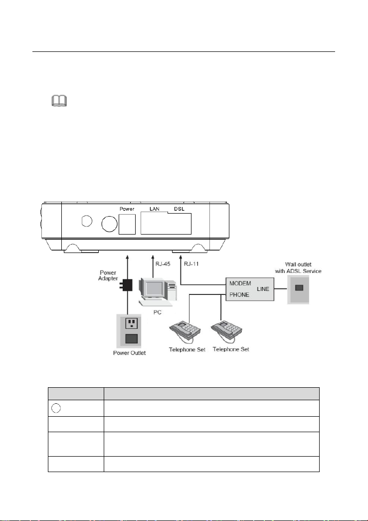
Step 1 Connect the DSL interface of the device and the Modem interface of
the splitter through a telephone cable. Connect the phone to the
Phone interface of the splitter through a cable. Connect the incoming
line to the Line interface of the splitter.
The splitter has three interfaces:
Line: Connect to a wall phone jack (RJ-11 jack).
Modem: Connect to the ADSL jack of the device.
Phone: Connect to a telephone set.
2
Page 3
NT3BB-1PWN Error! Use the Home tab to apply 标题 to the text that
Items
Description
Power switch for powering on/off the device.
Power
Power interface for connecting to the power adapter.
LAN
RJ-45 interface for connecting to the Ethernet interface of
PC or other Ethernet devices through the Ethernet cable.
DSL
RJ-11 interface for connecting to the ADSL interface or a
you want to appear here.
Step 2 Connect the LAN interface of the device to the network card of the PC
through an Ethernet cable (MDI/MDIX).
Note:
Use twisted-pair cables to connect with the hub or switch.
Step 3 Plug one end of the power adapter to the wall outlet and connect the
other end to the Power interface of the device.
The following is the application diagram for the connection of the router, PC,
splitter and telephones.
The following table describes the interfaces and buttons of the device.
3
Page 4

NT3BB-1PWN Error! Use the Home tab to apply 标题 to the text that
Items
Description
splitter through the telephone cable.
WLAN
Press the button gently and let go after 2 seconds to enable
WLAN function.
Reset
Reset to the factory defaults. To reset to the factory
defaults, keep the device powered on and push a paper clip
in to the hole for over 3 seconds. Then release it, the
configuration is reset to the factory defaults.
you want to appear here.
4 Web Configuration
4.1 Configuring IP Address of Network Card
Configure TCP/IP properties of your network card to Obtain an IP address
automatically from modem, or set the IP address of the computer with the
same network mask of the modem.
For example, if the IP address of Router is 10.0.0.2/255.255.255.0, you can set
the IP address of the computer to 10.0.0.x/255.255.255.0. The range for x is from
3 to 254.
4.2 Accessing the Router
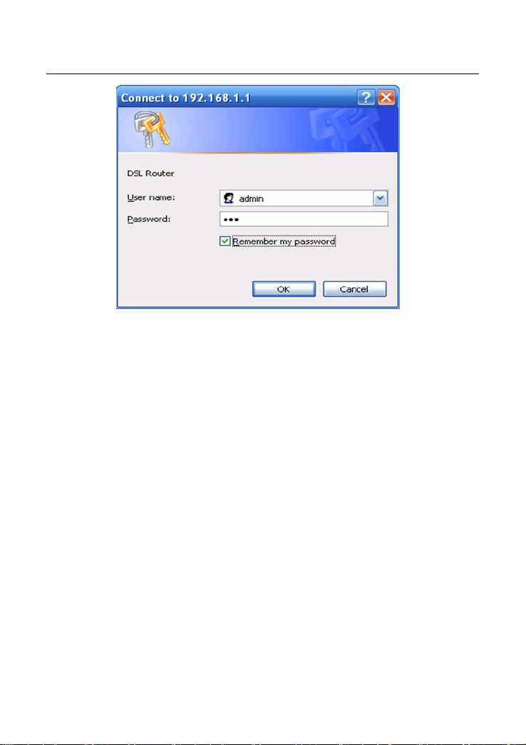
Step 1 Open the Internet Explorer (IE) browser and enter http://192.168.1.1.
Step 2 In the Login page that is displayed, enter the username and password.
The username and password of the admin user are admin and 3bb.
4
Page 5
NT3BB-1PWN Error! Use the Home tab to apply 标题 to the text that
you want to appear here.
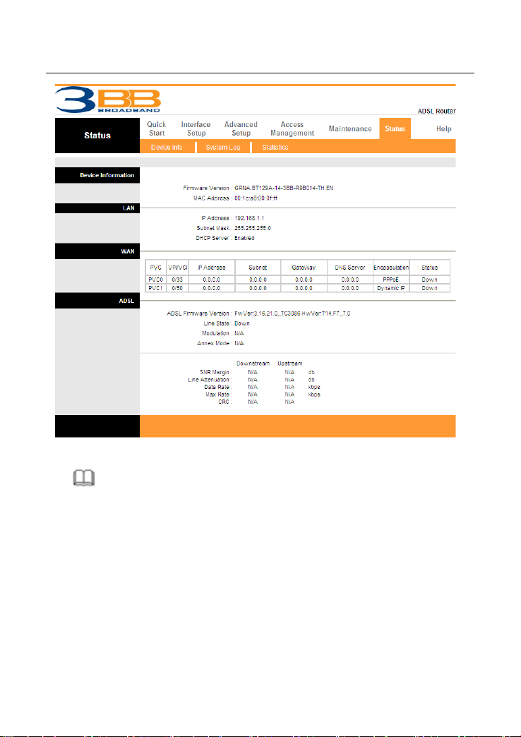
After logging in to the DSL router as a super user, you will see the following
interface. You can check, configure and modify all the settings.
5
Page 6
NT3BB-1PWN Error! Use the Home tab to apply 标题 to the text that
you want to appear here.
Note:
In the Web configuration page, the settings can be saved permanently.
4.3 Internet Settings
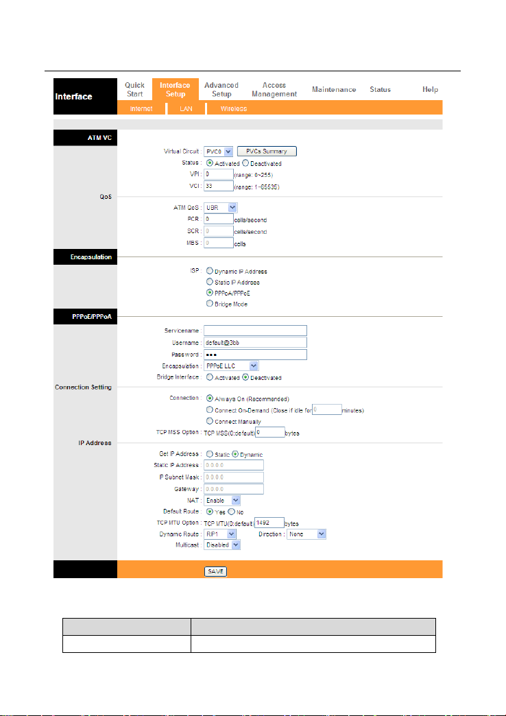
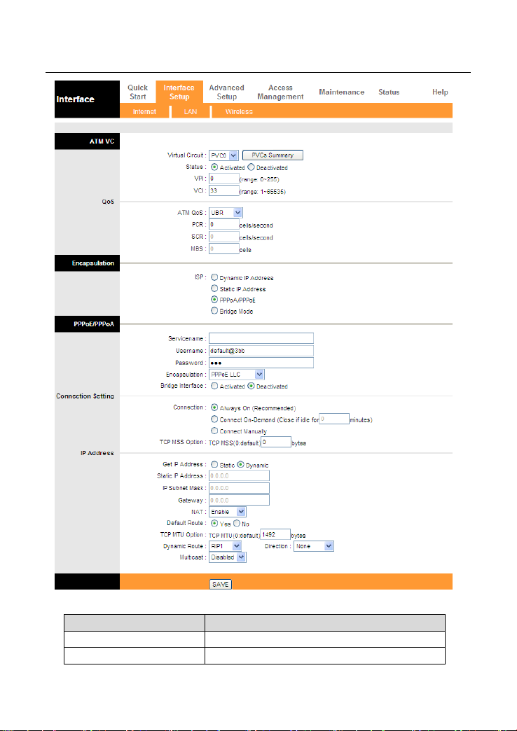
Choose Interface Setup > Internet. Click Internet pane, the page shown in the
following figure appears. In this page, you can configure WAN interface of your
router.
6
Page 7
NT3BB-1PWN Error! Use the Home tab to apply 标题 to the text that
Field
Description
Virtual Circuit
You can select a virtual circuit from the
you want to appear here.
The following table describes the parameters of this page:
7
Page 8

NT3BB-1PWN Error! Use the Home tab to apply 标题 to the text that
Field
Description
drop-list. Click PVCs Summary you can view
eight PVCs (from PVC0 to PVC7), and only
PVC0 status is activated by default.
Status
You can select Activated or Deactivated for
currently selected virtual circuit.
VPI
The virtual path between two points in an ATM
network, ranging from 0 to 255.
VCI
The virtual channel between two points in an
ATM network, ranging from 1 to 65535.
ATM QoS
Select the Quality of Service types for this
Virtual Circuit. The ATM QoS types include
CBR (Constant Bit Rate), VBR (Variable Bit
Rate) and UBR (Unspecified Bit Rate). These
QoS types are all controlled by the parameters
specified below, including PCR, SCR and MBS.
You can choose CBR, UBR, rtVBR, or nrtVBR.
PCR
Peak cell rate (PCR) is the maximum rate at
which cells can be transmitted along a
connection in the ATM network.
SCR
Sustain cell rate (SCR) is the maximum rate
that traffic can pass over PVC without the risk
of cell loss.
MBS
Maximum burst size (MBS) is the maximum
number of cells that can be transmitted at the
PCR.
ISP
You can choose Dynamic IP Address, Static
IP Address, PPPoA/PPPoE or Bridge Mode.
you want to appear here.
Select PPPoA/PPPoE in the ISP encapsulation if your ISP requires you to use a
PPPoE connection. This option is typically used for DSL services. Select
Dynamic PPPoE to obtain an IP address automatically for your PPPoE
connection. Select Static PPPoE to use a static IP address for your PPPoE
connection. Please enter the information accordingly.
8
Page 9
NT3BB-1PWN Error! Use the Home tab to apply 标题 to the text that
Field
Description
Servicename
You can set the service name.
Username
Enter the username for PPPoE dial-up, which
you want to appear here.
The following table describes the parameters of this page:
9
Page 10

NT3BB-1PWN Error! Use the Home tab to apply 标题 to the text that
Field
Description
is provided by your ISP.
Password
Enter the password for PPPoE dial-up, which
is provided by your ISP.
Encapsulation
You can choose PPPoE LLC, PPPoE
VC-Mux, PPPoA LLC or PPPoA VC-Mux.
Bridge Interface
You can choose Activated or Deactivated.
Connection
You can choose Always On
(Recommended), Connect On-Demand or
Connect Manually.
TCP MSS Option
You can set a tcp mss value. The range is
from 100 to 1452. The default is 0.
Get IP Address
You can choose Static or Dynamic.
Static IP Address
You can enter the ip address for dial-up,
which is provided by your ISP.
IP Subnet Mask
You can enter the ip subnet mask for dial-up,
which is provided by your ISP.
Gateway
You can enter the gateway ip for dial-up,
which is provided by your ISP.
NAT
Select it to enable Network Address
Translation (NAT) function. If you do not
select it and you want to access the Internet
normally, you must add a route on the uplink
equipment. Otherwise, the access to the
Internet fails. Normally, it is enabled.
Default Route
You can enable or disable default route.
TCP MTU Option
You can set a TCP MTU value. The range is
from 100 to 1500. The default is 0.
Dynamic Route
You can select RIP1, RIP2-B or RIP2-M.
Direction
You can select None, Both, IN Only or OUT
Only.
Multicast
IGMP (Internet Group Multicast Protocol) is a
session-layer protocol used to establish
membership in a multicast group. The ADSL
Router supports IGMP version 1 (IGMP-v1),
IGMP-v2 and IGMP-v3 .Select Disabled to
you want to appear here.
10
Page 11

NT3BB-1PWN Error! Use the Home tab to apply 标题 to the text that
Field
Description
disable it.
you want to appear here.
After finishing, click SAVE to apply the settings of this PVC.
4.4 Wireless Settings
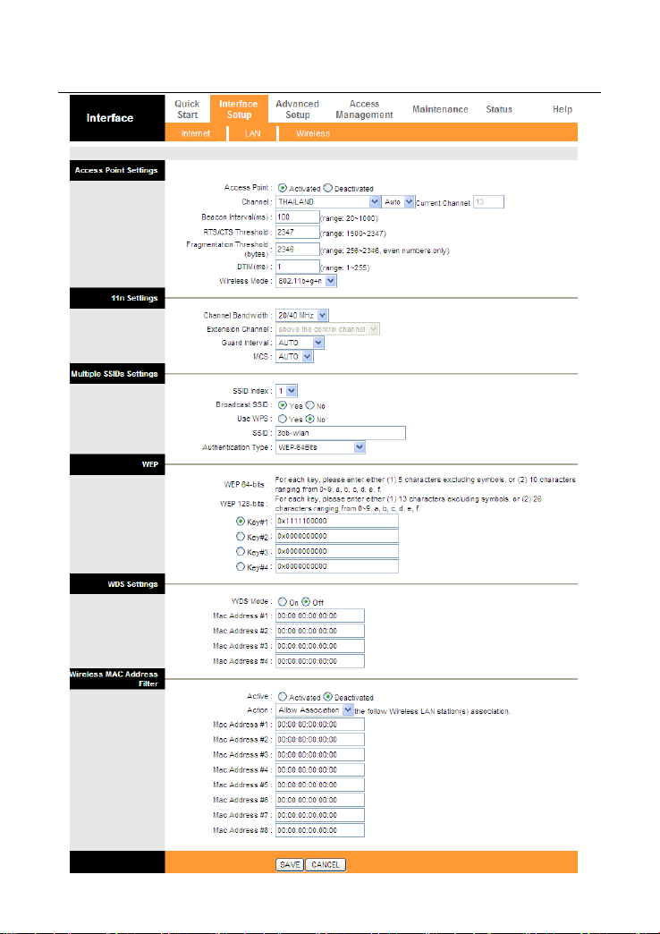
Choose Interface Setup > Wireless. The page as shown in the following figure
appears.
11
Page 12
NT3BB-1PWN Error! Use the Home tab to apply 标题 to the text that
you want to appear here.
12
Page 13

NT3BB-1PWN Error! Use the Home tab to apply 标题 to the text that
Field
Description
Access Point
You may choose Activated or Deactivated.
Channel
Countries apply their own regulations to both the
allowable channels, allowed users and maximum
power levels within these frequency ranges. The
default is 13.
Beacon Interval
Beacon Interval range is from 20 to 1000.
RTS/CTS Threshold
RTS/CTS Threshold range is from 1500 to 2347.
Fragmentation
Threshold
Fragmentation Threshold range are only even
numbers between 256 and 2346.
DTIM
DTIM range is from 1 to 255. A delivery traffic
indication message is a kind of traffic indication
message (TIM) which informs the clients of the
presence of buffered multicast/broadcast data on
the access point.
Wireless Mode
Comply with the IEEE 802.11b/g and IEEE802.11n
standards. You can select 802.11b, 802.11g,
802.11b+g, 802.11n, 802.11g+n or 802.11b+g+n.
Channel Bandwidth
Supporting 20MHz/40MHz Dual Channel.
Extension Channel
You can set below the control channel or above
the control channel.
Guard Interval
You can set 800 nsec or AUTO.
MCS
You can set an MCS index between 0 and 7, or
select AUTO.
SSID index
Support only a root SSID to be modified.
SSID
The service set identification (SSID) is a unique
name to identify the router in the wireless LAN.
You may modify the SSID.
Broadcast SSID
Select whether the router broadcasts SSID or not.
You can select Yes or No.
Select Yes, and the wireless client searches
the router through broadcasting SSID.
Select No to hide SSID, and the wireless
you want to appear here.
The following table describes the parameters of this page:
13
Page 14

NT3BB-1PWN Error! Use the Home tab to apply 标题 to the text that
Field
Description
client can not search the SSID.
Use WPS
WPS technology allows new customers without a
previously-established account to securely
connect to your network at the Wi-Fi hotspot,
create and pay for an account, and access the
Internet.
SSID
The default is 3bb-wlan.
Authentication Type
You can set a type from Disabled, WEP-64Bits,
WEP-128Bits, WPA-PSK, WPA2-PSK,
WPA-PSK/ WPA2-PSK.
Key#1~4
When WEP-64Bits is selected, enter 5 characters
or 10 hexadecimal digits ("0-9", "A-F") preceded
by “0x” for each Key.
When WEP -128Bits is selected, enter 13
characters or 26 hexadecimal digits("0-9", "A-F")
preceded by “0x” for each Key.
WDS state
Choose to enable or disable WDS (Wireless
Distribution System).
Mac Address #1~4
Enter the MAC address of the opposite end.
Active
Activate or deactivate Wireless MAC Address
Filter.
Action
You can set Allow or Deny to make Wireless LAN
station(s) association. This function can be used
to allow or deny access to certain wireless clients
based on their MAC Address.
Mac Address #1~8
You can set eight Mac Addresses at most.
you want to appear here.
14
 Loading...