

Page 1

www.2n.cz
2N Indoor Touch 2.0
®
User guide
Version: 4.0.x
Page 2

The 2N TELEKOMUNIKACE a.s. is a Czech manufacturer and supplier of
telecommunications equipment.
The product family developed by 2N TELEKOMUNIKACE a.s. includes GSM gateways,
private branch exchanges (PBX), and door and lift communicators. 2N
TELEKOMUNIKACE a.s. has been ranked among the Czech top companies for years
and represented a symbol of stability and prosperity on the telecommunications
market for almost two decades. At present, we export our products into over 120
countries worldwide and have exclusive distributors on all continents.
2N is a registered trademark of 2N TELEKOMUNIKACE a.s. Any product and/or other
®
names mentioned herein are registered trademarks and/or trademarks or brands
protected by law.
2N TELEKOMUNIKACE a.s. administers the FAQ database to help you quickly find
information and to answer your questions about 2N products and services. On www.
faq.2n.cz you can find information regarding products adjustment and instructions for
optimum use and procedures „What to do if...".
2N TELEKOMUNIKACE a.s. hereby declares that the 2N product complies with all
basic requirements and other relevant provisions of the 1999/5/EC directive. For the
full wording of the Declaration of Conformity see the CD-ROM (if enclosed) or our
website at www.2n.cz.
The 2N TELEKOMUNIKACE a.s. is the holder of the ISO 9001:2009 certificate. All
development, production and distribution processes of the company are managed by
this standard and guarantee a high quality, technical level and professional aspect of
all our products.
Page 3

Content:
1. Product Overview
1.1 Product Description
1.2 Differences between Models
1.3 Terms and Symbols
1.4 Safety Precautions
2. Description and Installation
2.1 Before You Start
2.2 Brief Installation Guide
2.3 Installation Conditions
2.4 Status LED
2.5 First Startup
2N TELEKOMUNIKACE a.s., www.2n.cz 3/135
Page 4

3. 2N® Indoor Touch 2.0 Configuration
3.1 Factory Reset
3.2 Home Screen
3.3 Device Configuration
3.3.1 User Settings
3.3.1.1 Device
3.3.1.2 Personal
3.3.1.2.1 Security
3.3.1.2.2 Language and Input Methods
3.3.1.3 System
3.3.1.3.1 Date & Time
3.3.1.3.2 Backup & Reset
3.3.2 Administrator Settings
3.3.2.1 Device
3.3.2.2 Wireless & Networks
3.3.2.3 Security
3.3.2.4 Backup & Reset
3.3.3 Intercoms
3.3.3.1 General Settings
3.3.3.2 Call Settings
3.3.3.3 My2N/SIP Configuration
3.3.3.4 Video
3.3.3.5 Recorder
3.3.3.6 Input and Output
3.4 Device Upgrade
2N TELEKOMUNIKACE a.s., www.2n.cz 4/135
Page 5

4. Intercoms Applications Configuration
4.1 Application Description
4.2 Application Environment and Configuration
4.2.1 Device
4.2.2 Call Log
4.2.3 Dial Pad
4.2.4 Settings
4.3 Notifications in 2N® Indoor Touch Environment
4.4 Application Use
4.4.1 LAN Calls
4.4.2 SIP Proxy Server Calls
4.4.3 2N® Mobile Video Calls
4.5 Supplementary Information
4.5.1 Troubleshooting
5. Web Interface Configuration
5.1 Login
5.2 System Info
5.2.1 Status
5.3 Device
5.3.1 Network
5.3.2 Home Screen
5.3.3 Local Settings
5.3.4 Display
5.3.5 Audio
5.3.6 System Administration
5.4 Application
5.4.1 Intercoms
5.4.2 Settings
5.5 Limitations
6. Technical Parameters
7. Supplementary Information
7.1 Troubleshooting
7.2 Directives, Laws and Regulations - General Instructions and Cautions
2N TELEKOMUNIKACE a.s., www.2n.cz 5/135
Page 6

1. Product Overview
In this section, we introduce the product, outline its application 2N Indoor Touch 2.0
®
options and highlight the advantages following from its use. The section also includes
safety precautions.
Here is what you can find in this section:
1.1 Product Description
1.2 Differences between Models
1.3 Terms and Symbols
1.4 Safety Precautions
2N TELEKOMUNIKACE a.s., www.2n.cz 6/135
Page 7

1.1 Product Description
Based on the Android OS, helps load third party applications to 2N Indoor Touch 2.0
®
a device (if enabled so in the device configuration), thus improving its flexibility. It
contains a 7" colour LCD display with a capacitive touch layer, loudspeaker,
microphone and Ethernet and WiFi interfaces (depending on the Part No.) for LAN
connection. Analogue inputs and outputs are also part of the equipment.
2N Indoor Touch 2.0® has a factory pre-installed application – , which 2N IP Mobile
®
helps establish video calls with any other video call supporting devices (SIP + H.263
/4). Primarily, the application is intended for the family.2N IP intercom
2N Indoor Touch 2.0® contains a specific user interface for an increased user comfort
and safety.
2N Indoor Touch 2.0® basic features:
7" LCD colour display with capacitive touch layer
Wall mounting option
LAN interface with PoE supply option
802.11bgn WiFi interface (depending on the Part No.)
Status RGB LED at front
Binary inputs and outputs for control of other devices
Android operating system with pre-installed basic applications and own user
interface
Pre-installed application 2N IP Mobile
®
2N TELEKOMUNIKACE a.s., www.2n.cz 7/135
Page 8

1.2 Differences between Models
This manual is valid for all the types. Therefore, please note that 2N Indoor Touch 2.0
®
several features described in this document are only available in selected models or
need to be activated with a licence key. If a feature is not available in all the models, a
note is added to the respective subsection.
2N ® Indoor Touch Types 2.0
Part Nos.:
91378375
91378376
– black2N Indoor Touch 2.0
®
WiFi version (lower Part No.)
Part Nos.:
91378375WH
91378376WH
– white2N Indoor Touch 2.0
®
WiFi version (lower Part No.)
2N TELEKOMUNIKACE a.s., www.2n.cz 8/135
Page 9

Accessories
Part No.:
91378382, 01425-001
2N Indoor Touch® desk stand black
Part No.:
91378382W, 01426-001
2N Indoor Touch® desk stand white
Part Nos.:
91378381E
91378381GB
91378381US
Stabilised 12 V / 0,75 A source to be used where PoE
supply is unavailable.
The part numbers differ in their electric socket
markings (E/GB/US).
The exclusive type of power adapter to SYS1561-0912
be used with all 2N Indoor Touch 2.0 devices.
®
2N TELEKOMUNIKACE a.s., www.2n.cz 9/135
Page 10

Licence
Part No. Description
91378395 – the licence unlocks the HTTP API functionsHTTP API
2N TELEKOMUNIKACE a.s., www.2n.cz 10/135
Page 11

1.3 Terms and Symbols
The following symbols and pictograms are used in the manual:
Safety
Always abide by this information to prevent persons from injury.
Warning
Always abide by this information to prevent damage to the device.
Caution
Important information for system functionality.
Tip
Useful information for quick and efficient functionality.
Note
Routines or advice for efficient use of the device.
2N TELEKOMUNIKACE a.s., www.2n.cz 11/135
Page 12

1.4 Safety Precautions
The manufacturer reserves the right to modify the product in order to improve its
qualities. The manufacturer continuously responds to the clients' requirements by
improving the software. Refer to the company websites for the latest www.2n.cz 2N
®
firmware and User Manual.Indoor Touch 2.0
It is prohibited to use any transmitters, including with an 2N Indoor Touch 2.0®
internal WiFi adapter, in areas where explosives are used, such as quarries.
WiFi adapters may affect sensitive life-saving devices in medical centres.
Therefore, it is prohibited to use device with an internal WiFi adapter in such
facilities.
In general, any RF energy radiation prohibition regarding WiFi antenna equipped
devices applies to device with an internal WiFi adapter.
Where necessary, a device unit can be installed at a safe distance from the
prohibited area and an Ethernet cable can only be carried to the required site.
Although the device is not intended for cars or aeroplanes, all prohibitions and
regulations relating to adapter equipped devices apply to device too.
2N TELEKOMUNIKACE a.s., www.2n.cz 12/135
Page 13

2. Description and Installation
This section describes the installation and correct connection.2N Indoor Touch 2.0
®
Here is what you can find in this section:
2.1 Before You Start
2.2 Brief Installation Guide
2.3 Installation Conditions
2.4 Status LED
2.5 First Startup
The device is designed solely for wall mounting. Install the device with the aid of a
holder, which is included in the product and Installation Manual delivery.
Prepare the proper wall fittings (screws and wall plugs suitable for the given wall type
and structure). Respect the local standards for installation of electronic devices onto
flammable materials while mounting!
Use a cross-point screwdriver for tightening the fitting screws on the device sides to
place properly.2N Indoor Touch 2.0
®
2N TELEKOMUNIKACE a.s., www.2n.cz 13/135
Page 14
2.1 Before You Start
Product Completeness Check
Please check the delivery before starting installation:2N Indoor Touch 2.0
®
1
2N Indoor Touch 2.0
®
1 Quick Start manual
1 Wall holder (screwed to device)
1 Installation fittings (2 screws, 2 plugs for flush mounting)
1 Microfiber screen cleaning cloth
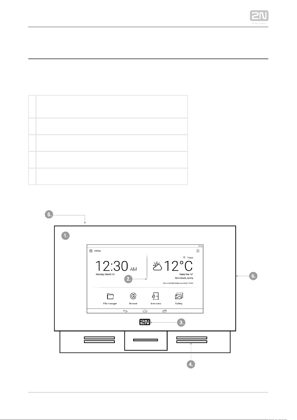
Front Layout
2N TELEKOMUNIKACE a.s., www.2n.cz 14/135
Page 15

1.
2.
3.
4.
5.
6.
Glass frame
LCD display with capacitive touch layer
Status RGB LED
Loudspeaker
Microphone
Micro SD card slot
Backside Connectors
2N TELEKOMUNIKACE a.s., www.2n.cz 15/135
Page 16

1.
2.
3.
4.
5.
6.
RJ-45 LAN 10/100BaseT connector
12 V / 0,75 A DC supply terminal board (only if PoE is not used)
Restart/Factory reset button
Binary input/output terminal board (for application control)
Micro SD card slot
Logic inputs and outputs
Tip
External doorbell button or Relay connection guides are available at faq.
.2n.cz
Warning
Do not remove the backside rubber sealing as it improves the accoustic
properties of the product during wall mounting.
2N TELEKOMUNIKACE a.s., www.2n.cz 16/135
Page 17

1.
2.
a.
b.
c.
3.
a.
b.
4.
2.2 Brief Installation Guide
Install the device holder onto a vertical wall. The recommended installation
height is 120 cm above the floor. The product package includes screws and plugs
for mounting into classic bricks. Use appropriate installation fittings for a
different type of wall material!
Feed the device via an Ethernet PoE adapter (or PoE supporting Ethernet switch
/router) or a 12 V / 0,75 A DC power adapter.
With PoE supply, just snap RJ-45 into the appropriate connector.
With 12 V DC 0,75 A supply, screw the power adapter plus and minus
cables into the appropriate terminal board on the device.
Simultaneous PoE + 12 V / 0,75 A DC supply is not recommended!
Put the device on the holder as follows:
Place the device carefully from top to bottom with its bottom part slightly
away (up to 5 cm) from the wall.
When the device fits to the main holder supports, push the device bottom
part onto the wall.
Tighten the safety screws on both the device sides.
2N TELEKOMUNIKACE a.s., www.2n.cz 17/135
Page 18

1.
2.
3.
4.
2.3 Installation Conditions
Make sure that the following installation conditions are met:2N Indoor Touch 2.0
®
There must be enough space for device installation.
Device is designed for vertical wall mounting (perpendicular to the floor) in the
height of up to 120 cm above the floor. If necessary, operate device in a position
other than as aforementioned for a short time only, for quick testing purposes in
a servicing centre, for example.
Exceeding the allowed operating temperature may not affect the device
immediately but leads to premature ageing and lower reliability. Refer to
for the acceptable range of operating temperatures and 6. Technical Parameters
relative humidity values.
Device is not designed for environments with increased vibrations such as
means of transport, machine rooms and so on.
Device is not intended for dusty environments and places with unstable humidity
and abrupt temperature changes.
Device may not be exposed to aggressive gas, acid vapours, solvents, etc.
Device is not intended for direct connection into the Ethernet/Internet.
Device must be connected to the Ethernet/Internet via a separating active
network element (switch/router).
Device is designed for indoor use. It may not be exposed to rain, flowing water,
condensing moisture, fog, etc.
Device cannot be operated on places exposed to direct sunshine and near heat
sources.
Keep some free space above and below device to allow air to flow and conduct
heat away.
No strong electromagnetic radiance is allowed on the installation site.
The VoIP connection must be configured properly according to the SIP and
other VoIP recommendations.
It is recommended that the power adapter be connected to the mains via a UPS
and reliable overvoltage protection.
Wall Mounting
is designed for wall mounting. Follow the steps below:2N Indoor Touch 2.0
®
Unscrew the holder-fitting screws on the device sides.
Turn the metal holder slightly aside in the upper part of the device.
Move the holder downwards.
Fit the loose holder to the wall on the installation site.
2N TELEKOMUNIKACE a.s., www.2n.cz 18/135
Page 19

5.
1.
2.
Put the device on the holder and tighten the safety screws.
Follow the installation instructions printed on the device package.
Power Supply Connection
You can feed as follows:2N Indoor Touch 2.0
®
Use 12 V / 0,75 A DC power adapter (order no. 91378381E/91378381GB
/91378381US)connected to the terminal board (see the figure).
Use an Ethernet cable connected to a PoE supply or PoE supporting Ethernet
switch/router.
A successful operation is indicated by a status RGB LED or LCD display.
PoE Supply Connection
Use a standard straight RJ-45 terminated cable to connect device to the Ethernet. The
device supports the 10BaseT and 100BaseT protocols. The Ethernet connection state
is indi cated by the L EDs placed on the RJ-45 connec tor.
Refer to for the factory settings of the device Ethernet 3.3 Device Configuration
interface.
Caution
Factory reset results in a change of the Ethernet interface configuration!
A defective Ethernet cable may lead to a high packet loss in the
Ethernet and subsequent instability and poor video call quality!
Warning
Connection of a defective or improper power adapter may lead to a
temporary or permanent failure of the unit!2N Indoor Touch 2.0
®
2N TELEKOMUNIKACE a.s., www.2n.cz 19/135
Page 20

Ethernet cable connector Ethernet port
Licence Limitations
2N Indoor Touch 2.0® can contain time-limited software licences. Refer to 3.3 Device
for details.Configuration
Firmware Upgrade
We recommend you to upgrade the device firmware during installation. Refer to www.
for the latest FW version. Refer to for the firmware upgrade 2n.cz 3.4. Device Upgrade
procedure.
2N TELEKOMUNIKACE a.s., www.2n.cz 20/135
Page 21

2.4 Status LED
Status LED indicates the device states when the LCD display is switched off or the
device is in the service mode. See the table below for the LED colours and states:
Device Startup:
Colour State
Blue is on Device initialisation
Red is on First boot phase
Green is on Operating system start
Yelow is on Factory setting initialisation
Blue is flashing Factory reset
Purple is flashing System upgrade process
No light Device state is displayed
Standard Operation:
Colour State
No light Device state is displayed
Blue is on Stand-by mode (display off)
Other
states
Notification of other states of applications running in the system ( , e.2N IP Mobile
®
g.).
2N TELEKOMUNIKACE a.s., www.2n.cz 21/135
Page 22

2.5 First Startup
When you start the device for the first time, the initial initialisation (longer start) is
performed and indicated by the following LED notification sequence: Red Blue Green
Boot animation on the screen Introductory system screen.
The introductory screen provides essential information for User Manual saving
/reading. Select "Don't show welcome screen and run 2N IP Mobile® at next start
instead" to deactivate this screen for future system startups.
Caution
If you do not select the "Don't show welcome screen and run 2N IP
®
at next start instead" option on the welcome screen before Mobile
quitting and then enable the launch after the system 2N IP Mobile
®
startup in the Launcher configuration, the application will not be started
for technical reasons. Therefore, be sure to disable the welcome screen
start to make run automatically after the system startup.2N IP Mobile®
The table below shows the factory values of relevant device parameters:
Parameter Value
IP address will be assigned by the DHCP server
IP mask will be assigned by the DHCP server
IP gateway will be assigned by the DHCP server
Access password to configuration 2n
Administrator password 2n
Time/weather location Prague, CZ
Stand-by switching time 1 minute
SW licence
Basic unlimited licence
2N TELEKOMUNIKACE a.s., www.2n.cz 22/135
Page 23

Parameter Value
(or according to the Part No.)
Caution
Change the access password while configuring the device for the first
time to avoid unauthorised access to configuration!
System Licence
2N Indoor Touch 2.0® has a factory licence key, which can be time-limited (depending
on the Part No.). The licence expiry may cause a partial limitation of the device
functionality! Refer to for the current licence state and licence 3.3 Device Settings
adding procedure if necessary.
2N TELEKOMUNIKACE a.s., www.2n.cz 23/135
Page 24

3. 2N® Indoor Touch 2.0 Configuration
This section describes the configuration.2N Indoor Touch 2.0
®
Here is what you can find in this section:
3.1 Factory Reset
3.2 Home Screen
3.3 Device Configuration
3.4 Device Upgrade
2N TELEKOMUNIKACE a.s., www.2n.cz 24/135
Page 25

1.
2.
a.
b.
c.
3.1 Factory Reset
Follow the steps below to reset the factory values:2N Indoor Touch 2.0
®
Press the Factory Data Reset button in Settings / Administrator mode – ON /
Backup & reset.
Press and hold the Reset button on the device backside:
Remove the device from the installation holder.
Press and hold the Reset button until the notification RGB LED lights up
(yellow, approx. 10 seconds).
Release the Reset button and follow the instructions displayed.
Caution
You can reset the factory values only if the administrator mode is on.
Factory reset results in a complete deletion of all user data.
2N TELEKOMUNIKACE a.s., www.2n.cz 25/135
Page 26

3.2 Home Screen
The Home Screen is divided into three subsections: Current time and date, Weather
widget and five configurable application positions. The Setting and Information
buttons are also available here.
Factory settings:
Time/Date tiles
Weather tile
File Manager – standard file system application
Browser – Internet browser application
Intercoms – application responsible for communication of the 2N IP intercoms
with other answering units
Gallery – photo/image processing application
2N TELEKOMUNIKACE a.s., www.2n.cz 26/135
Page 27

The lower graphic bar includes five graphic controls:
Back icon (triangle) – return one level higher or one step back (depending on
the application type).
Home icon (circle) – return to the introductory screen.
Square icon – switch the currently launched applications.
Speaker icons – increase/decrease the system loudspeaker volume.
2N TELEKOMUNIKACE a.s., www.2n.cz 27/135
Page 28

3.3 Device Configuration
Click the button on the introductory page to access the configuration section. Settings
Complete the correct access password.
Caution
The factory access password is "2n“. If you lose the access data, you will
have to factory reset the device! Change the password in the Settings /
Personal / Language & input.
Administrator mode – configure advanced functions.
The device configuration consists of five sections: Device, Wireless & Networks, 2N® IP
Mobile, Personal, System; each section is divided into subsections, see below.
3.3.1 User Settings
3.3.2 Administrator Settings
3.3.3 Intercoms
2N TELEKOMUNIKACE a.s., www.2n.cz 28/135
Page 29

3.3.1 User Settings
This subsection describes the settings that can be accessed without the administrator
password. The subsection contains the following parts:
3.3.1.1 Device
3.3.1.2 Personal
3.3.1.3 System
2N TELEKOMUNIKACE a.s., www.2n.cz 29/135
Page 30

3.3.1.1 Device
This section helps you set the first menu level and quick navigation parameters (click
any subsection) into selected device configuration sections.
Do Not Disturb Mode
– disable any notification while DND is active. While Do Not Disturb (DND)
activating DND you can set any interval in the range between 15 minutes and 24
hours, or permanently.
– disable any notification while DND is active. Do Not Disturb (DND) Night mode
Set this mode for each weekday with repetition and specify the start and end
time.
– set the beginning of the DND Night mode time validity.Start time
– set the end of the DND Night mode time validity.End time
2N TELEKOMUNIKACE a.s., www.2n.cz 30/135
Page 31

– set the days on which the DND Night mode is to be applied Repeat
repeatedly.
Home Screen
– click to move the user to the section for setting the time, time format and Time
time zone.
– activate the use of date and time from the Automatic date & time
network.
– set the date and time manually if Automatic date Set date and time
and time is disabled.
– set the time zone for the installation site to include the Select time zone
time shift and summer/winter time transition.
– display the 24-hour format. If disabled, the 12-hour Use 24-hour format
format is displayed including the a.m./p.m. information.
– select one of the three available date formats.Choose date format
click to move the user to the section for setting the current weather – Weather
forecast. Use the introductory weather tile to deactivate the function. Deactivate
the weather tile if necessary.
– set the geographical position of the installation site manually.Position
– set 60 or 120 minutes for weather info refreshment.Refresh frequency
– set metric (°C) or imperial (°F) units.Units
– display the weather info source.Source
2N TELEKOMUNIKACE a.s., www.2n.cz 31/135
Page 32

Tip
The weather forecast location includes the town and abbreviated
country name. If typed incorrectly, the weather forecast will not be
displayed. make sure that the Internet is connected while setting the
location. refer to http://openweathermap.org/ for location codes .
Pre-Installed Applications
– a file management application, which can be replaced with any File manager
other application.
– a www navigation tool, which can be replaced with any other Browser
application.
– provides communication with the 2N IP intercoms and other Intercoms
answering units and can be replaced with any other application.
– an image/photo processing application, which can be replaced with Gallery
any other application
– add an application from a list and edit its name/icon if Add Application
necessary.
Caution
The application installations depend on the product licensing. Make sure
that the key is active to install an application. Check Settings / APP
Device / Licence after activating the administrator mode for the current
licence state.
2N TELEKOMUNIKACE a.s., www.2n.cz 32/135
Page 33

Sound & Notification
– set the media volume.Media volume
– set the alarm clock volume.Alarm volume
– set the default notification ringtone volume.Notification volume
– set the default notification ringtone.Default notification ringtone
– enable/disable sound signalling.Other sounds
– enable/disable the screen lock sound.Screen locking sound
– enable/disable the display touch sound.Touch sounds
2N TELEKOMUNIKACE a.s., www.2n.cz 33/135
Page 34

Display
– set the backlight brightness values.Brightness level
– set the maximum user idle timeout after which the sleep mode is Sleep
automatically switched on. Select a value between 15 seconds and 30 minutes or
never.
– set the font size: Small / Normal / Large / Very large.Font size
2N TELEKOMUNIKACE a.s., www.2n.cz 34/135
Page 35

Storage & USB
– display the internal storage state for downloaded files and Internal storage
photos. Click to display the storage details.
– display the external storage state for downloaded files and Portable storage
photos.
2N TELEKOMUNIKACE a.s., www.2n.cz 35/135
Page 36

Advanced
The Advanced subsection is only available when the administrator mode is active.
– display the list of available applications. Application to be launched on startup
Select the application to be launched upon startup.
– set the URL address to be opened upon startup.URL to be opened on startup
– set return to the application when the call Return to application after call end
is terminated.
– turn the blue LED on when the display is Turn on blue LED when display is off
off.
2N TELEKOMUNIKACE a.s., www.2n.cz 36/135
Page 37

Licence
The Licence subsection is only available when the administrator mode is active.
– display the licence key used.Licence key
– display the list of available functions depending on the Available functions
licence type purchased.
– display the licence type (limited, unlimited).Status
– display the licence remaining hours.Remaining hours
– change the licence key.Change licence key
Caution
The original licence key will be overwritten by the new one! Be sure to
insert a valid licence key obtained from your supplier!
2N TELEKOMUNIKACE a.s., www.2n.cz 37/135
Page 38

Warning
The licence unlocks for loading user APP 2N® Indoor Touch 2.0
applications from a microSD card (SDHC), up to 16 GB. If, however, any
user applications are installed, does not 2N TELEKOMUNIKACE a.s.
guarantee a proper function and stability of such user applications and
/or a correct function of the applications pre-installed in 2N® Indoor
. Should troubles occur, remove the user applications or reset Touch 2.0
the factory values to get rid of the user applications and settings.device
Device Info
– display basic information on the device (serial number, hardware Device
version, firmware version...).
– display the official name of the device. System
– display the device date and time.Date and time
– display the RAM state.RAM info
– display the list of open-source licences used in the device.Legal information
2N TELEKOMUNIKACE a.s., www.2n.cz 38/135
Page 39

3.3.1.2 Personal
The Personal section helps you set the device security and language parameters.
3.3.1.2.1 Security
3.3.1.2.2 Language and Input Methods
2N TELEKOMUNIKACE a.s., www.2n.cz 39/135
Page 40

3.3.1.2.1 Security
Set the device security parameters.
PASSWORD
– set the setting access password.Settings password
– set the administrator access Administrator and web access password
password.
SCREEN SECURITY
– select the screen lock type: PIN, Character or None.Screen lock
UNKNOWN SOURCES
– Allow installation of apps from unknown sources allow installation of
applications from unknown sources.
2N TELEKOMUNIKACE a.s., www.2n.cz 40/135
Page 41

3.3.1.2.2 Language and Input Methods
Set the language parameters and text input methods.
– set the system language.Language
– enable/disable the spell checker for the defined language.Spell checker
– click Add (+) to add a word to your personal dictionary.Personal dictionary
KEYPAD & INPUT METHODS
– set the keyboard type. Current Keyboard
– set the keyboard parameters. Android Keyboard (AOSP)
Tip
Disable the display tap sound signalling in the Settings / Sound device
menu.
2N TELEKOMUNIKACE a.s., www.2n.cz 41/135
Page 42

3.3.1.3 System
This section helps you set the system parameters.
3.3.1.3.1 Date & Time
3.3.1.3.2 Backup & Reset
2N TELEKOMUNIKACE a.s., www.2n.cz 42/135
Page 43

3.3.1.3.1 Date & Time
This section helps you set the device date and time parameters. Set the time, time
format and time zone.
– activate the use of date and time from the network.Automatic date & time
– set the date manually if Automatic date & time date is disabled.Set date
– set the time manually if Automatic date & time time is disabled.Set time
– set the time zone for the installation site to include the time Select time zone
shift and summer/winter time transition.
– display the 24-hour format. If disabled, the 12-hour format Use 24-hour format
is displayed including the a.m./p.m. information.
2N TELEKOMUNIKACE a.s., www.2n.cz 43/135
Page 44

3.3.1.3.2 Backup & Reset
This section helps you set the device data backup and reset parameters.
– restart the device.Restart
Factory data reset – delete all data from the internal storage including: system
and application settings and data, downloaded applications, music, photographs
and other user data. The factory data reset is only available in the administrator
mode.
2N TELEKOMUNIKACE a.s., www.2n.cz 44/135
Page 45

3.3.2 Administrator Settings
This subsection describes the settings that can be accessed after the administrator
password in entered. The subsection has the following parts:
3.3.2.1 Device
3.3.2.2 Wireless & Networks
3.3.2.3 Security
3.3.2.4 Backup & Reset
2N TELEKOMUNIKACE a.s., www.2n.cz 45/135
Page 46

3.3.2.1 Device
Advanced
The Advanced subsection is available in the administrator mode only.
– display the list of available applications. Application to be launched on startup
Select an application to be launched on startup.
– set the URL to be launched on startup.URL to be launched on startup
– return to the application after the call is Return to application after call end
ended.
– turn on the blue LED when the display is Turn on blue LED when display is off
off. Move to Screen.
– connect a service device to the device.Enable service mode
– set the home page to the default Android Launcher.Set Android Launcher
2N TELEKOMUNIKACE a.s., www.2n.cz 46/135
Page 47

Licence
The Licence subsection is available in the administrator mode only.
– display the licence key used.Licence key
– display the list of available functions depending on the Available function
licence type purchased.
– display the license status (limited, unlimited).Status
– display the hours remaining before the licence expires.Remaining hours
– change the licenced key.Change licence key
Caution
The original licence key will be overwritten with a new one! Enter only
the valid licence key obtained from your supplier!
2N TELEKOMUNIKACE a.s., www.2n.cz 47/135
Page 48

Warning
The licence unlocks for uploading custom APP 2N® Indoor Touch 2.0
applications from a max 16 GB microSD card (SDHC). 2N
cannot guarantee functionality and stability of TELEKOMUNIKACE a.s.
custom applications or proper function of applications pre-installed in 2N
once custom applications are installed. In case of
®
Indoor Touch 2.0
troubles, remove the custom applications or reset the factory values to
get rid of the custom applications and settings.
2N TELEKOMUNIKACE a.s., www.2n.cz 48/135
Page 49

3.3.2.2 Wireless & Networks
This section helps you set the network connection parameters. Connection can be set
via the Ethernet or Wi-Fi (depending on the Part No., refer to Subs. 1.2 Differences
).between Models and Associated Products
– disable/enable the Wi-Fi connection.Wi-Fi
– disable/enable the Ethernet connection.Ethernet
Note
Ethernet connection cannot be used together with Wi-Fi.
By disabling the Ethernet connection you do not switch off the device
when PoE is used.
The Wi-Fi section displays the list of available Wi-Fi networks.
2N TELEKOMUNIKACE a.s., www.2n.cz 49/135
Page 50

– enable/disable the adapter.Enabled
– enable/disable the DHCP client.Use DHCP
– display the IP address.IP Address
– display the MAC address.MAC Address
– configure the Ethernet manually.Configuration
2N TELEKOMUNIKACE a.s., www.2n.cz 50/135
Page 51

3.3.2.3 Security
This subsection describes the administrator security settings.
PASSWORD
– set the access password type for the Settings:Setting password
– no access password is required.None
– set a password containing at least four letters.Password
– set a code containing at least four digits.PIN
– set the administrator mode and web Administrator and web access password
interface access password.
– set separate passwords for the Use separate web access password
administrator mode and device web interface.
– set the administrator access password.Administrator password
– set the web interface access password.Web access password
2N TELEKOMUNIKACE a.s., www.2n.cz 51/135
Page 52

SCREEN LOCK
– set the screen lock password type The screen lock is activated Screen lock .
after the sleep mode timeout set in the Device / Screen / Sleep mode menu
elapses.
– no screen lock.None
– set the screen lock deactivation gesture.Pattern
– set the numeric PIN for screen lock deactivation.PIN
UNKNOWN SOURCES
– allow installation of Allow application installation from unknown sources
applications from unknown sources.
2N TELEKOMUNIKACE a.s., www.2n.cz 52/135
Page 53

3.3.2.4 Backup & Reset
This subsection describes the administrator options.
– set the language for the texts to be displayed.Language
– enable/disable the spell checker function.Spell checker
– add terms of your own including optional abbreviations to Personal directory
the dictionary.
KEYBOARD & INPUT METHODS
– set the keyboard type.Current Keyboard
– set the additional parameters of the Android Android Keyboard (AOSP)
keyboard.
2N TELEKOMUNIKACE a.s., www.2n.cz 53/135
Page 54

3.3.3 Intercoms
This subsection describes how to configure the pre-installed application.Intercoms
3.3.3.1 General Settings
3.3.3.2 Call Settings
3.3.3.3 My2N/SIP Configuration
3.3.3.4 Video
3.3.3.5 Recorder
3.3.3.6 Input and Output
2N TELEKOMUNIKACE a.s., www.2n.cz 54/135
Page 55

3.3.3.1 General Settings
This section helps you set the Intercoms general parameters.
GENERAL
– set the device name for identification to other Device Name 2N IP Mobile
®
LAN devices.
– set the application setting password via link click from the Password
application.
– set the authentication password.Access Key 2N IP intercom
Tip
Refer to faq.2n.cz for the instructions for use.Access key
– enable/disable to acquire an image from the Autosnapshot Autosnapshot
video preview. The image replaces the circle avatar at the added devices in the
Device and Call Log menus.
– select the communication type for one-directional half-duplex Push to Talk
communication: ON/OFF (ON by default).
– enable/disable application logging to the system log.Logging
– ON/OFF (ON by default). With ON, Multicast Discovery 2N Indoor Touch 2.0
®
sends the info packets to the network in the multicast mode. With OFF, 2N
®
sends the info packets in unicast to the IP address of the 2N IP Indoor Touch 2.0
2N TELEKOMUNIKACE a.s., www.2n.cz 55/135
Page 56

intercom to be monitored and periodically to all the 2N IP intercoms included in
the LAN device list. The info packets are sent in unicast to the 2N IP intercoms
only, not to other LAN devices.2N Indoor Touch 2.0
®
LOCALIZATION
– use custom modified texts, which are not part of the Custom language
application package. Use JSON strings to set the language.
The custom translations are optionally available in the translationMap.json file in an
external storage (physical or emulated SD card), which matches the following path:
./sdcard/hipmo-localization/translationMap.json
The hipmo-localization folder is automatically created on the first available SD card
upon the application start. If there are multiple SD cards in the device and you do not
know which to use, check the SD cards for the folder upon startup.
Note
Make sure that the file name is " " without any translationMap.json
additional (language) extensions or insertions. For example,
translationMap-cs.json is wrong.
Text File Structure
The custom translation JSON includes the data root, which is an array of translation
elements:
{"data":[
translation,
translation,
...
translation
]}
Each translation element has the following structure:
{"key":{"hint":"hint_string","value":"translated_string"}}
where
2N TELEKOMUNIKACE a.s., www.2n.cz 56/135
Page 57

– text string key (replaces name in strings.xml).key
– text meaning.hint_string
– custom translation.translated_string
Example:
{"title_call_declined":{"hint":"Call declined","value":"Call declined"}}
You are recommended to edit translated_string only and not modify hint_string unless
necessary.
Warning
We do not advise you to edit the text string to avoid unexpected KEY
actions of the application.
The application searches the asset for a file that matches the current Locale setting in
the device. If there is one, the application adds the keys included in the file to the map.
Should there be a match, old values are replaced with new ones.
The application checks the Custom Localization switch status. If the function is on and
the corresponding custom translation file is available in the device, the application
adds the keys to the map as mentioned above.
Caution
Untranslated strings are displayed in English.
2N TELEKOMUNIKACE a.s., www.2n.cz 57/135
Page 58

3.3.3.2 Call Settings
This section helps you set the call parameters.
CALL
– select the default ringtone.Call ringtone 2N IP Mobile
®
– load an audio file to be used as the ringtone. The Custom ringtone file
supported format is .wav, 15 MB, shortened to 15 s, PCM8/PCM16.
– set the automatic incoming call answering.Automatic call pickup
– set the automatic call pickup timeout to 0–Automatic call pickup delay
20 seconds.
2N TELEKOMUNIKACE a.s., www.2n.cz 58/135
Page 59

3.3.3.3 My2N/SIP Configuration
This section helps you set the My2N and SIP Proxy parameters.
MY2N
– enable/disable .My2N Mobile Video 2N IP Mobile
®
– set the device ID assigned by .Device ID 2N IP Mobile
®
– set the device password for connection, generated Password 2N IP Mobile
®
automatically.
2N TELEKOMUNIKACE a.s., www.2n.cz 59/135
Page 60

SIP PROXY
– enable/disable the SIP Proxy.SIP Proxy
– set the account name to be displayed in the application.Display name
– set the SIP Proxy server username.Username
– set the SIP Proxy server user password.Password
– set the SIP Proxy server IP address/domain name.Server
– set the SIP Proxy server port (default is 5060).Port
– select the transport protocol: TCP or UDP.Transport
2N TELEKOMUNIKACE a.s., www.2n.cz 60/135
Page 61

SIP REGISTRAR
Registrar – set the SIP Proxy IP address or domain name.
Address – set the SIP Registrar IP address or domain name.
Port – set the SIP Proxy port (typically 5060).
Registration Expiry – define the registration expiry, which affects the network
and SIP Registrar load by periodically sent registration requirements. The SIP
Registrar can modify the expiry limit without letting you know.
PORTS
– a randomly generated port where the application SIP port randomization
listens. When the setting is changed, re-registration with the SIP Proxy or My2N
is made.
– set the selected SIP port manually if SIP port randomisation is enabled.Port
Tip
Refer to faq.2n.cz for SIP Proxy call settings.
2N TELEKOMUNIKACE a.s., www.2n.cz 61/135
Page 62

Warning
The SIP Proxy and My2N modes cannot be operated at the same time.
2N TELEKOMUNIKACE a.s., www.2n.cz 62/135
Page 63

3.3.3.4 Video
This section helps you set the video parameters.
VIDEO
– select the video stream transmission type from a .Multicast 2N IP intercom
– set the time during which the video Automatic video stream deactivation
stream preview of the selected in the Device section is displayed.2N IP intercom
– enable/disable video stream transmission during an incoming call Early media
ringing from the devices registered with the SIP Proxy.
Tip
Refer to for Multicast/Unicast details.faq.2n.cz
2N TELEKOMUNIKACE a.s., www.2n.cz 63/135
Page 64

3.3.3.5 Recorder
This section helps you set the recorder parameters.
RECORDER
– enable/disable the recorder function.Recorder
– the recorder is activated after the set incoming Recorder activation timeout
ringing timeout elapses.
– set the announcement to be played.Recorder announcement
– part of the package.Default announcement 2N IP Mobile
®
– select an announcement from a file.Announcement from file
– select an announcement loaded in the Load Recorded announcement
user announcement section of .2N IP Mobile
®
– display the file directory structure.File
– use this function to load an announcement of Record custom announcement
your own to be played by the recorder. The supported format is .wav, 15 MB,
shortened to 15 s, PCM8/PCM16.
– play the currently set and active announcement.Play current announcement
2N TELEKOMUNIKACE a.s., www.2n.cz 64/135
Page 65

Caution
If you enable the , the call is answered and recorded Recorder via 1
. If you set the for two or more devices in one LAN device only Recorder
or called group, the call is answered and recorded via the device that
was the first to pick up the call (if the same Recorder activation timeout
is set for all the devices), or via the device that is assigned the lowest
. In heavy-traffic networks, there may be a Recorder activation timeout
delay during call setups and so it cannot be guaranteed that the call will
be picked up and recorded by one and the same device.
2N TELEKOMUNIKACE a.s., www.2n.cz 65/135
Page 66

3.3.3.6 Input and Output
This section helps you set the input/output parameters.
DOOR BUTTON
– enable/disable the function.Door button
– ON by default. Define the pulse rise/fall time detection Inverted input mode
and application response. With ON, the application does not start ringing until
the fall time is detected whenever the button is released. With OFF, the ringing
starts when the rise time is detected the moment the button is pressed.
– display the input to which the door button is connected.Used input
– set the lower ringing limit after the button is pressed.Minimum ringing time
– set the upper ringing limit after the button is pressed.Maximum ringing time
– select the default user ringing.Door ringtone
– make the application ring via DND if ON is set. Bypass DND mode
2N TELEKOMUNIKACE a.s., www.2n.cz 66/135
Page 67

EXTERNAL RINGING
– enable the relay activation. If enabled, the External ringing notification
application will close the given output at an incoming call. OFF is set by default.
– ON/OFF (ON by default). Define the pulse rise/fall time Inverted relay output
detection and application response. With ON, the application does not start
ringing until the fall time is detected whenever the button is released. With OFF,
the ringing starts when the rise time is detected the moment the button is
pressed.
– display the input to which the door button is connected. Used input
– set the lower ringing limit when the relay is closed.M inimum ringing time
– set the upper ringing limit when the relay is closed.Maximum ringing time
– make the application ring via DND if ON is set. Bypass DND mode
2N TELEKOMUNIKACE a.s., www.2n.cz 67/135
Page 68

Tip
Refer to FAQ, Relay – How to connect relay to 2N® Indoor Touch 2.0 for
details .
2N TELEKOMUNIKACE a.s., www.2n.cz 68/135
Page 69

1.
2.
3.
4.
5.
a.
b.
6.
7.
a.
b.
3.4 Device Upgrade
There are two ways how to upgrade : using an SD card or via 2N Indoor Touch 2.0
®
the device web interface. The firmware package always includes the current Android
version, Launcher and application.2N® IP Mobile
SD card upgrade procedure:
Download the latest 2N® Indoor Touch 2.0 Full Upgrade firmware from www.2n.
.cz
Get a microSD card of the maximum capacity of 16 GB and with the FAT32 file
system.
Copy the downloaded *.ZIP firmware into the root directory of an attached SD
card (naming the file ).upgrade.zip
Insert the SD card in the SD card slot on the left side of 2N Indoor Touch 2.0
®
(refer to ).2.1 Before You Start
Reset the device as follows:
Press the backside Reset button shortly (refer to ), or2.1 Before You Start
Press the Restart button in the System / Data Backup and Recovery
configuration section.
If detects the right file, the upgrade process will run 2N® Indoor Touch 2.0
automatically. If not, an error message is displayed.
Remove the SD card after the upgrade is complete and choose one of the
following options:
Click the display to restart the system.
Hold your finger on the screen for 5 seconds to reset the factory values.
2N TELEKOMUNIKACE a.s., www.2n.cz 69/135
Page 70

1.
2.
3.
4.
5.
6.
7.
Warning
Never remove the SD card during upgrade to avoid device damage.
If you want to interrupt the upgrade process, do it within the first 10
seconds as invited. Upgrade cannot be aborted later. Remember to
remove the SD card after upgrade abort to avoid upgrade re-attempt
upon the next startup!
Web interface upgrade procedure:
Download the latest 2N® Indoor Touch 2.0 firmware from
. www.2n.cz
Expand the package downloaded.
Enter the device IP address into the browser address row to enter the device
web interface.
Log in and go to the Maintenance tab.
Select Firmware upgrade and load the *.img file included in the firmware
package in the wizard.
Having completed file loading and verifying, click Upgrade.
The device will get restarted and upgrade will be executed automatically.
Caution
The upgrade process may take up to 10 minutes or more.
Never disconnect the device from the electric power supply during
upgrade to avoid device damage!
The first system startup after a successful upgrade may take up to a few
minutes.
User data is not deleted during the upgrade process.
2N TELEKOMUNIKACE a.s., www.2n.cz 70/135
Page 71

4. Intercoms Applications Configuration
This section describes configuration of the pre-installed application.Intercoms
Here is what you can find in this section:
4.1 Application Description
4.2 Application Environment and Configuration
4.2.1 Device
4.2.2 Call Log
4.2.3 Dial Pad
4.2.4 Settings
4.3 Notifications in 2N® Indoor Touch Environment
4.4 Application Use
4.4.1 LAN Calls
4.4.2 SIP Proxy Server Calls
4.4.3 2N® Mobile Video Calls
4.5 Supplementary Information
4.5.1 Troubleshooting
2N TELEKOMUNIKACE a.s., www.2n.cz 71/135
Page 72

4.1 Application Description
is an application designed for video calls between the 2N IP Mobile
®
2N IP intercoms
and devices.2N® Indoor Touch 2.0
is part of the firmware. IP Mobile 2N
®
2N® Indoor Touch 2.0
sets up calls between the devices. IP Mobile2N
®
2N® Indoor Touch 2.0
sets up calls between a Smartphone and device. IP Mobile 2N
®
2N® Indoor Touch 2.0
sets up calls via the cloud solution. IP Mobile 2N
®
2N Mobile Video
®
sets up SIP Proxy calls for other SIP supporting devices and IP Mobile 2N
®
applications.
Caution
Always use the latest firmware in your or 2N IP intercom 2N® Indoor
device to make the application work perfectly!Touch 2.0
2N TELEKOMUNIKACE a.s., www.2n.cz 72/135
Page 73

4.2 Application Environment and Configuration
Once launched, displays the Device screen:2N IP Mobile
®
The main menu includes the following items:
– list of added devices: , ,Device 2N IP intercoms 2N IndoorTouch 2.0® 2N
®
or, if SIP Proxy is used, any other SIP supporting device.Mobile Video
– list of all accomplished incoming/outgoing calls.Call Log
– dial a station number manually to set up a call if the application is Keypad
registered with a SIP Proxy server.
– settings.Settings 2N® IP Mobile
Tip
The settings are available via the 2N IP Mobile
®
2N IndoorTouch 2.0
®
configuration interface too.
2N TELEKOMUNIKACE a.s., www.2n.cz 73/135
Page 74

4.2.1 Device
The Device section helps you add the , devices, 2N IP intercoms 2N Indoor Touch 2.0
®
devices and devices registered with the same SIP Proxy server. The 2N Mobile Video
®
and devices are detected in the LAN automatically 2N IP intercoms 2N Indoor Touch
®
via . The devices that are connected to another LAN need a SIP Proxy 2N IP Mobile
®
server and have to be added manually. You can combine adding devices from groups
(LAN / Proxy / My2N).
Note
The application does not provide simultaneous SIP Proxy server and 2N
®
connections. Therefore, the added devices are switched Mobile Video
too. The SIP Proxy account connection, SIP Proxy device creation and
device adding make these devices saved. Once connected to 2N
®
, the application remembers these devices and adds them Mobile Video
to the device list after SIP Proxy reconnection. The added LAN devices
are always visible in the Device menu.
Device Adding
Click the icon in the right-hand bottom corner of the Device main window to enter
the device adding menu.
2N TELEKOMUNIKACE a.s., www.2n.cz 74/135
Page 75

LAN Devices
All the and devices detected automatically in 2N IP intercoms 2N Indoor Touch 2.0
®
the same LAN are displayed in the Device/LAN main window. Click a row to remove
the selected device. Each device is identified by a name and IP address. The selected
device is marked . Press to the right in the application upper toolbar to select
all the devices listed. Click to edit the device name.
Click to the right in the upper panel to save the selected LAN devices. The
application moves back to the Device menu to display the selected devices.
2N TELEKOMUNIKACE a.s., www.2n.cz 75/135
Page 76

1.
2.
Proxy Devices
To become a SIP Proxy device, the device has to be registered with a SIP Proxy
server.
Note
The application does not allow you to add, create or edit a SIP Proxy
device unless correctly connected to a SIP Proxy server.
Proxy Registration
and SIP supporting devices can communicate with each other only if 2N IP Mobile
®
registered with the same SIP Proxy server.
Click the row marked with to redirect the application to the My2N/SIP
configuration menu. Set the SIP Proxy state to ON and edit the SIP Proxy server
connecting parameters. Refer to 4.2.2 SIP Proxy Server Calls for details.
Set the parameters correctly to complete the registration with a SIP 2N IP Mobile
®
Proxy server. Check the notification icon in the Device main menu for the registration
status:
– The application has been successfully registered with a SIP Proxy server.
– The application is trying to register itself with a SIP Proxy server, yet
unsuccessfully so far.
2N TELEKOMUNIKACE a.s., www.2n.cz 76/135
Page 77

3. – The SIP Proxy server registration is inactive due to the SIP Proxy server
rejection or unavailability.
Caution
The application requires 60 s as the minimum registration 2N IP Mobile
®
expiry time. If the expiry time is shorter, the application may keep
disconnecting from the SIP Proxy server.
2N TELEKOMUNIKACE a.s., www.2n.cz 77/135
Page 78

Proxy Device Adding
Once is successfully connected to and registered with the SIP Proxy 2N IP Mobile
®
server, you can add SIP Proxy devices to the list manually. Again, click in the righthand bottom corner of the Device main window to enter the device adding mode.
Then use the tab below the application title row to switch the window to Proxy
devices.
2N TELEKOMUNIKACE a.s., www.2n.cz 78/135
Page 79

Click to add a SIP Proxy device.
Complete the following parameters:
– set the device name for identification in . Used for Device name 2N IP Mobile
®
application only.
– set the line to be dialled by for an outgoing call.SIP line 2N IP Mobile
®
– set the DTMF to be sent when lock 1-4 is pressed. Used primarily for DTMF1–4
DTMF sending to the and unlocking.2N IP intercoms
– enter the parameters for external Axis camera External camera settings
connection:
Enabled/Disabled
IP/domain – set the Axis camera IP address/domain name.
Username – set the Axis camera video stream login username.
Password – set the Axis camera video stream login password.
Primary – select the primary display: external camera or default video
stream.
2N TELEKOMUNIKACE a.s., www.2n.cz 79/135
Page 80

The selected device is marked . Click to the right in the application upper
toolbar to select all the devices listed. Click to edit the device name. Click to
save the selected Proxy devices. The application moves to the Device menu to display
the selected devices.
My2N Devices
The My2N devices are devices from . Like the SIP Proxy devices, the 2N Mobile Video
®
My2N devices cannot be added to the device list until the application is connected to
the cloud at .www.my2n.com
2N TELEKOMUNIKACE a.s., www.2n.cz 80/135
Page 81

Note
Make sure that a web account and one device at 2N Indoor Touch 2.0
®
least have been created to make use of the functions. 2N Mobile Video
®
Refer to faq.2n.cz for more details.
Warning
When the 30-day Trial licence expires, purchase a licence corresponding
to the count of created devices. If you fail to do so, you will not be able
to log in to and use cloud calls.2N Mobile Video
®
Connection to Service
Use the application settings for connection. Find the main menu 2N Mobile®Video
Settings and turn the switch to Enabled to activate the My2N Mobile Video login row.
Refer to 4.2.3 Calls via 2N Mobile Video®for more details.
Upon login, the Phonebook (device list) set for this device on the service web is
downloaded to the application and displayed in the My2N devices, which replaces the
Proxy devices. The Phonebook is also added automatically to the Device menu.
2N TELEKOMUNIKACE a.s., www.2n.cz 81/135
Page 82

1.
2.
3.
The application indicates the server connection using an icon next 2N Mobile®Video
to the devices tab:
– The application has successfully downloaded all the data and is registered
with a SIP Proxy server.2N Mobile®Video
– The application has successfully downloaded all the data and is trying to
register itself with a SIP Proxy server, yet unsuccessfully so 2N Mobile®Video
far.
– The application failed to connect to the servers.2N Mobile®Video
My2N Device Adding
Once is successfully connected to and registered with 2N IP Mobile
®
2N Mobile®Video
, the Phonebook download is displayed in the Device menu. You can edit the device
names or remove a device from display in the Phonebook. Again, click in the righthand bottom corner of the Device main window to enter the device adding mode.
Then use the tab below the application title row to switch the window to My2N
devices.
2N TELEKOMUNIKACE a.s., www.2n.cz 82/135
Page 83

The selected device is marked . Click to the right in the application upper
toolbar to select all the devices listed. Click to edit the device name. Click to
save the selected My2N devices. The application moves to the Device menu to display
the selected devices. Press to redownload the Phonebook without relogging from
the application.
Info
You can only edit the My2N device name displayed in the application.
The name change does not affect the device name on the service web.
2N TELEKOMUNIKACE a.s., www.2n.cz 83/135
Page 84

4.2.2 Call Log
The Call Log section displays the records of outgoing/incoming calls. 2N IP Mobile
®
The following values are available:
outgoing – outgoing call
incoming – incoming call
missed – missed call
The call icon is either a snapshot from the device or an avatar. The avatar is displayed
when the Autosnapshot parameter is inactive for cameraless devices or when no
snapshot was made due to a short video preview – the ringing time is set behind the
bell icon ( ). Click to make a callback. If the recorder is active, click to
play the incoming call record. Use the trash bin in the right-hand upper corner to
delete the records.
Note
A snapshot is only made when the video stream preview is active for
about 3 seconds.
The maximum count of Call Log items is 30 records.
When the list is full, the oldest record is automatically deleted and
replaced with the latest record.
2N TELEKOMUNIKACE a.s., www.2n.cz 84/135
Page 85

Select a record to be shown. The records include the call length and an enlarged
snapshot. Play the missed call record if available. Click in the right-hand upper
corner to export a record to a storage.
Caution
Unanswered outgoing/incoming calls have a 0:00 call duration.
Tip
Refer to faq.2n.cz for the recorder instructions for use .
2N TELEKOMUNIKACE a.s., www.2n.cz 85/135
Page 86

4.2.3 Dial Pad
The Dial Pad menu helps you call SIP devices by dialling the called number via a SIP
Proxy server. When is not registered with the SIP Proxy, the dial pad is 2N IP Mobile
®
inactive.
Once gets registered with the SIP Proxy, the Dial Pad function becomes 2N® IP Mobile
active.
When a call is ringing via the dial pad, the avatar is displayed in case the called device
does not support video stream transmission. If the called device supports video
transmission, the video stream is displayed in the same way as if the call were made
from a device added to the device list.
2N TELEKOMUNIKACE a.s., www.2n.cz 86/135
Page 87

Caution
The Dial Pad does not allow tone signalling (DTMF) to be sent during a
call.
2N TELEKOMUNIKACE a.s., www.2n.cz 87/135
Page 88

4.2.4 Settings
Refer to 3.3.3 Intercoms for application settings.
2N TELEKOMUNIKACE a.s., www.2n.cz 88/135
Page 89

4.3 Notifications in 2N® Indoor Touch Environment
uses a notification LED. The LEd starts flashing 2N IP Mobile
®
2N® Indoor Touch 2.0
red to indicate that:
There is an unread incoming call in the application.
2N TELEKOMUNIKACE a.s., www.2n.cz 89/135
Page 90

4.4 Application Use
This subsection provides basic instructions on how to put the application in operation
for typical use.
4.4.1 LAN Calls
4.4.2 SIP Proxy Server Calls
4.4.3 2N® Mobile Video Calls
2N TELEKOMUNIKACE a.s., www.2n.cz 90/135
Page 91

4.4.1 LAN Calls
To communicate with an , it is necessary to change a setting in the 2N IP intercom
door communicator to be connected. Refer to the online Configuration manual for 2N
or :IP intercoms FAQ
2N IP Mobile v4 – How to set communication between Indoor Touch/IP Mobile
®
and 2N IP intercom?
2N TELEKOMUNIKACE a.s., www.2n.cz 91/135
Page 92

4.4.2 SIP Proxy Server Calls
To make calls via a SIP Proxy server set the application server connection correctly in
the SIP Proxy section of the Settings menu. Get the login data from the SIP Proxy
server provider.
Once connected, you can dial other devices directly from the application Dial Pad or
create a SIP Proxy device, click it to display the device card and start calling. Click
to start calling. Click the icon to send the set DTMF code to the device.
Tip
Press and hold the lock button to display the lock list (locks 1–4) to
control all the locks (not only the default one).
2N TELEKOMUNIKACE a.s., www.2n.cz 92/135
Page 93

Caution
It is impossible to send the DTMF code from the application outside a
call for technical reasons. Therefore, if you press the lock outside a call in
the SIP Proxy mode, a call is set up first during which the DTMF is sent
automatically.
If the and the application are in one and the same LAN, IP intercom2N
the incoming call is always identified as a LAN call even if it goes via a
SIP Proxy server. If you require SIP Proxy identification and the
application and share one and the same LAN, set a 2N IP intercom
different password in the application.Access Key
Tip
Refer to for more details on SIP Proxy server calls.faq.2n.cz
2N TELEKOMUNIKACE a.s., www.2n.cz 93/135
Page 94

4.4.3 2N® Mobile Video Calls
It is very easy to set the application for calling via . All you have to 2N Mobile Video
®
do is set correct login data in the application settings:
Having completed the login data, press the Log in button for the application to log in
and download contacts. Then select a device from the list and make a call.
Refer to for how to get login data for the servers.faq.2n.cz 2N Mobile Video
®
2N TELEKOMUNIKACE a.s., www.2n.cz 94/135
Page 95

Tip
Press and hold the lock button to display the lock list (locks 1–4) to
control all the locks (not only the default one).
Click the name of the added using Phonebook via My2N 2N IP intercom
to set up a call with the device immediately. During the call, the
microphone on the application side is muted so that the visitor cannot
hear you. This mode is suitable for remote silent monitoring of the space
in front of the door. This mode is only available to the . 2N IP intercoms
Standard calls can only be made to other applications or the 2N
®
devices.IndoorTouch
Caution
It is impossible to send the DTMF code from the application outside a
call for technical reasons. Therefore, if you press the lock outside a call in
the SIP Proxy mode, a call is set up first during which the DTMF is sent
automatically.
If the and the application are in one and the same LAN, IP intercom2N
the incoming call is always identified as a LAN call even if it goes via a
SIP Proxy server. If you require SIP Proxy identification and the
application and share one and the same LAN, set a 2N IP intercom
different password in the application.Access Key
Earlymedia is always enabled for the My2N mode. This means that the
calling door unit video is displayed by the application during ringing.
2N TELEKOMUNIKACE a.s., www.2n.cz 95/135
Page 96

4.5 Supplementary Information
This subsection provides supplementary information on the product.2N IP Mobile
®
Here is what you can find in this subsection:
4.5.1 Troubleshooting
2N TELEKOMUNIKACE a.s., www.2n.cz 96/135
Page 97

4.5.1 Troubleshooting
Question: The application cannot see any devices in the LAN mode.
Answer: Make sure that you are really connected to the LAN where the other
devices are installed. If you are, then check the settings of the other devices,
particularly the password. Make sure that the 2N IP Group Authentication
password matches the passwords of all the devices to be listed in the
application.
: sees a IP intercom in the LAN but cannot call it.Question The application 2N
:Answer Check whether automatic rejection of incoming calls is enabled in 2N IP
. Find this setting on the device web interface in the Services / intercom
Telephone / Calls section. Make sure that automatic receiving of calls on SIP1 line
is enabled.
: The application video quality is low or video playing is jerky.Question
:Answer If you are not satisfied with the video quality, set a higher video
transmission rate and resolution for your . If your video 2N IP intercom
transmission is jerky or yielding artifacts, your LAN is probably overloaded. Try
to earmark a larger bandwidth for VoIP communication on your router or
acquire a router that supports the latest Wi-Fi standards (802.11n / 802.11ac).
The function may not be ideal with 802.11g.
If your questions still remain unanswered, use the following link please:
Nejčastěji řešené problémy najdete na stránkách .faq.2n.cz
If you are 2N's registered partner or distributor, you can use the Technical Support
portal at .support.2n.cz
2N TELEKOMUNIKACE a.s., www.2n.cz 97/135
Page 98

5. Web Interface Configuration
2N Indoor Touch ®allows the user to configure a majority of launcher and 2N IP
®
parameters via the web interface.Mobile
Here is what you can find in this section:
5.1 Login
5.2 System Info
5.3 Device
5.4 Application
5.5 Limitations
2N TELEKOMUNIKACE a.s., www.2n.cz 98/135
Page 99

5.1 Login
Enter the IP address into the web browser address row to 2N Indoor Touch 2.0
®
connect to the web interface. The currently supported browsers are Internet Explorer,
Google Chrome, Firefox and Opera.
Then enter the user name and password to access the configuration section. The
default values are as follows:
User Name: Admin
Password: 2n (or a valid configuration password in )2N Indoor Touch 2.0
®
If is allowed to access configuration without a 2N Indoor Touch 2.0
®
password, then the web interface password is identical with the lastused password and can be changed.
2N TELEKOMUNIKACE a.s., www.2n.cz 99/135
Page 100

5.2 System Info
This subsection includes relevant system information.
Contents:
5.2.1 Status
2N TELEKOMUNIKACE a.s., www.2n.cz 100/135
 Loading...