

Page 1
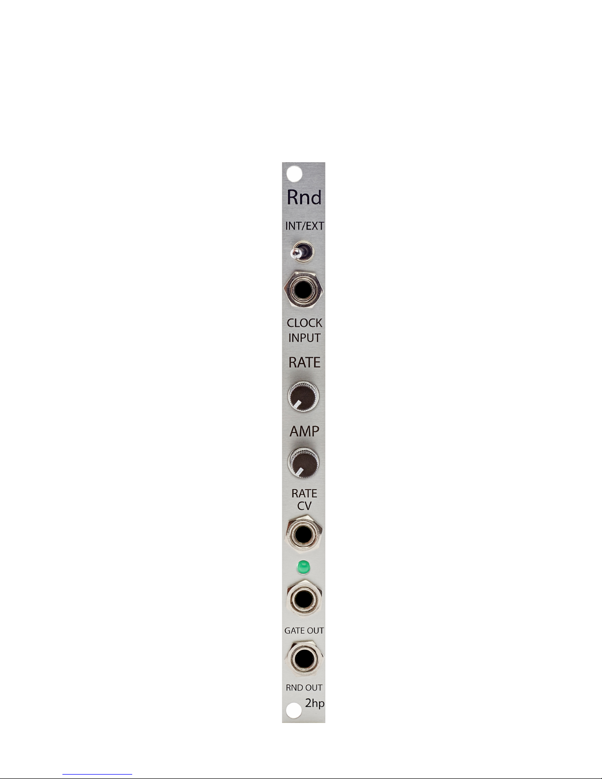
Rnd
Random Voltage Generator
Page 2

2
Description
Rnd is a random voltage generator and random gate source with an internal clock. The
output is a quantized random voltage between 0V and 10V. The attenuator control
provides fine-tuning of the random voltage. This allows for a musically useful range to
be defined. In addition, random gates are emitted from the gate output with an
associated probability control while externally clocked. Great for modulation and
chaotic rhythmic events, Rnd is a universal solution for adding unpredictability to your
system.
Page 3

3
Table of Contents
Installation/Specifications 4
Rnd 5
General Functions Overview 6
Page 4
4
Installation
To install, locate 2 HP of space in your Eurorack case and confirm the positive
12 volts and negative 12 volts sides of the power distribution lines.
Plug the connector into the power distribution board of your case, keeping in mind
that the red band corresponds to negative 12 volts.
In most systems the negative 12 volt supply line is at the bottom.
The power cable should be connected to the Rnd with the red band facing the
bottom of the module.
Specifications
Format: 2 HP Eurorack module
Depth: 34mm (Skiff Friendly)
Max Current: +12V = 40mA
-12V = 16mA
Page 5
5
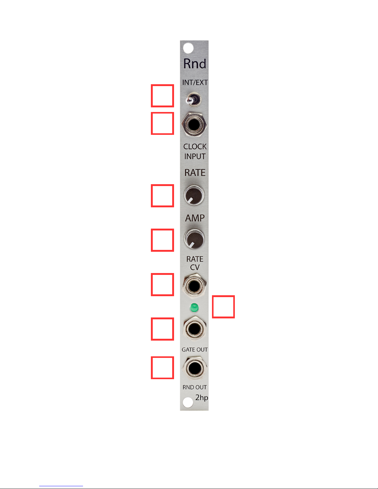
1 2 3 4 5 6 7
8
Page 6

6
General Functions Overview
1. INT/EXT:
Toggle that switches between the internal clock and an external clock.
If the toggle is in the left position, Rnd will be clocked at the rate of its internal clock
If the toggle is in the right position, Rnd will generate a new random voltage upon
receiving a gate or trigger signal at the CLOCK INPUT.
2. CLOCK INPUT:
If the INT/EXT toggle is in the left position, high voltage inserted into CLOCK INPUT
will freeze the random voltage emitting from RND OUT.
External clock input when the INT/EXT toggle is in the right position.
Threshold: 2.5V
3. RATE:
Internal clock rate control that changes the speed at which random voltage is
generated when the INT/EXT toggle is in the left position
Probability control of random gate signals when the INT/EXT toggle is in the right
position
INT Clock Mode
If the knob is far left, the internal clock rate will be as slow as possible.
If the knob is far right, the internal clock rate will be as fast as possible.
EXT Clock mode
If the knob is far left, the probability of the random gate signals will be as low as
possible
If the knob is far right, the probability of the random gate signals will be as high as
possible.
Page 7

7
4. AMP:
Amplitude control for the random voltage emitted from the RND OUT
If the knob is far left, random voltage will be fully attenuated (0V)
If the knob is far right, random voltage will be full scale (10V)
5. RATE CV:
Control voltage input for the rate of the internal clock
Range 0V – 8V
Control voltage is added to the knob position
6. LED:
LED that illuminates at the rate of the internal clock when the INT/EXT toggle is in the
left position
LED that illuminates when a random gate signal is emitted from the GATE OUT when
the INT/EXT toggle is in the right position
7. GATE OUT:
Output that will emit gate signals at the rate of the internal clock when the INT/EXT
toggle is in the left position
Output that will emit random gate signals when the INT/EXT toggle is in the right
position
8. RND OUT:
Output that will emit stepped random voltage at the rate of the internal or external
clock
Range: 0V – 10V (Max range dependent upon the AMP control)
 Loading...