

Page 1
LFO
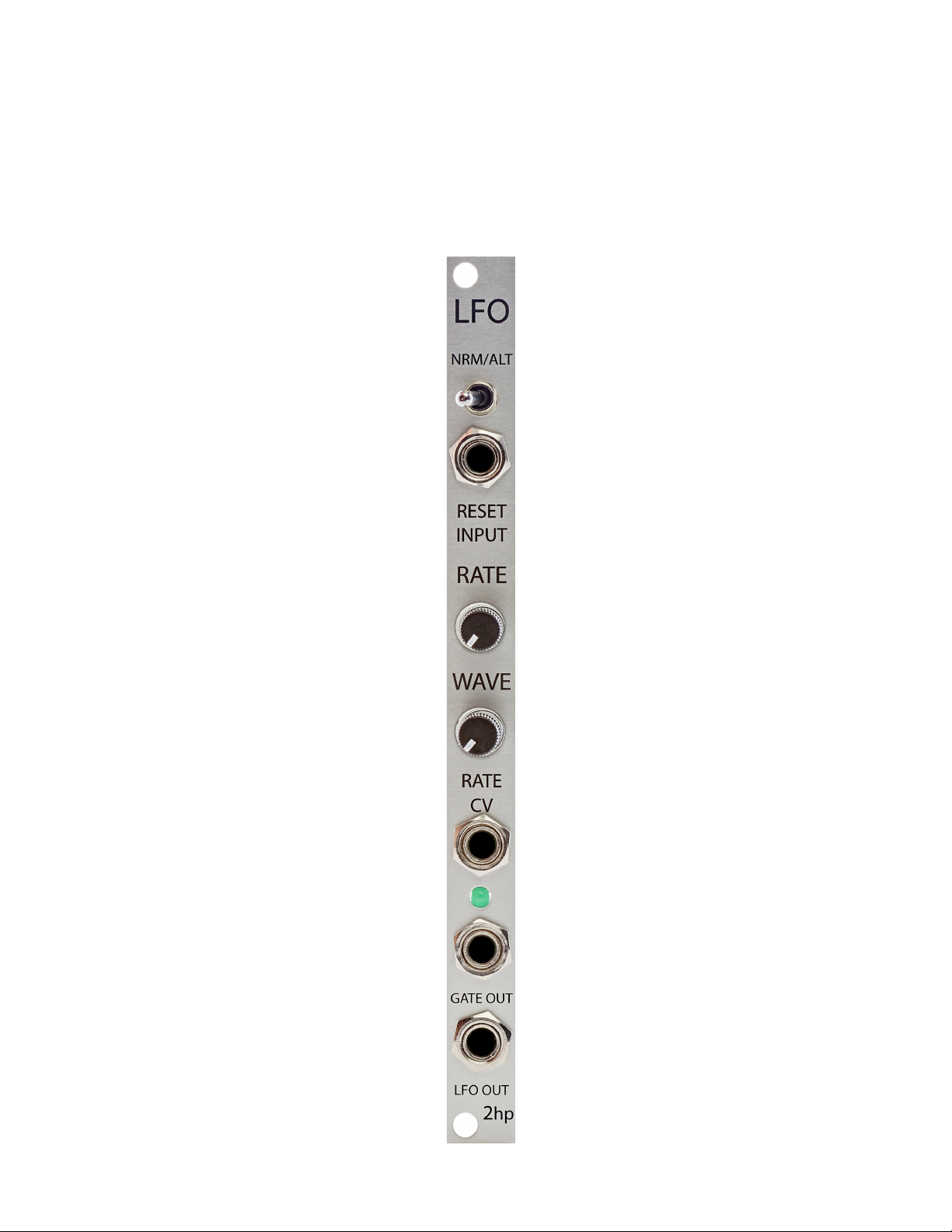
Morphing LFO
Page 2

2
Description
LFO is a voltage controlled, low frequency oscillator. 8 waveforms are available with
smooth morphing between each, allowing for complex and unique patterns. In addition
to sine, triangle, sawtooth, and square waveforms, four alternate waveforms are
accessible. The alternate waveforms have been designed with modulation in mind and
provide an innovative voltage source to use on filters, oscillators, and everything else.
If you’re looking to take your modulation to the next level, the 2hp LFO can get you
there.
Page 3

3
Table of Contents
Installation/Specifications 4
LFO 5
General Functions Overview 6
NRM Waveforms 8
ALT Waveforms 10
Page 4
4
Installation
To install, locate 2 HP of space in your Eurorack case and confirm the positive
12 volts and negative 12 volts sides of the power distribution lines.
Plug the connector into the power distribution board of your case, keeping in mind
that the red band corresponds to negative 12 volts.
In most systems the negative 12 volt supply line is at the bottom.
The power cable should be connected to the LFO with the red band facing the
bottom of the module.
Specifications
Format: 2 HP Eurorack module
Depth: 34mm (Skiff Friendly)
Max Current: +12V = 43mA
-12V = 16mA
Page 5
5
1 2 3
4 5 6 7 8
Page 6

6
General Functions Overview
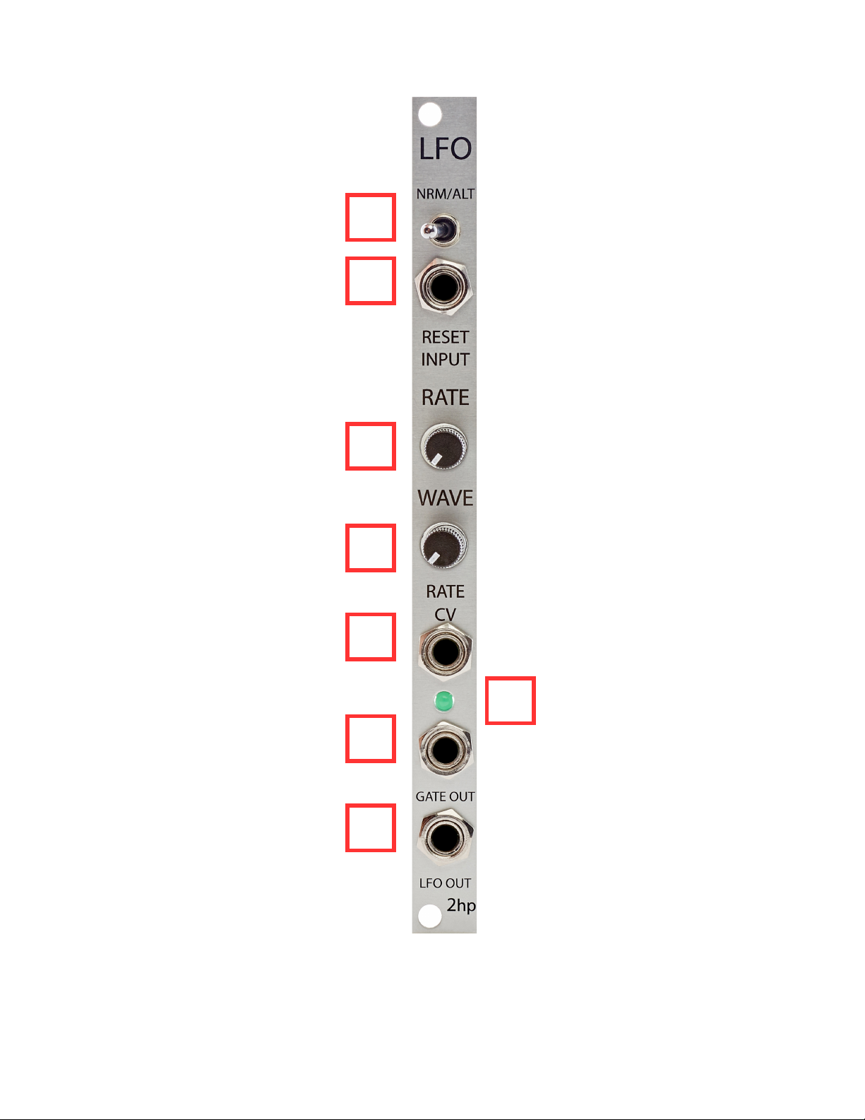
1. NRM/ALT:
Toggle that switches the output between standard and alternate waveforms.
(See 4. WAVE for a list of waveform shapes)
2. RESET INPUT:
Gate input that will reset the phase of the LFO to 0
Threshold: 2.5V
3. RATE:
Rate control of the LFO
If the Rate control is far left, the rate of the LFO will be as slow as possible
If the Rate control is far right, the rate of the LFO will be as fast as possible
4. WAVE:
Waveform control of the LFO
NRM Mode
The WAVE control smoothly interpolates between Sine, Triangle, Sawtooth, and
Square waveforms when the NRM/ALT toggle is in the left position
ALT Mode
The WAVE control smoothly interpolates between Phase Modulated Sines, Stepped
Triangle, Ramp, and Moustache waveforms when the NRM/ALT toggle is in the right
position
All waveforms are unipolar positive
Page 7

7
5. RATE CV:
Control voltage input for the rate of the LFO
Range: 0V – 8V
Control voltage is added to the knob position
6. LED:
LED that illuminates at the rate of the LFO
7. GATE OUT:
Output that emits gate signals at the rate of the LFO
This can also be thought of as an additional Square wave LFO output
8. LFO OUT:
Output of the currently selected LFO waveform
Minimum LFO rate = 0.096 Hz
Maximum LFO rate = 10.75 Hz
Page 8
8
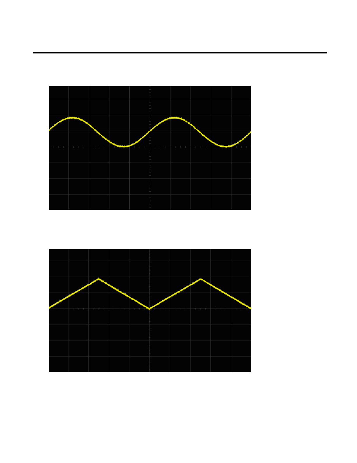
NRM Waveforms
Sine
Triangle
Page 9
9
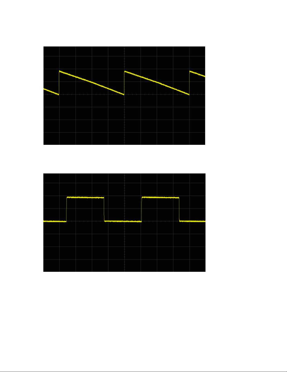
Sawtooth
Square
Page 10
10
ALT Waveforms
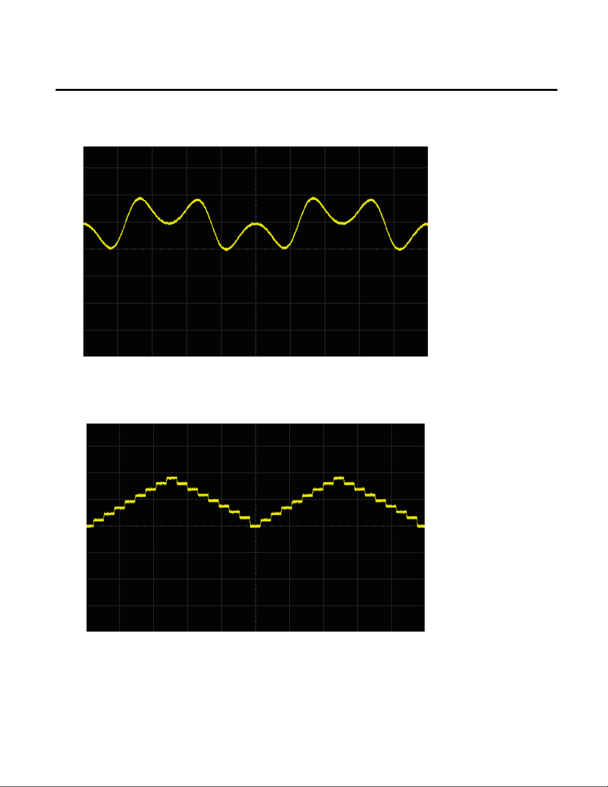
Phase Modulated Sines
Stepped Triangle
Page 11
11
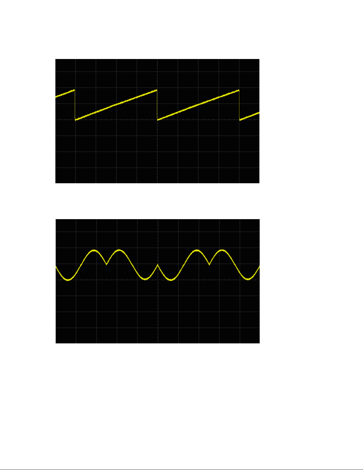
Ramp
Moustache
 Loading...