

Page 1
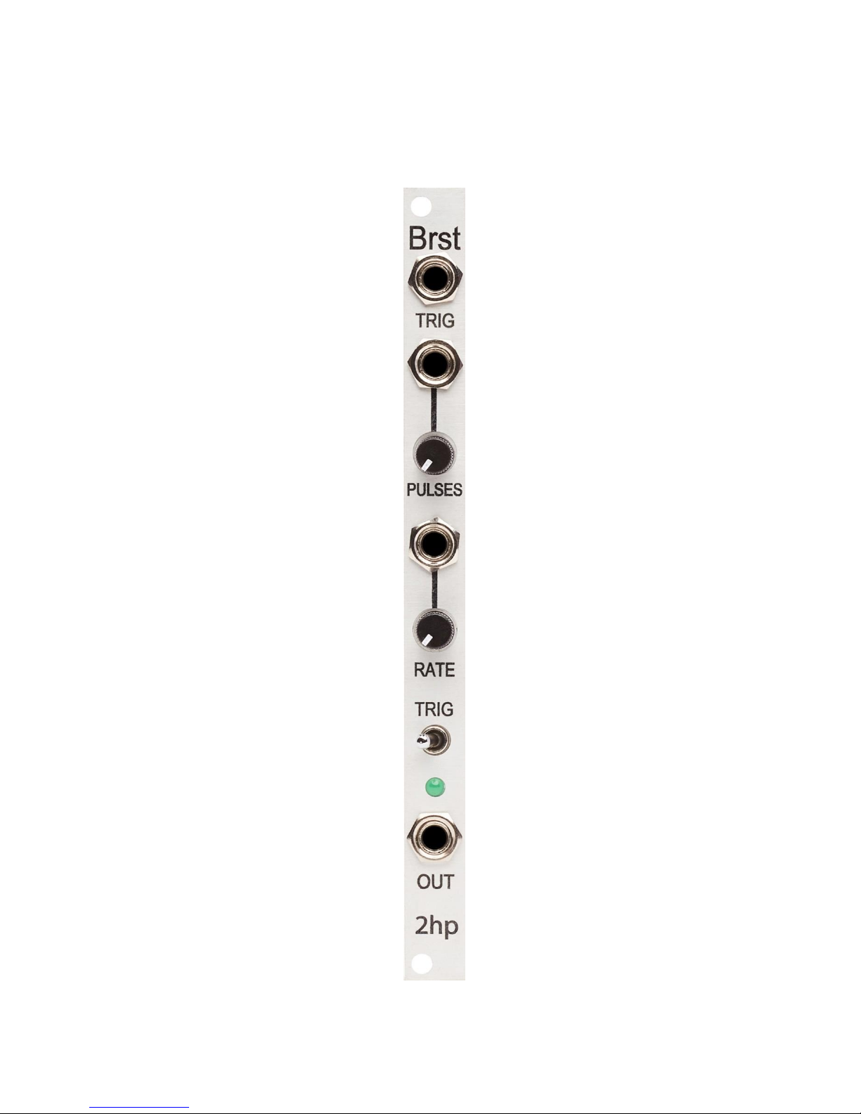
Brst
Page 2

2
Description
Brst is a voltage controlled burst generator and trigger delay. Upon receipt of a gate
signal, Brst will output a stream of triggers. Knobs and CV inputs give the user control
over speed and the number of repetitions. Whether you're generating bouncing balls,
crafting IDM drum beats, or humanizing a clock signal, Brst will prove an indispensable
addition to your rack.
• Voltage controlled burst generator
• CV over number of pulses and rate of output
• Initial trigger can be included or omitted from output
• Wide burst range all the way up to 32 repeats
Page 3

3
Table of Contents
Installation/Specifications 4
Brst 5
General Functions Overview 6
Page 4

4
Installation
To install, locate 2 HP of space in your Eurorack case and confirm the positive 12 volts
and negative 12 volts sides of the power distribution lines. Plug the connector into the
power distribution board of your case, keeping in mind that the red band corresponds
to negative 12 volts. In most systems, the negative 12 volt supply line is at the bottom.
The power cable should be connected to the Brst with the red band facing the front of
the module.
Specifications
Format: 2 HP Eurorack module
Depth: 47mm (Skiff Friendly)
Max Current: +12V = 26mA
-12V = 7mA
Page 5
5
1
2
3
4 5 6 7 8
Page 6

6
General Functions Overview
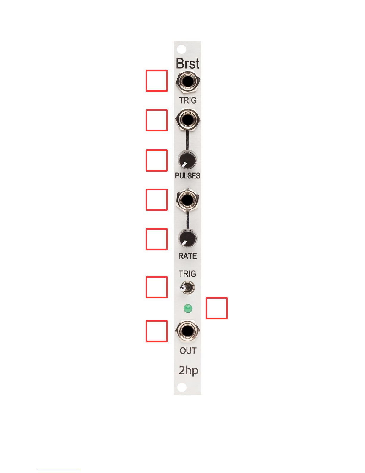
1. TRIG:
Trigger input
A stream of trigger signals will emit from OUT when a trigger or gate signal is received
at the TRIG input
Threshold: 2.5V
2. PULSES CV:
Control voltage input for PULSES
Control voltage is added to the knob position
Range: 0V – 5V
3. PULSES:
Controls the number of pulses that output when a trigger or gate signal is received by
the TRIG input
If the knob is far left, the number of pulses will be set to 1
If the knob is far right, the number of pulses will be set to 32
4. RATE CV:
Control voltage input for RATE
Control voltage is added to the knob position
Range: 0V – 5V
5. RATE:
Controls the delay time in between successive pulses
If the knob is far left, the delay time in between successive pulses will be set to 10ms
If the knob is far right, the delay time in between successive pulses will be set to
500ms
Page 7

7
6. TRIG TOGGLE:
Toggle that will include or omit the initial trigger signal
If the toggle is left, the initial trigger signal will be included
If the toggle is right, the initial trigger signal will be omitted
It important to note that if the TRIG TOGGLE is right and the PULSES knob is set to 1,
one pulse will emit from OUT and will be delayed by 10ms
7. BURST LED:
LED that indicates the pulses emitted from OUT
8. OUT:
Burst output
Range: 0V – 5V
 Loading...