


WaveBuddy WLAN Access Point
User Guide
EWP-645WA1
Version 1.0

11Wave Tec h no log y In c
INFORMATION TO USER
Federal Communications Commission Statement
This product has been tested and complies with the specifications for a Class B digital device,
pursuant to Part 15 of the FCC Rules. These limits are designed to provide reasonable protection
against harmful interference in a residential installation. The antenna used for this transmitter
must be installed to provide a separation distance of least 20 centimeters from all persons and
must operate in conjunction with other antenna or transmitters. This equipment generates, uses,
and can radiate radio frequency energy and, if not installed and used according to the instructions,
may cause harmful interference to radio communications. However, there is no guarantee that
interference will not occur in a particular installation. If this equipment does cause harmful
interference to radio or television reception, which is found by turning the equipment off and on,
the user is encouraged to try to correct the interference by one or more of the following measures:
◇ Reorient or relocate the receiving antenna
◇
◇ Connect the equipment to an outlet other than receiver’s
Notice: The Part 15 radio device operates on a non-interference basis with other devices operating
at this frequency. Any change or modification not expressly approved by the party responsible
could void the warranty.
Regulatory
The wireless LAN Card must be installed and used in strict accordance with the manufacturer’s
instructions. This device complies with the following radio frequency and safety standards.
USA - Federal Communications Commission (FCC)
This device complies with Part 15 of FCC Rules. Operation is subject to the following two
conditions:
1. This device may not cause harmful interference
2. This device must accept any interference that may cause undesired operation
Europe - R&TTE Directive
This device complies with the specifications listed below:
⌧
⌧ETS 300-328 Technical requirements for Radio equipment
⌧
EU Countries not intended for use
The ETSI version of this device is intended for home and office use in Austria, Belgium,
Denmark, Finland, France (with Frequency channel restrictions). Germany, Greece, Ireland, Italy,
Luxembourg, Netherlands, Portugal, Spain, Sweden and United Kingdom.
The ETSI version of this device is also authorized for use in EFTA member states Iceland,
Liechtenstein, Norway and Switzerland.
Increase the separation between the equipment or device
◇
Consult a dealer or an experienced radio/TV technician for assistance
ETS 300-826 General EMC requirements for Radio equipment
EN60950 Safety requirements for Radio equipment
I

11Wave Tec h no log y In c
Table of Contents
Section 1. Introduction.................................................................................................................1
1.1 The WaveBuddy WLAN Access Point ......................................................................................1
1.2 Package Contents .......................................................................................................................1
1.3 System Requirements.................................................................................................................1
1.4 Features .. ………………………………………………………………………………………1
1.4.1 Firmware Features................................................................................................................1
1.4.2 Bridging Functions...............................................................................................................2
1.4.3 Management .........................................................................................................................2
1.4.4 Roaming ...............................................................................................................................2
1.4.5 Operation Modes ..................................................................................................................2
1.5 Network Interface ......................................................................................................................2
Section 2. Network Configuration and Planning.......................................................................3
2.1 Wireless LAN Basic...................................................................................................................3
2.2 Network Topology .....................................................................................................................3
Section 3. Installation Overview..................................................................................................6
Section 4.
4.1 Using the Ethernet Port/Wireless Port .....................................................................................11
4.1.1 Using ARP/Ping commands...............................................................................................11
4.1.2 DHCP client .......................................................................................................................12
4.2 Using the USB Port..................................................................................................................12
Section 5.
5.1 Using the SNMP Configuration Utility application.................................................................14
5.1.1 Connecting to the Access Point..........................................................................................14
5.1.2 Configuring the Access Point .............................................................................................16
5.1.3 Reset the AP by manual......................................................................................................28
5.2 Using Web Browser .................................................................................................................28
5.2.1 Connecting the WaveBuddy-AP To Your Network ............................................................29
5.3 Using the DFU Utility application...........................................................................................36
Section 6.
6.1 Using the SNMP Configuration Utility application.................................................................41
6.2 Using Web Browser .................................................................................................................42
6.3 Using the DFU Utility application...........................................................................................42
Appendix A ……………………………………………………………………………………...45
Appendix B: Glossary ..................................................................................................................47
Setting the IP Address of the Access Point ..............................................................11
Access Point Configuration......................................................................................14
Access Point Firmware Upgrade .............................................................................41
II

11Wave Tec h nol ogy I nc
Section 1. Introduction
1.1 The WaveBuddy WLAN Access Point
The WaveBuddy WLAN Access Point (WaveBuddy-AP) is a long-range, high performance LAN
product, which provides Access Point services to a 2.4 GHz RF network and bridges to an
Ethernet backbone.
This document describes the steps required for the initial set up of the AP IP Address, the AP
configuration, and the firmware upgrade procedure. The description includes the implementation
of the above steps through Ethernet, USB and any current Web Browser, i.e., Internet Explorer 5x,
Netscape Navigator 4x or above.
1.2 Package Contents
Please make sure that your received the following with:
♦
One WaveBuddy Access Point
♦
One Software Tools CD (Drivers and User Guide on CD)
♦ One USB cable
♦ One Ethernet cable (crossover)
♦ One power adapter
1.3 System Requirements
For configuration through USB:
♦
Operating System: Windows 98se/Me/2000/XP
♦
Desktop PC or notebook PC with USB port
For configuration through Ethernet:
♦Operating System: Windows 95/98/98se/Me/2000/XP, Windows® NT 4.0
♦
Desktop PC or notebook PC connected on a LAN
1.4 Features
1.4.1 Firmware Features
The IEEE 802.11b firmware implementation for the WaveBuddy-AP supports:
– High data rate 11/5.5/2/1 Mbps
– Auto Rate fallback
– Basic Rate Set
– Distributed Coordination Function
– CSMA/CA
– Backoff Procedure
– NAV Management
– ACK Procedure
1

11Wave Tec h nol ogy I nc
– Retransmission of unacknowledged frames
– RTS/CTS Handshake
– Duplicate Detection and Recovery
– Beacon Generation
– Probe Response
– Fragmentation and Reassembly
– Wired Equivalent Privacy Algorithm (WEP 64, 128 bits)
– Authentication Algorithm (Open System, Shared Key)
– Power Management
– Association, Re-association and Disassociation
– Support for 802.1x in AP mode (Tested only with Microsoft Internet Authentication Servers
using EAP-TLS)
1.4.2 Bridging Functions
The following bridging functions are supported:
– Automatic Learning Process
– Filtering Database
– Forwarding Process
– IP Filtering
– Authorized Table
– Aging Function
– Protocol Filtering
1.4.3 Management
For Bridge Management, WaveBuddy-AP supports:
– SNMP (Wireless MIB, traps, firmware upgrade)
– USB (DFU-configuration, firmware upgrade)
–WEB Server for Configuration and Upgrade purposes
– Set IP Session (ARP/Ping)
– DHCP client
– Default Gateway
1.4.4 Roaming
Roaming functions supported:
– Among APs on the same subnet
– Preferred AP (only on WaveBuddy Bridge)
1.4.5 Operation Modes
Operation Modes supported:
– Access Point
– Access Point Client
– Wireless Bridge
– Wireless Repeater
1.5 Network Interface
WaveBuddy-AP supports 10 Mbps network interface.
2
11Wave Tec h nol ogy I nc
Section 2. Network Configuration and
Planning
2.1 Wireless LAN Basic
The WLANs support legacy Ethernet LAN network configuration options as defined by the IEEE
802.11b standards committee. The wireless LAN card/adapter can be configured as:
♦ Ad-Hoc for departmental or SOHO LANs
♦ Infrastructure for enterprise LANs
♦
LAN-Interconnection for point-to-point link as campus backbone
2.2 Network Topology
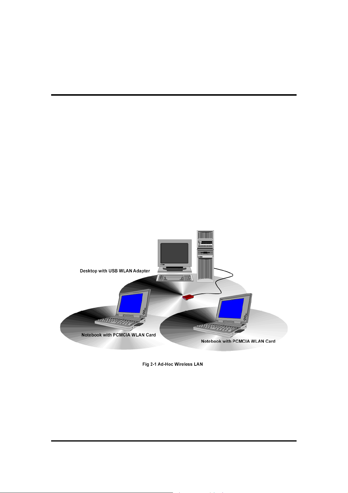
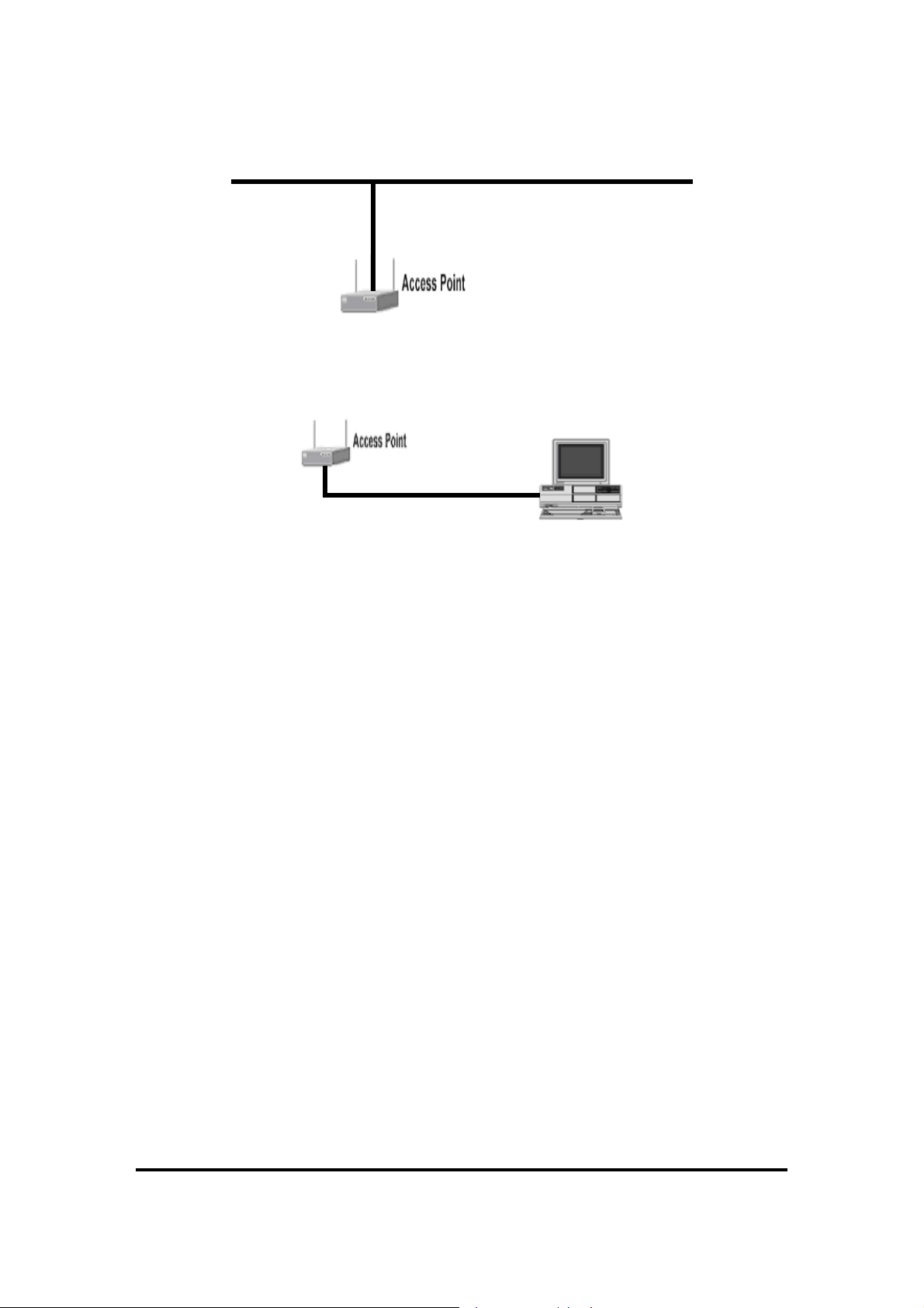
An Ad-Hoc wireless LAN is a group of computers shown in Fig2.1, each equipped with one
WLAN card/adapter, connected as an independent wireless LAN. Computers in a specific
Ad-Hoc wireless LAN must be configured to share the same radio channel.
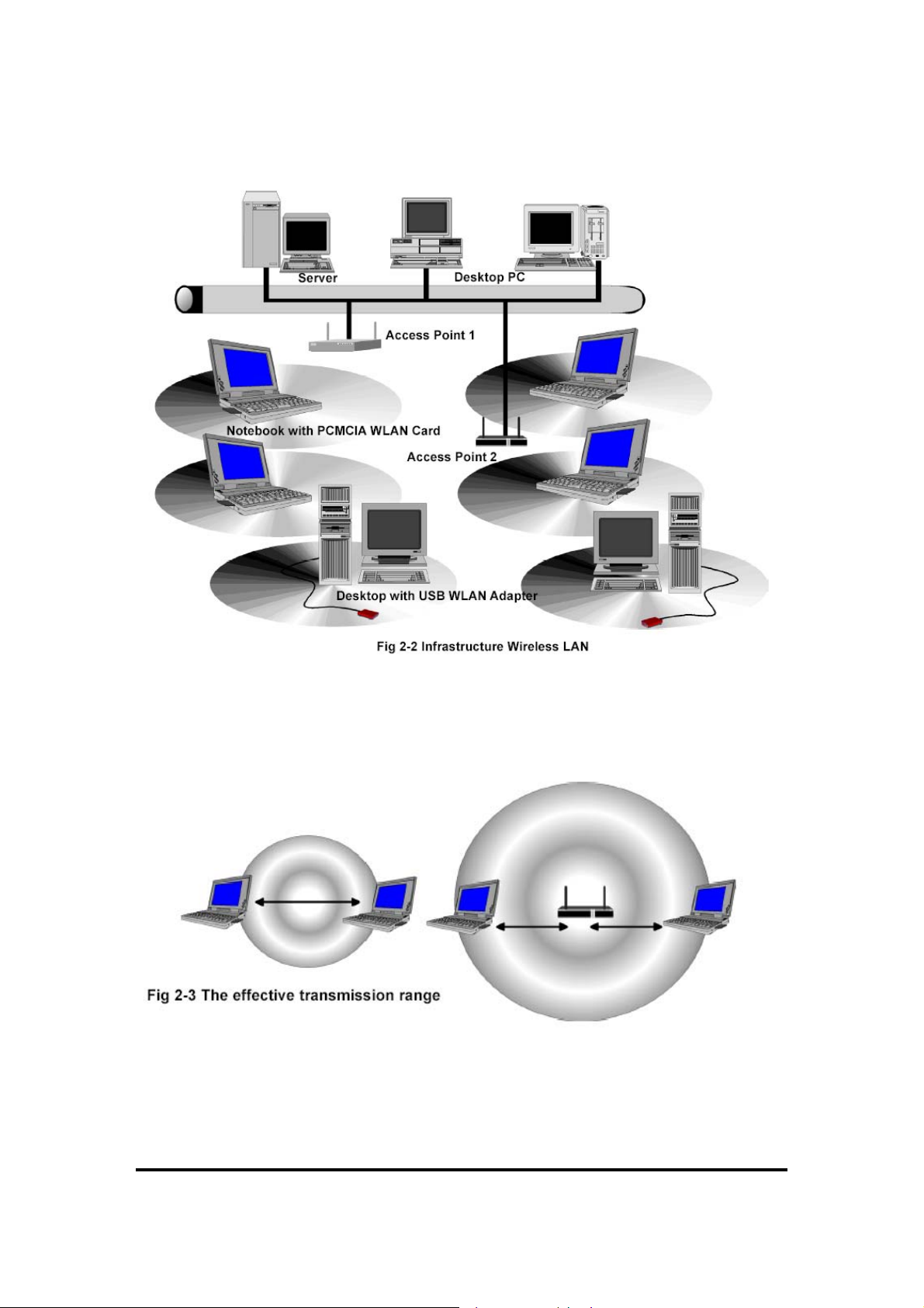
The card/adapter provides access to a wired LAN for wireless workstations. An integrated
wireless and wired LAN is called an infrastructure configuration shown in Fig 2.1. A group of
WLAN PC users and an Access Point compose a Basic Service Set (BSS). Each WLAN PC in a
BSS can talk to any computer in the wired LAN infrastructure via the Access Point.
3
11Wave Tec h nol ogy I nc
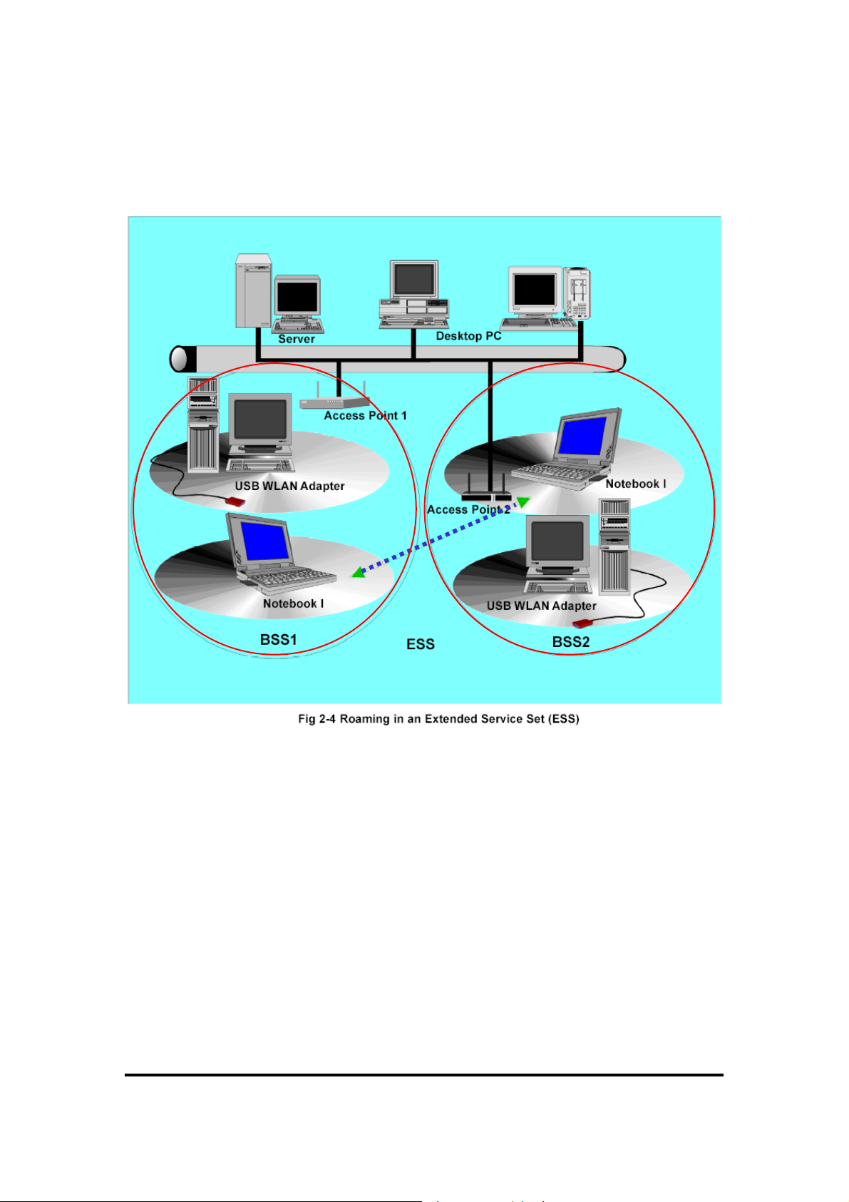
An infrastructure configuration extends the accessibility of a WLAN equipped PC to a wired
LAN, and doubles the effective wireless transmission range for 2 WLANs PCs. Since the Access
Point is able to forward data within its BSS, the effective transmission range in an infrastructure
LAN is double shown in Fig 2.3.
The use of a unique ID in a BSS is essential. All WLAN equipped PCs configured without
roaming options in independent BSS must be configured with a BSS ID corresponding to the
Access Point used in the BSS. Check your Access Point for its BSS ID or use the Access Point
Utility program to determine the BSS ID. The infrastructure wireless LAN configuration is
4
11Wave Tec h nol ogy I nc
appropriate for enterprise-scale wireless access to a central database, or as a wireless application
for mobile users.
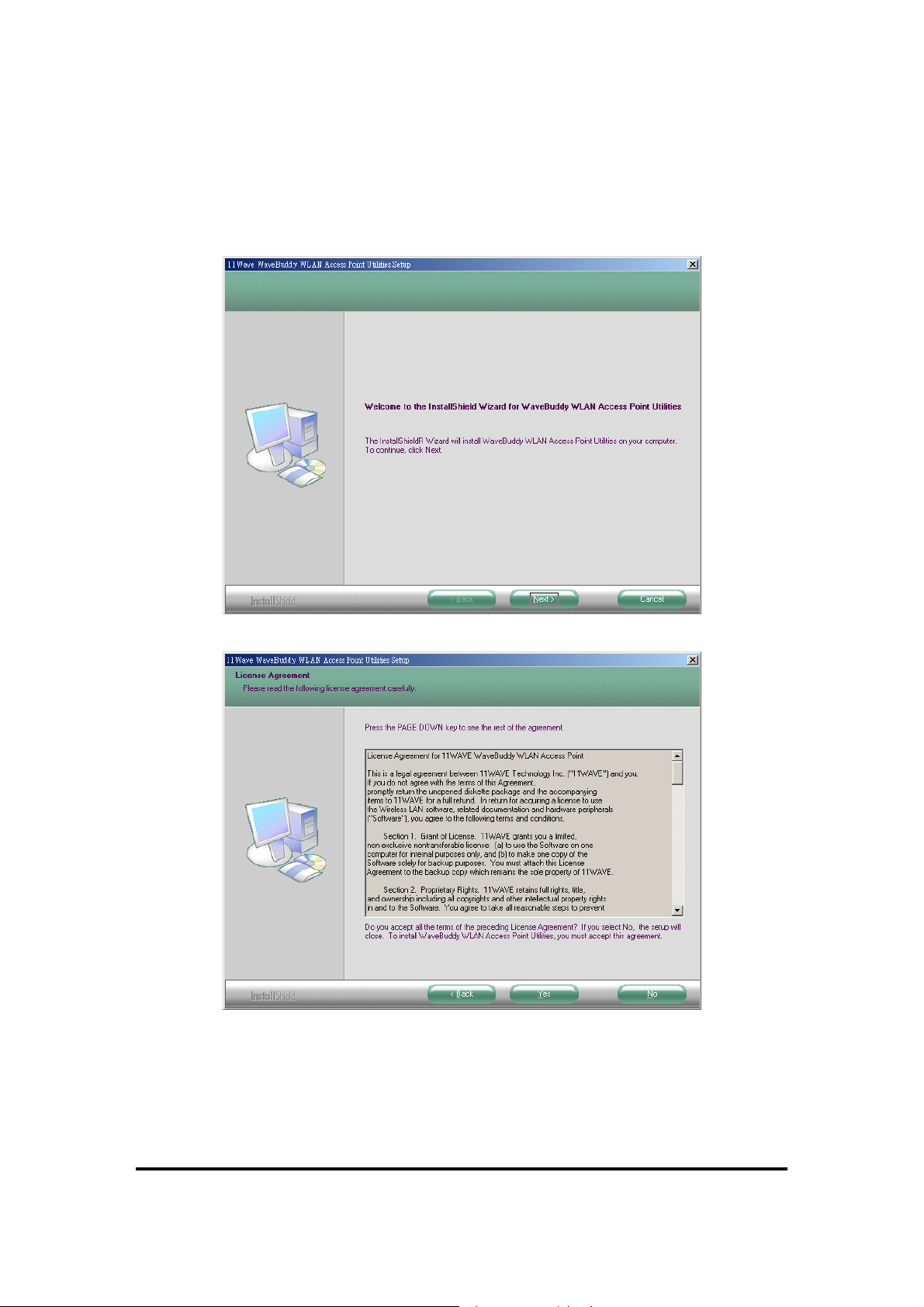
Infrastructure mode also supports roaming capabilities for mobile users. More than one BSS can
be configured as an Extended Service Set (ESS) shown in Fig 2.4. The continuous network
allows users to roam freely within an ESS. All WLAN PCs and Access Point within one ESS
must be configured with the same ESS ID.
Before enabling an ESS with roaming capability, it is recommended to select a feasible radio
channel and optimum Access Point position. Proper Access Point positioning combined with a
clear radio signal will greatly enhance performance.
5

11Wave Tec h nol ogy I nc
Section 3. Installation Overview
This section provides a quick step-by-step guide on how to install your WaveBuddy WLAN
Access Point. Please follow the steps described below.
1. Power on the computer.
2. Install the drivers and application:
Step 1.
Insert the given Installation CD into your CD-ROM driver. Unless you have
deactivated the autorun feature of the window, the screen shown as below should
appear automatically. If this screen doesn’t appear automatically, you can access
the installation by clicking the
drop-down box provided type
CD-ROM drive). Alternately, double-click “My Computer” and double-click the
Autorun.exe
and go to
icon in the folder that appears or browse to your CD-ROM drive
D:\WLAN Access Point\AP Utility\
Autorun
D:\Autorun.exe
button and choosing
and click on the
(where D: is the letter of your
Run
Setup.exe
. In the
.
Step 2.
Click the “
installation process.
Install AP Utility
” button to start the driver and application
6
11Wave Tec h nol ogy I nc
Step 3.
Follow the installation instructions from the InstallShield Wizard by pressing the
Next
“
” button.
7
11Wave Tec h nol ogy I nc
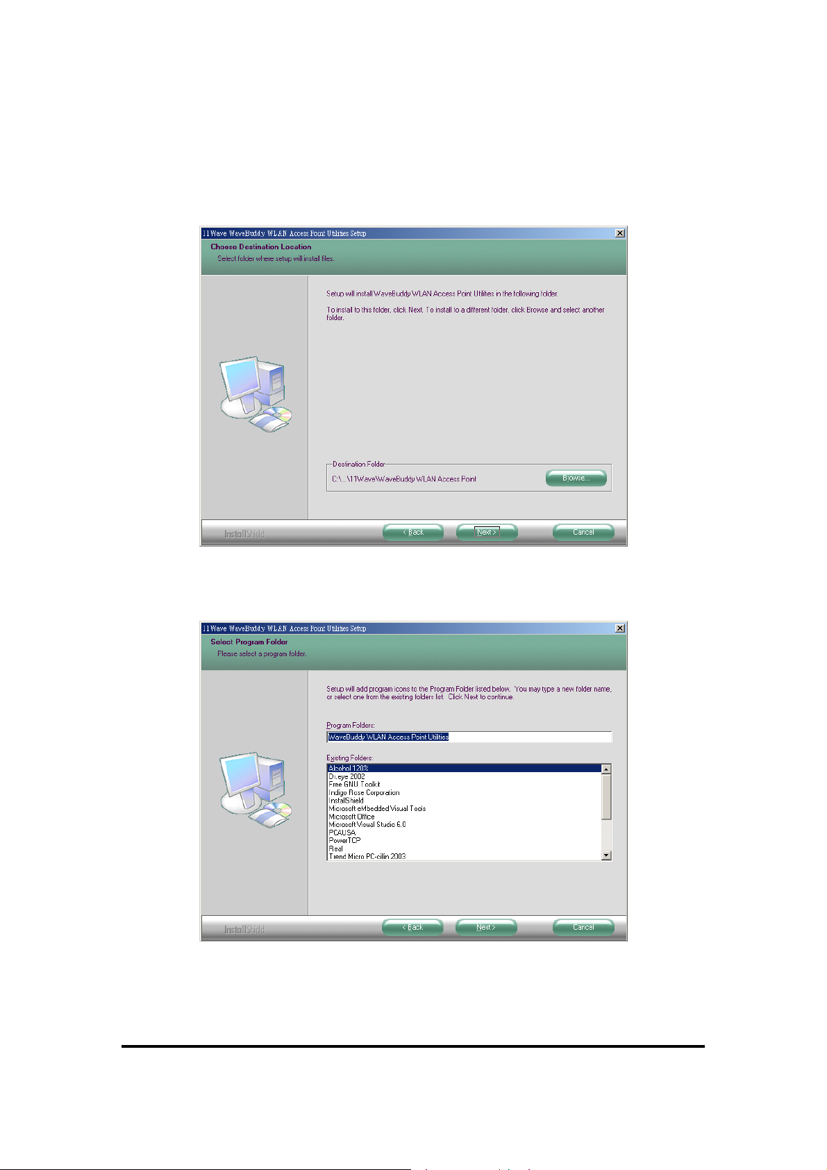
Step 4.
Give the destination path where the application will be installed. To set the path
of your choice, select “
Browse
” and click “
Next
”.
Step 5.
Select a program folder and then select “
Next
”.
8
11Wave Tec h nol ogy I nc
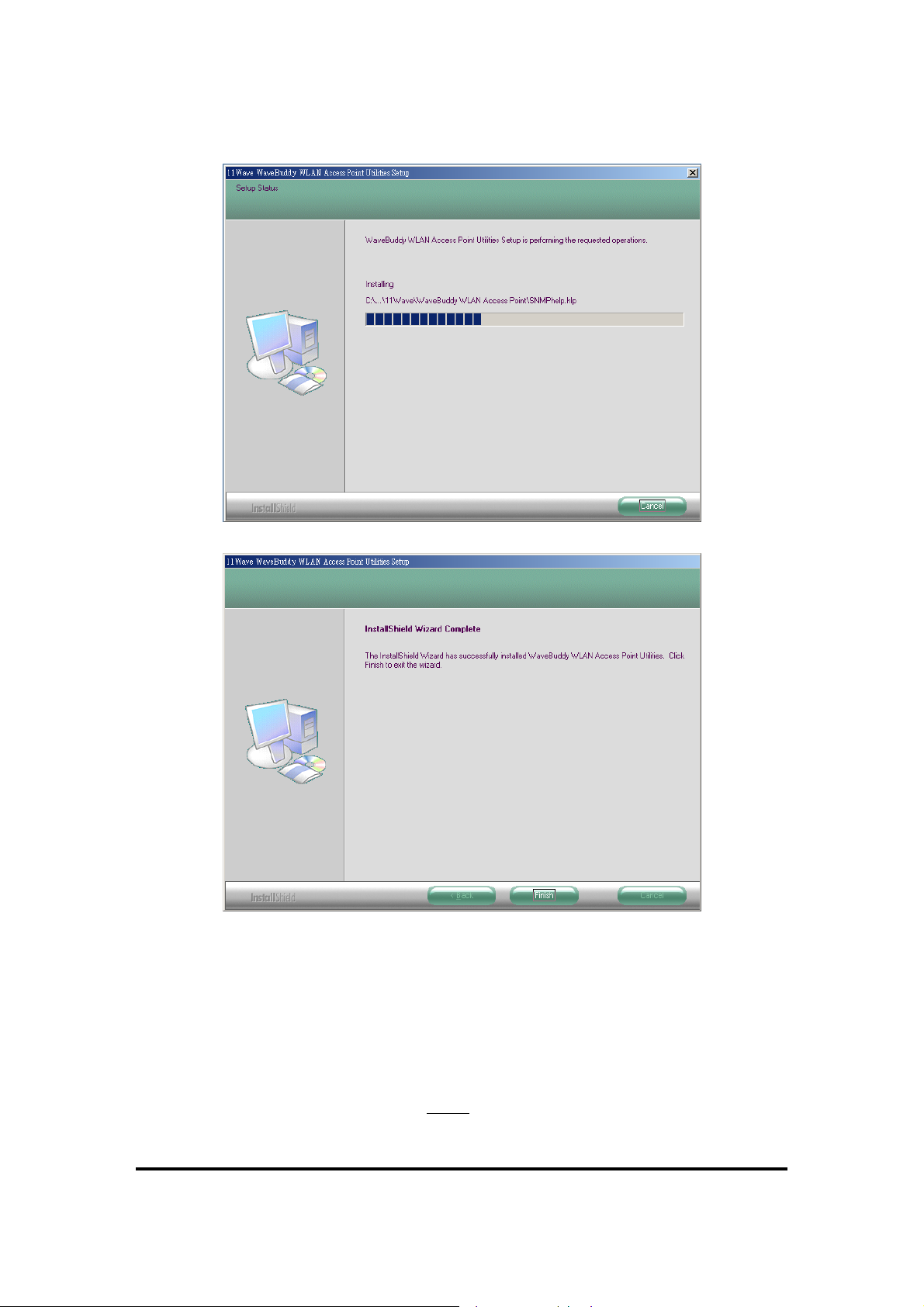
Step 6. Finish the installation. If prompted for reboot, select “Yes”.
3. Connect and operate the Access Point
Adjust the Access Point antennas.
Connect the Ethernet cable from the wired 10/100 Ethernet LAN to the Ethernet connector on
the Access Point. (Make sure to do this before
you apply power to the Access Point).
9
11Wave Tec h nol ogy I nc
Ethernet cable
Note:
When you connect the Ethernet cable from the wired 10/100 Ethernet network card of
LAN
PC to the Ethernet connector on the Access Point, you must use crossover Ethernet
cable.
Ethernet cable
(crossover)
Connect the power supply adapter by inserting the power pack connector into the power
receptacle on the back of the Access Point.
Read the MAC address from the label on the bottom of the Access Point (for example:
00-0B-10-02-00-1C).
From your system administrator obtain:
The ESSID for your radio network.
If not connected to a DHCP server, a unique IP address for the Access Point. If the Access
Point is not on the same subnet as your PC, a default gateway address and subnet mask.
Note: The “Add New Hardware Wizard” automatically loads the Drivers when the USB
cable connects to the Wireless-AP.
4. Associate an IP address with the Access Point
If you are connected to a DHCP server and the DHCP Client button on the Access Point is
enabled, the server will automatically assign an IP address when you connect the Access
Point to your network. You must identify the assigned address by using the Find Access Point
option in the SNMP Configuration Utility (SNMP Manager).
If you are not connected to a DHCP server and the AP is on the same subnet as your PC, you
can use the ARP/Ping commands to assign an IP Address to the AP. The default IP address of
the WaveBuddy-AP is
Note:
More detailed information is available in this User Guide, Section 4: “Setting the IP
Address of the Access Point”.
192.168.98.11
with a Subnet Mask of
255.255.255.0
.
10

11Wave Tec h nol ogy I nc
Section 4. Setting the IP Address of the
Access Point
The first step in using the WaveBuddy-AP is to set its IP Address. The default IP address of the
WaveBuddy-AP is
done through the Ethernet/Wireless port by using a combination of ARP/Ping commands and the
SNMP Configuration Utility application (SNMP Manager), or by using the network DHCP server.
It also can be done through the USB port by using the DFU Utility application (AP Utility)
192.168.98.11
with a Subnet Mask of
4.1 Using the Ethernet Port/Wireless Port
You can set the AP IP Address using the ARP/Ping commands or by using the network DHCP
server.
4.1.1 Using ARP/Ping commands
In order to set the AP IP Address you first need to know the AP MAC Address (the MAC
Address of the AP is indicated on the back of the AP board). Follow the steps below to give the
AP a temporary IP Address at the beginning (Step A) and then save the IP Address through the
SNMP Configuration Utility application (SNMP Manager)(Step B).
Step A:
1. Connect an Ethernet station and the AP on the same subnet
that is to connect the AP and the Ethernet station to the same hub. You need to check if the
station IP Address and the Subnet mask are configured properly. Also, the new IP Address
for the AP must correspond to the Subnet mask.
2. Open an MS-DOS Prompt window and enter a static route in the ARP table for the new IP
Address you want to assign. Use the ARP -s command to do that:
ARP -s “new-IP-Address” "AP-MAC-Address"
For example
3. Ping the AP, using its new IP Address.
For example
If you get a ping reply, then the IP Address has been temporarily set. In order to set it
permanently you need to proceed to Step B without powering off
Step B:
1. Open the SNMP Configuration Utility application (SNMP Manager).
2. Connect to the AP by selecting the “Connect to Access Point” option under the “File” menu.
Type the IP Address of the AP (which has been temporarily set in Step A) in the panel which
appears, type “
combo-box and then press OK. The AP Configuration application will inform you that the AP
has been found and that all the configuration values have been successfully retrieved.
: ARP -s 192.168.98.33 00-0B-10-02-00-1C
: ping 192.168.98.33
public
” at the Community field, select “
255.255.255.0
. The simplest way to accomplish
Administrator
. This procedure can be
the AP.
” in the Authority
11
11Wave Tec h nol ogy I nc
3. Select the Setup | Bridge | IP Configuration. Type the IP Address of Step A in the
configuration window that appears. Confirm the validity of the other values (MAC Address
and IP Mask), and select the Primary Port that determines the AP’s MAC Address and IP
Address and press “OK”.
4. Save the configuration by selecting
File | Download Changes
. The IP Address of the AP has
now been set permanently.
4.1.2 DHCP client
If DHCP client is enabled, the IP Address field displays the IP Address that was dynamically
assigned to the AP by the network DHCP server. The IP Mask field displays the IP Mask utilized
by the network DHCP server. Select the Primary Port, which is the interface that determines the
DHCP server, and press “OK”. If the network server failed to give an IP Address to the AP, then
the AP IP Address is the default one.
4.2 Using the USB Port
This procedure requires the use of the DFU Utility application (AP Utility) that can be used only
through the USB port. When you connect the WaveBuddy-AP to the USB port for the very first
time, the operating system will automatically detect the device since the driver has been already
installed during the installation process.
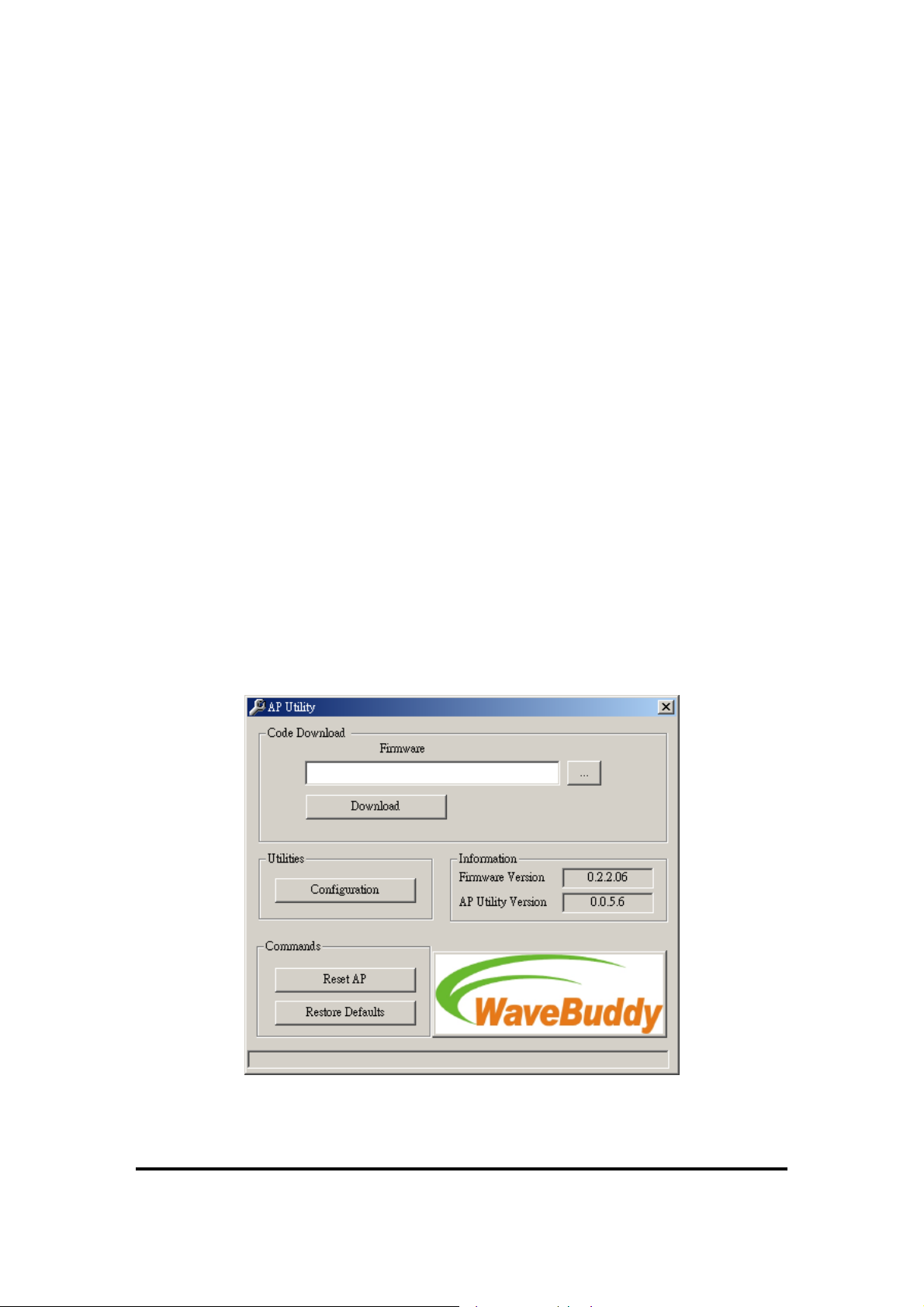
Plug the USB cable to the WaveBuddy-AP USB port. Run the DFU Utility application and select
the “Configuration” button (Figure 4-1).
Figure 4-1.
DFU Utility application (AP Utility)
12

11Wave Tec h nol ogy I nc
In the window that appears, press the “Get” button if you want to view the current IP Address
(Figure 4-2). If you want to set a new IP Address, first select the parameter “Eth_IP_Address”,
then press the “Modify” button and then type the new IP Address that appears in the window.
Press the “Set” button for the changes to take effect.
Figure 4-2.
Bridge Configuration
13

11Wave Tec h nol ogy I nc
Section 5. Access Point Configuration
The WaveBuddy-AP configuration can be done either through the Ethernet/Wireless port by
using the SNMP Configuration Utility (SNMP Manager) application and Web Browser, or
through the USB port by using the DFU Utility application (AP Utility).
5.1 Using the SNMP Configuration Utility application
Before using the SNMP Configuration Utility (SNMP Manager) application for configuring the
WaveBuddy-AP, verify that the WaveBuddy-AP’s IP Address has been set following the
procedure described in the Section 4 “Setting the IP Address of the Access Point”. The default IP
address of the WaveBuddy-AP is
5.1.1 Connecting to the Access Point
On the window task bar, choose
SNMP Configuration Utility to open the application.
File menu:
Connect to Access Point -
type its IP Address in the panel that appears (Figure 5-1). Then, type the appropriate
password in the Community field (see Section 5.1.2 • Setup menu • Authorization
option. The default password is "
Administrator Authority in the Authority combo-box. User Authority allows you to
view but not to set or save changes to the AP Configuration, while Administrator
Authority allows you to either view or set changes to the AP Configuration. Press
“OK” to finish.
The File Menu contains the following options:
192.168.98.11
Start | Programs | WaveBuddy WLAN Access Point Utilities |
Using this option you can directly connect with the AP. First,
with a Subnet Mask of
public
"). Finally, you have to select either User or
255.255.255.0
.
Figure 5-1. Connecting to the Access Point
14
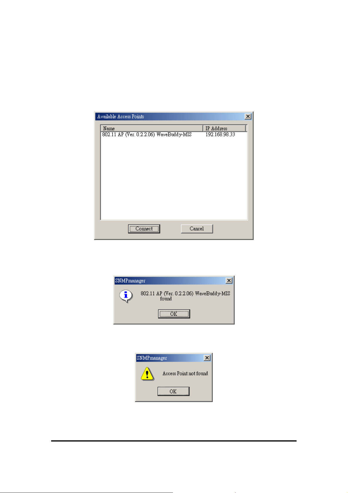
Find Access Point -
11Wave Tec h nol ogy I nc
This option allows you to find and connect with an AP without the
necessity of knowing its IP Address. Choose this option in order to find the APs
available for connection (Figure 5-2). Select one of the available APs and press
“Connect”. Figure 5-1 appears indicating the IP Address of the selected AP and
prompting you to select Authority and to write the appropriate password at the
community field. Then press “OK”.
Figure 5-2.
Find the available Access Points
In case of a successful connection to the AP, the following window appears (Figure
5-3). Press “OK”.
Figure 5-3.
Access Point found
In case of an unsuccessful connection you receive the following message (Figure 5-4):
Figure 5-4.
Access Point not found
If the above error message appears, you need to check if the AP has the desired IP
15

11Wave Tec h nol ogy I nc
Address and is connected to the network. In order to check the validity of the IP
Address you need to ping the AP.
Firmware Upgrade –
Please refer to Section 6 “Access Point Firmware Upgrade” for
more details.
Exit -
Help menu:
Terminates the application.
Provides on-line help about the application.
5.1.2 Configuring the Access Point
When the connection has been successfully established, you will get a message in the left bottom
corner indicating as “Get Configuration done” and on the right bottom corner as the “IP Address”
of the connected AP.
File menu: The file menu contains the following enabled options:
Close Connection AP -
Terminates the connection with the AP.
Download Changes -
When all the desired values of the parameters have been set you
are able to download the changes (save the changes) to the AP by selecting this option.
Refresh -
Renews the display.
Options -
Defines the polling interval according to which the AP Configuration polls the
AP in order to update the statistics and the Associated Stations List.
Exit -
Setup menu:
Terminates the connection with the AP and exits the application.
As soon as the connection has been established, you are able to start
viewing or setting the AP parameters. Under the “Setup” menu, there are the following
submenus (Figure 5-5):
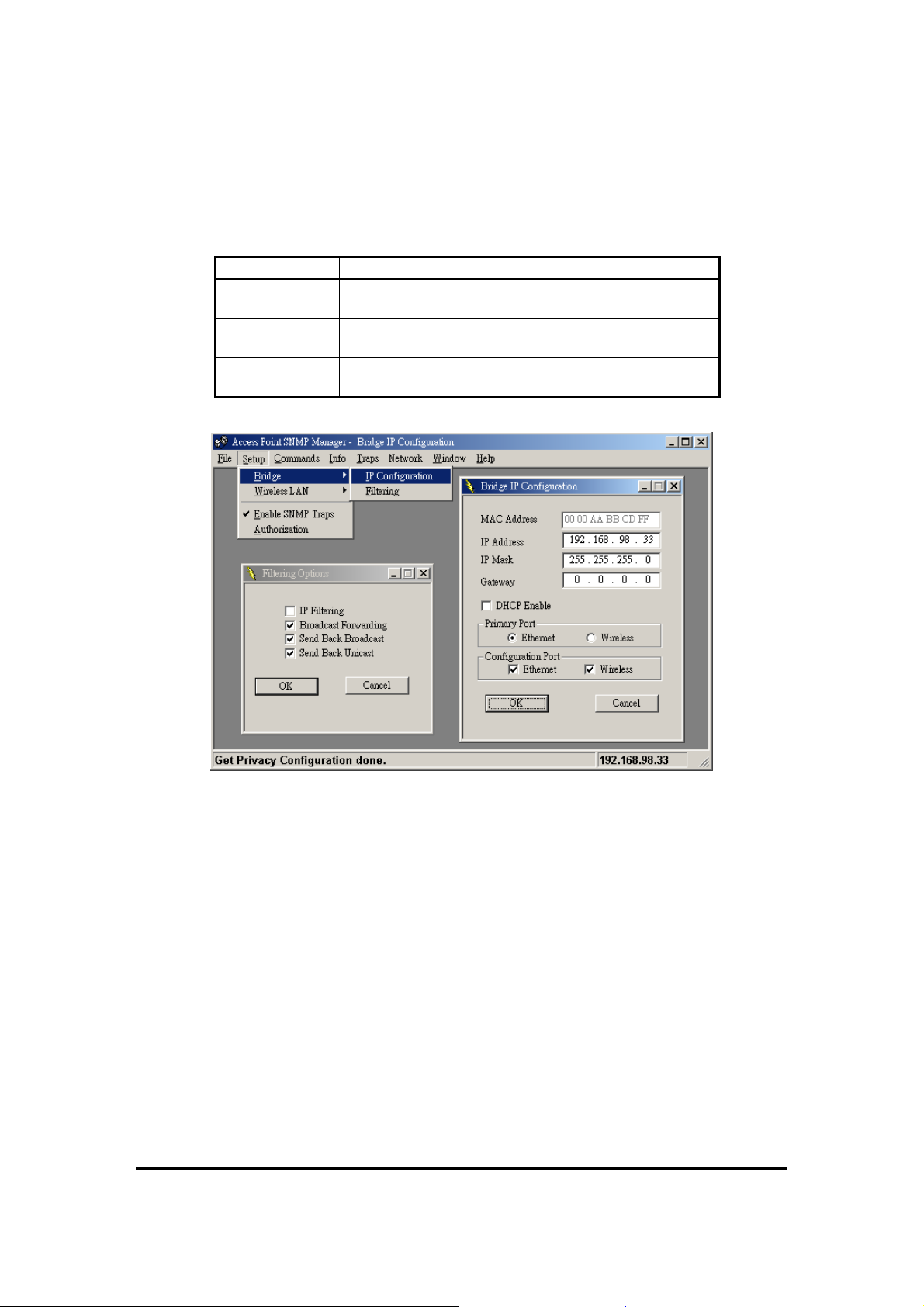
Bridge -
Under the “Bridge” submenu, there are two options:
IP Configuration: By choosing this option the window of Figure 5-5 appears. The “IP
Address” and “IP Mask” can be modified through “IP Configuration”, if DHCP client is
not enabled. If DHCP client is enabled the IP Address field displays the IP Address that
was dynamically assigned to the AP by the network DHCP server and the IP Mask field
displays the IP Mask utilized by the network DHCP server.
Additionally you have to select the Primary Port, which is the interface that determines
the DHCP server. Also, you can select which port (Ethernet Port and/or Wireless Port)
will be used for the AP configuration.
16
11Wave Tec h nol ogy I nc
If you make any changes, you need to select “Download Changes” under the “File” menu
in order to save them.
Table 5-1.
Bridge IP Configuration Parameters
Parameters Description
MAC Address Unique 48-bit, hard-coded Media Access Control
address known as the station identifier.
IP Address
IP Mask
Network-assigned Internet Protocol address of the
Access Point.
Four sets of three digits that divide a network into
subnetworks.
Figure 5-5.
Filtering:
(Figure 5-5).
Under this window you can set the filtering options that the AP will use
Bridge IP Configuration and Filter Options
IP Filtering:
protocol will be filtered out.
Only the IP protocol packets will pass through the WLAN and any other
Broadcast Forwarding:
The AP should not forward broadcast traffic to the air.
Send Back Broadcast:
The AP should not send back to the air broadcast traffic
received from the air.
Send Back Unicast:
from the air.
Wireless LAN -
The AP should not send back to the air unicast traffic received
Under this submenu the following three options are available (Figure
5-6).
17

11Wave Tec h nol ogy I nc
Figure 5-6. Access Point SNMP Wireless LAN menu and submenu
Privacy Options: By choosing this option you may download the encryption key values
using the Wireless Equivalent Privacy (WEP) Option Window (Figure 5-7). Write the
values and press “Set” to download (WEP key is write-only, so it is not possible to
retrieve the key values). There are four 5 Hex digit encryption keys available if you select
64bit WEP and there are four 13 Hex digit encryption keys available if you select 128bit
WEP. The key is enabled only if you select it in the “Default key” option. Enable the
WEP (Wired Equivalent Privacy) option in order to activate WEP encryption for
transmissions between the stations and the AP. WEP is an authentication algorithm that
protects authorized Wireless LAN users against eavesdropping.
Figure 5-7.
Wireless Privacy Option Window
18

11Wave Tec h nol ogy I nc
Notes:
The Authentication type must be the same on the Wireless Station and on the
AP. All shared keys on the Wireless Station must be the same as those on the
AP with which the client station is associated.
If you press the Advanced button on Figure 5-7, the following four options are
available (Figure 5-8).
Figure 5-8.
Advanced Wireless Privacy Options
♦ 802.1X Enable:
Enable, Disable, Mixed Environment.
When using Enable, then it is activated the 802.1X support of the AP and the stations
that will try to connect to this AP must support 802.1X as well.
When using Disable, then the AP does not support 802.1X and then the default keys
are used for the encryption/decryption of the packets.
When using Mixed Environment, then you can have APs or stations that support
802.1X and APs or stations that do not support 802.1X. For the Aps or the stations
that do not support 802.1X must use Shared Key Authentication in order to connect
to this AP. If Open System authentication algorithm is used then the communication
would not be possible.
♦ Broadcast Key Period:
Set the time in seconds for the broadcast key
renewal.
♦ Server IP Address:
Set the IP address of the Radius Server.
♦ Server Secret:
Set the password used between the AP and the Radius Server.
Operational settings:
parameters of the AP (Figure 5-9). These parameters are described below:
Using this option you can either view or modify the Wireless LAN
19

11Wave Tec h nol ogy I nc
Figure 5-9.
ESSID:
It is an ASCII string up to 32 characters used to identify a WLAN that
Wireless Operational Settings
prevents the unintentional merging of two co-located WLANs. The ESSID value
must be the same in all stations and AP in the extended WLAN. Select the ESSID to
be used.
SSID Broadcasting:
When checked the AP broadcasts the ESSID to the stations, if
not checked then the stations must know the AP ESSID in advance.
Channel:
There are 14 channels available. The channels differ from country to
country. Select the channel to be used.
Fragmentation Threshold: The size at which packets will be fragmented. Choose a
setting within a range of 256 to 2346 bytes.
RTS Threshold:
Minimum packet size to require an RTS (Request To Send). For
packets smaller than this threshold, an RTS is not sent and the packet is transmitted
directly to the WLAN. This is the option for the RTS Threshold activation.
Authentication Type:
Open System:
Select Open System, Shared Key, or Both
With this setting any station in the WLAN can associate with an AP
and receive and transmit data (null authentication).
Shared Key: With this setting only stations using a shared key encryption identified
20

11Wave Tec h nol ogy I nc
by the AP are allowed to associate with it.
Both:
With this setting stations communicate with the AP either with or without
data encryption.
Preamble Type (Short/Long):
Preamble is the first subfield of PPDU, which is the
appropriate frame format for transmission to PHY (Physical layer). There are two
options, Short Preamble and Long Preamble. The Short Preamble option improves
throughput performance.
Rate:
By default the unit adaptively selects the highest possible rate for transmission.
Select the basic rates to be used among the following options 1/2/5.5/11 Mbps.
Auto Rate Fall Back:
When this is enabled the transmission rate is the optimum rate.
In case of obstacles or interference, the system will automatically fall back.
Beacon Period: Set the Beacon Period parameter, which specifies the duration
between Beacon packets (milliseconds). The range for the Beacon Period is between
the range 20-1000 with a typical value of 100.
DTIM:
The value of this field is already set and cannot be modified Determines at
which interval the AP will send its broadcast traffic. Default value is 2 Beacons.
International Roaming:
Enabled/Disabled International Roaming, which moving
seamlessly from one AP coverage area to another with no loss in connectivity.
Regulatory Domain: The value of this field is already set and cannot be modified.
If you press the Advanced button on Figure 5-9 the following four operational modes
are available (Figure 5-10). For each mode you can either view or modify the
Wireless LAN parameters of the Wireless Operational Settings window.
Access Point:
♦
Figure 5-10.
Operational Modes
This mode provides access from Wireless Stations to Wired LANs
21

11Wave Tec h nol ogy I nc
and from Wired LANs to Wireless Stations. Furthermore, Wireless Stations within
the range of the AP device may communicate with each other via the AP.
Access Point Client:
♦
This mode allows the connection of one or more remote
LANs with a central LAN, creating thus an extended single virtual LAN (Figure
5-11). In this way, any station of the Remote LAN can successfully communicate
with any station of the central LAN, as if all of them belonged to the same physical
LAN. Wireless Stations can’t be associated with AP Clients. The AP conducts the
designated traffic to the appropriate Wired or Wireless Station.
Preferred BSS:
It is enabled if you select the
corresponds to the MAC Address of the desired Wireless device (
Access Point Client
“Access Point”
option. BSS
mode) that you want to link.
Figure 5-11.
♦ Wireless Bridge:
two or more Wired LANs. Two types of connections are possible:
Point to Point:
Access Point Client environment
This mode (Figure 5-12) enables a wireless connection between
The Wireless Bridge can communicate with a specific Remote
MAC Address.
− Remote MAC Address:
It is enabled if you select Point-to-Point option. It
corresponds to the MAC Address of the Wireless Bridge of the Remote LAN.
Point to Multipoint:
The Wireless Bridge can communicate with any Wireless
Bridge available in the same channel. When the Authorization Algorithm (see the
next menu - Authorized MAC Address), is enabled, the Wireless Bridge can
communicate with any Wireless Bridge whose MAC Address exists in the
Authorization Table.
Figure 5-12.
Wireless Bridge environment
22

11Wave Tec h nol ogy I nc
♦ Wireless Repeater:
This mode is used in order to increase the coverage area of an
ESS (Figure 5-13). The Wireless Repeater starts acting as an AP after it has
associated itself with another AP (Parent AP). From that point on, STAs can get
associated to it and the user can configure the device with the utilities available
(SNMP Manager, AP Utility).
The Wireless Repeater can be configured with the AP Configuration through the
wireless STAs associated to it or the PCs in the Wired LAN behind the Parent AP.
Figure 5-13.
Authorized MAC Address -
Wireless Repeater Mode
For security reasons the AP has the ability to associate with
authorized MAC Addresses stations, if the Authorization Table option is enabled (Figure
5-14). Thus, under the Authorized MAC Address option you may press the following
buttons.
Figure 5-14.
Authorized MAC Addresses
23

11Wave Tec h nol ogy I nc
Load file
The “
” button is for loading a file with the MAC Addresses that can be
associated with the AP (Authorized MAC Addresses).
The txt file must have one MAC address at a line and with the following format:
000B1002001C not 00-0B-10-02-00-1C or 00 0B 10 02 00 1C.
Download
The “
” button in order to download the Authorized MAC Address to the AP.
Get
The “
” button in order to get from the AP the Authorized MAC Addresses.
If the “
to get associated to it.
Enable SNMP traps -
Authorization Table Enable
Allow Mode: Only allow stations with MAC listed below to authenticate with the AP.
Deny Mode:
Save:
Pressing this button will save all the changes to the AP.
Only deny stations with MAC listed below to authenticate with the AP.
” is enabled, the AP allows any authorized stations
Using this option you can either enable or disable SNMP traps,
which are messages displayed in the right bottom corner of the main window indicating
that an action related to the AP took place. Permitted messages are:
Trap Reassociation:
This trap message is sent when a Station’s reassociation request is
received from the AP - Bridge.
Trap Association:
Indicates the reception of an association request packet and the
sender Station's successful association with the Wireless Bridge.
Trap Disassociation:
This trap message is sent when a disassociation notification
packet is received from a station.
Trap Reset:
This trap message is sent when the AP resets.
Trap Setting IP Address with Ping:
This trap message is sent when the AP-Bridge IP
Address is set with the transmission of a ping message.
Trap Start Up:
This trap message is sent when the AP starts up.
Authorization -
Using this option (Figure 5-15) the Administrator can change the
passwords used in the community field of the “Connect to AP” window (Figure 5-1)
for the User and the Administrator Authority.
24

11Wave Tec h nol ogy I nc
Commands menu:
Reset Device -
configuration changes in order to initiate the changes.
Restore Defaults -
Info menu:
Wireless statistics -
activity (Figure 5-16).
Figure 5-15.
Authority Configuration window
Under this menu there are two options.
You can reset the AP. This action takes place after a user makes
You can restore the factory
default
values of the AP.
This menu lets you view Wireless and Ethernet statistics.
This option reports the statistics concerning the unit’s Wireless
Figure 5-16.
Wireless Statistics and Ethernet Statistics
25

The meaning of each field name is given in the following table.
Table 5-2. Wireless Statistics
Field Description
Unicast Transmitted Packets
Broadcast Transmitted Packets The number of broadcast packets transmitted
Multicast Transmitted Packets The number of multicast packets transmitted
Unicast Received Packets
Broadcast Received
Multicast Received
Ethernet statistics -
activity (Figure 5-16).
The meaning of each field name is given in the following table.
Table 5-3. Ethernet Statistics
Field Description
Received Packets:
Total Bytes The number of bytes in the frames that were received
Total Packets Total number of received packets
Packet CRC Errors The number of packets with CRC Errors
Transmitted Packets:
Total Bytes The number of bytes in the frames that were transmitted
Total Packets Total number of transmitted packets
Packet CRC Errors
Traps menu:
View Record -
5-17).
11Wave Tec h nol ogy I nc
The number of unicast packets successfully
transmitted
The number of unicast packets that were
successfully received
The number of broadcast packets that were
successfully received
The number of multicast packets that were
successfully received
This option reports the statistics concerning the unit’s Ethernet port
The number of packets with CRC Errors
Provides information for trap messages
You can see additional information for every Trap Message (Figure
26

11Wave Tec h nol ogy I nc
Network menu:
Associated Stations -
Associated stations with the AP (Figure 5-18).
KnownBSSs -
the adjacent AP (Figure 5-19).
Figure 5-17.
Trap Record
Provides information about the Network.
Using this option you can view the MAC Addresses of the
Figure 5-18.
Associated Stations
Using this option you can view the features (SSID, MAC address, etc.) of
27

11Wave Tec h nol ogy I nc
Window menu:
Cascade -
Figure 5-19.
KnownBSSs Window
Under this menu there are the following options
All opened windows are arranged on the desktop in a cascade fashion.
Tile -
All open windows are visible on the desktop.
Help menu: Provides on line help about the application.
5.1.3 Reset the AP by manual
If User forgot User password or User WLAN Access Point has locked up. User can reset it to
factory defaults by performing the following steps:
1. Power off the WLAN Access Point.
2. Push in the reset button located on the back of the WLAN Access Point.
3. While holding in the button, apply power to the AP.
4. The Access Point will start to load the default settings.
5. Wait for about 5 seconds. Release the Push Button. Then the Access Point will restart with
the factory default settings.
5.2 Using Web Browser
Before using Web Browser for configuring the WaveBuddy-AP, verify that the WaveBuddy-AP’s
IP Address has been set following the procedure described in the Section 4 “Setting the IP
Address of the Access Point”. You need to assign your computer a Static IP address within the
28

11Wave Tec h nol ogy I nc
same range as the WaveBuddy-AP’s IP address for the purpose of configuration of the
WaveBuddy-AP. The default IP address of the WaveBuddy-AP is
Mask of
255.255.255.0
.
192.168.98.11
with a Subnet
5.2.1 Connecting the WaveBuddy-AP To Your Network
Open your Web browser
Enter
the
Password field. (The default password is “
configuration menu.
Return
or
and type
key and it will link to login page. Type the appropriate password in the
http://192.168.98.11
public
”). Then press “Submit” linking to the
into the URL address box. Then press
AP Settings:
LAN Settings -
this page (Figure 5-21). For more details referring to Section 5.1.2 • Setup Menu •
Bridge). Then, press “Submit” to change your modify, and it will link to the message
page to show you that your changes have been saved. Once you modify any setting of
AP, you must re-login into AP Configuration Menu by pressing “Back to Main Page”
(Figure 5-22).
Figure 5-20.
Provides information and setting about the LAN.
You can either view or modify IP configuration and Filtering options in
WaveBuddy AP Login
29

11Wave Tec h nol ogy I nc
Wireless LAN:
Operational Settings -
parameters of the AP (Figure 5-23). You can refer to Section 5.1.2 • Setup menu •
Wireless LAN • Operational Settings for more detailed descriptions. Press “Submit”
to save your changes, and then press ”Back to Main page” to re-login Configuration
Menu.
Figure 5-21.
Provides information and setting about the Wireless LAN parameters.
In this page you can either view or modify the Wireless LAN
LAN Setting
Figure 5-22.
30

11Wave Tec h nol ogy I nc
Operational Mode -
the Wireless Operational Settings window for each mode in this page(Figure
5-24).Refer to Section 5.1.2 • Setup menu • Wireless LAN • Operational
Settings for more detailed descriptions. Press “Submit” to save your changes, and then
press ”Back to Main page” to re-login Configuration Menu. When you press “SITE
SURVEY”, it will link to the Site Survey page (Refer to Section 5.2.1 • Network •
Site Survey, Figure 5-29).
Figure 5-23.
WLAN Operational Settings
You can either view or modify the Wireless LAN parameters of
Figure 5-24.
WLAN Operational Mode
31

11Wave Tec h nol ogy I nc
Privacy Options -
By choosing this option you may modify the encryption key values
using the Wireless Equivalent Privacy (WEP) Options page (Figure 5-25). Write the
values and press “Submit” to change (WEP key is write-only, so it is not possible to
retrieve the key values). There are four 5 Hex digit encryption keys available if you
select 64bit WEP and there are four 13 Hex digit encryption keys available if you select
128bit WEP. The key is enabled only if you select it in the “Default key” option.
Enable the WEP (Wired Equivalent Privacy) option in order to activate WEP
encryption for transmissions between the stations and the AP. WEP is an authentication
algorithm that protects authorized Wireless LAN users against eavesdropping.
Figure 5-25.
WLAN Privacy Options
For more detailed descriptions of 802.1X Options, you can refer to Section 5.1.2 •
Setup menu • Wireless LAN • Privacy Options.
Authorization List -
authorized MAC Addresses stations, if the Authorization Table option is enabled. If the
Authorization Table
“
associated to it. And you can select
access device (Figure 5-26).
For security reasons the AP has the ability to associate with
” is enabled, the AP allows any authorized stations to get
Allow
or
Deny
mode with MAC listed below to
32

11Wave Tec h nol ogy I nc
Figure 5-26.
Authorization List
Statistics: Provides information about the LAN/WLAN Statistics.
LAN/WLAN Statistics - This page lets you view Ethernet and Wireless statistics
(Figure 5-27). You can refer to Table 5-2 and Table 5-3 for the meaning of each field
name.
Figure 5-27. Statistics
33

11Wave Tec h nol ogy I nc
Network:
Associated Stations -
stations with the AP (Figure 5-28).
Site Survey –
adjacent AP. You also can select operational mode in this page. ( Refer to Section
5.1.2 • Setup menu • Wireless LAN • Operational Settings for more detailed
descriptions.).
Provides information about the Network.
In this page you can view the MAC Addresses of the Associated
Figure 5-28. Associated Stations
In this page, you can view the features (SSID, MAC address, etc.) of the
Figure 5-29. Site Survey
34

11Wave Tec h nol ogy I nc
Commands:
Reset - You can reset the AP. This action takes place after a user makes configuration
changes in order to initiate the changes.
Restore Defaults -
You can restore the factory
Change Password –
5-30).
You can change the default password to a new password (Figure
default
values of the AP.
Figure 5-30.
Change Password
Firmware Upgrade –
Refer to Section 6.2.
Help: Provides on line help about the application (Figure 5-31).
35

11Wave Tec h nol ogy I nc
Figure 5-31.
Help
5.3 Using the DFU Utility application
This procedure requires the use of the DFU Utility application (AP Utility) that can be used only
through the USB port. When you connect the WaveBuddy-AP to the USB port for the very first
time, the operating system will automatically detect the device since the driver has already been
installed during the installation process.
If you want to view or change the WaveBuddy-AP parameters you have to plug the USB cable to
the AP USB port and then run the AP Utility and select the “
5-32).
Configuration
” button (Figure
Figure 5-32. DFU Utility application (AP Utility)
36

11Wave Tec h nol ogy I nc
Under the window (Figure 5-33) that appears, you may press the following buttons:
The “Get” button in order to view the current parameters of the AP (Figure 5-33).
Modify
The “
” button in order to set new values to the pre-selected parameters.
Set
The “
” button to download any changes to the AP.
Figure 5-33.
Bridge Configuration
37

11Wave Tec h nol ogy I nc
The parameters shown in Figure 5-33 are described below:
MAC Address:
(Read Only) The MAC Address of the AP. Unique 48-bit, hard-coded Media
Access Control address known as the station identifier.
Regulatory Domain:
(Read Only) You need to select the Regulation Domain among the
following options, FCC, ETSI, SPAIN, DOC, FRANCE, MKK, and MKK1.
Eth_IP_Address:
The IP Address of the AP. Network-assigned Internet Protocol address of the
AP.
Eth_SubMask:
The Ethernet station and the AP must be on the same subnet. The IP Address for
the AP must correspond to the Subnet Mask. Subnet Mask consists of four sets of three digits that
divide a network into subnetworks.
Wirel_MAC_Address:
(Read Only) Specifies the BSSID and must be the same with the
Ethernet MAC Address.
Wirel_ESSID:
Select the ESSID to be used. The ESSID (up to 32 printable ASCII characters) of
the unit is a string used to identify a WLAN. The ID prevents the unintentional merging of two
co-located WLANs.
EssLen:
(Read Only) The length of the ESSID (number of characters).
AutoRateFallBack:
Select Enable or Disable. When this is enabled the transmission rate is the
optimum rate. In case of obstacles or interference, the system will automatically fall back.
Wirel_Channel:
Select the channel to be used. The channels differ from country to country.
There are 14 channels available.
Wirel_Fragmentation Threshold:
The size at which packets will be fragmented. Choose a
setting within a range of 256 to 2346 bytes. This is the option for the Fragmentation Threshold
activation.
Wirel_Rts_Threshold:
Minimum packet size to require an RTS (Request To Send). For packets
smaller than this threshold, an RTS is not sent and the packet is transmitted directly to the WLAN.
This is the option for the RTS Threshold activation.
WEP type:
The Wired Equivalent Privacy Algorithm (64 or 128 bits).
WEP Key:
The WEP Key if the WEP option is enabled in order to activate WEP encryption for
transmissions between the stations and the AP.
WEP Keys 64/128 #1 - #4:
The default key that will be used. May be edited only if WEP type is
64 bits or 128 bits.
Preamble Type: Select Short or Long Preamble Type. Preamble is the first subfield of PPDU,
which is the appropriate frame format for transmission to PHY (Physical layer). There are two
options, Short Preamble and Long Preamble. The Short Preamble option improves throughput
performance.
38

11Wave Tec h nol ogy I nc
Authentication Type:
Open System:
–
Select Open System or Shared Key Authentication Type.
With this setting any station in the WLAN can associate with an AP and
receive and transmit data (null authentication).
Shared Key:
–
With this setting only stations using a Shared Key encryption identified by the
AP are allowed to associate with it.
Both:
–
With this setting stations communicate with or without data encryption.
AccessPointName: Type the AP’s name.
Operational Rate Set:
By default the unit adaptively selects the highest possible rate for
transmission. In case of obstacles or interference, the system will step down. Select the basic rates
to be used among the following options: 1/2 Mbps, 1/2/5.5/11 Mbps.
Beacon Period:
Set the Beacon Period parameter, which specifies the duration between Beacon
packets (milliseconds). The range for the Beacon Period is between the range 20-1000 with a
typical value of 100.
DTIM:
(Read Only) Set the DTIM period. Determines at which interval the AP will send its
broadcast traffic. Default value is 2 Beacons.
Antenna:
Set the Antenna among the following options Left, Right or Diversity, to determine
which antennas are used for reception and transmission.
Operational Mode:
Set one of the following operational modes for the AP.
– Access Point
– Access Point Client
– Wireless Bridge (Wireless Bridge can be used in Point to Point or Point to Multipoint
configurations)
– Wireless Repeater
For more information on each mode of operation see paragraph 5.1.3, Configuring the AP.
User Community:
Indicates the user’s password. The default password is “public”
User Access:
Indicates the user’s access rights. The user can read but not set or change the AP’s
parameters.
Administrator Community: Indicates the administrator’s password. The default password is
“public”.
Administrator Access:
Indicates the Administrator’s access rights. The administrator can read
and also set or save changes to the AP’s parameters.
Gateway IP Address:
Network Gateway
IP Filtering:
Enable/Disable the possibility to allow only IP protocol packets to pass through the
WLAN and any other protocol packets filtered out.
DHCP client:
Enable/Disable automatic IP Address assignment by the DHCP server
Primary Port:
The interface that determines the DHCP server (Ethernet Port/Wireless Port).
39

11Wave Tec h nol ogy I nc
Authorization Algorithm:
Enable/Disable the association with authorized MAC Addresses
stations.
SNMP traps:
Enabled/Disabled SNMP traps, which are the messages indicating the actions
related to the AP that have taken place. Preferred BSSID: Remote MAC Address for connection,
in AP Client or Wireless Bridge Operational modes.
Preferred BSSID: It is enabled only if you select the Access Point Client option. BSSID
corresponds to the MAC Address of the desired Wireless device (“Access Point” mode) that you
want to link.
SSID Broadcasting:
When checked the AP broadcasts the ESSID to the stations, if not checked
then the stations must know the AP ESSID in advance.
Send Back Broadcast Enable:
from the air.
The AP should not send back to the air broadcast traffic received
Forward Broadcast Enable:
The AP should not forward broadcast traffic to the air.
Configuration Port:
for the AP configuration.
You can select which port (Ethernet Port and/or Wireless Port) will be used
Send Back Unicast Enable:
the air.
The AP should not send back to the air unicast traffic received from
International Roaming Enable:
seamlessly from one AP coverage area to another with no loss in connectivity.
Enabled/Disabled International Roaming, which moving
802.1X Enable:
Enable, Disable, Mixed Environment.
When using Enable, then it is activated the 802.1X support of the AP and the stations that will try
to connect to this AP must support 802.1X as well.
When using Disable, then the AP does not support 802.1X and then the default keys are used for
the encryption/decryption of the packets.
When using Mixed Environment, then you can have APs or stations that support 802.1X and APs
or stations that do not support 802.1X. For the APs or the stations that do not support 802.1X
must use Shared Key Authentication in order to connect to this AP. If Open System
authentication algorithm is used then the communication would not be possible.
Broadcast Key Period:
Set the time in seconds for the broadcast key
renewal.
Server IP Address:
Set the IP address of the Radius Server.
Server Secret:
Set the password used between the AP and the Radius Server.
40

11Wave Tec h nol ogy I nc
Section 6. Access Point Firmware Upgrade
The WaveBuddy-AP firmware upgrade can be done either through the Ethernet port/Wireless
port by using the SNMP Configuration Utility (SNMP Manager) application, and any current
Web Browser, or through the USB port by using the DFU Utility application (AP Utility).
6.1 Using the SNMP Configuration Utility application
Before using the SNMP Configuration Utility for upgrading the firmware of the WaveBuddy-AP,
verify that the AP IP Address has been set-up following the procedure described in the section
“Setting the IP Address of the Access Point” (Section 4).
On the window task bar, choose
SNMP Configuration Utility
following window (Figure 6-1) appears.
Start | Programs | WaveBuddy WLAN Access Point Utilities|
to open the application. Choose
File | Firmware U
pgrade,
the
Figure 6-1. Firmware Upgrade
Type the IP Address of the AP in the first edit box of the panel. Then, browse for the appropriate
file (e.g. bridge.rom) by pressing the “Browse (three dots)” button. Finally press the “download”
button to download the firmware (Figure 6-2).
Figure 6-2.
The IP Address, browse for the file bridge.rom and download
41

11Wave Tec h nol ogy I nc
The Firmware download procedure will be completed successfully if a message in the left bottom
corner appears as “Firmware download has been completed”. If you receive the message “Timed
Out”, in the left bottom corner, during the “firmware download” procedure, you need to check if
the AP is powered on and if it has a valid IP Address. In order to check the validity of the IP
Address you must ping the AP. If you receive the message “Flash Programming in progress”
during the firmware download procedure you
application, press the "Exit" button.
Note:
If the download procedure has not been completed successfully you must try again, but
should not power off
the AP. In order to close the
before starting the download you need to confirm that you are using the correct firmware
file.
6.2 Using Web Browser
Open your Web browser and type http://192.168.98.11 into the URL address box. Then press
the
Enter
Return
or
key. You need to assign your computer a Static IP address within the same
range as the WaveBuddy-AP’s IP address for the purpose of configuration of the WaveBuddy-AP.
The default IP address of the WaveBuddy-AP is
255.255.255.0
.
192.168.98.11
with a Subnet Mask of
Press Commands > Firmware Upgrade of the left window, it will link to firmware upgrade page,
then browse for the appropriate file (e.g. bridge.rom) by pressing the “Browse…” button. Finally
press the “Upgrade” button to download the firmware. (Figure 6-3)
Figure 6-3.
Firmware Upgrade
6.3 Using the DFU Utility application
First of all you have to plug the USB cable and then run the DFU Utility application (AP Utility).
42

11Wave Tec h nol ogy I nc
Figure 6-4.
DFU Utility application
In Figure 6-4 select the appropriate file bridge.rom, by pressing the “Browse (three dots)” button.
Finally press the “Download” button. Please keep in mind that this process needs some time to
complete. When the DFU completes successfully a window appears indicating the status of the
download (DFU succeeded, DFU failed) (Figure 6-5, Figure 6-6).
Figure 6-5.
DFU succeeded
43

11Wave Tec h nol ogy I nc
Figure 6-6.
DFU failed
44

11Wave Technology Inc.
Appendix A
15.21
CAUTION: Any changes or modifications not expressly approved
by the party responsible for compliance could void the user’s
authority to operate the equipment.
Prohibition of co-location
This device and its antenna(s) must not be co-located or operating
in conjunction with any other antenna or transmitter.
15.105 Federal Communications Commission (FCC)
Requirements, Part 15
This equipment has been tested and found to comply with the limits
for a class B digital device, pursuant to part 15 of the FCC Rules.
These limits are designed to provide reasonable protection against
harmful interference in a residential installation.
This equipment generates, uses and can radiate radio frequency
energy and, if not installed and used in accordance with the
instructions, may cause harmful interference to radio
communications. However, there is no guarantee that interference
will not occur in a particular installation. If this equipment does
cause harmful interference to radio or television reception, which
can be determined by turning the equipment off and on, the user is
encouraged to try to correct the interference by one or more of the
following measures:
---Reorient or relocate the receiving antenna.
---Increase the separation between the equipment and receiver.
---Connect the equipment into an outlet on a circuit different from
that to which the receiver is connected.
---Consult the dealer or an experienced radio/TV technician for
help.
45

11Wave Technology Inc.
Caution Statement of the FCC Radio Frequency Exposure
This Wireless LAN radio device has been evaluated under FCC Bulletin
OET 65C and found
compliant to the requirements as set forth in CFR 47 Sections 2.1091,
2.1093, and
15.247(b)(4) addressing RF Exposure from radio frequency devices. The
radiation output
power of this Wireless LAN device is far below the FCC radio frequency
exposure limits.
Nevertheless, this device shall be used in such a manner that the potential
for human contact
during normal operation—as a mobile device but use in a body-worn way is
strictly
prohibit. When using this device, a certain separation distance between
antenna and nearby
persons has to be kept to ensure RF exposure compliance.
Regulatory information / Disclaimers
Installation and use of this Wireless LAN device must be in strict
accordance with the instructions included in the user documentation
provided with the product. Any changes or modifications (including the
antennas) made to this device that are not expressly approved by the
manufacturer may void the user’s authority to operate the equipment. The
manufacturer is not responsible for any radio or television interference
caused by unauthorized modification of this device, or the substitution of
the connecting cables and equipment other than manufacturer specified. It
is the responsibility of the user to correct any interference caused by such
unauthorized modification, substitution or attachment. Manufacturer and its
authorized resellers or distributors will assume no liability for any damage
or violation of government regulations arising from failing to comply with
these guidelines.
MPE Statement (Safety Information)
Your device contains a low power transmitter. When device is transmitted it
sends out Radio
Frequency (RF) signal.
Safety Information
CAUTION: To maintain compliance with FCC’s RF exposure guidelines,
this equipment should be installed and operated with minimum distance 20
cm between the radiator and your body. Use on the supplied antenna.
Unauthorized antenna, modification, or attachments could damage the
transmitter and may violate FCC regulations.
46

11Wave Tec h nol ogy I nc
Appendix B: Glossary
A
Access Point -
together.
Ad-Hoc Mode -
LAN. An alterative setup is where PCs communicate with each other through an access point.
B
Bandwidth - The transmission capacity of a given facility, in terms of how much data the facility
can transmit in a fixed amount of time; expressed in bits per second (bps).
Bit
- A binary digit. The value - 0 or 1-used in the binary numbering system. Also, the smallest
form of data.
BSS -
Stands for Basic Service Set. An Access Point associated with several stations.
D
Default Gateway
within the local subnet.
DHCP server and client -
is designed to automatically load parameters for the TCP/IP network, including the IP address,
host name, domain name, netmask, default gateway, and name server address. The machine that
provides this service is called the DHCP server, and its client computers are called DHCP clients.
If client computers support DHCP, a TCP/IP configuration is not needed on each client computer.
Diversity Antennas
radio signals and automatically selects the antenna best positioned to receive it.
Domain - A subnetwork comprised of a group of clients and servers under the control of one
security database. Dividing LANs into domains improves performance and security.
Driver
interface card and the upper-layer protocol software running in the computer; it is designed for a
specific NIC, and is installed during the initial installation of a network compatible client or
server operating system.
DSSS (Direct-Sequencing Spread-Spectrum)
unlicensed ISM band (industrial, scientific, medical). DSSS uses a radio transmitter to spread data
packets over a fixed range of frequency band.
- A workstation or server software module that provides an interface between a network
E
Encryption
data's appearance and prevent other devices from reading the information.
An internetworking device that seamlessly connects wired and wireless networks
A client setting that provides independent peer to peer connectivity in a wireless
- The routing device used to forward all traffic that is not addressed to a station
DHCP stands for Dynamic Host Configuration Protocol. This protocol
- An intelligent system of two antennas that continually senses incoming
- DSSS operate over the radio airwaves in the
- A security method that applies a specific algorithm to data in order to alter the
47

11Wave Tec h nol ogy I nc
Ethernet
- The most widely used LAN access method that is defined by the IEEE 802.3 standard.
Ethernet is normally a shared media LAN meaning all devices on the network segment share total
bandwidth. Ethernet networks operate at 10Mbp using CSMA/CD to run over 10Base T cables.
ESS
- Stands for Extended Service Set. More than one BSS can be configured as an Extended
Service Set. An ESS basically a roaming domain.
F
Firmware
read-only memory), thus becoming a permanent part of a computing device.
Fragmentation Threshold Value
recovering packet errors. The value should remain at its default setting of 2,432. If you
experience high packet error rates, you can decrease this value but it will likely decrease overall
network performance. Only minor modifications of this value are recommended.
Fragmentation
that cannot support the original size of the packet.
- Program that is inserted into programmable read-only memory (programmable
- Indicates how much of the network resources is devoted to
- Breaking a packet into smaller units when transmitting over a network medium
I
IEEE
- The Institute of Electrical and Electronics Engineers.
IEEE 802.11
layer specifications for 1 and 2 megabit per second wireless LANs.
IEEE 802.11b
physical layer specifications for 5.5 and 11 megabit per second wireless LANs.
IEEE 802.3
layer specifications for Ethernet LANs.
Infrastructure Mode -
to Ad-Hoc Mode where PCs communicate directly with each other clients set in infrastructure
Mode all pass data through a central Access Point. The Access Point not only mediates Wireless
network traffic in the immediate neighborhood but also provides communication with the wired
network.
IP Address
information that is sent across the Internet. An IP address has two parts: the identifier of a
particular network on the Internet and one identifier of a particular device (which can be a server
or a workstation within that network).
IRQ -
Interrupt ReQuest, A hardware interrupt on a PC. There are 16 IRQ lines used to signal the
CPU that peripheral event has started or terminated. In most cases, two devices cannot use the
same line.
ISM band
unlicensed use in the ISM (Industrial, Scientific and Medical) band. Spectrum in the vicinity of
2.4 GHz, in particular, is being made available worldwide. This presents a truly revolutionary
- The IEEE standard that specifies a carrier sense media access control and physical
- The IEEE standard that specifies a carrier sense media access control and
- The IEEE standard that specifies carrier sense media access control and physical
A client setting providing connectivity to an Access Point. As compared
- An IP address is a 32-bit number that identifies each sender & receiver of
- The FCC and their counterparts outside of the U.S. have set aside bandwidth for
48

11Wave Tec h nol ogy I nc
opportunity to place convenient high-speed wireless capabilities in the hands of users around the
globe.
L
LAN - A local area network (LAN) is a group of computers and associated devices that share a
common communications line and typically share the resources of a single processor or server
within a small geographic area (for example, within an office building).
M
MAC Address
network.
Mbps (M
transmission.
- 12-digit hexadecimal number that identifies a networking product on the
egabits per second) - One million bits per second; unit of measurement for data
N
Network
Node
- A system that transmits any combination of voice, video and/or data between users.
- A network junction or connection point, typically a computer or work station.
O
Open System -
generates its own key-pair and asks the receiver to accept the (usually randomly) generated key.
Once accepted, this key is used for a short time only; then a new key is generated and agreed
upon.
Is when the sender and the recipient do not share a secret key. Each party
P
Packet
PCMCIA - Personal Computer Memory Card International Association, which develops
standards for PC cards, formerly known as PCMCIA cards, are available in three types which are
about the same length and width as credit cards, but range in thickness from 3.3mm(Type I),
5.0mm(Type II), to 10.5mm(Type III). These cards can be used for many functions, including
memory storage, as landline modems and as wireless LAN.
Plug and Play
devices automatically without requiring the user to turn off the system during installation.
- A unit of data routed between an origin and a destination in a network.
- The ability of a computer system to configure expansion boards and other
R
Roaming
to another without losing the connection.
RTS/CTS Threshold Value -
signal used to synchronize the transmission timing between two or more systems. A series of
transmission pulses is sent before the data to indicate that “someone is about transmit data.” This
- The ability to use a wireless device and be able to move from one access point's range
Should remain at its default setting of 2,347. A preamble is a
49

11Wave Tec h nol ogy I nc
ensures that systems receiving the information correctly when the data transmission starts.
S
Shared Key -
an extended length of time, sometimes indefinitely. Any eavesdropper that discovers the key may
decipher all packets until the key is changed.
Signal Strength
network interface.
SNMP (S
to manage networks locally, or worldwide via the Internet.
SSID (S
The SSID must be identical for all points in the network. It is case sensitive and must not exceed
32 characters.
Static IP Address
network.
Subnet
means of routers or gateways. A subnet may include multiple LAN segments. Each subnet is
identified by the Subnet Mask.
Is when both the sender and recipient share a secret key. Both units use this key for
- The signal level indicates the strength of the signal as received at the wireless
imple Network Management Protocol) - A standard network protocol that can be used
ervice Set Identifier) - Is the unique name shared among all points in a wireless network.
- A permanent IP address that is assigned to a node in an IP or a TCP/IP
- A subnet is a logical sub-division of a Local Area Network that has been divided by
T
TCP/IP (Transmission Control Protocol/Internet Protocol) - The basic communication language
or protocol of the Internet. It can also be used as a communications protocol in a private network
(either an intranet or an extranet). When you are set up with direct access to the Internet, your
computer is provided with a copy of the TCP/IP program just as every other computer that you
may send messages to or get information from also has a copy of TCP/IP.
Throughput -
period.
Tx Rate -
The amount of data moved successfully from one place to another in a given time
Transmission Rate.
W
WEP (W
specified by IEEE 802.11 used to provide data confidentiality that is subjectively equivalent to
the confidentiality of a wired LAN medium that does not employ cryptographic techniques to
enhance privacy.
Windows workgroup
connections or a combination of the two. Usually a Windows workgroup consists of members
who are related because of a shared function, e.g. members of the same department. For a
Windows workgroup it is not relevant where the workgroup participants are located, since the
members of a Windows workgroup are identified by their workgroup name only.
ired Equivalent Privacy) - The optional cryptographic confidentiality algorithm
- A Windows workgroup can consist of either wireless or wired network
50

WaveBuddy WLAN Access Point
Quick Installation Guide & Configuration
§ Package Contents
Please make sure that your received the following with:
♦ One WaveBuddy WLAN Access Point (WaveBuddy-AP)
♦ One Software Tools CD (Drivers and User Guide on CD)
♦ One USB cable
♦ One Ethernet cable (crossover)
♦ One power adapter
§ System Requirements
For configuration through USB:
♦Operating System: Windows 98/98se/Me/2000/XP
♦Desktop PC or notebook PC with USB port
For configuration through Ethernet:
♦Operating System: Windows 95/98/98se/Me/2000/XP, Windows® NT 4.0
♦Desktop PC or notebook PC connected on a LAN
11Wave Technology Inc.
§ Installation Overview
This section provides a quick step-by-step guide on how to install your WaveBuddy-AP.
Please follow the steps described below and refer to the User Guide for more details.
1. Power on the computer.
2. Install the drivers and application:
Step 1. Insert the given Installation CD into your CD-ROM driver. Unless you have
deactivated the autorun feature of the window, the screen shown as below
should appear automatically. If this screen doesn’t appear automatically, you
can access the installation by clicking the Autorun button and choosing Run.
In the drop-down box provided type D:\Autorun.exe (where D: is the letter
of your CD-ROM drive). Alternately, double-click “My Computer” and
double-click the Autorun.exe icon in the folder that appears or browse your
CD-ROM drive and go to D:\WLAN Access Point\AP Utility\ and click on
the Setup.exe.

11Wave Technology Inc.
Step 2. Click the “Install AP Utility” button to start the driver and utility installation
process.
Step 3. Follow the installation instructions from the InstallShield Wizard by pressing
the “Next” button.

11Wave Technology Inc.
Step 4. Give the destination path where the utility will be installed. To set the path of
your choice, select “Browse” and click “Next”.

11Wave Technology Inc.
Step 5. Select a program folder and then select “Next”.

11Wave Technology Inc.
Step 6. “Finish” the installation. If prompted for reboot, select “Yes”.
Refer to Section 4 and 6 of the User Guide for more details on setting
the IP address of the WaveBuddy-AP and configuration respectively.
Section 6 of the User Guide provides all the instructions on how to
upgrade the firmware of the WaveBuddy-AP.
§ Quick Configuration Using Web Browser
1. Connect the power adapter to the receptor at the back panel of the WaveBuddy-AP and
then plug the other end of the power adapter to a wall outlet or power strip. The Power
LED will turn ON to indicate proper operation.
2. Using a Cross-Over Ethernet cable to connect the WaveBuddy-AP to the computer. The
Link LED light will illuminate to indicate a proper Ethernet connection.
3. You need to assign your computer a Static IP address within the same range as the
WaveBuddy-AP’s IP address for the purpose of configuration of the WaveBuddy-AP.
The default IP address of the WaveBuddy-AP is 192.168.98.11 with a Subnet Mask of
255.255.255.0.
4. Open your Web browser and type http://192.168.98.11
press the Enter or Return key and it will link to login page. Type the appropriate
password in the Password field. (The default password is “public”). Then press “Submit”
linking to the configuration menu.
into the URL address box. Then

11Wave Technology Inc.
AP Settings: Provides information and setting about the LAN.
LAN Settings - You can either view or modify IP configuration and Filtering
options. For more details referring to WaveBuddy WLAN Access Point User Guide
Section 5.1.2
•
Setup Menu • Bridge.
Then, press “Submit” to change your modify, and it will link to the message page
to show you that your changes have been saved. Note: Once you modify any setting
of WaveBuddy-AP, you must re-login by pressing “Back to Main Page”.

11Wave Technology Inc.
Wireless LAN: Provides information and setting about the Wireless LAN
parameters.
Operational Settings - In this page you can either view or modify the Wireless
LAN parameters of the WaveBuddy-AP. You can refer to WaveBuddy WLAN
Access Point User Guide Section 5.1.2
Settings for more detailed descriptions. Press “Submit” to save your changes, and
then press ”Back to Main page” to re-login Configuration Menu.
•
Setup Menu • Wireless LAN • Operational

Operational Mode - You can either view or modify the Wireless LAN parameters
of the Wireless Operational Settings window for each mode in this page. Refer to
WaveBuddy WLAN Access Point User Guide Section 5.1.2
Wireless LAN
“Submit” to save your changes, and then press ”Back to Mail page” to re-login
Configuration Menu. When you press “SITE SURVEY
Survey page (Refer to WaveBuddy WLAN Access Point User Guide Section 5.2.1
•
Network • Site Survey).
•
Operational Settings for more detailed descriptions. Press
”, it will link to the Site
11Wave Technology Inc.
•
Setup Menu •
Privacy Options - By choosing this option you may modify the encryption key
values using the Wireless Equivalent Privacy (WEP) Options page. Write the
values and press “Submit” to change (WEP key is write-only, so it is not possible
to retrieve the key values). There are four 5 Hex digit encryption keys available if
you select 64bit WEP and there are four 13 Hex digit encryption keys available if
you select 128bit WEP. The key is enabled only if you select it in the “Default key”
option. Enable the WEP option in order to activate WEP encryption for
transmissions between the stations and the AP. WEP is an authentication algorithm
that protects authorized Wireless LAN users against eavesdropping.

11Wave Technology Inc.
For more detailed descriptions of 802.1x Options, you can refer to WaveBuddy
WLAN Access Point User Guide Section 5.1.2
Privacy Options.
•
Setup Menu • Wireless LAN •
Authorization List - For security reasons the AP has the ability to associate with
authorized MAC Addresses stations. You can select Allow or Deny mode with
MAC listed below to access device, if the “Authorization Table” is enabled.
Statistics: Provides information about the LAN/WLAN Statistics.

11Wave Technology Inc.
LAN/WLAN Statistics - This page lets you view Ethernet and Wireless statistics.
You can refer to WaveBuddy WLAN Access Point User Guide > Table 5-2 and
Table 5-3 for the meaning of each field name.
Network: Provides information about the Network.
Associated Stations - In this page you can view the MAC Addresses of the
Associated stations with the AP.
Site Survey – In this page, you can view the features (SSID, MAC address, …, etc.)
of the adjacent AP. You also can select operational mode in this page. (Refer to
WaveBuddy WLAN Access Point User Guide Section 5.1.2
Wireless LAN
•
Operational Settings for more detailed descriptions.).
•
Setup Menu •

11Wave Technology Inc.
Commands:
Reset - You can reset the AP. This action takes place after a user makes
configuration changes in order to initiate the changes.
Restore Defaults - You can restore the factory default values of the AP.
Change Password –You can change the default password.
Firmware Upgrade – Refer to WaveBuddy WLAN Access Point User Guide
Section 6.2.

Help: Provides on line help about the application.
11Wave Technology Inc.
 Loading...