

Page 1
Page 2

INTRODUCTION
Thank you for purchasing the Yamaha Sound Edge—a high quality sound card with on-board musical instrument
sounds and digital effects bundled with a number of software applications with the power to turn your IBM PC/AT
compatible personal computer into a high fidelity multimedia center.
Sound Edge gives you enormous multimedia potential that will add an entirely new dimension to your computer,
including direct access to the wide world of music, stereo digital sound recording and playback, and much more.
In addition to extremely high fidelity musical instrument sounds, including an “AWM” wave table of real musical
instruments sampled with Yamaha’s Advanced Wave Memory technology, plus a wide selection of “FM” voices
generated by Yamaha’s world-famous Frequency Modulation synthesizer technology, the Sound Edge lets you
play multiple wave data on a musical scale using a sequencer. The sound card also features the high quality
“DSP” (Yamaha’s unique effect processor) which gives you great control over the sound.
The software bundled with Sound Edge consists of the original Yamaha applications EffectGear, VoiceMorph
EffectEdit and SampleEdit, plus various Voyetra applications, including AudioStation, SoundScript, WinDAT, MIDI
Orchestrator, MIDI Orchestrator Plus, and more.
The Sound Edge package includes two owner’s manuals—one for the Voyetra software and the one you’re
reading now.
This owner’s manual covers installation of the Yamaha Sound Edge sound card as well as application installation
for both Yamaha and Voyetra, and use of the Yamaha applications. For information about use of the Voyetra
applications, please refer to the
To ensure proper installation and use of the hardware and software, and in order to obtain many hours of fun and
exciting multimedia entertainment from the Yamaha Sound Edge, please read this owner’s manual carefully, and
be sure to keep it in a safe place for future reference.
Voyetra User's Guide
.
SYMBOLS USED IN THIS MANUAL
Special symbols which appear throughout this
owner’s manual are as follows:
£
Provides additional information or details about a
feature.
¢
Provides an important notice about features and
other items which require specific attention or
special care.
WINDOWS OPERATION
This owner’s manual assumes that you are already
familiar with basic Windows operation. If you are not,
please refer to the owner’s manual which came with
your Windows software before attempting to install
the Sound Edge hardware and software.
MOUSE OPERATIONS
This owner’s manual refers to the various mouse
operations in the following manner:
CLICK
To press the mouse button once and then quickly
release it. (Unless otherwise noted, this means to
click the left-hand mouse button.)
DOUBLE CLICK
To press the mouse button quickly twice. (Unless
otherwise noted, this means to double click the lefthand mouse button.)
DRAG
To click and hold the mouse button and move the
mouse pointer to a desired location, and then
release. (Unless otherwise noted, this means to click
and hold the left-hand mouse button.)
NOTICE: The screen displays as illustrated in this owner's manual are for instructional purposes, and may appear somewhat different from the screens
which appear on your computer. Future upgrades of application and system software and any changes in specifications and functions will be announced
separately.
Page 3

SPECIAL NOTICES
● The Sound Edge software and this owner’s manual are the exclusive copyrights of Yamaha
Corporation.
● Copying of the software or reproduction of this manual in whole or in part by any means is
expressly forbidden without the written consent of the manufacturer.
● Use of the software and this manual is governed by the license agreement which the purchaser
fully agrees to upon breaking the seal of the software packaging. (Please read carefully the
Software Licensing Agreement
You should find the user Registration Card included in the package. Please take the time
to fill it out and mail it to the printed address.
● Yamaha makes no representations or warranties with regard to the use of the software and
documentation and cannot be held responsible for the results of the use of this manual and
the software.
®
● Voyetra
trademarks of Voyetra Technologies: Audio Calender
MIDI Orchestrator
, the Voyetra logo, and the following software titles are all trademarks or registered
at the end of this manual before installing the application.)
™
™
, MIDI Orchestrator Plus™, Say It!™, Sound Events™, SoundScript™, WinDAT™.
, Audio Screen Saver™, AudioStation™,
● Windows
™
and MS-DOS are trademarks or registered trademarks of Microsoft® Corporation.
● IBM PC/AT
● The company names and product names in this Owner's Manual are the trademarks or
registered trademarks of their respective companies.
PRECAUTIONS
● Do not expose the sound card to direct sunlight, excessive humidity, high temperatures,
excessive dust or strong vibrations.
● Before touching the sound card, be sure to touch a metal surface to discharge any static
electricity from your body.
● When holding the sound card, do not touch the inside area of the circuit board or apply
excessive pressure to the card, and be sure to protect the card from contact with water or
other liquids.
● Before installing the sound card in the computer, unplug the power connector of your computer.
● Before connecting the computer to other devices, turn off the power switches of all devices.
● It is possible that computer malfunctions or operator actions might destroy data that was
created with the included application software. We recommend that you back up all important
data onto floppy disks. Yamaha is not responsible for data loss through computer malfunctions
or operator actions.
™
is a trademark of IBM® Corporation.
● The sound card contains no user-serviceable parts, so never touch the inside area of the
circuit board or tamper with the electronic circuitry in any way. Doing so may result in electrical
shock or damage to the sound card.
Yamaha cannot be held responsible for damage caused by improper care and use of the
sound card and software.
I
Page 4

MAIN FEATURES
AWM WAVE TABLE
● Advanced Wave Memory (AWM) tone generation system. Maximum 24-note polyphony permits
simultaneous use of many different instrument voices.
● General MIDI (GM) compatibility. Can play standard MIDI file (SMF) format files.
● The SampleEdit, one of the Yamaha applications, lets you play your own recorded WAV digital
audio files on a musical scale, and with a sequencer program to give you greater access to the
wide world of music.
FM TONE GENERATOR
● High quality FM chip with 20-note polyphony (in 2-operator mode).
● FM tone generator can play in the GM format on the Windows system (excluding drum sounds).
HARD DISK RECORDING—DIGITAL AUDIO
● Permits high quality (stereo) sampling at maximum 16 bit, 48kHz.
● Lets you input sound with a microphone, by direct line input, or from a CD.
● Can play WAV files (digital audio files) using the sequencer program MIDI Orchestrator Plus.
KARAOKE & EFFECTS
● On-board DSP chip effect processor lets you control the effects, change the pitch of a song, or
reduce the volume of the main vocal from a song playing on a CD (for karaoke sing-along). You
can control the DSP with the EffectGear, VoiceMorph and EffectEdit software.
● Effect control software for DOS program such as KPCON and KPLOAD provides high fidelity
sound for games.
OTHERS
● The Sound Edge supports an interface for Panasonic/Creative, Sony and Mitsumi CD-ROM
players.
● The Sound Edge MIDI interface, compatible with MPU-401, allows GM compatible DOS games
and sequencers to play the internal AWM synthesizer.
II
Page 5

TABLE OF CONTENTS
Special Notices & Precautions ................................................... I
Main Features ........................................................................... II
Package Contents & Minimum System Requirements ............ 2
Connections .............................................................................. 4
Sound Edge Setup .................................................... 5
1. Names and Functions ...................................... 5
2. Sound Card Installation ................................... 7
3. Software Installation .......................................9
● About the Driver and MIDI Mapper ...................... 14
● About the MIDI Interface for DOS ........................16
Sound Edge Application Software ..........................17
Windows Applications .......................................18
EffectGear ..................................................... 18
● Startup Procedure ................................................ 18
● Names and Functions .......................................... 19
● Operation ............................................................. 20
VoiceMorph ................................................... 21
● Startup Procedure ................................................ 21
● Names and Functions .......................................... 21
● Operation ............................................................. 22
EffectEdit ....................................................... 23
● Startup Procedure ................................................ 24
● Names and Functions .......................................... 24
● Controller and Mixer Setup .................................. 28
● Operation ............................................................. 34
SampleEdit .................................................... 38
● Startup Procedure ................................................ 40
● Names and Functions .......................................... 40
● Operation ............................................................. 51
DOS Applications ............................................... 63
KPCON .......................................................... 63
KPLOAD ........................................................ 65
Sound Edge
Setup
Sound Edge
Application Software
Appendix
1
Appendix .............................................................. 66
Configuration Setup ...................................................... 66
● M16INIT ............................................................... 66
CD-ROM Installation ..................................................... 70
Troubleshooting ............................................................ 72
Patch (Instrument) List (GM Map)................................. 73
Drum Key Assign List.................................................... 74
Specifications ................................................................ 75
MIDI Implementation Chart ...........................................76
Channel Message ......................................................... 78
Index ............................................................................. 80
Page 6
PACKAGE CONTENTS &
MINIMUM SYSTEM REQUIREMENTS
PACKAGE CONTENTS
The Sound Edge package includes the items listed below, so before beginning, please take a
moment to make sure you have everything you need. (If something is missing, please contact
your authorized Yamaha dealer.)
● Sound card
● Floppy Disk x 4: Install Disk 1, 2, 3, 4
● Microphone (2-lead condenser type)
● Owner’s Manual x 2:
● User registration card
MINIMUM SYSTEM REQUIREMENTS
Proper use of the Yamaha Sound Edge requires at minimum the following:
COMPUTER HARDWARE
Yamaha Sound Edge Owner’s Manual
Voyetra MIDI Orchestrator Plus/Sound Software User’s Guide
2
● Memory
Requires an 80486/25MHz or higher internal CPU with a minimum of 8MB RAM.
● Hard Disk
Proper software installation and running the Sound Edge requires at least 10MB of free space
on your hard disk.
● Floppy Disk Drive
To install the Sound Edge applications software, and to save and load user data.
● Mouse
Requires a Windows 3.1 compatible mouse.
● Expansion slot (ISA16 bits)
Required for installation of the sound card.
DOS
Requires MS/ PC DOS Ver. 5.0 or higher to run Windows 3.1.
Windows
Requires Windows 3.1 or higher.
Page 7

OTHERS
Additional hardware as listed below will permit maximum enjoyment of the Sound Edge.
CD-ROM Drive
Sound Edge supports three types of ISA CD-ROM interfaces to save an expansion slot:
Panasonic, Sony and Mitsumi.
JOYSTICK
You can connect a joystick to the MIDI/JOYSTICK connector for use with specified applications.
(Supports an IBM PC/AT series Dsub-15 pin connector.)
POWER SPEAKERS
You can enjoy powerful and dynamic stereo sound by connecting power speakers and other
stereo audio components to the OUTPUT jack.
MIDI ADAPTOR CABLE
The MIDI/JOYSTICK connector allows connection with external MIDI devices for MIDI data
transmission and reception as well as a joystick using the optional Yamaha MIDI Adaptor
Cable (MDC-01).
3
Page 8
CONNECTIONS
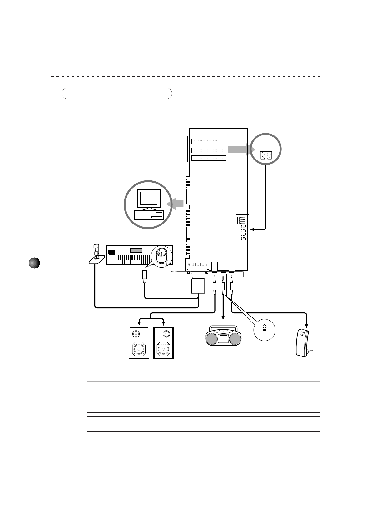
MAKING CONNECTIONS
The following diagram shows how to connect the various devices.
CD-ROM Drive
Audio Out
PC/AT Computer
Sound Edge
Sound Card
Joystick
External MIDI synthesizer, etc.
MIDI/JOYSTICK
OUTPUT
LINE IN
MIC
4
MIDI OUT
Dsub
-15 pin
Yamaha MIDI Adaptor Cable MDC-01
Audio Cable
Portable Cassette Recorder
or Stereo (for inputting
Power Speakers
external sounds)
¢Before making connections, be sure to UNPLUG THE POWER SUPPLY CORDS OF ALL DEVICES.
After making connections, switch on the power of each device in the following order: External MIDI devices first, then the
computer, then external audio devices. (NOTE: MAKE SURE TO TURN DOWN THE VOLUME LEVELS OF THE
EXTERNAL AUDIO DEVICES BEFORE TURNING THEM ON.) When turning off the power of each device, simply
reverse the process.
¢Improper connection of microphone and other external devices may cause ear injury or damage to
hardware.
Mini Jack
Stereo Mini Jack
Microphone
£There are various types of audio in and out jacks, so make sure to select the proper cables and adaptors
according to your respective devices.
£For information about jacks, see page 5.
Page 9
SOUND EDGE SETUP
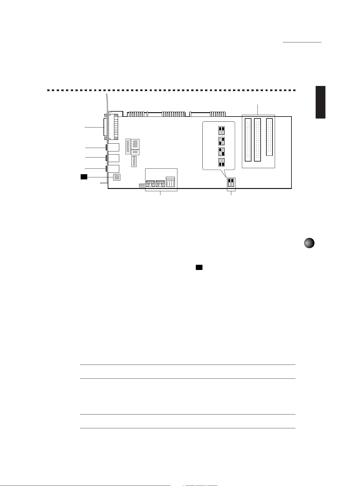
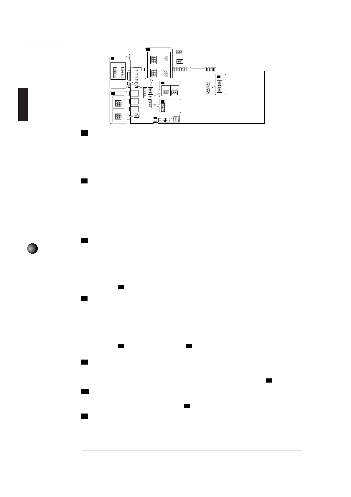
1. NAMES AND FUNCTIONS
SoundEdge Setup
6
4
1
2
3
J1
CN6 CN3
5
CN4
330
(Default)
320
310
300
2 1
OFF
ON
OFF
ON
OFF
ON
OFF
ON
CN5 CN1
CN2
7
1 OUTPUT jack: Stereo mini plug type jack outputs standard line-level stereo signals. Allows
connection to power speakers or the inputs of a recording mixer and other audio devices
including headphones.
2 LINE IN jack: Stereo mini plug type jack allows input of line-level stereo signals from
external audio devices.
3 MIC IN jack: Mono mini plug type jack allows connection to the included 2-lead condenser
type microphone (mono). MIC TYPE jumper J1(see next page) allows use of a 3-lead
condenser type or dynamic microphone.
4 MIDI/JOYSTICK connector: Dsub-15 pin type connector allows connection to a joystick
and/or external MIDI device using the optional Yamaha MIDI Adaptor Cable MDC-01.
5
5 CD IN connector: Allows stereo input of line-level signals from a CD-ROM. (Left, CN6:
Panasonic; Center, CN3: Mitsumi; Right, CN4: Sony.)
6 CD-ROM connector: Allows connection to a CD-ROM player. (CN5: Panasonic, 40-pin;
CN1: Mitsumi, 40-pin; CN2: Sony, 34-pin.)
* For connection and installation of a CD-ROM drive, see page 71.
* For CD-ROM drives other than Sony, Mitsumi or Panasonic, please use the proper interface
for connecting to your computer. (For details, see the owner’s manual which came with
your CD-ROM player.)
£When you use a joystick or CD-ROM drive, the Configuration setup should be done after connecting the
joystick/CD-ROM drive to the sound card. For more information about the Configuration setup, see page 66.
7 MIDI Port Address switch: Allows change of the MIDI Port Address for triggering the
internal AWM synthesizer sounds when playing DOS games. Four different types of MIDI
Port Addresses can be selected by combining SW1/2’s on/off status. (See pages 6, 16
and 67 for more information.)
¢You may need to change the MIDI Port Address (default address) if some conflict problem occurs. Please
consider which address to use before the sound card installation.
Page 10
SoundEdge Setup
J2
1
2
5
6
J3
12
5
5
4
4
3
3
2
2
1
1
1
Ground Pin
2
R Output Pin
L Output Pin
3
J1
1
314
2
3
314
2
MIC TYPE: Lets you switch back and forth between two types of amplifier configurations
J1
6
3
4
4
1
2
2
34
5
6
6
3
4
4
1
2
2
J4
1 2
12 12
J6
1
2
3
4
J5
21
: Indicates the Jumper is set to short (ON) position.
5
3
: Indicates the Jumper is set to open (OFF) position.
1
5
3
1
Ground Pin
L Input Pin
Ground Pin
R Input Pin
J7
3
5
7
9
10
11
depending on the type of microphone connected. (3-lead condenser or dynamic microphone;
2-lead condenser microphone.)
1 1-2 Short/3-4 Open: 2-lead condenser microphone (such as the one included with Sound Edge).
2 1-2 Open/3-4 Short: 3-lead condenser microphone or dynamic microphone.
* Default position is 1.
J2
OUTPUT TYPE: Lets you select whether to use the internal amplifier on the sound card or
not. Default is set to use the internal amplifier. When using an external amplified speaker,
do not use the internal amplifier. (In this case, use external audio devices having more than
10 kΩ input impedance.)
1 4-6 Short: Outputs the right channel without going through the internal amplifier.
2 3-5 Short: Outputs the left channel without going through the internal amplifier.
3 2-4 Short: Outputs the right channel via the internal amplifier.
4 1-3 Short: Outputs the left channel via the internal amplifier.
LEFT CHANNEL OUTPUT: Lets you select whether to output the left channel to the sound
J3
6
card’s OUTPUT jack or not. (The left channel signal is always output to the computer’s
internal speaker.) Normally, you should leave this as the default, to output the left channel
signal to the sound card’s OUTPUT jack.
1 3-4 Short: Outputs the left channel to the sound card’s OUTPUT jack.
2 3-4 Open: Outputs the left channel only to the computer’s internal speaker.
* If you wish to use only the computer’s internal speaker, select 2 as shown above and connect an appropriate
audio cable to
J4
RIGHT CHANNEL OUTPUT: Lets you select whether to output the right channel to the
.
J3
sound card’s OUTPUT jack or not. (The right channel signal is always output to the
computer’s internal speaker.) Normally, you should leave this as the default, to output the
right channel signal to the sound card’s OUTPUT jack.
1 1-2 Short: Outputs the right channel to the sound card’s OUTPUT jack.
2 1-2 Open: Outputs the right channel only to the computer’s internal speaker.
* If you wish to use only the computer’s internal speaker, select 2 as shown above and connect an appropriate
audio cable to
computer’s internal speaker.)
J5
PC-SPK (Computer speaker): Lets you input system (“beep”) sounds. The system
. (Connecting the audio cable to J3 will automatically designate the right channel output to the
J3
sounds come from the computer’s internal speaker via the sound card.
* To hear the system sounds from the computer’s internal speaker via the sound card, unplug one end of the
connector of the audio cable extended from the computer’s internal speaker and connect it to
INTERNAL LINE IN: Lets you input stereo line-level signals from an MPEG board. You
J6
J5
.
can apply effects to the input signals using application software such as EffectGear.
* Connect the MPEG board’s output connector to J6.
MIDI IRQ NUMBER: Lets you select the IRQ (Interrupt Request) number for triggering
J7
the internal AWM synthesizer sounds when playing DOS games. The default is set to 9.
(See pages 5, 16 and 67 for more information.)
¢You may need to change the MIDI IRQ number if some conflict problem occurs. Please consider which
number to use before the sound card installation.
Page 11

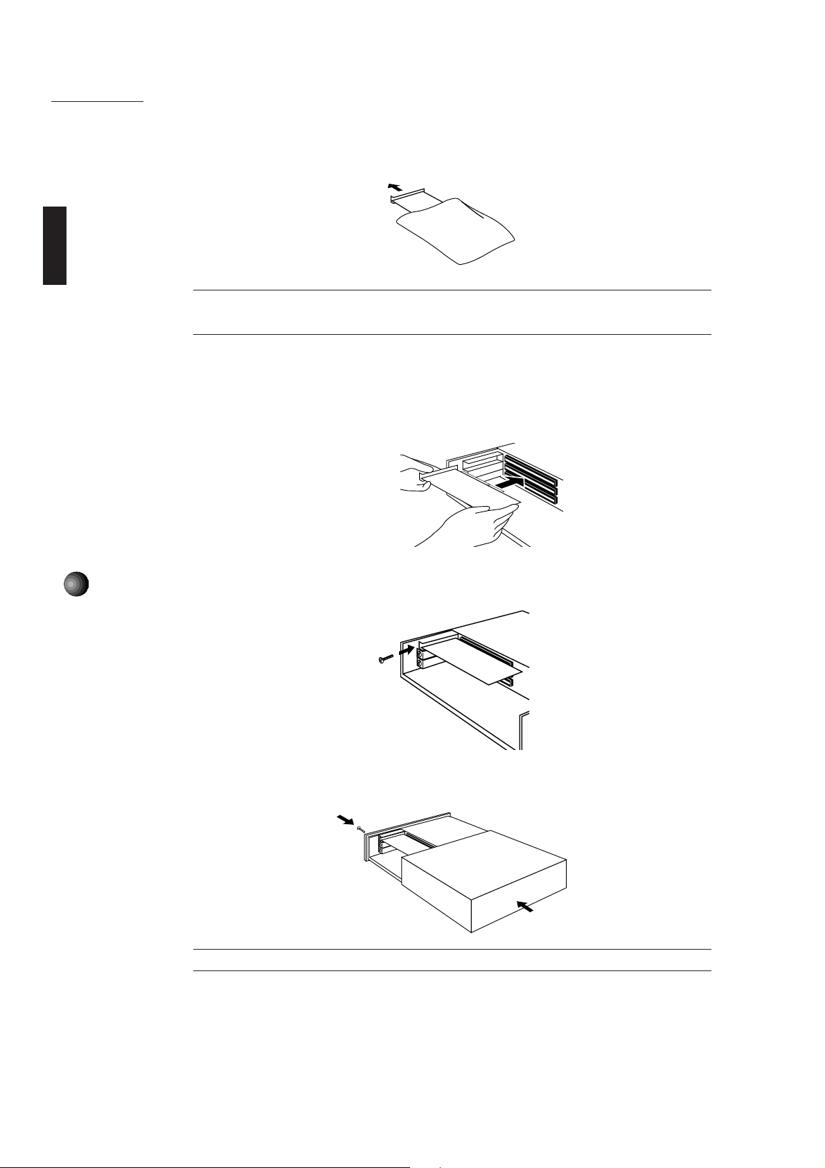
2. SOUND CARD INSTALLATION
The sound card fits into an expansion slot in your computer.
¢You cannot use more than one sound card. Please remove any other sound card which may already be
installed before attempting to install the Sound Edge.
1. Turn off the computer and unplug its AC power cord.
¢Do not attempt to install your sound card while the computer is plugged in. This can cause irreparable
damage to the sound card, and may pose a serious shock hazard!
2. Remove the top cover of the computer.
SoundEdge Setup
£The proper method for removing the top cover varies depending on the type of computer you use, so please
see your computer's owner's manual for the proper procedure. Wear gloves to avoid cuts by any sharp edges on the
cover.
3. To remove the expansion slot cover, simply unscrew it and take it away.
£Be sure to keep the expansion slot cover in a safe place for future use.
7
Page 12
SoundEdge Setup
4. Carefully remove the sound card from the anti-static bag.
¢Before touching the sound card, first touch a metal surface to discharge any static electricity in your body;
such static electricity can cause serious damage to your Sound Edge. Also do not touch the inside surfaces of your
sound card in order to prevent possible interference with or damage to the circuitry.
5. Hold the sound card with two hands as shown, and slowly and steadily insert it into the
expansion slot, making sure to properly line up the connectors in the card with those in the
slot. To prevent breaking or damaging the sound card during installation, do not use
excessive force when inserting the sound card into the expansion slot.
8
6. Use the screw from step 3, above, to secure the sound card to the computer.
7. Finally, carefully replace the top cover of your computer.
£To remove the sound card, simply reverse the above process.
Page 13
3. SOFTWARE INSTALLATION
Installing the Software
The four floppy disks included in the Sound Edge package—Install Disk 1, 2, 3, 4—contain
both Yamaha and Voyetra application software programs.
¢To ensure proper installation, before installing the software, be sure to exit all applications which may be
active (including Windows) and reboot the MS-DOS.
¢If you removed a previous sound card before installing the Sound Edge, be sure to delete its accompanying
driver programs.
¢When you install the Yamaha Sound Edge application software, the MIDI Mapper will be overwritten.
The installation program also overwrites the AUTOEXEC.BAT, SYSTEM.INI, CONTROL.INI and CONFIG.SYS files. If
you don’t want to lose any existing data, please save them before you install the Sound Edge application software.
Installation Procedure
■ Installing for DOS
SoundEdge Setup
1. Insert Install Disk 1 into your floppy disk drive.
2. Select the floppy disk drive where the Install Disk 1 is inserted.
£This manual assumes that your floppy disk drive is the A drive. If your drive is different, then choose the
drive specified for your computer.
3. Type A:INSTALL, then press the <ENTER> key.
A:INSTALL + <ENTER>
£You cannot perform installation from the MS-DOS prompt in the Windows Main group, so be sure to shut
down Windows before installing the software.
9
Page 14

SoundEdge Setup
When Install Disk 1 is verified, the following screen will appear.
£If you want to quit the installation process, press the <ESC> key.
4. Press any key on your computer keyboard.
The Installer screen is replaced by the Name screen.
10
Select the drive onto which you want to install the Sound Edge software.
£The default setting installs the software to a C drive.
If you want to use a different drive, type in the name of the different drive. If you intend to use SampleEdit, see page
61, leave the drive name and directory name as their defaults (drive C, \yamaha directory.)
5. Verify the drive name and press the <ENTER> key.
The Installer screen is replaced by the Directory Name screen.
Type the name of the directory into which you want to install the software (or use the
default name).
£The default name is yamaha. You can change the name by typing in a new name. If you intend to use
SampleEdit, leave the drive name as the default.
Page 15

6. Verify the directory name and press the <ENTER> key.
The Directory Name screen is replaced by the following screen.
7. Verify the drive and directory name—if correct press <Y>; if incorrect press <N>.
Pressing <N> will return you to the beginning of the installation procedure.
Pressing <Y> will start copying the files for installation. After a few moments, a screen
appears asking if you wish to change AUTOEXEC.BAT file.
SoundEdge Setup
8. Press <Y> on your keyboard.
The original AUTOEXEC.BAT file will be saved under a different name and the following
screen appears.
9. Press any key on your keyboard to continue.
The following screen appears.
11
Page 16

SoundEdge Setup
10. Press either <Y> or <N> on your keyboard.
For Windows users, press <Y> to proceed to
(For DOS users, press <N> to finish the installation.)
This completes the software installation for DOS.
Installing for Windows
, below.
12
£If you only wish to use these programs on the DOS, proceed to
£You can also use the sound card on your DOS program for game applications.
M16INIT Setup Procedure
, page 66.
■ Installing for Windows
If you pressed <Y> in step 10, above, the screen will be replaced by the window shown below.
This is where you begin the software installation for Windows.
£ If the Windows installation does not begin, you will need to set up the proper M16INIT configuration
according to your computer's specification. See page 66 for details.
11. Click [OK].
£To stop the installation process, click [Cancel].
The following window appears and installation begins.
The above window will show the progress of the installation for Windows on a graph. Then
the following window appears.
12. Change the disk in the floppy disk drive to Install Disk 2 and click [OK] to continue copying.
Page 17

SoundEdge Setup
13. Follow the instructions which appear in the dialog boxes to copy all disks, one after another.
When the installation is completed, the Yamaha Sound Edge group and the Voyetra group
will be registered in the Program Manager of your Windows system.
14. Finally the following screen will appear.
Press <Y> to restart your computer.
AUTOEXEC.BAT
The Sound Edge software program will automatically add the following lines to the
AUTOEXEC.BAT file.
rem -- Sound Edge installer wrote. Do not modify here -echo off
set OPL4DRV=-I9
set MAD16=C:\yamaha\mad16
set BLASTER=A220 I5 D1 T4
C:\yamaha\mad16\m16init /B
C:\yamaha\kpcon /wait:1000 /type:2 /t2aor:2048 /t2aol:2048 /t2dpt:256 /t2mic:512
call C:\yamaha\ymhini.bat C:\yamaha
rem --
13
SYSTEM.INI
The Sound Edge software program will automatically add the following lines to the
SYSTEM.INI file.
[386Enh]
device=vmad16.386
device=vm16midi.386
[boot]
drivers=mmsystem.dll msmixmgr.dll
[drivers]
midi1=m16midi.drv
wave=mad16c.drv
aux=mad16c.drv
midi2=opldld.drv
mixer=mad16c.drv
[m16midi.drv]
Interrupt=5
Installed=1
[MAD16C.DRV]
DMADAC=0
DMAADC=0
Interrupt=11
IOAddress=530
SingleModeDMA=No
DMABufferSize=32
[OPL4 Driver]
ROM=-1
FM=0
RAM=0
PCM_BOOST=0
AUTO_RESET=0
FAST_DAMP=0
PCM_MIX=0
FM_MIX=0
CONTROL.INI
The Sound Edge software program will automatically add the following lines to the
CONTROL.INI file.
[drivers.desc]
m16midi.drv=Opti External MIDI Driver
mad16c.drv=YAMAHA Audio Device Driver
opldld.drv=YAMAHA OPL4 Driver
[Userinstallable.drivers]
midi1=m16midi.drv
wave=mad16c.drv
midi2=opldld.drv
Page 18

SoundEdge Setup
ABOUT THE DRIVER AND MIDI MAPPER
In order for Windows to work with MIDI, a driver and MIDI mapper are required. The Yamaha
Sound Edge software installation procedure automatically places the YAMAHA OPL4 Driver in
the Control Panel and the YAMAHA OPL4 MIDI map into the MIDI Mapper.
When you click to open the driver in the Windows Main group, you can see three different
drivers: OPTi External MIDI Driver, YAMAHA Audio Device Driver and YAMAHA OPL4 Driver.
¢If you removed a previous sound card before installing the Sound Edge, delete any accompanying driver
programs.
Setting Up the YAMAHA OPL4 Driver
This driver lets you assign instrument voices from the ROM (AWM wave table), FM tone
generator or RAM (sampled sounds) to each of the 16 MIDI channels.
1. Double click the [Control Panel] icon in the Main group. The following window appears.
14
2. Double click the [YAMAHA OPL4 Driver] icon. The OPL4 Drive Panel dialog box appears.
bar up and down to change
Type of Tone Generation
ROM: GM compatible AWM
wave table.
FM: 128 musical instrument
voices using high quality 2operator FM tone
generation.
RAM: WAV files which can
be played on a musical
scale. (See SampleEdit on
pages 47 and 57.)
Ch.: Check the appropriate
box beside each MIDI
channel number to select
the type of tone generation
you want.
ALL ON/OFF: Click one of
these once to select an
entire column of the desired
type of tone generation.
Balance: Move the scroll
the volume balance between
the PCM (ROM/RAM) and
FM sounds.
Wave Boost: Click this box
to automatically boost the
melody part by 8dB and the
rhythm part by 10dB.
Auto Reset: Click this box to
reset MIDI data
transmission/reception every
time software playback stops
or pauses.
Fast Damp: Click this box to
cut off the last portion of
notes in order to prevent
notes from interfering with
proper note on of
subsequent notes. Note on/
off data transmission and
reception may sometimes be
disrupted when using a
computer with a slow CPU.
£In the default setting all MIDI channels are assigned to “ROM” (the AWM wave table).
3. After choosing your settings, click [OK]. Click [Cancel] to cancel the settings.
Page 19

Setting Up MIDI Mapper
MIDI Mapper lets you select either the internal MIDI sound card (OPL4) or an external MIDI
device in order to play MIDI data.
1. Double click the [MIDI Mapper] icon in the Control Panel window.
The MIDI Mapper window appears.
2. Select [Setups], and click the [ ] button in the dialog box. A list appears.
SoundEdge Setup
3. Select the proper map according to your setup.
Select [YAMAHA OPL4] to play the internal tone generator (OPL4).
Select [YAMAHA Ex-MIDI] to play an external MIDI tone generator.
£The internal tone generator (OPL4) is selected as the default setting.
¢When you install the Yamaha Sound Edge application software, the MIDI Mapper will be overwritten.
If you don’t want to lose existing data, please save it before you install the Sound Edge application software.
15
Page 20

SoundEdge Setup
About the MIDI Interface for DOS
The Sound Edge MIDI Interface lets you use the internal AWM synthesizer to play the
sounds of GM compatible DOS games and sequencers.
When the Sound Edge software installation is done properly, the following lines will automatically be
added to CONFIG.SYS and AUTOEXEC.BAT:
To CONFIG.SYS: DEVICE=C:\YAMAHA\OPL4TSR.SYS (Device Driver on the DOS system)
To AUTOEXEC.BAT: SET_OPL4DRV=-I9 (Command option which assigns the IRQ number 9
to the Environment Variables)
* The symbol “_” indicates a space in a command.
£If the DOS games cannot run because of a memory shortage of the conventional memory in your computer,
relocate the Device Driver to the UMB/HMA(Upper Memory Block/High Memory Area) area. Change the line in the
CONFIG.SYS to the following and restart your computer.
DEVICEHIGH=C:\YAMAHA\OPL4TSR.SYS
Executing OPL4DRV.COM
1. Set the MIDI Port address of the DOS game to match the MIDI Port address of the sound card
DOS MIDI interface. The default is 330.
Also select [General MIDI] from the sound setup window of the DOS game.
16
£See page 67 for more information on the MIDI Port and IRQ.
£Depending on the external devices you use, the games may not run because of a conflict caused by
the MIDI Port and IRQ settings. If this happens, you must change the MIDI Port address and IRQ number to
the currently available address and number. See pages 5 and 6 for how to change the address and number.
Do not use the same IRQ number as the default for the sound card SB mode, IRQ number 5.
2. Start up the execute program by typing the following command on the DOS command line.
[KEY OPERATION]
CD\YAMAHA + <ENTER>
OPL4DRV + <ENTER>
The following display appears.
The above procedure enables you to use the internal AWM synthesizer to play the sounds of GM
compatible DOS games and sequencers. The execute program remains effective until you turn
the power off.
£If you want to cancel the program, type the following line: OPL4DRV2 -R.
Turning the power off also cancels the program.
£If you intend to load the execute program in the UMB/HMA area and start up the execute program,
type the following command:
[KEY OPERATION]
CD_\YAMAHA + <ENTER>
LH_OPL4DRV + <ENTER>
Page 21

Sound Edge Application Software
SOUND EDGE APPLICATION SOFTWARE
Sound Edge application programs can be used with Windows or DOS. Running the Sound Edge with
Windows allows you to take full advantage of the complete multimedia capabilities of the software
and hardware.
DSP
Hello...
?
EffectGear
Applies various effects to the
input signal and synthesizer
sounds, and acts as a mixer.
Applies interesting effects to
the input signal and
synthesizer sounds.
For use with Windows
VoiceMorph
EffectEdit
Let’s you create your own effects.
KPLOAD
Let’s you add various effects
through DOS commands.
For use with DOS
SampleEdit
Let’s you play WAV files
on a musical scale.
DSP
t[x]dpt:[y]
KPCON
Let’s you control the
effects through DOS commands.
17
Page 22

Sound Edge Application Software
WINDOWS APPLICATIONS
The Yamaha Sound Edge has an on-board DSP (effects processor) that can perform various types of effects
on AWM wave table sounds, CD-ROM audio playback, and signals input by a microphone. In Windows the
Yamaha applications EffectGear, VoiceMorph and EffectEdit are used to control the function of the DSP
chip. In addition to the effect related applications, SampleEdit enables waveform editing of sound files and
lets you trigger the multiple wave data on a musical scale with a sequencer. This section explains how to use
these four applications.
¢Please note that EffectGear, VoiceMorph and EffectEdit cannot be used all at the same time, since each
individual effect is created by the single DSP. If you accidentally activate another Sound Edge application at the same
time, the following warning dialog box appears.
The Mixer of the Voyetra AudioStation will also perform the same way, using the single DSP, so you will not be able to
start it for the same reason. Regarding use of the Voyetra applications, see the
£If you pull the Volume faders down on the Mixer module of the AudioStation, the volume of Sound Edge
applications will also be attenuated.
Voyetra User’s Guide
for details.
18
EffectGear
Along with the mixer functions EffectGear lets you apply various types of effects to the signal input by a
microphone, the line-level input signal from CD-ROM audio playback, and to the AWM wave table and FM
sounds. The mixer functions for each input (such as microphone and CD audio) let you adjust the relative
volume levels to enjoy karaoke sing-along sessions.
Startup Procedure
Double click on the [EffectGear] icon and the EffectGear application will start.
Page 23

Names and Functions
Sound Edge Application Software
3
1
2
9
8
4
5
6
7
1 ABOUT button:
Click this button to see information about this version of EffectGear.
2 PULL DOWN MENU button:
Click this button to open the list of effect types. You can also open the list of effect types by
double clicking on the [Effect] display box.
3 EFFECT display box:
The name of the currently selected effect type will appear in the display box.
4 POWER OFF button:
Click this button to exit EffectGear.
5 MINIMIZE button:
Click this button to resize the EffectGear window to icon size.
6 VOICE CANCEL button:
Click this button to reduce the volume level of the vocal from a song from CD audio playback
for karaoke sing-along accompaniment.
19
7 HELP button:
Click this button to call up EffectGear Online Help, which will appear at the bottom of the
EffectGear window.
8 PITCH SHIFT buttons:
Click these buttons repeatedly to increase or decrease the pitch of sound by a semitone
(100 cents), which will be displayed on the LED. Original sound pitch is represented by
center position = 0; each click will move the LED display ±100 cents at a time, to a maximum
and minimum of ±400 cents.
9 SLIDERS:
The function of each slider is represented by an icon located to the left of it. Moving the slider
toward the right will increase the value of each function.
SYNTHESIZER: Lets you adjust the volume of the Sound Card’s synthesizer (AWM
wave table and FM tone generator).
MICROPHONE: Lets you adjust the microphone input level.
LINE: Lets you adjust the line input level.
EFFECT FEEDBACK: Lets you adjust the effect feedback level.
EFFECT DEPTH: Lets you adjust the range of the effect depth.
MASTER VOLUME: Lets you adjust the overall output volume level.
£There are similar functions in the Mixer module of the Voyetra AudioStation; however, the pitch shift ranges are not
equivalent.
£Depending on the type of effect you select, Voice Cancel and Pitch Shift may not be applicable, and the button
display will gray out.
Page 24

Sound Edge Application Software
Operation
1. To display the effect type list, click the [Pull Down Menu] button or double click on the
[Effect] display box.
2. Select an effect type from the list which appears.
£There are 32 different types of DSP effects to choose from, including everything from “Hall” and “Room” reverbs to
unique “Alien Voice”, “Devil” and others. These provide an interesting extra dimension to karaoke sing-along or for
game sounds. These are placed in the \YAMAHA\DATA directory (extension .KPE) and you can create your own new
files using EffectEdit to edit them. (See page 23.)
3. To adjust volume balance and level (or range) of an effect, move the sliders right or left. Try
listening to the input signals from a microphone or CD while adjusting the effect level by
moving the slider from right to left.
20
Page 25

Sound Edge Application Software
VoiceMorph
VoiceMorph lets you apply unique effects to line-level and microphone signals that completely alter the original
sound. You can also apply VoiceMorph effects to AWM wave table or FM instrument sounds when playing
back a MIDI song file with the sequencer program.
Startup Procedure
Double click on the [VoiceMorph] icon and the VoiceMorph application will start.
Names and Functions
1
2
1 Menu Bar/Pull Down Menus:
■ Source
Lets you select the sound source.
21
Mic:
Lets you select microphone input. (This is the default setting.)
Line In/Synth:
Lets you select the input source, either [Line In] (CD or other external sound source) or
[Synth] (AWM wave table or FM tone generator).
Page 26

Sound Edge Application Software
■ Control
Gain/LFO Setup:
Lets you open the Control Panel to set up the output (“Gain”) level or the LFO settings.
■ Help
Contents:
Lets you open the Online Help.
About VoiceMorph:
Lets you see information about this version of VoiceMorph.
2 Type:
There are 16 different types of voice change programs which will appear in the window.
Selecting [Thru] will let the original sound signal pass through without applying a VoiceMorph
effect.
22
Operation
1. First select the desired source ([Mic] or [Line/Synth]) from the [Source] menu.
2. Click on the effect type icon that you want.
3. Use a microphone or CD (or other audio device) to input sound to be effected.
Setting Output Level and LFO Settings
You can adjust the output gain level or LFO settings for various effects.
1. Select [Gain/LFO Setup] from the [Control] menu. The Control Panel window appears.
Output Gain: Lets you adjust the
output gain level by moving the slider
to the left (Min) and right (Max).
LFO (Low Frequency Oscillator):
Lets you control the depth and speed
of the LFO. The LFO changes sound
pitch, tone or volume in a cycle
determined by depth and speed
values.
• Depth
Adjust LFO depth by moving the
slider to the left (Min) and right
(Max).
• Speed
Adjust LFO speed by moving the
slider to the left (Slow) and right
(Fast).
LFO is applicable to the
following effect types: Vibrato,
Stereo Vibrato, Saw, Stereo Saw,
Random, Stereo Random and
Fast Pan effects.
2. Adjust the Gain/LFO settings for the output level and the LFO.
3. When you’ve finished, click [OK]. The Control Panel window closes and the previous
window appears.
Page 27

Sound Edge Application Software
EffectEdit
Compared to EffectGear and VoiceMorph, EffectEdit gives you more control over the internal DSP, since it can
be used to edit and reconfigure the DSP.
The Sound Edge DSP has four different types of effects programs and provides three different kinds of sound
input—from the AWM wave table and the FM tone generator, from the stereo analog input, and from the mono
input (through a Microphone), and analog stereo output.
EffectEdit lets you fine tune delay time or transpose the pitch of the input sound. You can save your original
effects created with EffectEdit and use them with EffectGear and KPLOAD (DOS).
About DSP Delay, Echo and Surround Effects
Surround Effect
DSP
LEFT
Original
Delay Effect Delay Effect
Reflection Reflection
The DSP digital effect processor processes sound signals electronically to change the pitch
or create artificial ambience—or simulated rooms and other sound environments. A high
quality “delay” unit is at the heart of the DSP, which simulates ambience by delaying the
original sound and creating layers of delayed sounds to mix with the original sound.
The karaoke “echo” sound simulates the delay effect caused by the way sound reflects off
walls in a room. You can create a multi-directional “surround” effect by assigning independent
delays to both the left and right signals.
Sound
RIGHT
Indicates reflection of sounds.
23
¢Starting EffectEdit will automatically cancel the present effect setup and some noise may occur. Therefore, please turn
down the master volume in the Mixer window of EffectGear before you start EffectEdit.
Page 28

Sound Edge Application Software
Startup Procedure
Names and Functions
Pull Down Menus
Double click on the [EffectEdit] icon and the EffectEdit application will start.
The EffectEdit window has a pull down menu and block diagram which is configured with various
controllers.
■ File
24
New:
Lets you open a new DSP block diagram by choosing from Type0~3 to edit the effect program
from scratch.
Open:
Lets you open an existing block diagram file; a dialog box will appear for file selection.
Save:
Lets you save the current file, overwriting the existing version; the file extension is .KPE.
Input Caption
When you first save a newly edited file, the Input Caption dialog box will appear before the
Save As dialog box appears. The name you type in here will become the title of your
EffectGear file (file extension .MBJ), and will also appear on the title bar of EffectEdit.
Save As (Name file and save):
Lets you name and save an edited block diagram file. The Save As dialog box will appear.
Make MBJ File (Convert file to .MBJ and save):
Lets you convert an edited block diagram file to an EffectGear format file and save it. (To use
the file with EffectGear, you must save the edited block diagram file as a .MBJ file within the
\YAMAHA\DATA directory.)
Exit:
Lets you exit the EffectEdit program.
Page 29

Sound Edge Application Software
■ Memory
Lets you determine the signal processing memory allocation for each controller of the DSP
in the block diagram, including Mic Echo, Key Control and Surround 1 and 2.
Key Control’s DSP memory allocation and Type1’s DSP memory layout allocation are fixed.
When you select [Memory] the Memory Layout setup dialog box appears.
Move the [Balance] slider right or left to adjust the memory allocation. Assign more memory
to Surround to achieve a deeper, longer delay.
■ About
Displays information about this version of EffectEdit.
25
Page 30

Sound Edge Application Software
Block Diagram
When you start EffectEdit the Type0 window appears.
The block diagram let’s you edit effects graphically. In this block diagram, the sound signal is
input through the mixer from the left side, passes through the controllers such as Mic Echo and
Key Control, then goes through a mixer before being output on the right side.
There are four types of effect programs (each represented by a specific block diagram). The
number and kind of controller varies depending on which type you choose.
Click and open each controller setup dialog box to configure the input signal as you like.
26
Four Types of Effect Programs
Type0:
Sound enters via the Audio/MIDI input, goes through Voice Cancel, then through independent
L (left) / R (right) Key Control pitch shifters, then through the Surround delay.
Voice Cancel reduces the level of the vocal part of a song which is input at the CD IN
connector for karaoke sing-along. You can also shift the pitch (by Key Control) of the entire
sound or apply an echo effect (by Mic Echo) to the MIC input signal.
Page 31

Sound Edge Application Software
Type1:
The Audio/MIDI input goes through Voice Cancel and the MIC IN input goes through the
Key Control pitch shifter, then passes through the Surround delay. Since Key Control is
connected to MIC IN, you can use it to produce special sound effects like those in
VoiceMorph, as well as chorus effects.
Type2:
The Audio/MIDI input goes through Voice Cancel then through two independent Surround
delays. Since Type2 does not include Key Control, you can apply more precise Surround
effects than with Type0 and Type1.
Type3:
All available memory in the DSP is assigned to the two Surround delay effects in order to
produce higher quality surround effects or deeper echoes than possible by Type2.
27
Page 32

Sound Edge Application Software
Controller and Mixer Setup
There are basically six types of controllers and mixers. Click on either a [controller] or [mixer]
box to open the setup dialog box.
Effect Program Overview (Type0)
?
28
INPUT MIXER
VOICE CANCEL
KEY CONTROL
MIC ECHO
SURROUND
OUTPUT MIXER
INPUT MIXER
To select the input signal and control the input levels of selected input signals.
VOICE CANCEL
To eliminate frequencies around the vocal of the external input signal, such as a CD, in
order to produce a karaoke accompaniment for sing-along using a microphone.
MIC ECHO
To apply an echo effect to the MIC IN or LINE IN (mono) signal, such as to your own voice.
KEY CONTROL
To shift the pitch, or transpose the key of the input signal. Key Control also lets you apply a
delay effect (Type1 only). You can adjust the key to match your voice range, and create
harmonies (harmonizer effect) by using two independent Key Controls, one set to a higher
pitch and the other set to a lower pitch.
INPUT
SURROUND
To set up a precision delay. Type2 and Type3 have two Surround effects. You can create
various ambient environments by applying Surround effects to your own singing voice and
karaoke accompaniment.
OUTPUT MIXER
To control the overall levels of the original (“dry”) sound and delayed (“wet”) sounds.
Page 33

Sound Edge Application Software
Mixers
There are three types of mixers: one for input, one for output, and one for remix.
■ Input Mixer
The Input Mixer is located on the left side of the dialog box. The input channels are configured
by MIDI L/R, Audio L/R, Audio L as mono and Mic inputs. Each has two lines.
Click on the desired [Input Mixer] to display the Input Mixer setup dialog box.
4
1
2
3
1 Sign:
Lets you control the “phase”, where [+] represents positive phase and [-] represents negative
phase. “N” will cancel the input without having any relation to fader level.
2 Level Fader:
Lets you control input level by moving a level fader.
3 Value:
Displays a numeric level value.
4 Control Menu Box:
Acts the same as that in Windows. Double click the [Control Menu] box to close the Input
Mixer setup dialog box when you are finished making settings.
£Every Control Menu box acts the same way as in the controller setup dialog boxes, described above; therefore,
such explanations will be eliminated hereinafter.
About the Types of Input Channels
You should select the appropriate input channel according to your needs. Be sure to raise
the fader to an appropriate level in order to achieve the desired effect; otherwise the settings
you make will have no effect.
MIDI L/R Channel:
For input from the internal AWM wave table output and input from the internal FM output.
29
Audio L/R Channel:
For input from the internal digital audio or external LINE/CD signal (stereo).
Audio L Channel:
For input from the internal digital audio or external LINE/CD input (mono).
Mic Channel:
For input from an external microphone.
Page 34

Sound Edge Application Software
■ Output Mixer
The Output Mixer is located on the right side of the block diagram. The analog L/R output signal
will be output from two separate mixers.
Click the [Output Mixer] box to open the Output Mixer setup dialog box.
30
1
1
3
3
2
2
1 Sign/Level/Value:
Same as for the Input Mixer; however, in this case for signal output.
2 Thru:
To adjust the output level of the original (“dry”) sound.
3 Surround:
To adjust the output level of the delayed (“wet”) sound.
Type1 includes two mixers which remix the sound from the two Key Controls, located in
the center of the block diagram.
Voice Cancel
You can set Voice Cancel to either cancel the vocal part or pass the signal through unaffected.
Type3 does not have the Voice Cancel function.
Click the [Voice Cancel] box to display the Voice Cancel setup dialog box.
1
2
1 Thru:
Passes the original input signal without applying Voice Cancel.
2 Voice Cancel:
Reduces the sounds at the center of the frequency range, or the vocal part of the song
being input, since in most cases this is where the vocal part is located. Use Voice Cancel for
karaoke sing-along to the music without the original vocal part.
Page 35

Sound Edge Application Software
Mic Echo
Mic Echo is available in Type0. You can use Mic Echo to delay the input signal or filter the input
signal to modify frequency characteristics.
Click the [Mic Echo] box to open the Mic Echo setup dialog box.
1
2
1-1
2-2
1 IIR Filter (Infinite Impulse Response Filter)
The IIR filter is a cyclic type filter that eliminates a certain frequency range from the original
sound signal.
1-1 fc (frequency cutoff)
To determine the point of frequency cutoff in hertz (“Hz”). Click [a]/[z] to modify the
value 100 Hz at a time with each click, or highlight the [fc] box and type in a new value.
1-2 type:
Click the [type] button to select the type of filter you want.
Thru:
Passes the original sound through the IIR Filter unaltered.
31
H.P.F (High Pass Filter)
Lets the high frequencies pass and cuts off the low frequencies as shown
below.
Level
Low Frequencies
Cutoff Point
High Frequencies
Frequency
L.P.F (Low Pass Filter)
Lets the low frequencies pass and cuts off the high frequencies as shown
below.
Level
Low Frequencies
Cutoff Point
High Frequencies
Frequency
Page 36

Sound Edge Application Software
Key Control
2 Delay Design Box
Delay is like a simultaneous echo effect. You can set the time, volume, and number of
delays.
Sign +
Volume
Sign−
Time
On the right side in the Delay Design box you can set the delay by clicking and dragging the
[red point] up and down to determine the time and volume of delay feedback. As you click
and drag the [red point] to the right, the time location (unit = ms [millisecond]) will appear on
the upper right side of the Mic Echo setup box, along with a black point. After clicking and
dragging the [red point] to the right, also click and drag the [black points] to determine the
number of delays and their time and volume settings.
32
Key Control is available in Type0 and Type1. You can use the Key Control filter to modify the
input signal frequency characteristics, or transpose the input signal, as well as apply delay or
adjust the delayed sound and transposed sound with Type1.
Click on the [Key Control] box and the Key Control setup dialog box appears. (The L/R channel
setups will be displayed on the same dialog box.)
2
Type0
1
3
1
2
1 IIR Filter (Type0):
See
Mic Echo
, above, for information about the IIR filter.
Type1
1
2
3
1
245
4
2 Key Shift (Type0):
To transpose the input signal within ± two octaves. Units are cents. Click [a]/[z] repeatedly
to adjust the key up or down 100 cents (a semitone) at a time, or highlight the [pitch] value
box and type in the desired value.
5
3 Delay Design Box (Type1):
To set the time, volume, and number of delays.
4 Delay (Type 1)
To adjust the output level of the delayed sound.
5 Key Shift (Type1):
To adjust the output level of the transposed sound.
Page 37

Sound Edge Application Software
Surround
With Surround you can apply precise delay effects to the input signal.
Click the [Surround] box and the Surround setup dialog box appears.
3
1
3
2
1 Input:
Same as Sign/Level/Value in the Input Mixer, above; however, in this case it adjusts the
signal level input to the Surround.
2 IIR Filter:
See
Mic Echo
, above, for information about the IIR Filter.
3 Delay Design Box:
Delay is like a simultaneous echo effect. You can set the time, volume and number of delays.
Mic Echo
See
£
•“Reverse” from the Surround box indicates signal sound loop. •
Output which feeds back into input indicates signal sound loop for each setup window.
• Surround 2 in Type2 and Type3 has an input channel exclusive to the signal sound loop as well as other inputs.
• The number of delays in the Delay Design Box may vary depending on the controller.
• Depending on the Memory setup (see page 25), you cannot set up the delay feature (e.g., if you allocate too much
memory to others, such as Mic Echo).
, above, for information about the Delay Design Box.
33
Page 38

Sound Edge Application Software
Operation
This section describes basic operations and provides a tutorial showing how to create an effect
program.
We’ll make an effect by using a microphone input sound split into two voices, one an octave
higher (right channel) and one an octave lower (left channel) than the other, and adding an echo
type effect to them. This effect is similar to some effects in VoiceMorph.
First connect a microphone to the MIC jack of the Sound Edge sound card.
1. Select [New] from the [File] menu on the menu bar.
The Type Select dialog box appears.
Select [Type1], then click [OK]. The Type1 block diagram will apply Key Control to the
microphone input sound.
34
1
Transpose
To make the voices one octave higher and one octave lower from the original voice, you’ll
need to modify the Pitch (pitch of the input voice) using Key Shift in the Key Control dialog
box. First you’ll need to raise the microphone input level of the 4th and 5th (from the top)
Mixers.
2. Click the 4th (from the top) [Input Mixer]. The Input Mixer setup dialog box appears.
Page 39

Sound Edge Application Software
3. Click and drag the [Mic input level] fader upward and set it to a value of about 80. Double click
the [Control Menu] box in the upper left corner to close the Mixer box.
4. Click the 5th (from the top) Input Mixer box to open the Input Mixer setup dialog box, then
click and drag the [Mic input level] fader also up to 80. Double click the [Control Menu] box in
the upper left corner to close the Mixer box.
5. Click the [Key Control] box. The Key Control setup dialog box appears.
1
2
6. On the right side of the Key Control setup dialog box, click and drag the [output level] fader for
both upper and lower KeyShift to maximum.
7. Modify the pitch one octave higher in the upper 1 Key Shift by clicking [▲] to 1200.
Listen to your voice to verify the value while modifying the pitch.
8. Modify the pitch one octave lower in the lower 2 Key Shift by clicking [▼] to -1200.
Double click the [Control Menu] box to close Key Control.
£You should be able to hear the right channel sound one octave higher and the left channel sound one octave
lower than their normal settings.
35
Page 40

Sound Edge Application Software
Apply Echo
Now let’s apply an echo effect. You’ll need to increase the Surround output level on the right
Output Mixer to audition the amount of echo while modifying the setting.
9. Click the [Output Mixer] box to open the Output Mixer setup dialog box, then click and drag
the [Surround] fader to increase the Surround output level to maximum position. There are
two Output Mixers. Set both to the same value.
36
Double click the [Control Menu] box in the upper left corner to close the Output Mixer.
10. Click the [Surround] box. The Surround setup dialog box appears.
(Red)
(Red)
11. On the left side of the setup dialog box, increase the input level by clicking and dragging
both [L/R] level faders to maximum positions.
12. Drag the [red point] on the left side of the upper (R) Delay Design box to the position on
the right as shown in the above illustration.
£The red colored graph indicates feedback delay time and volume. Time location (unit = ms [millisecond]) will
be displayed on the upper right side of the Delay Design box as you drag. Also, the red point in the lower (L) delay
design box will automatically move according to the delay time that you previously designated, above.
£By listening to your voice while you make settings, you can better judge the amount of echo applied.
£After moving a red point, a black point will appear in the red point’s original position.
Page 41

Sound Edge Application Software
13. Drag the [black point] to the right as shown in the illustration on the previous page.
When you move the black point to a new location in the upper (R), the time location of the
black point in the lower (L) will adjust accordingly. There are seven black points in total.
Double click the [Control Menu] box in the upper left corner to close the Surround setup
dialog box.
Saving the Effect Program
After modifying setups you will need to save the effect program (.KPE). You may create a
.MBJ file so that you can use your new effect program with EffectGear.
14. Select [Save] from the [File] menu.
The Input Caption dialog box appears (if your edited effect file is new).
15. Type in the caption name, then click [OK].
(This caption will become the file title in the EffectGear’s effect type list.) After the Input
Caption box closes, the Save As dialog box appears.
16. Type the drive name, directory and file name where you want to save your new effect file.
You can use any file name, but type .KPE at the end of the file name.
17. If you wish to use this newly edited file with EffectGear, select [Make MBJ file] from the
[File] menu and the Save As dialog box appears.
18. Make sure the \YAMAHA\DATA directory is selected, then save the file, using .MBJ as the
file extension.
£Save .MBJ files in the \YAMAHA\DATA directory. If a .MBJ file is in another directory, you cannot use it with
EffectGear.
EffectEdit has powerful sound sculpting capabilities. The graphic DSP editing features let you
easily make precise adjustments to the sound. Select another type of effect and try creating
your own original effect program.
EffectEdit Sample File
In addition to the preset .KPE files for EffectGear, the \YAMAHA\DATA directory includes
.KPE sample files as additional examples to help you understand the function of the
controllers, which will give you practical information before actually using EffectEdit. You
can easily make your own original files by editing a sample file that’s close to the effect
that you want to create.
Sample File List
File name Effect type Contents
KARAOKE.KPE 0 For karaoke effect, echo effect for microphone
input signal, VoiceCancel and Pitch Shift for CD
input signal.
HARM-MJ.KPE 1 For three-voice harmony effect. Delay effect
creates expanding ambiance.
DELAY.KPE 2 Creates typical delay effect.
REVERB.KPE 3 Creates typical reverb effect.
37
Page 42

Sound EdgeApplication Software
SampleEdit
You can use SampleEdit to read wave files, edit the waveforms, and play them as melodies.
You can use the SampleEdit downloading feature to use wave data files recorded by other application software
(such as WinDAT, or MIDI Orchestrator Plus that are included with Sound Edge) as tone generators for
sequencers (such as the MIDI Orchestrator Plus) in the same way as the Sound Edge synthesizer (AWM/
FM).
The following diagram shows the organization of SampleEdit.
38
Read the wave file
Waveform editing window
Parameters dialog box
MIDI soft keyboard
(audition feature)
Mapping window
MIDI Orchestrator Plus
£For a list of the .OPL and .OMP sample files included with the SampleEdit, see page 61.
Page 43

Sound EdgeApplication Software
Files Usable with SampleEdit
You can use three types of files with SampleEdit: .WAV, .OPL, and .OMP. Of these three,
.WAV and .OPL files can be read for waveform editing. After waveform editing, the files are
saved as .OPL files. The .OMP files are created by assigning .OPL files in the Mapping window
as a list. Creating these .OMP files enables you to use various wave data as instrument sounds.
Waveform Editing Window
The waveform editing window displays the waveform of a read wave file. In this window, you
can edit the waveform—for example, by magnifying and editing it as if you were using a word
processor with commands such as [Cut], [Copy], or [Paste]. You can audition or play the wave
data being edited in various ways—for example, you can produce sounds using the MIDI soft
keyboard, or by pressing the play button in the toolbar.
Parameters Dialog Box
During editing, you can use the Parameters dialog box to set various parameters of the wave
data. For example, you can change the instrument voice by setting the envelope parameters,
or you can add vibrato or tremolo effects by setting the effect parameters. Also, SampleEdit
provides parameters to control tuning and volume so that you can finely tailor the wave data as
an instrument sound.
Mapping Window
In the Mapping window, you can assign edited wave data to a program change number and
download the data (i.e., send the data) to the sound card RAM. This enables the wave data to
be used as instrument sounds by a sequencer such as the MIDI Orchestrator Plus.
About Sample Files
The sample files that will be installed automatically when installing the Sound Edge software
contain various types of .OPL files and .OMP files. By examining these sample files, you
can understand the various possibilities and methods for using SampleEdit. You can
reference these sample files and then make your own original file from scratch or, if there
is a sample file that is close to what you want, you can edit the file to make your own
original file. For details, see page 61.
39
 Loading...