


AX-1090

Natural Sound Stereo Integrated Amplifier
Préampli/ampli de puissance stéréo de la série “Natural Sound”
Natural Sound Stereo-Verstärker
Natural Sound Integrerad Stereo Förstärkare
Amplificatore integrato stereo a Suono Naturale
Amplificador integrado estéreo de Sonido Natural
Natural Sound Geïntegreerde Stereo Versterker
AX-1090
OWNER’S MANUAL
MODE D’EMPLOI
BEDIENUNGSANLEITUNG
BRUKSANVISNING
MANUALE DI ISTRUZIONI
MANUAL DE INSTRUCCIONES
GEBRUIKSAANWIJZING
●
Remote Control Transmitter
●
Emetteur de télécommande
●
Fernbedienung
●
Fjärrkontrollsändare
●
Telecomando
●
Transmisor del control remoto
●
Afstandbediening
●
Batteries (size AA, R6, UM-3)
●
Piles (taille AA, R6, UM-3)
●
Batterien (Größe AA, R6, UM-3)
●
Batterier (storlek AA, R6, UM-3)
●
Batterie (dimensioni AA, R6, UM-3)
●
Pilas (tamaño AA, R6, UM-3)
●
Batterijen (maat AA, R6, UM-3)
2
SUPPLIED ACCESSORIES
●
After unpacking, check that the following parts are contained.
ACCESSOIRES FOURNIS
●
Après le déballage, vérifier que les pièces suivantes sont incluses.
MITGELIEFERTES ZUBEHOR
●
Nach dem Auspacken überprüfen, ob die folgenden Teile vorhanden sind.
MEDFOLJANDE TILLBEHOR
●
Kontrollera efter det apparaten packats upp att följande delar finns med.
ACCESSORI IN DOTAZIONE
●
Verificare che tutte le parti seguenti siano contenute nell’imballaggio dell’apparecchio.
ACCESORIOS INCLUIDOS
●
Desembale el aparato y verificar que los siguientes accesorios están en la caja.
BIJGELEVERDE ACCESSOIRES
●
Controleer na het uitpakken of de volgende onderdelen voorhanden zijn.
●
145W + 145W (8Ω) RMS Output Power, 0.01% THD,
20–20,000 Hz
●
High Dynamic Power, Low Impedance Drive Capability
●
Continuously Variable Loudness Control
●
PURE DIRECT Switch to Reproduce the Purest Source
Sound
●
SUBSONIC FILTER Switch to Cut Out Undesirable Ultra-
Low-Frequency Signals
●
PRE OUT/MAIN IN Terminals for Connecting An
Equalizer, Sound Processor, etc.
●
Turnover Frequency Switch for Tone Controls
●
High Quality Component Parts
●
Remote Control Capability
Supplied Accessories .....................................................2
Connections ...................................................................4
Controls and Their Functions..........................................6
Operations ......................................................................9
Notes about the Remote Control Transmitter ...............13
Troubleshooting ............................................................14
Specifications ...............................................................15
English
1. To assure the finest performance, please read this manual
carefully. Keep it in a safe place for future reference.
2. Install this unit in a cool, dry, clean place – away from windows,
heat sources, sources of excessive vibration, dust, moisture and
cold. Avoid sources of humming (transformers, motors). To
prevent fire or electrical shock, do not expose the unit to rain or
water.
3. Never open the cabinet. If something drops into the set, contact
your dealer.
4. Do not use force on switches, controls or connection wires. When
moving the unit, first disconnect the power plug and the wires
connected to other equipment. Never pull the wire itself.
5. The openings on the cabinet assure proper ventilation of the unit.
If these openings are obstructed, the temperature inside the
cabinet will rise rapidly. Therefore, avoid placing objects against
these openings, and install the unit in well-ventilated condition.
Make sure to allow a space of at least 20 cm behind, on the both
sides and above the top panel of the unit. Otherwise it may not
only damage the unit, but also cause fire.
6. Always set the VOLUME control to “–
∞
” before starting the
audio source play: increase the volume gradually to an
appropriate level after the play has been started.
7. Do not attempt to clean the unit with chemical solvents; this might
damage the finish. Use a clean, dry cloth.
8. Be sure to read the “TROUBLESHOOTING” section regarding
common operating errors before concluding that the unit is faulty.
9. When not planning to use this unit for long periods of time
(ie., vacation, etc.), disconnect the AC power plug from the
wall outlet.
10.To prevent lightning damage, disconnect the AC power plug and
disconnect the antenna cable when there is an electrical storm.
11.Grounding or polarization – Precautions should be taken so that
the grounding or polarization of an appliance is not defeated.
12.AC outlet
Do not connect audio equipment to the AC outlet on the rear panel
if that equipment requires more power than the outlet is rated to
provide.
13.Voltage Selector (General Model only)
The voltage selector on the rear panel of this unit must be set
for your local main voltage BEFORE plugging into the AC
main supply.
Voltages are 110/120/220/240 V AC, 50/60 Hz.
IMPORTANT
Please record the serial number of this unit in the space below.
Serial No.:
The serial number is located on the rear of the unit.
Retain this Owner’s Manual in a safe place for future reference.
WARNING
TO REDUCE THE RISK OF FIRE OR ELECTRIC SHOCK, DO
NOT EXPOSE THIS UNIT TO RAIN OR MOISTURE.
3
CAUTION: READ THIS BEFORE OPERATING YOUR UNIT.
Thank you for selecting this YAMAHA stereo amplifier.
FEATURES CONTENTS
The apparatus is not disconnected from the AC power
source as long as it is connected to the wall outlet, even if
the apparatus itself is turned off.
4
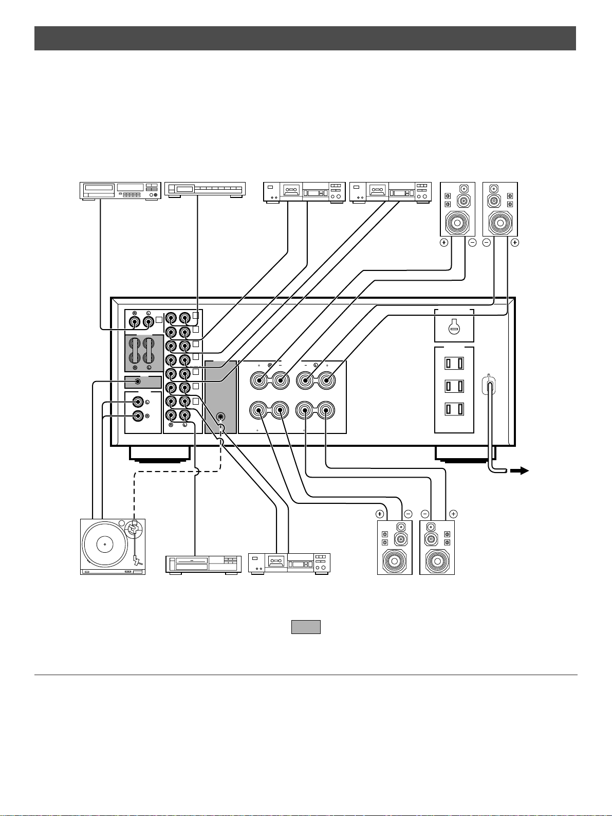
CONNECTIONS
●
Before attempting to make any connections to or from this unit, be sure to first switch OFF the power to this unit and to any other
components to which connections are being made.
●
When making connections between this unit and other components, be sure all connections are made correctly, that is to say L
(left) to L, R (right) to R, “+” to “+” and “–” to “–”. Also, refer to the owner’s manual for each component to be connected to this
unit.
●
If you have YAMAHA components numbered as 1, 2, 3, etc. on the rear panel, connections can be made easily by making
sure to connect the output (or input) terminals of each component to the same-numbered terminals of this unit.
: Refer to “ABOUT THE OTHER REAR PANEL PARTS” on page 5.
TAPE 3
TAPE
PB
3
REC
OUT
4
REMOTE
CONTROL
PHONO
PHONO
SWITCHED
200W MAX. TOTAL
AC OUTLETS
VOLTAGE SELECTOR
GND
CD
TUNER
TAPE
PB
TAPE 1
REC
OUT
TAPE 2
MAIN
IN
PRE
OUT
COUPLER
AUX
A OR B:6
Ω
MIN./SPEAKER
A
B:l2
Ω
MIN./SPEAKER
A
B
SPEAKERS
A
B
A OR B:6
Ω
MIN./SPEAKER
A
B:l2
Ω
MIN./SPEAKER
REMOTE
CONTROL
OUTPUT
GND
OUTPUT
AUDIO OUT
LINE OUT
LINE IN
2
3
4
TAPE
PB
3
REC
OUT
4
1
LINE OUT
LINE IN
LINE OUT
LINE IN
OUTPUT
Compact disc player
Turntable Video cassette player,
LD player, etc.
Tape deck 3 Speakers B
To AC outlet
(General model)
Right Left
Right Left
Tuner Tape deck 1 Speakers A
AC OUTLETS (3 SWITCHED OUTLETS)
Use these to connect the power cords from your components
to this unit.
The power to the SWITCHED outlets is controlled by this unit’s
POWER switch or the provided remote control transmitter’s
POWER key. These outlets will supply power to any
component whenever this unit is turned on.
The maximum power (total power consumption of
components) that can be connected to the SWITCHED AC
OUTLETS is 200 watts.
Tape deck 2
5
English
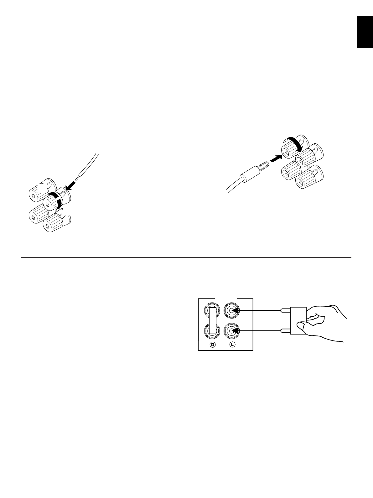
Connect the SPEAKERS terminals to your speakers with wire
of the proper gauge, cut as short as possible. If the
connections are faulty, no sound will be heard from the
speakers. Make sure that the polarity of the speaker wires is
correct, that is, + and – markings are observed. If these wires
are reversed, the sound will be unnatural and will lack bass.
Do not let the bare speaker wires touch each other and do
not let them touch the metal parts of this unit as this could
damage this unit and/or speakers.
How to Connect:
Red: positive (+)
Black: negative (–)
➀
Unscrew the knob.
➁
Insert the bare wire.
[Remove approx. 5mm
(1/4”) insulation from
the speaker wires.]
➂
Tighten the knob and
secure the wire.
●
One or two speaker systems can be connected to this unit.
If you connect only one speaker system, connect it to either
the SPEAKERS A or B terminals.
●
Use speakers with the specified impedance shown on the
rear of this unit.
●
<General model only
>
Banana Plug connections are also possible. Simply insert
the Banana Plug connector into the corresponding terminal.
CONNECTING SPEAKERS
ABOUT THE OTHER REAR PANEL PARTS
REMOTE CONTROL (PHONO) connector
If you have a YAMAHA turntable with a terminal for remote
control, connect it to this connector by using the cable provided
with the turntable. This connection allows you to control the
turntable from the provided remote control transmitter.
GND terminal (For turntable use)
Connecting the ground wire of the turntable to this terminal will
normally minimize hum, but in some cases better results may
be obtained with the ground wire disconnected.
PRE OUT/MAIN IN terminals
Removing the jumper pins enables this unit to independently
perform the functions of a control amplifier and a power
amplifier. These terminals are for connection of a signal-
processing system such as a graphic equalizer or sound
processor.
If a sound processor or other external unit is connected
between these terminals, the VOLUME control of this unit can
be used for overall adjustment of the level of sound.
To connect such a unit, remove the jumper pins from the PRE
OUT/MAIN IN terminals, connect the inputs of that unit to the
PRE OUT terminals and its outputs to the MAIN IN terminals.
For details, refer to the owner’s manual included with the unit
to be connected.
Notes
●
If you will not use the PRE OUT/MAIN IN terminals, never
remove the jumper pins from these terminals. If removed,
no sound will be output from this unit.
●
If you will use this unit with an external unit connected
between the PRE OUT and MAIN IN terminals, make sure
that the PURE DIRECT switch on the front panel is turned
off.
●
If you will use this unit as a power amplifier, connect the
outputs of an external control amplifier etc. to this unit’s
MAIN IN terminals. In that case, this unit’s controls will not
function except the PHONES jack and the SPEAKERS
switches, so use the controls on the external control
amplifier to make volume adjustment etc.
1
2
3
MAIN
IN
PRE
OUT
COUPLER
 Loading...