


AW-PW22
Fully Automatic
AM/FM Power Antenna
Installation Instruction
REPRODUCTION OF EDITORIAL OR PICTORIAL CONTENT IS STRICTLY PROHIBITED WITHOUT WRITTEN CONSENT OF METRA/ROADWORKSTM
|
|
MOUNT |
NUT |
|
|
MOUNT |
|
WASHER |
MOUNT |
PACER |
|
1“ (25mm) HOLE |
|
|
|
|
|
FLUSH ADJUSTABLE |
3’’ |
8’’ |
15 ’ |
23’’ |
30’’ |
ANGLE BASE |
|
FIXED ANGLE BAS |
|
|
|
|
|
|
|
||
G |
|
GAS |
|
|
|
|
|
|
7 |
/ (22mm) HOLE |
|
FIG. 1
RE ER
COAXIAL CABLE
UN IDE
OF FENDER
5/8” / 16mm HOLE 
ELECTRICAL
WIRES
MAST TUBE
MOTOR
ASSE
D
ME TRAP
This antenna is designed for optimum performance for either AM or FM bands. The antenna is raised or lowered by operating the radio on/off switch.
Prior to installing the antenna, read the entire installation instructions.
May require an extension cable depending on vehicle or an antenna adapter cable for many 1995-up Ford, 1988-up GM and some imports.
1.REPLACEMENT OF EXISTING POWER ANTENNA, REMOVING OLD ANTENNA.
A)Gain access to the underside of the fender area through the trunk, fender splash panel, etc.
B)Remove mounting bracket, drain tube, electrical wire and antenna coaxial cable.When removing electrical wires and coaxial cable from the antenna, follow to the closest connector and disconnect.
DO NOT CUT COAXIAL CABLE.
C)Disassemble the mounting base and save the parts, they may be used with the installation of the new antenna.
D)Remove old antenna from below fender.
E)To avoid cutting car wiring, you may want to cut the connector off of the old antenna removed from the car, attaching the new antenna wiring to the old connector wires and directly plug into car wiring.
2. NEW ANTENNA INSTALLATION:
For first time antenna installations:
A)Use original factory hole or select a location on the front or back fender of car for mounting antenna. In selecting the location, make sure the underside of the fender is free of any obstruction such as weld beads, braces, gussets and sub-fender.Also, be sure that sufficient clearance is available under fender to house the antenna, approximately 11-1/2” / 29cm.
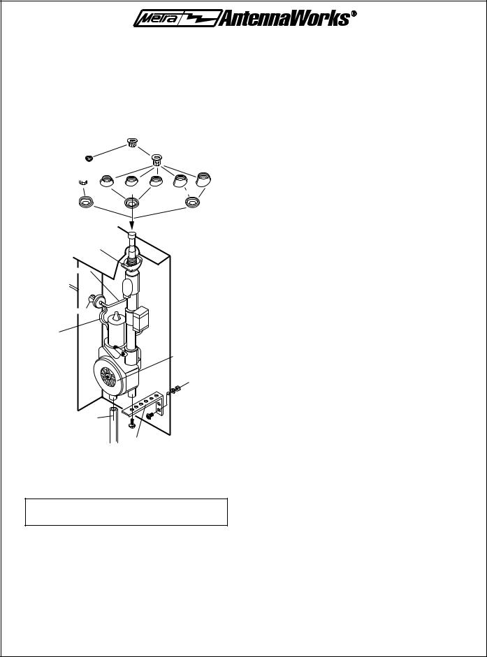
B)Six mounting bases are provided with the antenna. Five fixed angle and one adjustable angle flush mount base. (See Figure 1).
C)Remove the installed flush mounting base from new antenna. Select the proper base with correct angle for fender (as shown in figure 1) or reuse original mounting base previously removed from old antenna. NOTE: The five fixed angle bases require a 7/8” /
22mm hole. The adjustable angle flush base requires a 1” 25mm hole.
D)A 1/8” / 3mm pilot hole should be drilled, then enlarged with a hole saw or drill bit to the proper size.
E)Remove all burrs, paint, road dirt or undercoating from around the underside of the hole.
F)Install the antenna from the underside of the fender and assemble the base above the fender according to Figure 1. BE SURE THE RETAINER RESTS EVENLY ON THE UNDERSIDE OF THE FENDER TO ALLEVIATE ANY POSSIBLE DAMAGE TO THE VEHICLE. Align the mast vertically by slightly tightening the antenna mounting nut while adjusting the mast to be vertical.
G)To prevent movement and maintain the desired angle, secure the bottom of the motor assembly with the supplied perforated strap. Holes are provided with the strap to accommodate various mounting positions. It may be necessary to bend the strap to conform to the fit of the antenna and car. Be sure the antenna retainer is grounded to the underside of the
fender and the black ground wire is grounded properly to the vehicle chassis. If the retainer and ground wire are not properly grounded, THE ANTENNA WILL NOT FUNCTION.
H)With the bottom of the antenna motor assembly secured, the mast at the desired angle and the retainer resting evenly on the underside of the fender, tighten the mounting nut firmly to secure the entire antenna assembly. Do not tighten the nut excessively as this may strip or break the mounting threads or damage contact spring and cause improper antenna operation.
I)Attach the drain lube to the bottom of the motor assembly and route to the outside of the car. Avoid any kinks or bends in the tube that may restrict drainage. (as shown in figure 1.)
For new antenna installations:
J) Route electrical wiring and coaxial cable into the dash area of the vehicle interior as shown in Figure 2. (44-PWEC157 extension cable may be required). A 5/8” / 16mm hole may be required in the interior panel when routing wire from front fender. If possible, avoid routing coaxial cable into engine compartment. The electrical noise found in this area may be transmitted into the antenna wiring.
1

3. ANTENNA WIRING
For first time antenna installations:
A)Radios with switched antenna wire: Connect blue wire from antenna to the switched antenna wire from radio (normally blue) as shown in Figure 2. Connect coaxial cable from antenna to radio.
B)The red power wire from antenna can be connected at fuse block. (as shown in figure 2) battery, or hot side of ignition switch or any other +12 volt “constant on” location.
4. MAST REPLACEMENT
Contact dealer for mast replacement model number.
A)Remove antenna mounting nut (Figure A)
B)To remove mast, turn radio switch on to raise antenna. Remove mast, serrated plastic cable and contact spring. Save and clean contact spring for re-use. Note which side of antenna serrated cable is facing (Figure B).
C) Insert serrated cable of new mast into the housing. Stop when resistance is felt, approximately 12” 30mm. The serrated side of cable must duplicate original direction.
D)Turn radio switch off to lower antenna until serrated cable catches. It may be necessary to cycle antenna several times (by turning radio switch on and off) until cable catches the gear mechanism and retracts (Figure C).
E)Reinstall mast into housing and place contact spring onto mast with flanged end up (Figure D).
F)Reinstall antenna mounting nut and tighten.
G)The mast may only retract or extend halfway. Cycle several times (by turning radio switch on and off) until the mast fully extends and retracts.
IMPORTANT NOTES
1.Maintenance: For best operation and reception, periodically clean mast (while fully extended) with a damp cloth, approximately once a month. Do not oil or grease antenna or motor assembly.
2.Power antenna is designed to withstand extremely cold temperatures, but under severe icing conditions, the antenna could fail to extend or retract. Should this occur, turn the radio on and off three or four times to help free the antenna mast. The antenna motor will not be damaged if mast does not extend. A special clutch protects the motor from
possible damage.
3.Remember to retract antenna when entering a car wash, garages or low clearance areas.
4.There are no serviceable parts in the motor assembly and it should not be taken apart. Warranty will be invalid if damage is caused by unauthorized accessories, disassembly or for wiring methods other than those recommended.
5.Periodically inspect drain tube for blockage or kinks.
6.Use a 5 amp fuse in case of replacement to avoid damage to the motor.
2
AW-PW22
Instructions pour I’installation d’une Antenne électrique AM/FM entièrement automatique
TOUTE REPRODUCTION DE TEXTES, SCHEMAS OU GRAPHIQUES EST STRICTEMENT INTERDITE SAN L’AUTORISATION PREALABLE DE METRA/ROADWORKS MD.
BASE Å ANGLE RÉGLABLE  PO MONTAGE
  Å RAS DANS UN O
DE 1 PO/25MM
|
ÉCRO |
DE MONTAGE |
|
|
RONDEL E MONTAGE |
CALE DE´ ESPACEMENT |
|||
|
|
|
DE MONTAGE |
|
3 ’ |
8’’ |
15 ’ |
23 ’ |
30 ’ |
BAS |
NGLE FIXE ORI |
E D |
1/8 PO |
|
GARN |
GARN |
|
|
|
S
PO ANTENNE
CÃ
D |
US |
D |
L´ AILE |
ORIFICE DE 5/8 PO/16MM
FILS ÉLECTRI
M AGE DU
M UR
TUBE
D´ ÉCOULEMENT
BANDE DE MÉTAL
Cette antenne e été conçue pour donner un rendement optimal tant sur la bande de modulation d’amplitude (AM) que sur la bande de modulation de fréquence (FM). L’antenne peut être élevée ou abaissée en levant ou en baissant le bouton d’interrupteur de la radio.
Avant D’Installer L’Antenne, Bien Lire Toutes Les Instructions Sur Son Installation.
II peut être nécessaire d’ajouter un câble d’allongement sur certains véhicules, ou encore, un câble d’adaptation pour antenne sur de nombreux véhicules GM de modèles 1988 et plus récents, Ford, modèles 1995 et plus récents et sur certaines voitures importées.
1. REMPLACEMENT D’UNE ANTENNE ELECTRIQUE, ENLEVEMENT DE L’ANTENNE USEE
A)Accéder a l’emplacement sous l’aile en passant par la valise, l’aile.
B)Enlever les fixations de montage, tube d’écoulement, fil électrique et câble Coaxial d’antenne. A l’enlèvement des fils électriques et du câble coaxial de l’antenne, suivre le connecteur le plus proche et débrancher. NE PAS COUPER LE CABLE COAXIL.
C)Démonter la base de montage et conserver les pièces en cas qu’elles soient utiles pour le montage de la nouvelle antenne.
D)Retirer I’ antenne usée en la passant sous I’aile.
E)Afin d’éviter de couper le câblage du véhicule, il est préférable de couper le connecteur de l’antenne usée une fois retirée du véhicule et d’attacher le câblage de la nouvelle antenne aux fils du connecteur en questions puis de brancher directement au câblage du véhicule.
2. INSTALLATION DE LA NOUVELLE ANTENNE Installation initiale d’une antenne
A)Utiliser l’orifice original fait par l’usine ou choisir un emplacement sur l’aile avant ou arrière du véhicule pour le montage de l’antenne. En choisissant l’emplacement sur l’aile avant ou arrière du véhicule pour le montage de l’antenne. En choisissant l’emplacement, s’assurer que le dessous de l’aile est libre de toutes obstructions telles que de matériaux s’apport dépose ou de soudage, fixations, goussets d’assemblage et soubassement de l’aile. S’assurer également qu’il y ait un espace libre suffisant sous l’aile, soit environ 11-1/2 po (29cm) pour loger l’antenne.
B)Six bases de montage sont fournies avec l’antenne, cinq à angle fixe et une réglable pour montage a ras. (schéma 1)
C)Enlever la base de montage à ras installe de l’antenne neuve. Choisir la base et la garniture appropriées ainsi que le porteantenne convenant a la base choisie (schéma 1) ou réutiliser la base de montage originale qui a été retirée de l’antenne usée. REMARQUE : Les cinq bases à angle fixe exigent un orifice de 7/8 po (22mm). La base à angle réglable pour montage a ras requiert in orifice de 1 po (25mm).
D)Avec l’une ou l’autre dimension d’orifice, un orifice pilote de 1/8 po/3 mm doit être fait a l’aide d’une perceuse, puis élargi a l’aide d ; une scie sauteuse ou d’un foret a la dimension appropriée pour la base choisie.
E)Eliminer toutes les bavures, peinture, saletés de la route ou couche de fond autour du dessous de l’orifice.
F)Installer ‘antenne en passant par le dessous de l’aile er assembler la base sur le dessus de l’aile (en suivant le schéma 1). S’ASSURER QUE KE ORTE-ANTENNE REPOSE UNIFORMEMENT CONTRE LE DESSOUSE DE L’AILE POUR ALLEGER TOUT DOMMAGE POSSIBLE AU VEHICULE. Aligner le mat verticalement en serrant légèrement l’écrou de montage de l’antenne tout en ajustant le mat pour qu’il soit à la verticale.
G)Pour empêcher l’antenne de se déplacer et pour maintenir l’angle voulu, bien fixer la base de l’assemblage du moteur a l’aide de la bade perforée. Les orifices de la bande permettent un montage à diverses positions. II peut être nécessaire de courber la bande pour l’ajuster à l’antenne et au véhicule. S’assurer que le porte-antenne est mis e la masse au dessous de l’aile et que le fil de terre noir est adéquatement mis a la masse au châssis du véhicule. Si le porteantenne et le fil de terre ne sont pas mis à la masse de façon appropriée, l’antenne ne fonctionnera pas.
H)Une fois la base de l’assemblage du moteur de l’antenne bien fixée, le mat place a l’angle voulu et le porte-antenne reposant uniformément contre le dessous de l’aile, serrer fermement l’écrou de montage pour bien fixer le montage complet de l’antenne. Ne pas trop serrer l’écrou de crainte de briser ou de fausser le filetage de montage ou d’endommager le ressort de contact causer ainsi un mal fonctionnement de l’antenne.
I)Fixer le tube d’ecoulement au bas de l’assemblage du moteur et l’acheminer vers l’antérieur du véhicule. Eviter tout entortillement ou pliage du tube pouvant restreindre l’écoulement. (schéma 1)
Pour l’installation d’une nouvelle antenne
J) Acheminer le cablage électrique et le câble coaxial dans le tableau de bord de l’intérieur du véhicule (tel que montre au schéma 2. Un câble d’allongement AW-PWEC157 peut être requis). Un orifice de 5/8 po (16mm) peut âtre nécessaire dans le panneau
3
 Loading...