


Reclosers
Kyle® Form 5, Form 5 UDP, Form 5 DC NOVA |
Service Information |
Microprocessor-Based Recloser Controls |
S280-79-10 |
Installation and Operation Instructions |
Applicable to serial numbers above 3000 or beginning with CP57.
|
|
|
|
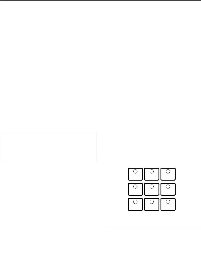
Figure 1. |
99001KM |
|
|
Kyle® Form 5/UDP microprocessor-based recloser control. |
|
|
|
|
|
Contents |
|
Safety Information . . . . . . . . . . . . . . . . . . . . . . . |
. . 2 |
Product Information . . . . . . . . . . . . . . . . . . . . . . . |
. 3 |
Introduction . . . . . . . . . . . . . . . . . . . . . . . . . . . . . . |
. 3 |
ANSI Standards . . . . . . . . . . . . . . . . . . . . . . . . . . |
. 3 |
Quality Standards . . . . . . . . . . . . . . . . . . . . . . . . . |
. 3 |
Acceptance and Initial Inspection . . . . . . . . . . . . . |
. 3 |
Handling and Storage . . . . . . . . . . . . . . . . . . . . . . |
. 3 |
Battery Replacement . . . . . . . . . . . . . . . . . . . . . . |
. 3 |
Control Power . . . . . . . . . . . . . . . . . . . . . . . . . . . . |
. 3 |
Initializing the Control . . . . . . . . . . . . . . . . . . . . . . |
. 4 |
Form 5 Control Description . . . . . . . . . . . . . . . . . |
. 5 |
Recloser Interface (RIF) Module . . . . . . . . . . . . . |
. 6 |
Central Processing Unit (CPU) Module . . . . . . . . |
. 6 |
Discrete Interface (DIF) Module . . . . . . . . . . . . . . |
. 6 |
Power Supply Module . . . . . . . . . . . . . . . . . . . . . . |
. 6 |
Form 5 Control Operator Panel . . . . . . . . . . . . . . |
. 7 |
Battery Test Procedure . . . . . . . . . . . . . . . . . . . . . |
. 14 |
Control Features . . . . . . . . . . . . . . . . . . . . . . . . . . |
. 14 |
Communications . . . . . . . . . . . . . . . . . . . . . . . . . . |
. 19 |
Auxiliary Power for Accessories . . . . . . . . . . . . . |
. 20 |
Recloser Interface (RIF) Module Configuration |
. . 20 |
Form 5 Universal Device Protection (UDP) |
|
Control . . . . . . . . . . . . . . . . . . . . . . . . . . . . . . . . . . |
. 21 |
Form 5 DC NOVA Control . . . . . . . . . . . . . . . . . . |
. 22 |
Discrete Interface (DIF) Accessory . . . . . . . . . . . |
. 23 |
Customer Connection Information . . . . . . . . . . . . |
. 23 |
Standard and UDP DIF Module 1 Inputs . . . . . . . . |
26 |
Standard and UDP DIF Module 1 Outputs . . . . . . . |
28 |
Standard and UDP Module 2 Inputs . . . . . . . . . . . . |
29 |
Standard and UDP Module 2 Outputs . . . . . . . . . . |
30 |
Input Accuracy . . . . . . . . . . . . . . . . . . . . . . . . . . . . |
31 |
Installation Procedure . . . . . . . . . . . . . . . . . . . . . . |
32 |
Initial Programming Prior to Installation . . . . . . . . . |
32 |
Control / Recloser Compatibility . . . . . . . . . . . . . . . |
32 |
Control Cable . . . . . . . . . . . . . . . . . . . . . . . . . . . . . |
32 |
Mounting the Control . . . . . . . . . . . . . . . . . . . . . . . |
33 |
Grounding the Control . . . . . . . . . . . . . . . . . . . . . . |
34 |
Customer Connections for AC Power . . . . . . . . . . . |
38 |
Customer Connections for Metering . . . . . . . . . . . . |
38 |
Before Placing Control and Recloser into Service |
. 42 |
Testing and Troubleshooting . . . . . . . . . . . . . . . . |
43 |
Testing an Installed Control . . . . . . . . . . . . . . . . . . |
43 |
Testing with Type MET Tester . . . . . . . . . . . . . . . . |
43 |
Closing the Recloser During Testing . . . . . . . . . . . |
44 |
Form 5 Control Default Test Procedure . . . . . . . . |
47 |
Remove the Control from Service . . . . . . . . . . . . . |
55 |
Return the Control to Service . . . . . . . . . . . . . . . . |
55 |
Additional Information . . . . . . . . . . . . . . . . . . . . . . |
56 |
November 2001 • Supersedes 1/01 |
1 |
Printed in USA
Kyle Form 5, Form 5 UDP, Form 5 DC NOVA Recloser Control Installation and Operation Instructions
! |
SAFETY FOR LIFE |
! |
SAFETY |
SAFETY |
|
FOR LIFE |
FOR LIFE |
Cooper Power Systems products meet or exceed all applicable industry standards relating to product safety. We actively promote safe practices in the use and maintenance of our products through our service literature, instructional training programs, and the continuous efforts of all Cooper Power Systems employees involved in product design, manufacture, marketing, and service.
We strongly urge that you always follow all locally approved safety procedures and safety instructions when working around high voltage lines and equipment and support our “Safety For Life” mission.
SAFETY INFORMATION
The instructions in this manual are not intended as a substitute for proper training or adequate experience in the safe operation of the equipment described. Only competent technicians who are familiar with this equipment should install, operate, and service it.
A competent technician has these qualifications:
•Is thoroughly familiar with these instructions.
•Is trained in industry-accepted highand low-voltage safe operating practices and procedures.
•Is trained and authorized to energize, de-energize, clear, and ground power distribution equipment.
•Is trained in the care and use of protective equipment such as flash clothing, safety glasses, face shield, hard hat, rubber gloves, hotstick, etc.
Following is important safety information. For safe installation and operation of this equipment, be sure to read and understand all cautions and warnings.
Hazard Statement Definitions
This manual may contain four types of hazard statements:
! |
DANGER: Indicates an imminently haz- |
|
ardous situation which, if not avoided, will |
||
result in death or serious injury. |
||
! |
WARNING: Indicates a potentially hazardous |
|
situation which, if not avoided, could result in |
||
|
||
death or serious injury. |
||
|
CAUTION: Indicates a potentially hazardous |
|
! |
||
situation which, if not avoided, may result in |
||
|
||
minor or moderate injury.
CAUTION: Indicates a potentially hazardous situation which, if not avoided, may result in equipment damage only.
Safety Instructions
Following are general caution and warning statements that apply to this equipment. Additional statements, related to specific tasks and procedures, are located throughout the manual.
! |
DANGER: Hazardous voltage. Contact with haz- |
|
ardous voltage will cause death or severe per- |
||
|
sonal injury. Follow all locally approved safety procedures when working around high and low voltage
lines and equipment. |
G103.3 |
! |
WARNING: Before installing, operating, main- |
|
taining, or testing this equipment, carefully read |
||
|
and understand the contents of this manual. Improper operation, handling or maintenance can result in death, severe personal injury, and equipment damage. G101.0
! |
WARNING: This equipment is not intended to |
protect human life. Follow all locally approved pro- |
cedures and safety practices when installing or operating this equipment. Failure to comply can result in death, severe personal injury and equipment damage.
G102.1
! |
WARNING: Power distribution equipment must |
be properly selected for the intended application. It |
must be installed and serviced by competent personnel who have been trained and understand proper safety procedures. These instructions are written for such personnel and are not a substitute for adequate training and experience in safety procedures. Failure to properly select, install, or maintain power distribution equipment can result in death, severe personal injury, and equip-
ment damage. |
G122.2 |
2

!
SAFETY FOR LIFE
S280-79-10
PRODUCT INFORMATION
Introduction
Service Information S280-79-10 provides installation and operation instructions for the Kyle Form 5 and Form 5 UDP microprocessor-based electronic recloser controls.
Read This Manual First
Read and understand the contents of this manual and follow all locally approved procedures and safety practices before installing or operating this equipment.
Additional Information
These instructions cannot cover all details or variations in the equipment, procedures, or process described, nor provide directions for meeting every possible contingency during installation, operation, or maintenance. When additional information is desired to satisfy a problem not covered sufficiently for the user's purpose, please contact your Cooper Power Systems sales representative.
ANSI Standards
Kyle reclosers are designed and tested in accordance with the following ANSI standards: C37.60 and C37.85 and ANSI Guide C37.61.
Quality Standards
ISO 9001:2000-Certified Quality Management System
Acceptance and
Initial Inspection
Each Form 5 control is completely assembled, tested, and inspected at the factory. It is carefully calibrated, adjusted and in good condition when accepted by the carrier for shipment.
Upon receipt, inspect the carton for signs of damage. Unpack the control and inspect it thoroughly for damage incurred during shipment. If damage is discovered, file a claim with the carrier immediately.
Handling and Storage
Be careful during handling and storage of the control to minimize the possibility of damage. If the control is to be stored for any length of time prior to installation, provide a clean, dry storage area. If storage is in a humid atmosphere, make provisions to keep the control circuitry energized.
Note: To energize the control, apply AC power to the AC supply input connector block TB1 located left of the Recloser Interface (RIF) module within the control. Refer to the Customer Connection for AC power section in this manual.
Control Battery Storage and Charging
The 24 Vdc control battery in the Form 5 control is fully charged prior to shipment and is ready for use. In order to maintain sufficient charge to operate the control, the sealed lead acid battery should be charged after no more than three months of storage.
Note: Two 12 Vdc, 13 amp-hour batteries are available for use with the Form 5 Distribution Automation upgrade accessory.
Temperature has an effect on battery life. Sealed lead acid batteries should be stored, fully charged, at room temperature. Never store lead acid batteries at temperature exceeding 47°C (117°F), as damage can result in approximately one month.
IMPORTANT: To maintain sufficient charge to operate the control and prevent battery cell damage, the sealed lead-acid batteries should be charged after no more than three months of storage.
To keep the battery charged, energize the control’s builtin charger with AC power applied to the user AC supply input connector block TB1, located left of the RIF module within the control cabinet.
Note: When shipped from the factory, the battery source is disconnected and its output plugs are taped to the cabinet. Connect the battery plugs into the mating connectors to complete the battery circuit.
IMPORTANT: Connect the control battery when AC power is connected to the control’s AC supply Input Terminal Block. The battery must be disconnected prior to shipping or storing the control.
Battery Replacement
The 24 Vdc control battery has a life expectancy of 4 to 6 years. It is recommended that the battery be replaced after 4 years.
Control Power
The primary source of power is factory configured for 120 Vac or 240 Vac. The 240 Vac version is available as an option at time of order entry. Primary power is rectified to charge the power capacitor and to power the dc/dc converter that provides power to the control. A minimum of 500 mA of ac current is required for heater operation, battery charging current, and to keep all modules energized.
3
Kyle Form 5, Form 5 UDP, Form 5 DC NOVA Recloser Control Installation and Operation Instructions
AC Reclosers
Power to operate the tripping and closing solenoids in the recloser is provided by the power capacitor located behind the operator panel of the control. A sealed, 24-volt, lead acid battery is located in the lower portion of the control cabinet and is utilized to provide operating and tripping energy when AC power is temporarily lost. The control is equipped with an ac-powered, temperaturecompensated battery charger.
Operation Upon Loss Of AC Power
If the control is equipped with the standard 24 Vdc leadacid battery, the control maintains full operation from the battery power supply for a minimum of 32 hours at 20°C (24 hours at -40°C). To prevent battery damage, the control shuts down automatically upon detection of low battery voltage below 22.7 Vdc.
Control programming settings and parameters—including event recorder, duty monitor, and data profile metering parameters—are stored in non-volatile memory and retained upon loss of control power. The time/date clock resets to 0:00:00, 1970 upon loss of control power.
The AC power LED indicator on the operator panel of the control will turn off after 15 seconds upon loss of AC power. The indicator will illuminate immediately upon return of ac power.
Initializing the Control
Two methods are available to initialize the Form 5 control.
Method 1: Connect AC power to the input connector terminal TB-1. Refer to the Customer Connections for AC Power section of this manual.
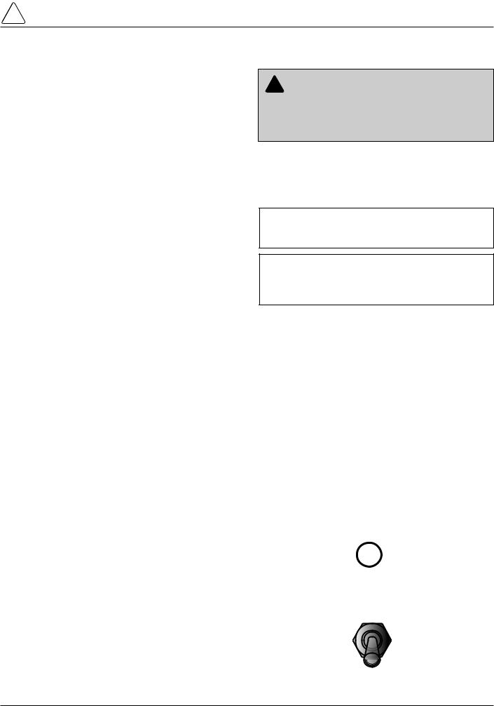
Method 2: Connect the battery terminal on the control and press the MANUAL BATTERY RECONNECT button located on the Form 5 power supply. See Figure 4.
Note: Method 2 powers the control off the battery and is not intended for long term operation.
In both methods, after initialization, set the control clock via the interface software.
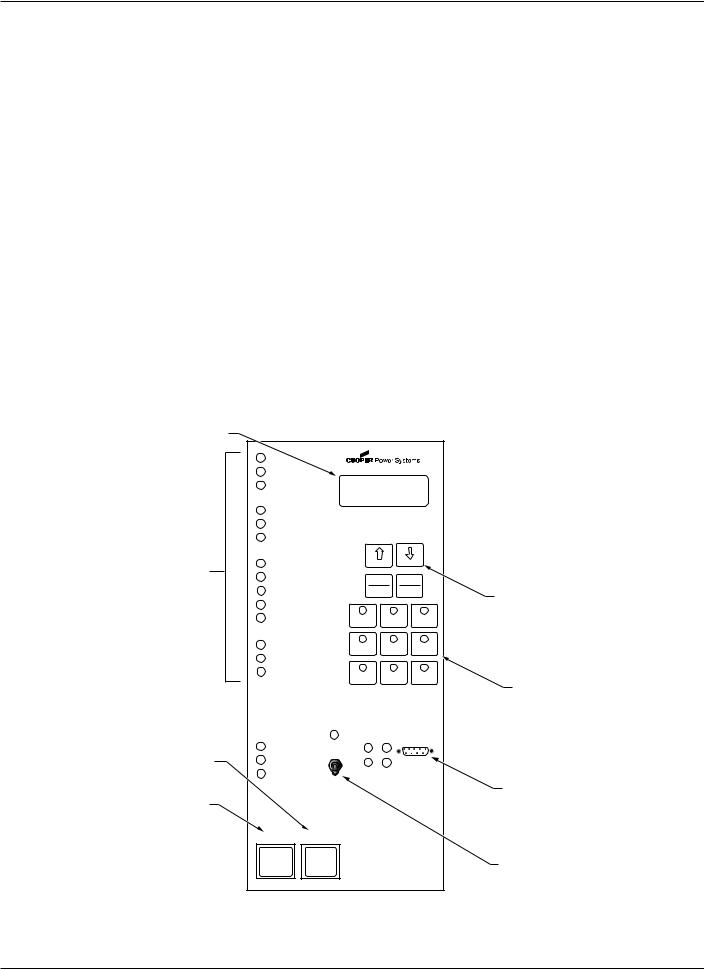
LCD Display
LED Indicators
CLOSE Pushbutton
TRIP (LOCKOUT)
Pushbutton
CONTROL OK |
|
|
|
|
|
|
|
|
|
AC POWER |
|
|
|
|
|
|
|
|
|
ABOVE MIN TRIP |
|
|
|
|
|
|
|
|
|
CHECK BATTERY |
|
|
|
|
|
|
|
|
|
RECLOSER MALFUNCTION |
|
|
|
|
|
|
|
||
REVERSE POWER FLOW |
|
|
|
|
|
|
|
||
BUSHINGS 1-2 FAULT TARGET |
|
BACK |
|
NEXT |
|
|
|||
|
|
|
|
|
|
|
|||
BUSHINGS 3-4 FAULT TARGET |
|
RESET |
CHANGE |
|
|||||
|
|
|
|
TARGETS |
|
||||
BUSHINGS 5-6 FAULT TARGET |
|
RESET |
|
LAMP |
|
|
|||
|
MAX CURRENT |
|
TEST |
|
|
||||
GROUND FAULT TARGET |
|
|
|
|
|
|
|
||
SENSITIVE-GROUND FAULT TARGET |
GND TRIP |
NON |
|
SUPERVISORY |
|||||
|
|
|
BLOCKED |
RECLOSING |
BLOCKED |
||||
BUSHINGS 1-2 VOLTAGE |
COLD LOAD |
BATTERY |
|
FAST |
|||||
|
|
|
PICK UP |
TEST |
|
|
TRIPS |
||
|
|
|
BLOCKED |
|
|
DISABLED |
|||
BUSHINGS 3-4 VOLTAGE |
|
|
|
||||||
|
|
|
|
|
|
|
|||
BUSHINGS 5-6 VOLTAGE |
ALTERNATE |
ALTERNATE |
|
ALTERNATE |
|||||
|
|
|
|
PROFILE |
PROFILE |
|
|
PROFILE |
|
|
|
|
|
NO. 1 |
NO. 2 |
|
|
NO. 3 |
|
RECLOSER CLOSED |
HOT LINE |
TX 3 |
TX 2 |
|
|
|
|
||
|
|
|
|
|
|
||||
RECLOSER OPEN |
|
TAG |
ON |
|
|
|
|
|
|
|
|
|
|
|
RS232 |
||||
|
|
|
|
|
|
|
|||
CONTROL LOCKOUT |
|
OFF |
RX 3 |
RX 2 |
|
|
|
|
|
TRIP |
CLOSE |
|
KYLE |
® |
|||||
(LOCKOUT) |
|
|
|
|
|||||
|
|
|
|
|
|||||
|
|
|
|
|
FORM 5 |
|
|
||
|
|
|
RECLOSER CONTROL |
||||||
LCD Display Dedicated
Function Keys
Operation "Hot Keys"
RS232 Data Port
Hot Line Tag
Figure 2. |
99005KM |
Form 5 recloser control operator panel. |
|
4

!
SAFETY FOR LIFE
S280-79-10
FORM 5 CONTROL DESCRIPTION
Current sensing is provided by three current transformers located in the recloser and interfaced to the Form 5 control via the control cable. This cable also supplies Trip, Close, and Recloser status, and connects to the Recloser Interface (RIF) module to provide isolation for reliable operation. Voltages for metering are also connected to the RIF module via the connector terminal block, TB-1 (Figure 3).
A functional block diagram of the Form 5 control is shown in Figure 3. Line current flowing through the recloser is converted by the CPU module to a digital signal suitable for metering and fault current calculations. Data sampling occurs at a rate 32 times per cycle. The CPU contains a data acquisition section that uses the acquired samples to compute the fundamental currents and voltage for use in overcurrent, under/over voltage and under/over frequency protection, as well as currents and voltages for metering functions. The current for overcurrent protection is calculated on a sub-cycle basis; it includes only the fundamental and DC component. For metering, the fundamental and harmonic current and voltages are determined.
When the phase or ground current exceeds its programmed minimum-trip value and associated time-cur- rent curve (TCC) timing, the control initiates the programmed sequence of recloser tripping and reclosing operations via the CPU and RIF modules. If the fault is temporary, the control ceases to command recloser operations after a successful reclose, and the control resets to the start of its operating sequence after a preset time delay. If the fault is permanent, the control performs its complete programmed sequence of reclose commands and locks out with the recloser open. Once locked out, the control must be closed via the operator panel or SCADA communications. This resets the control to the start of the operating sequence.
The following chain of events occurs for an operating sequence of two trips to lockout:
1.The overcurrent signal is integrated with time on the selected curve for the first trip operation (TCC1) to produce the signal which energizes the trip circuit.
2.Energizing the trip circuit connects the battery and capacitor to the trip solenoid to open the recloser.
3.Upon opening, the control starts timing on the first reclosing interval-delay time.
4.Upon expiration of this reclosing interval-delay, a closing signal is issued from the control, closing the recloser and selecting the time-current characteristics for the second trip operation (TCC2).
5.If current remains above the minimum-trip level, the tripping and reclosing sequence is repeated.
6.The control begins the reset-delay timer if the overcurrent is cleared before the operating sequence reaches lockout indicated by a closed recloser and current below minimum trip.
7.When the reset-delay times out, the control is reset to the home state and is ready for another programmed operating sequence. If current rises above minimum trip prior to the reset-delay timing out, the timer is halted and the control resumes the operating sequence while the accumulated reset-delay timing is restarted.
TB1 TERMINAL BLOCK
CUSTOMER |
|
P.T. INPUTS |
|
|
POWER SUPPLY |
|
|
|
|
BATTERY |
||||
|
|
|
|
|
|
|
||||||||
|
|
|
|
|
|
|
||||||||
|
|
|
|
|
|
|||||||||
|
|
|
|
|
|
|
|
|
|
|
|
|
|
|
|
|
|
|
|
|
|
|
|
|
|
|
|
|
|
|
|
|
|
|
|
|
|
|
|
|
|
|
|
|
|
|
|
|
|
|
|
|
|
|
|
|
|
|
|
|
RECLOSER |
|
|
|
|
RIF |
|
|
|
|
|
|
|
|
|
|
|
|
|
|
|
|
|
|
|
|
|
|
|
|
|
|
|
|
|
|
|
|
|
|
|
|
OPERATOR'S |
|
|
|
|
|
|
|
|
|
|
|
|
|
|
|
|
|
|
|
|
|
|
|
|
|
|
|
|
|
|
|
|
|
|
|
|
|
|
TRIP SOLENOID |
|
|
|
|
OPTICAL |
|
|
|
|
CPU |
|
|
|
|
|
|
DIF#1 |
|
|
|
DIF#2 |
||||
|
|
|
|
|
ISOLATION |
|
|
|
|
|
|
|
PANEL |
|
|
|
|
(OPTIONAL) |
||||||||
|
|
|
|
|
|
|
|
|
|
|
|
|
||||||||||||||
|
|
|
|
|
|
|
|
|
|
|
|
|
|
|
|
(OPTIONAL) |
|
|||||||||
|
|
|
|
|
|
|
|
|
|
|
|
|
|
|
||||||||||||
|
|
|
|
|
|
|
|
|
|
|
|
|
|
|
|
|
|
|
|
|
|
|
||||
|
CLOSE SOLENOID |
|
|
|
|
OPTICAL |
|
|
|
|
|
|
|
|
KEYBOARD |
|
|
|
|
|
|
|
|
|
|
|
|
|
|
|
|
|
|
|
|
|
|
|
|
|
|
|
|
|
|
|
|
|
|||||
|
|
|
|
|
|
ISOLATION |
|
|
|
|
|
|
|
|
|
|
|
|
|
|
|
|
|
|
|
|
|
OPEN / CLOSE |
|
|
|
|
|
|
|
|
|
|
|
|
LED's |
|
|
|
|
|
|
|
|
|
|
||
|
|
|
|
|
OPTICAL |
|
|
|
|
|
|
|
|
|
|
|
|
|
|
|
|
|
|
|||
|
|
|
|
|
|
|
|
|
|
|
|
|
LCD |
|
|
|
|
|
|
|
|
|
|
|||
|
SWITCHES |
|
|
|
|
ISOLATION |
|
|
|
|
|
|
|
|
|
|
|
|
|
|
|
|
|
|
|
|
|
|
|
|
|
|
|
|
|
|
|
|
|
|
|
|
|
|
|
|
|
|
|
|
|
||
|
A Ø CT |
|
|
|
|
|
|
|
|
|
|
|
|
|
|
RS232 PORT |
|
|
|
|
|
|
|
|
|
|
|
|
|
|
|
|
|
|
|
|
|
|
|
|
|
|
|
|
|
|
|
|
|
|
|||
|
|
|
|
|
|
|
|
|
|
|
|
|
|
|
|
|
|
|
|
|
|
|
|
|
|
|
|
|
|
|
|
|
|
|
|
|
|
|
|
|
|
|
|
|
|
|
|
|
|
|
|
|
|
|
|
|
|
|
MATCHING |
|
|
|
|
|
|
|
|
|
|
|
|
|
|
|
|
|
|
|
||
|
B Ø CT |
|
|
|
|
|
|
|
|
|
|
|
|
|
|
|
|
|
|
|
|
|
|
|
||
|
|
|
|
|
TRANSFORMERS |
|
|
|
|
|
|
|
|
|
|
|
|
|
|
|
|
|
|
|
||
|
|
|
|
|
|
|
|
|
|
|
|
|
|
|
|
|
|
|
|
|
|
|
|
|
||
|
C Ø CT |
|
|
|
|
AND SIGNAL |
|
|
|
|
|
|
|
|
|
|
|
|
|
|
|
|
|
|
|
|
|
|
|
|
|
|
|
|
|
|
|
|
|
|
|
|
|
|
|
|
|
|
|
|
|||
|
|
|
|
|
|
CONDITIONING |
|
|
|
|
|
|
|
|
RS232 |
12 |
|
|
|
12 |
|
|
||||
|
|
|
|
|
|
|
|
|
|
|
|
|
|
|
|
|
|
|
|
|
||||||
|
|
|
|
|
|
|
|
|
|
|
|
|
|
|
|
|
|
|
|
12 |
|
|
|
|
12 |
|
|
|
|
|
|
|
|
|
|
|
|
|
|
|
|
|
Or |
|
|
|
|
|
|||||
|
CT COMMON |
|
|
|
|
|
|
|
|
|
|
|
|
|
|
FIBER-OPTIC |
|
|
|
USER |
|
|
USER |
|||
|
|
|
|
|
|
|
|
|
|
|
|
|
|
|
PORT |
|
|
|
|
|
||||||
|
|
|
|
|
|
|
|
|
|
|
|
|
|
|
|
|
|
CONNECTIONS |
|
CONNECTIONS |
||||||
|
|
|
|
|
|
|
|
|
|
|
|
|
|
OPTIONS |
|
|
|
|||||||||
|
|
|
|
|
|
|
|
|
|
|
|
|
|
|
6 unlatched outputs |
6 unlatched outputs |
||||||||||
|
|
|
|
|
|
|
|
|
|
|
|
|
|
|
|
RS232 |
|
|||||||||
|
|
|
|
|
|
|
|
|
|
|
|
|
|
|
|
Or |
|
6 latched outputs |
|
6 latched outputs |
||||||
|
|
|
|
|
|
|
|
|
|
|
|
|
|
|
||||||||||||
|
|
|
|
|
|
|
|
|
|
|
|
|
|
|
|
FIBER-OPTIC |
|
|
12 inputs |
|
|
12 inputs |
||||
PCB
Figure 3.
Form 5 control operational flow diagram.
5
Kyle Form 5, Form 5 UDP, Form 5 DC NOVA Recloser Control Installation and Operation Instructions
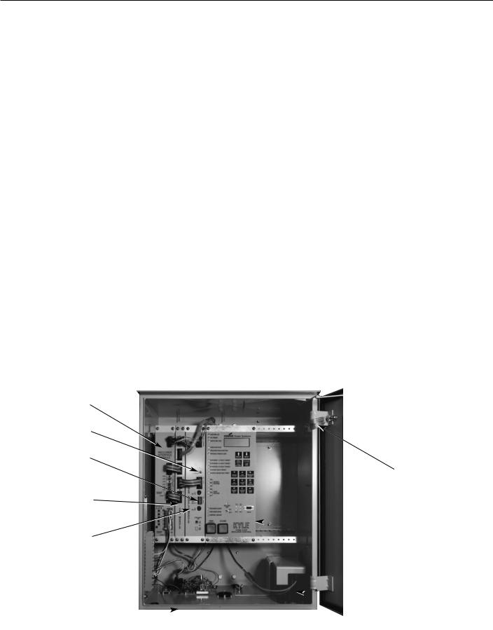
The Form 5 control is constructed in a modular fashion to simplify service and the addition of accessories (Figure 4). The standard configuration incorporates a Central Processing Unit (CPU) module, power supply module, Recloser Interface (RIF) module, and an operator panel.
Discrete Interface (DIF) module(s), the fiber-optic board and the RS-232 communication interface cards may be ordered as accessories. Mounting provisions can be provided to add customer-supplied radio and modem modules.
Central Processing Unit (CPU)
Module
The CPU module is the center of the Form 5 control. The CPU contains a 32-bit micro-controller, a Digital Signal Processor, RAM and EEPROM memory, and a 16-bit analog-to-digital converter. The CPU module accepts 16 analog inputs which it routes through the digital signal processor, which samples 32 times per cycle, to compute harmonic analysis to the 15th harmonic.
Recloser Interface (RIF) Module
The Recloser Interface (RIF) Module provides the interface between the recloser and the CPU module, as well as the interface between the voltage sensors and the CPU module. The RIF is designed to interface with the following reclosers: WE/WVE group, NOVA group, VSA/VSO group, and KFME/KFVME (50Hz) group.
The recloser connector includes three current-trans- former inputs, Open and Closed status sensing, and Trip and Close controls. The voltage sensor connector accepts six voltage inputs; three for source-side, and three for load-side voltage. Two sets of dip switches, located on the RIF front panel, utilize different switch positions to configure the desired voltage. See Figure 17.
The RIF board accepts either 12, 120, or 240 Vac voltage inputs for metering. The factory configuration is outlined on the module label and can be customized to user specification. See RECLOSER INTERFACE (RIF) MODULE CONFIGURATION section of this manual.
Recloser Interface
(RIF) Module
Manual Battery
Reconnect Button
Auxiliary Power
Connection (P9)
Central Processing
Unit (CPU) Module
Power
Supply
Module
TB1 Connector
Block 
Control Cable Receptacle
and Control Grounding Lug
(located beneath cabinet)
Discrete Interface (DIF) Module
The Discrete Interface (DIF) module allows users with existing RTUs the ability to interface with the Form 5 control. The DIF module contains 12 inputs and 12 outputs can be customized for a remote or supervisory function. One Form 5 control can accommodate two DIF modules. See DISCRETE INTERFACE (DIF) ACCESSORY section of this manual.
Power Supply Module
The Power Supply module is designed to accept 100 to 134 Vac or 200 to 268 Vac user-supplied input power at either 50 or 60 Hz.
The Power supply module (connection P9) provides auxiliary power to radio communications units, RTUs and other accessories. The auxiliary output provides 24 Vdc (12 Vdc is available) for user loads. The auxiliary power supply has the capability to provide a load of up to 40 W peak (1 second) and 3 W average. The auxiliary power is fused and current-limited to prevent user loads from disabling the control.
Grounding Strap
 Power Capacitor
(Located behind operator panel)
 Control Battery
Figure 4. |
99001KM |
|
|
|
|
Form 5 UDP control operating panel with interface modules and radio mounting provisions. |
|
|
|
|
|
|
|
|
6
!
SAFETY FOR LIFE
S280-79-10
Form 5 Control Operator Panel
The Form 5 control operator panel (Figure 8) allows local operation and status interrogation through built-in operator controls and status displays. The operator panel contains LED indicators, operational pushbuttons, membrane-type functional/indication switches, backlit LCD display, and Hot Line Tag switch with indication. An RS-232 port is also provided to permit the temporary connection of a PC for programming the parameters in the control.
All indicators with the exception of Hot Line Tag and recloser status are automatically turned off after 5 minutes of operator panel inactivity.
Reactivating is accomplished by pressing any operation switch. The LCD messages will remain while in this power-saving mode, although the illuminating backlight will shut off.
CONTROL OK |
|
|
|
|
|
|
|
|
|
AC POWER |
|
|
|
|
|
|
|
|
|
ABOVE MIN TRIP |
|
|
|
|
|
|
|
|
|
CHECK BATTERY |
|
|
|
|
|
|
|
|
|
RECLOSER MALFUNCTION |
|
|
|
|
|
|
|
||
REVERSE POWER FLOW |
|
|
|
|
|
|
|
||
BUSHINGS 1-2 FAULT TARGET |
|
BACK |
|
NEXT |
|
|
|||
|
|
|
|
|
|
|
|||
BUSHINGS 3-4 FAULT TARGET |
|
RESET |
CHANGE |
|
|||||
|
|
|
|
TARGETS |
|
||||
BUSHINGS 5-6 FAULT TARGET |
|
RESET |
|
LAMP |
|
|
|||
|
MAX CURRENT |
|
TEST |
|
|
||||
GROUND FAULT TARGET |
|
|
|
|
|
|
|
||
SENSITIVE-GROUND FAULT TARGET |
GND TRIP |
NON |
|
SUPERVISORY |
|||||
|
|
|
BLOCKED |
RECLOSING |
BLOCKED |
||||
BUSHINGS 1-2 VOLTAGE |
COLD LOAD |
BATTERY |
|
FAST |
|||||
|
|
|
PICK UP |
TEST |
|
|
TRIPS |
||
|
|
|
BLOCKED |
|
|
DISABLED |
|||
BUSHINGS 3-4 VOLTAGE |
|
|
|
||||||
|
|
|
|
|
|
|
|||
BUSHINGS 5-6 VOLTAGE |
ALTERNATE |
ALTERNATE |
|
ALTERNATE |
|||||
|
|
|
|
PROFILE |
PROFILE |
|
|
PROFILE |
|
|
|
|
|
NO. 1 |
NO. 2 |
|
|
NO. 3 |
|
RECLOSER CLOSED |
HOT LINE |
TX 3 |
TX 2 |
|
|
|
|
||
|
|
|
|
|
|
||||
RECLOSER OPEN |
|
TAG |
ON |
|
|
|
|
|
|
|
|
|
|
|
RS232 |
||||
|
|
|
|
|
|
|
|||
CONTROL LOCKOUT |
|
OFF |
RX 3 |
RX 2 |
|
|
|
|
|
TRIP |
CLOSE |
|
KYLE |
® |
|||||
(LOCKOUT) |
|
|
|
|
|||||
|
|
|
|
|
|||||
|
|
|
|
|
FORM 5 |
|
|
||
|
|
|
RECLOSER CONTROL |
||||||
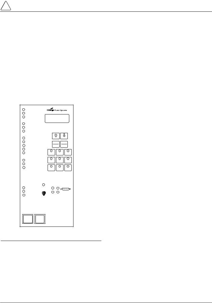
Figure 5.
Form 5 control operator panel.
LED Indicators
The operator panel LED indicators (Figure 5) give instant information on the control and recloser status.
LED indicators include:
CONTROL OK
This green LED is illuminated when the continuous selfdiagnostics of the control have detected no CPU or memory malfunctions and indicate that the control is capable of normal operation.
AC POWER
This green LED is illuminated when the presence of ac input power to the control is sensed. The LED will turn off if ac power is lost for more than 10 seconds.
ABOVE MIN TRIP
This red LED is illuminated when the control detects that current is above the programmed minimum trip value for Bushings 1-2, Bushings 3-4, Bushings 5-6, Ground, or Sensitive Ground.
CHECK BATTERY
This red indicator illuminates for two conditions:
1.Battery voltage is below 20 Vdc or drops 2Vdc or more during battery test.
2.The control fails a manual battery test. The LED will remain on until a successful battery test is completed.
Refer to the Battery Test Procedure in this manual for more information.
RECLOSER MALFUNCTION
This red indicator is illuminated when the control detects a failure in a trip or close operation. It turns off automatically if the recloser returns to the proper state.
REVERSE POWER FLOW
This red indicator illuminates when the control detects power flow from the load side to the source side of the recloser.
Note: Voltage sensor polarity and phase must be correct for reverse power flow to function properly.
BUSHINGS 1-2 FAULT TARGET
BUSHINGS 3-4 FAULT TARGET
BUSHINGS 5-6 FAULT TARGET
GROUND FAULT TARGET
SENSITIVE GROUND FAULT TARGET
These red target LEDs illuminate when the control issues an overcurrent trip signal while the respective phase current or ground current exceeds the minimum pickup value. Reset is accomplished automatically when Auto Reset is activated and a successful close operation is performed or manual reset is accomplished by pressing the RESET TARGETS button on the control operator panel.
BUSHINGS 1-2 VOLTAGE
BUSHINGS 3-4 VOLTAGE
BUSHINGS 5-6 VOLTAGE
These red voltage LEDs illuminate when the control detects the presence of voltage on the respective bushings as connected to TB1. Refer to the Customer Connections for AC Power section in these instructions to determine the appropriate power connections.
RECLOSER CLOSED
This red indicator is illuminated when the control senses that the recloser mechanism is in the closed position.
7

Kyle Form 5, Form 5 UDP, Form 5 DC NOVA Recloser Control Installation and Operation Instructions
RECLOSER OPEN
This green indicator is illuminated when the control senses that the recloser mechanism is in the open position.
CONTROL LOCKOUT
This green indicator is illuminated when the recloser is open and a reclosing sequence is not in progress or when the lockout handle on the recloser mechanism is in the down position; i.e., trip and close circuits are open.
Note: The RECLOSER MALFUNCTION, RECLOSER OPEN, RECLOSER CLOSED, and RECLOSER LOCKOUT LEDs will flash upon detection of a trip failure. See the Control Features section of this manual.
TRIP (Lockout) Pushbutton
The TRIP pushbutton (Figure 2) provides front-panel access to trip (lockout) the recloser. When pressed, the TRIP push-button opens the recloser and locks out the control.
CLOSE Pushbutton
When pressed, the CLOSE pushbutton (Figure 2) returns the control to the initial or home position, closing the recloser. The control is ready for the start of a new trip/close sequence.
Note: Pressing the CLOSE pushbutton from the Lockout position, will initiate Cold Load Pickup (CLPU) protection, if the feature is first enabled from the interface software Protection Profile screen, and the COLD LOAD PICKUP BLOCKED LED on the operator panel is not lit.
If the recloser is closed, pushing the CLOSE pushbutton has no effect on the control. Depressing and holding the CLOSE pushbutton does not activate the Cold Load Pickup feature. See Cold Load Pickup in the Control Features section of this manual.
The Form 5 control has a Manual Close Delay feature that provides an interval of time from when the CLOSE pushbutton is depressed to the time when manual close operation is performed. See Manual Close Delay in the Control Features section of this manual.
LCD Display
The control operator panel has a large, backlit LCD display (Figure 6) used for viewing control parameters and monitoring system conditions. Data is organized into screens of information, with each display containing four lines of information, with up to 20 characters per line. Access to the screens is obtained through navigational keys which permit the user to scroll through the menu in a timely and efficient manner.
When an overcurrent trip occurs, the control automatically displays the fault current values as shown on the LCD display as Screen 1. Refer to LCD Display Screens section of this manual.
NEXT Key
Pressing the NEXT key causes the LCD display to scroll to the next screen of available information. Pressing and holding the NEXT key causes the control to scroll to subsequent screens at the rate of about two screens per second.
NEXT |
BACK |
|
RESET |
CHANGE |
|
TARGETS |
||
|
||
RESET |
LAMP |
|
MAX CURRENT |
TEST |
|
|
Figure 6.
LCD display and dedicated function keys.
BACK Key
Pressing the BACK key causes the LCD display to scroll to the previous screen of available information. Pressing and holding the BACK key causes the control to scroll to previous screen.
RESET TARGETS/RESET MAX
CURRENT Key
Pressing the RESET TARGETS/RESET MAX CURRENT key resets the fault target indicators on the control operator panel. The fault current values shown on Screen 2 of the LCD display will reset to values of zero.
Pressing and holding the RESET TARGETS/RESET MAX CURRENT key for three seconds will reset the minimum and maximum current and histogram values in LCD Display screens 34 through 37. This key will also reset the Trip Failure Detection feature. See the Control Features section of this manual.
CHANGE/LAMP TEST Key
Pressing this key for less than three seconds places the control into a CHANGE mode for 10 seconds as indicated by the LCD display. CHANGE mode permits the user to change the state of the nine function/indicator switches on the operator panel. Security is enhanced by permitting a only one selection for each CHANGE mode period.
Pressing and holding the CHANGE/LAMP TEST key for three seconds will cause the control to perform a frontpanel lamp test. In the Lamp Test Mode, the status indicators flash three times (one second on, one second off). All status indicators then return to their previous state. While in the Lamp Test Mode, the control response to operator panel keys is disabled, except for the TRIP (LOCKOUT), CLOSE, and HOT LINE TAG switches.
8

!
SAFETY FOR LIFE
S280-79-10
LCD Display Screens
Every LCD display screen contains a parameter name, parameter value, and parameter units. If the control detects that a parameter value is invalid, the LCD display shows five dash characters (- - - - -) in the value field of the screen. Demand metered values are indicated by (D) and instantaneous values by (I).
Screen 1 – Instantaneous Load Current
Screen 1 displays line current values present for the last overcurrent trip operation. Values are reset to zero when the fault targets are reset.
1 Gnd |
____________ |
A |
Ph1-2 |
____________ |
A |
Ph3-4 |
____________ |
A |
Ph5-6 |
____________ |
A |
|
|
|
Screen 2 – Fault Targets
2 Gnd Fault |
____________ |
A |
Ph1-2 Fault |
____________ |
A |
Ph3-4 Fault |
____________ |
A |
Ph5-6 Fault |
____________ |
A |
|
|
|
Screen 3 – Frequency Trip
3 Freq Trip____________ Hz
Time Date
Present Freq ____________ Hz
Screen 4 – Voltage Trip
4 Ph1-N VTrip |
____________ |
V |
Ph3-N VTrip |
____________ |
V |
Ph5-N VTrip |
____________ |
V |
Time |
Date |
|
|
|
|
Screen 5 – Power kWh
5 Tot |
____________ kWh |
Ph1-2 ____________ kWh
Ph3-4 ____________ kWh
Ph5-6 ____________ kWh
Screen 6 – S1 Phase-to-Neutral, Instant. Voltage
6 Instant S1 Ph-N
Ph1-N ____________ V
Ph3-N ____________ V
Ph5-N ____________ V
Screen 7 – S1 Phase-to-Phase, Instant. Voltage
7 Instant S1 Ph-Ph Ph1-3 ____________ V Ph3-5 ____________ V Ph5-1 ____________ V
Screen 8 – S2 Phase-to-Neutral, Instant. Voltage
8 Instant S2 Ph-N
Ph2-N ____________ V
Ph4-N ____________ V
Ph6-N ____________ V
Screen 9 – S2 Phase-to-Phase, Instant. Voltage
9 Instant S2 Ph-Ph Ph2-4 ____________ V Ph4-6 ____________ V Ph6-2 ____________ V
Screen 10 – Instantaneous Voltage
10 Instant S1-S2 |
|
|
Ph1-2 Dif |
____________ |
V |
Ph3-4 Dif |
____________ |
V |
Ph5-6 Dif |
____________ |
V |
|
|
|
Screen 11 – Real Power
11 Tot |
____________ |
kW |
Ph1-2 |
____________ |
kW |
Ph3-4 |
____________ |
kW |
Ph5-6 |
____________ |
kW |
|
|
|
Screen 12 – Instantaneous kVA
12 Tot |
____________ kVA |
Ph1-2 ____________ kVA
Ph3-4 ____________ kVA
Ph5-6 ____________ kVA
9

Kyle Form 5, Form 5 UDP, Form 5 DC NOVA Recloser Control Installation and Operation Instructions
Screen 13 – Instantaneous kVAR
13 Tot |
____________ kVAr |
Ph1-2 ____________ kVAr
Ph3-4 ____________ kVAr
Ph5-6 ____________ kVAr
Screen 14 – Instantaneous Power Factor
14 Tot |
____________ PF |
Ph1-2 ____________ PF
Ph3-4 ____________ PF
Ph5-6 ____________ PF
Screen 15 –Instantaneous Total Harmonic Distortion
Current
15 Gnd |
____________ %THDI |
Ph1-2 ____________ %THDI
Ph3-4 ____________ %THDI
Ph5-6 ____________ %THDI
Screen 16 – Instantaneous Total Harmonic Distortion
Voltage
16 Instant S1 Ph-N
Ph1-N ____________ %THDV
Ph3-N ____________ %THDV
Ph5-N ____________ %THDV
Screen 17 – Demand Phase to Neutral Voltage
17 Demand S1 Ph-N Ph1-N(d) ____________ V Ph3-N(d) ____________ V Ph5-N(d) ____________ V
Screen 18 – Demand Phase-to-Phase Voltage
18 Demand S1 Ph-Ph Ph1-3 (d) ____________ V Ph3-5(d) ____________ V Ph5-1(d) ____________ V
Screen 19 – Demand Phase-to-Neutral Voltage
19 Demand S2 Ph-N
Ph2-N(d) |
____________ V |
Ph4-N(d) |
____________ V |
Ph6-N(d) |
____________ V |
Screen 20 – Demand Phase-to-Phase Voltage
20 Demand S2 Ph-Ph
Ph2-4(d) |
____________ V |
Ph4-6(d) |
____________ V |
Ph6-2(d) |
____________ V |
Screen 21 – Demand Voltage
21 Demand S1-S2
Ph1-2(d) |
____________ V |
Ph3-4(d) |
____________ V |
Ph5-6(d) |
____________ V |
Screen 22 – Demand Current
22 Gnd |
____________ A |
Ph1-2 (d) |
____________ A |
Ph3-4 (d) |
____________ A |
Ph5-6 (d) |
____________ A |
|
|
Screen 23 – Demand kW
23 Tot (d) ____________ kW Ph1-2(d) ____________ kW Ph3-4 (d) ____________ kW Ph5-6 (d) ____________ kW
Screen 24 – Demand kVA
24 Tot |
____________ kVA |
Ph1-2(d) |
____________ kVA |
Ph3-4(d) |
____________ kVA |
Ph5-6(d) |
____________ kVA |
|
|
10
!
SAFETY
FOR LIFE
Screen 25 – Total kVAr and kVAr per Phase
25 Tot |
____________ kVAr |
Ph1-2(d) ____________ kVAr
Ph3-4(d) ____________ kVAr
Ph5-6(d) ____________ kVAr
Screen 26 – Demand Power Factor
26 Tot |
____________ PF |
Ph1-2(d) ____________ PF
Ph3-4(d) ____________ PF
Ph5-6(d) ____________ PF
Screen 27 – Demand THD Current
27 Gnd |
____________ %THDI |
Ph1-2(d) ____________ %THDI
Ph3-4(d) ____________ %THDI
Ph5-6(d) ____________ %THDI
Screen 28 – Demand THD Voltage
28 Demand S1 Ph-N
Ph1-N(d) |
____________ %THDV |
|
Ph3-N(d) |
____________ |
%THDV |
Ph5-N(d) |
____________ |
%THDV |
Screen 29 – Number of Trips for Ground and Phase
29 Gnd OC Trip |
____________ |
|
Ph1-2 |
OC Trip |
____________ |
Ph3-4 |
OCTrip |
____________ |
Ph5-6 |
OC Trip |
____________ |
|
|
|
Screen 30 – Number of SGF Trips and Total Trip
Operations
30 SGF OC Trip ______
Operations ______
S280-79-10
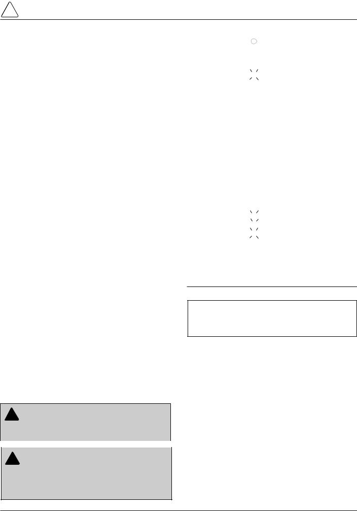
Screen 31 – Battery Monitor
The Battery Monitor displays the battery voltage, current, and voltage during a battery test. The Battery Monitor is used with the Battery Test pushbutton. Refer to the Battery Test Procedure section of these instructions for more information.
31 Battery Monitor |
|
Normal |
_______ V |
Normal |
_____ mA |
Test |
_______ V |
|
|
Screen 32 – Phase Minimum Trip Settings
Phase minimum trip settings are listed for the four protection profiles. Line 1 is the normal setting, ALT1 is profile No. 1, ALT2 is profile No. 2, and ALT3 is profile No. 3. Phase Minimum Trip Settings allow verification of trip settings before selection of an alternate profile.
32 – Phase MT |
______ A |
ALT1 MT |
______ A |
ALT2 MT |
______ A |
ALT3 MT |
______ A |
|
|
Screen 33 – Ground Minimum Trip Settings
Ground minimum trip settings are listed for the four protection profiles. Line 1 is the normal setting, ALT1 is profile No. 1, ALT2 is profile No. 2, and ALT3 is profile No. 3. Ground Minimum Trip Settings allow verification of trip settings before selection of an alternate profile.
33 Gnd MT |
______ A |
Alt1 MT |
_______A |
Alt2 MT |
______A |
Alt3 MT |
_______A |
|
|
Screen 34 – Ground Max, Phase 1-2 Max Demand
Currents
34 Gnd Max |
____________A |
Time |
Date |
Ph1-2 Max |
____________A |
Time |
Date |
|
|
Screen 35 – Phase 3-4 Max, Phase 5-6 Max Demand
Currents
35 Ph 3-4 Max |
____________A |
Time |
Date |
Ph5-6 Max |
____________A |
Time |
Date |
|
|
11
Kyle Form 5, Form 5 UDP, Form 5 DC NOVA Recloser Control Installation and Operation Instructions
Screen 36 – Ground Min, Phase 1-2 Min Demand
Currents
36 Gnd Min |
____________A |
Time |
Date |
Ph1-2 Min |
____________A |
Time |
Date |
|
|
Note: Demand currents are a time integrated value and do not reflect minimum or maximum instantaneous currents. The demand integration time constant is set via the interface software demand metering screen. These are the same values displayed in the histogram screen.
Screen 37 – Phase 3-4 Min, Phase 5-6 Min Currents
37 Ph3-4 Min |
____________A |
Time |
Date |
Ph5-6 Min |
____________A |
Time |
Date |
|
|
Note: Pressing and holding the RESET TARGETS/RESET MAX CURRENT key for three seconds will reset the minimum and maximum Demand values.
Screen 38 – Fault Location
38 Fault Location
Distance ____________miles
<Control Identification>
Time Date
Screen 39 – Control Information
39 CPU Firmware |
X.XX |
|
Firmware FW Database |
X |
|
|
<Control Identification> |
|
Time |
Date |
|
|
|
|
Screen 40 – Communication Port 2 Settings
This message displays the protocol settings (2179 or DNP3.0), baud rate, and address for Serial Port #2. Baud rate and address are set using the interface software, while protocol is set at the factory based on user’s specifications.
40 – Comm Port 2 |
______ |
Protocol |
_______ |
Speed |
_______ |
Address |
_______ |
|
|
Screen 41 – Communication Port 3 Settings
This message displays the protocol settings (2179 or DNP3.0), baud rate, and address for Serial Port #3. Baud rate and address are set using the interface software, while protocol is set at the factory based on user’s specifications.
41 – Comm Port 3 |
______ |
Protocol |
_______ |
Speed |
_______ |
Address |
_______ |
|
|
Operation/Indication Pushbuttons
Nine frequently used features are provided on the control operator panel (Figure 7).
Note: These features are activated from the keypad, control interface software or SCADA signal.
To initiate an operation from the operator panel, press the CHANGE/LAMP TEST key to enter the CHANGE mode. The operator has 10 seconds to select an operation and modify settings. If no changes are made, the control will return to its operational state prior to entering the CHANGE mode. This prevents accidental changing of settings.
Red LEDs located on each switch indicate the status of the function, regardless of local or remote activation. For example, if Cold Load Pickup was activated from a SCADA signal, the red indicator would illuminate even though it was not activated from the operator panel.
Note: Operation LEDs activated from local or remote sources do not illuminate when the front panel is in the powersave mode.
GND TRIP |
NON |
SUPERVISORY |
|
BLOCKED |
RECLOSING |
BLOCKED |
|
|
|
||
COLD LOAD |
BATTERY |
FAST |
|
PICKUP |
TEST |
TRIPS |
|
BLOCKED |
DISABLED |
||
|
|||
ALTERNATE |
ALTERNATE |
ALTERNATE |
|
PROFILE |
PROFILE |
PROFILE |
|
NO. 1 |
NO. 2 |
NO. 3 |
Figure 7.
Operation/indication pushbuttons.
GND TRIP BLOCKED
Ground Trip Blocked is activated by pressing the CHANGE/LAMP TEST key, then pressing the GND TRIP BLOCKED key. The red indicator illuminates.
12
!
SAFETY FOR LIFE
S280-79-10
NON RECLOSING
Non-reclosing mode disables any automatic reclosing operations. Non-reclosing does not alter the active TCC. The feature is activated by pressing the CHANGE/LAMP TEST key, then pressing the NON RECLOSING key. The red indicator illuminates.
SUPERVISORY BLOCKED
Supervisory Blocked disables supervisory SCADA and the interface software; remote SCADA remains active. Operational data and metering information are available while the control is in the SUPERVISORY BLOCKED position. The TRIP and CLOSE pushbuttons are active independently of the SUPERVISORY BLOCKED function.
Activation of the feature is restricted to the operator panel keypad by pressing the CHANGE/LAMP TEST key, then pressing the SUPERVISORY BLOCKED key.
COLD LOAD PICKUP BLOCKED
The Cold Load Pickup feature is blocked while the COLD LOAD PICKUP BLOCKED is active. When CLPU is not blocked, the control utilizes the Cold Load Pickup TCC, reclose interval, operations to lockout and minimum trip settings in lieu of the normal first operation protection settings.
Note: The Cold Load Pickup Blocked key is replaced by the SENSITIVE GROUND FAULT key on international controls.
BATTERY TEST
Depressing the BATTERY TEST key performs a control battery test. The red indicator illuminates and turns off automatically when the control has finished performing the test. Refer to the Battery Test Procedure section of these instructions for further details on testing the control battery.
FAST TRIPS DISABLED
Fast Trips Disabled commands the control to use the programmed Fast Trips Disabled time-current curve for all tripping operations.
ALTERNATE PROFILE Indicator/Key
The control has four separate protection profiles; a normal profile, and Alternate Profiles 1, 2, and 3. Each profile changes all protection parameters for the control. Except for the normal profile, each has an indication and selection key. During control operation, if the three alternate profile indicator lights are not illuminated, the normal profile is active.
To select an alternate profile, press the CHANGE/LAMP TEST key, then press the desired alternate profile. To return to the normal profile, simply turn off the active alternate profile. These functions can also be operated remotely via communications interfaces.
Note: Program all protection profiles. Program unused alternate profiles should be programmed with the same setting as one of the applicable profiles. Default settings on unused alternate profiles can cause unnecessary outages if they are below normal system requirements.
Note: The minimum trip values for each protection profile are shown on Screens 32 and 33 of the LCD display. Check these minimum trip values prior to changing an alternate profile to avoid misoperation of the control under load conditions.
Note: On Form 5 UDP controls, Alternate Profile 3 is replaced with SWITCH MODE.
HOT LINE TAG Switch
! |
WARNING: Hazardous voltage. Do not use Hot |
Line Tag as a substitute for a visible disconnect. |
Always establish a visible disconnect prior to performing any work requiring a de-energized line. Failure to comply may cause death, severe personal injury, or
equipment damage. |
T276.0 |
Hot Line Tag is provided for live-line work applications. All closing operations are disabled when the Hot Line Tag feature is activated. While active, the control utilizes an independent, user-selectable time-current curve for trip operations.
IMPORTANT: Hot Line Tag activation does not cause the recloser to trip open. It only prevents the recloser from closing.
IMPORTANT: Hot Line Tag is intended solely for live-line work applications, such as maintenance, repairs or improvements to the distribution system, that occur while the line remains energized.
The Hot Line Tag feature (Figure 8) consists of a toggle switch and an LED indicator which illuminates when the function is active. When active, Hot Line Tag prevents all closing attempts and shifts protection to one trip to lockout on the programmed time-current curve. The Hot Line Tag function takes precedence over Cold Load Pickup, Non Reclosing, and Fast Trips Disabled.
Activation is accomplished by placing the operator panel toggle switch to the ON position, or via SCADA command. Hot Line Tag is activated from the operator panel, communication Port 2, communication Port 3, or a Discrete Interface Module (DIF). All sources must be off to de-acti- vate Hot Line Tag.
The Hot Line Tag feature may only be reset by the source which initiates the function. For example, if Hot Line Tag is activated at the operator panel, resetting the function is only possible at the operator panel, and not via SCADA command. For SCADA, Hot Line Tag must be disabled via the same port number where Hot Line Tag was originally enabled.
HOT LINE
TAG
ON
OFF
Figure 8.
Hot Line Tag Switch.
13

Kyle Form 5, Form 5 UDP, Form 5 DC NOVA Recloser Control Installation and Operation Instructions
RS-232 Communication Port
The standard Form 5 control is equipped with a operator panel RS-232 port for interface with a personal computer running the Form 5 interface software program. This ninepin female data communication equipment (DCE) Port 1 permits the uploading of all programming information stored in the control, including protection profiles, event recorder, data profiles, alarms, counters, and metering information. Port 1 provides a simple means to download operating parameters from a personal computer to the control.The protocol, baud rate and address for Port 1 are identified from the LCD display.
If a fiber-optic or RS-232 accessory board is connected to Port 2 (located on the back of the operator panel) any external electrical connection from the operator panel will disable the accessory board.
Note: The operator panel RS-232 port is intended only for temporary connection of a personal computer. Permanent serial communications must be made via the RS232 or fiber-optic accessory board.
Battery Test Procedure
The condition of the control battery is tested by depressing the BATTERY TEST hot key on the operator panel. No external current/voltage meter is necessary for testing.
The control performs a self-test every 12 hours or when initiated by an external command. When a battery test is initiated, the spurious charge is first drained to allow the battery voltage to equalize. A 10-ohm, 55-watt resistor is then placed across the battery terminals and a voltage drop is calculated. If the drop from the equalized voltage to the test voltage exceeds 2 volts, then the CHECK BATTERY LED is illuminated.
To perform a battery test:
1.Using the Next and BACK keys, scroll through the LCD display to Screen 31, the Battery Monitor screen.
2.Record the NORMAL VOLTS and NORMAL CURRENT readings from the screen.
Note: Voltage should be between 25 to 31 volts with higher readings at colder temperatures. Under normal conditions with ac connected and the battery trickle charging, the current should read less than 20 mA. With ac connected and in bulk charging mode, current will range from 12 to 600 mA. With ac disconnected and the battery supplying the load, current will read -180 mA to -600mA depending on accessories connected.
3.Momentarily, press the CHANGE/LAMP TEST key, then BATTERY TEST key.
Note: AC power can be either connected or disconnected for Step 3.
4.Record the TEST VOLTS reading from the LCD and the status of the CHECK BATTERY LED. Service the battery if the CHECK BATTERY LED is illuminated.
Control Features
The Form 5 recloser control offers numerous standard features and accessories that allow the user the utmost flexibility in designing a control suitable for their application requirements.
Under/Over Frequency Loadshedding
The Form 5 control includes provisions for frequency loadshedding that trips the recloser for conditions of under or over system frequency. Access to this feature is through frequency threshold, trip time, and allowable voltage threshold.
With the auto-restoration feature, the Form 5 can be set to close the recloser after the system frequency and voltage have recovered. Parameters available for setting include frequency and voltage thresholds and time delay.
A frequency alarm is available and can be configured for notification.
Voltage Protection (120 Vac-based)
Voltage protection functionality is included as standard on all Form 5 controls. A recloser trip will be issued for under and over voltage conditions when the monitored voltage falls outside user-specified limits for a selectable time. Response mode includes any single-phase, all three phases, and single-phase with three-phase inhibit. Response mode facilitates protecting against a single phase condition common when a high side fuse operates on a distribution transformer. Parameters are also available to provide auto restoration after a trip. A voltage alarm is available and can be configured for notification.
Protection Profiles
Four separate protection profiles are included to allow the user to adapt overcurrent settings for varying system conditions such as load, live line work or weather. The active profile is selected from the operator panel or with the interface software or SCADA (Figure 9). Each profile has 14 TCC specifications plus reclose intervals, sequence coordination and reset times to maintain independent protection parameters.
Figure 9.
Interface software sample protection profile.
14
!
SAFETY
FOR LIFE
Power Metering
Power metering includes singleand three-phase Watts, VARS, KVARS, KWH measurements, and the per phase and total system Power Factor (PF).
Power Factor Sign Metering
This feature allows a user to configure the sign that is applied to the power factor. The user may select between the standard definition of power factor (cosine of angle between current and voltage) or the Cooper Power Systems default of the power factor sign following power flow.
Voltage Metering
Six voltages (3-source and 3-load) are metered as standard on the Form 5 control. The user selects either phase- to-phase or phase-to-ground values from the control operator panel, interface software, or serial communications. This reference is changed by selecting the voltage sensor correction in the “Hardware” setup portion of the interface software.
Fast Trips Disabled
Fast Trips Disabled provides the user a quick and efficient method for reducing momentary interruptions or “blinks”. When activated from the front keypad, programmed trips to lockout will time according to the selected time-current curve for Fast Trips Disabled. This curve is programmable for both phase and ground on each protection profile. A separate trips-to-lockout setting is also provided. See Figure 9.
Trip Failure Detection
The Trip Failure Detection feature is an internal diagnostic alarm for verifying the proper operation of circuit tripping and fault clearing of the recloser. Trip Failure detection indicates the recloser has failed to trip all phases following a trip signal from the control. Failure to trip is assumed if a current of at least 10 Amps is detected approximately 2 seconds after the trip signal is initiated.
Upon activation of the feature, these four LEDs flash 1 second on, 1 second off (Figure 10):
•RECLOSER MALFUNCTION
•RECLOSER CLOSED
•RECLOSER OPEN
•CONTROL LOCKOUT
! |
DANGER: Explosion. Stay clear of a recloser |
|
that is in a trip failure mode. A recloser in trip fail- |
||
|
ure mode may explode resulting in death or severe per-
|
sonal injury. |
T271.0 |
|
|
|
|
|
|
|
|
|
|
|
|
! |
WARNING: Hazardous voltage. This device is |
|
||
not a substitute for a visible disconnect. Follow all |
|
|||
|
|
|
||
locally approved safety practices. Failure to follow proper safety practices can result in contact with high voltage, which will cause death or severe personal
injury. |
G112.1 |
S280-79-10
AC POWER
 ABOVE MIN TRIP
 CHECK BATTERY
 RECLOSER MALFUNCTION
 REVERSE POWER FLOW
 BUSHINGS 1-2 FAULT TARGET
 BUSHINGS 3-4 FAULT TARGET
 BUSHINGS 5-6 FAULT TARGET
 GROUND FAULT TARGET
 SENSITIVE-GROUND FAULT TARGET
 BUSHINGS 1-2 VOLTAGE
 BUSHINGS 3-4 VOLTAGE
 BUSHINGS 5-6 VOLTAGE
 RECLOSER CLOSED
 RECLOSER OPEN
 CONTROL LOCKOUT
Figure 10.
RECLOSER MALFUNCTION, RECLOSER CLOSED, RECLOSER OPEN and CONTROL LOCKOUT LEDs will blink for the affected phase as indication of Trip Failure.
IMPORTANT: The recloser must be isolated and deenergized immediately upon detection of trip failure. Follow proper procedures and safety practices to isolate and de-energize the recloser.
The Trip Failure Detection alarm may be triggered from many potential sources including mechanical, electrical, control, or interrupter failure. Interrupter failure may include loss of vacuum in a vacuum interrupter.
To clear Trip Failure Alarm, depress and hold the RESET TARGETS/RESET MAX CURRENTS keypad for 3 seconds. This also resets targets and demand currents.
Note: There is no remote reset available with the trip failure detection feature. It cannot be remotely turned off.
When the trip failure alarm is activated, an event is recorded and a status alarm activated (if enabled) and preserved during system resets.
To test the Trip Failure Detection feature, see Testing With Type MET Tester in the TESTING AND TROUBLESHOOTING section of this manual.
15
Kyle Form 5, Form 5 UDP, Form 5 DC NOVA Recloser Control Installation and Operation Instructions
Manual Close Delay
Manual Close Delay provides a delay from the time that the manual CLOSE button is pushed to the time the manual close operation is performed.
The delay is programmable from 0 to 60 seconds in 1 second increments. A programmed delay value can be overridden for immediate closing by pressing the CLOSE button a second time.
An active Manual Close Delay can be canceled by pressing the TRIP/LOCKOUT button.
The default setting has the feature disabled (0 seconds). The RECLOSER CLOSED LED indicates the status of the feature. See Figure 11.
 RECLOSER CLOSED
 RECLOSER OPEN
 CONTROL LOCKOUT
Figure 11.
The blinking of the RECLOSER CLOSED LED indicates Manual Close Delay is active.
Harmonic Analysis
Extensive harmonic analysis is performed by the Form 5 control for both currents and voltages. Analysis is performed on-line (updates every 30 seconds) or demand integrated to user-specified time values. The Total Harmonic Distortion (THD) for current and voltage is available from the operator panel display (Figure 12) while complete analysis, including graphing capabilities, is provided from the Form 5 interface software.
Pg14 Gnd |
%THDI |
|
Ph1-2 |
%THDI |
|
Ph3-4 |
%THDI |
|
Ph5-6 |
%THDI |
|
NEXT |
BACK |
|
RESET |
CHANGE |
|
TARGETS |
||
|
||
RESET |
LAMP |
|
MAX CURRENT |
TEST |
Figure 12.
Form 5 operator panel harmonic readout.
Reverse Power Flow
Feeder load monitoring is enhanced with the inclusion of the power flow monitoring feature. When power flow from the load to the source side of the recloser is detected, the control illuminates an operator-panel indicator. Response time to a reverse power condition is one second. An alarm is also available for remote interrogation.
Note: Voltage sensor polarity must be correct for reverse power flow to function properly.
Event Recorder
The Event Recorder maintains a log of operating events for later readout and analysis by the user. Approximately 500 events can be stored in non-volatile memory. For each event type, time of occurrence, and other relevant information is stored. When the event recorder has reached is capacity, the oldest event is deleted as a new event is added.
Histograms
Demand metered voltages and currents can be reported using the histogram tool. It displays the number of occurrences of a variable versus its value in between userdefined minimum and maximum limits. Date and time are recorded for the maximum and minimum demand values.
Data Profiler
A fully configurable data profiler is available which allows the user to collect information by sampling demand data at selectable intervals. These time-stamped values can then be plotted to determine weekly load profiles, daily harmonic disturbances or hourly voltage fluctuations. The data profiler can provide more than 200 days of information, depending upon configuration parameters.
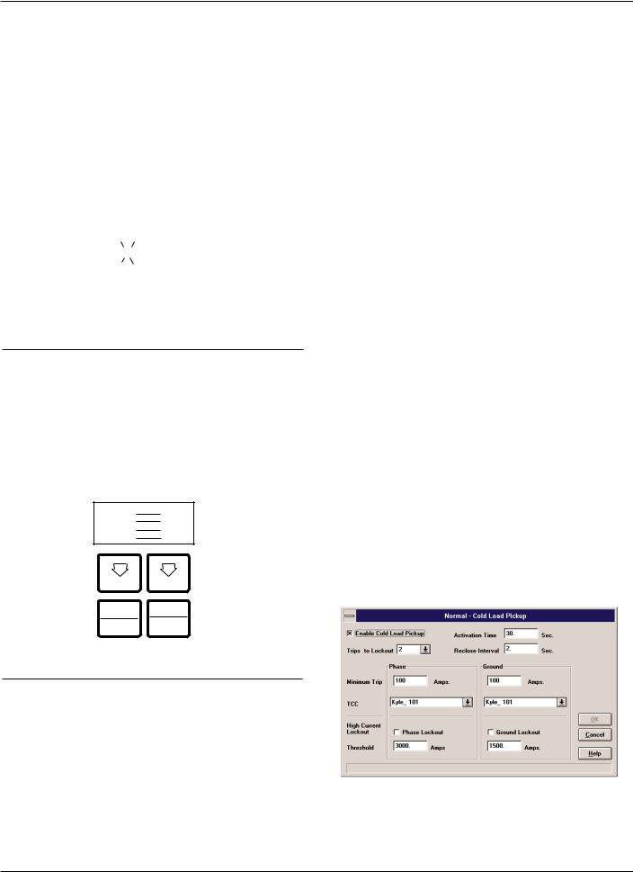
Cold Load Pickup
Cold Load Pickup (CLPU) must be enabled through the interface software (Figure 13) before it can be activated remotely or from the CLOSE pushbutton on the operator panel. The CLPU feature provides the user with the ability to alter protection for abnormal system conditions. It is active for a programmable time interval which begins with each manual close. Once this time elapses, protection reverts back to the programmed sequence. Use the Form 5 control interface software to program the activation time and time-current characteristics applicable to Cold-Load Pickup.
Note: When CLPU is active, the control utilizes the Cold Load Pickup TCC, reclose interval, operations to lockout, and minimum trip settings in lieu of the normal protection settings.
Figure 13.
Interface software Cold Load Pickup settings.
16

!
SAFETY
FOR LIFE
Alarms
Status and data alarms are available for many control parameters such as voltage, currents, thresholds. Data alarm function compares metered data to user-pro- grammed alarm high and low limits and issues an alarm of user-specified priority if limits are exceeded. The status alarm function monitors status and issues an alarm of user-defined priority when the user programmed alarm conditions are met. The alarms are reported via communication ports and can be configured to trigger a data profile and event record. Alarms do not affect the protection functions of the control.
Fault Location
Fault Location provides an approximate distance of a fault from the the Form 5 Control The distance is based on the current fault magnitude, the type of fault, and system parameters entered by the user. The LCD display (Screen 38) identifies the estimated distance in miles or kilometers (km) from the control.
The fault location algorithm performs an impedance calculation based on:
•Single-phase to ground fault
•Phase-to-phase fault
•Double-line to ground fault
•Three-phase fault
This information is recorded as an event in the control Event Recorder for retrieval. The fault location algorithm does not require voltage sensing. If the location cannot be determined, no event is recorded and dashes are displayed on the LCD screen.
Setting the parameters for Fault Location is done through the interface software. The user enters line impedance parameters and system voltage information into the software via the Protection Profile menu. See Figure 14.
S280-79-10
Figure 14.
Fault Location configuration screen.
The following system parameters must be entered via the Protection Profile menu for each profile:
•Nominal system line-to-line voltage
Note: If the Fault Location feature is not desired, the nominal system voltage parameter should be set at 1.
•Source-side zero sequence and positive sequence impedance. This includes impedance up to the location of the Form 5 control.
•Line-side zero sequence and positive sequence impedance per mile or km.
•The distance units of the line impedance in miles or km.
IMPORTANT: Fault Location is not a protection function. Its purpose is to define a fault and provide its approximate location relative to the Form 5 control detecting the fault.
Refer to Service Information S280-79-2 Form 5 Micropro- cessor-Based Recloser Control Programming Guide for additional information.
17
 Loading...