


OPERATOR’S GUIDE
|
|
|
|
LEAD SIZE |
HR |
LEAD |
|
CHARGE 2 |
ANALYZE |
|
CO2 31mm Hg |
Sp02 % |
ECG |
|
x1.5 72 |
|
|||||
|
|
|
3 |
|
||||||
17RR |
|
100 |
|
PADS |
|
SIZE |
|
SHOCK |
||
|
|
|
|
|
|
|
|
|
|
|
|
|
|
|
|
|
|
|
|
ENERGY |
|
|
|
|
|
|
|
|
ALARM |
|
SELECT |
|
|
|
|
|
|
|
|
|
|
|
|
|
|
|
|
|
|
|
SUSPEND |
|
|
|
ECG |
|
|
|
|
|
|
|
|
|
|
|
|
|
|
|
|
|
RECORDER MONITOR |
|
1DEFIB |
|
CO2 |
|
|
|
|
|
|
OFF |
|
|
|
|
|
|
|
|
|
|
|
|
|
|
|
|
|
|
|
|
|
PACER |
|
|
|
Param |
Wave 2 |
ID# |
|
Alarms |
12 Lead |
PACER |
|
|
PACER |
|
|
OUTPUT |
|
|
|||||||
|
4:1 |
|
RATE |
|||||||
|
|
|
|
|
|
|
mA |
|
||
|
|
|
|
|
|
|
|
|
ppm |
|
|
|
|
SUMMARY |
CODE |
|
|
|
|
||
|
|
CHARGER ON |
MARKER |
|
|
|
|
|||
|
|
|
|
|
|
|
|
|||
|
|
|
|
|
|
|
|
|
|
|
|
|
RELEASE |
|
|
|
|
|
|
|
|
October 2010 |
9650-0200-01 Rev YH |
An issue or revision date for this manual is shown on the front cover.
If more than three years have elapsed since this date, contact ZOLL Medical Corporation to determine if additional product information updates are available.
ZOLL, M Series, CPR-D•padz, and stat•padz are registered trademarks of ZOLL Medical Corporation. ZOLL Data Control Software, and Real CPR Help are trademarks of ZOLL Medical Corporation. 12SL and Catalyst MUSE are trademarks of GE Medical Systems.
Copyright © 2010 by ZOLL Medical Corporation. All rights reserved.
Table of Contents |
|
Section 1 General Information |
|
Product Description ............................................................................................................ |
1-1 |
How to Use This Manual..................................................................................................... |
1-2 |
Manual Updates.................................................................................................................. |
1-2 |
Unpacking........................................................................................................................... |
1-2 |
Accessories ........................................................................................................................ |
1-2 |
Symbols Used on the Equipment ....................................................................................... |
1-3 |
Defibrillator Function........................................................................................................... |
1-4 |
Intended Use — Manual Operation ............................................................................ |
1-4 |
Intended Use — Semiautomatic Operation (AED) ..................................................... |
1-4 |
Intended Use — CPR Monitoring ............................................................................... |
1-4 |
Semiautomatic Operation Contraindications for Use .................................................. |
1-4 |
Defibrillator Complications .......................................................................................... |
1-4 |
Defibrillator Output Energy ......................................................................................... |
1-4 |
External Pacemaker (Pacer Version Only) ......................................................................... |
1-5 |
Intended Use — Pacemaker ....................................................................................... |
1-5 |
Pacemaker Complications .......................................................................................... |
1-5 |
Pediatric Pacing .......................................................................................................... |
1-6 |
Monitor................................................................................................................................ |
1-6 |
Recorder Function .............................................................................................................. |
1-6 |
Paddle — Electrode Options .............................................................................................. |
1-6 |
Batteries.............................................................................................................................. |
1-6 |
Internal Battery Charger ..................................................................................................... |
1-6 |
External Battery Charger .................................................................................................... |
1-7 |
Diagnostics ......................................................................................................................... |
1-7 |
Safety Considerations......................................................................................................... |
1-8 |
WARNINGS ................................................................................................................ |
1-8 |
CAUTIONS ............................................................................................................... |
1-10 |
Restarting the Device........................................................................................................ |
1-10 |
FDA Regulations............................................................................................................... |
1-11 |
Tracking Requirements ............................................................................................. |
1-11 |
Notification of Adverse Events .................................................................................. |
1-11 |
Warranty (U.S. Only)......................................................................................................... |
1-11 |
Software License .............................................................................................................. |
1-12 |
Service.............................................................................................................................. |
1-12 |
U.S.A. Customers ..................................................................................................... |
1-12 |
International Customers ............................................................................................ |
1-12 |
Defibrillator Waveform Information ................................................................................... |
1-13 |
ECG Analysis Algorithm Accuracy.................................................................................... |
1-14 |
Clinical Performance Results .................................................................................... |
1-14 |
i
Section 2 Operating Controls and Indicators
Code Markers ..................................................................................................................... |
2-3 |
Summary Report................................................................................................................. |
2-4 |
Summary Report Formats .......................................................................................... |
2-4 |
Defibrillation Format .................................................................................................... |
2-4 |
Pacer Format (Pacer version only) ............................................................................. |
2-5 |
Heart Rate Alarm Activated Format ............................................................................ |
2-5 |
VF Alarm Activated (Refer to Section 8) ..................................................................... |
2-5 |
Recorder On Format ................................................................................................... |
2-5 |
Analyze Format ........................................................................................................... |
2-6 |
Manual Mode Activated .............................................................................................. |
2-6 |
Printing a Report................................................................................................................. |
2-7 |
Printing Part of a Report ..................................................................................................... |
2-7 |
Adding Patient Name and ID# to a Report ......................................................................... |
2-7 |
Printing an Incident Log ...................................................................................................... |
2-7 |
Erasing Summary Report Memory ..................................................................................... |
2-8 |
Section 3 Manual Defibrillation |
|
Emergency Defibrillation Procedure with Paddles.............................................................. |
3-1 |
Emergency Defibrillation Procedure with MFE Pads .......................................................... |
3-4 |
Open Chest Defibrillation with Internal Handles and Electrodes ........................................ |
3-6 |
Troubleshooting .................................................................................................................. |
3-6 |
Section 4 Advisory Defibrillation |
|
Advisory Defibrillation ......................................................................................................... |
4-1 |
Advisory Function Messages.............................................................................................. |
4-3 |
Warning Messages ............................................................................................................. |
4-3 |
Troubleshooting .................................................................................................................. |
4-4 |
Section 5 Automated External Defibrillator (AED) Operation |
|
Introduction ......................................................................................................................... |
5-1 |
AED Semi-Automatic Operation ......................................................................................... |
5-1 |
Operating Messages ................................................................................................... |
5-3 |
AED Manual Mode Operation............................................................................................. |
5-5 |
AED Voice Prompts .................................................................................................... |
5-5 |
Troubleshooting .................................................................................................................. |
5-5 |
Section 6 Synchronized Cardioversion |
|
General Information ............................................................................................................ |
6-1 |
Synchronized Cardioversion............................................................................................... |
6-1 |
Troubleshooting .................................................................................................................. |
6-3 |
Section 7 CPR Assistance
Prepare the Patient and Attach the CPRD-to-MFC Connector........................................... |
7-1 |
CPR Assist Display............................................................................................................. |
7-1 |
ii
CPR Compressions Indicator ............................................................................................. |
7-2 |
CPR Idle Time Display........................................................................................................ |
7-2 |
CPR Metronome ................................................................................................................. |
7-2 |
Section 8 Non-Invasive Temporary Pacing (Pacer Version Only)
Non-invasive Temporary Pacing ......................................................................................... |
8-1 |
Special Pacing Applications................................................................................................ |
8-3 |
Standby Pacing ........................................................................................................... |
8-3 |
Asynchronous Pacing ................................................................................................. |
8-4 |
Pediatric Pacing .......................................................................................................... |
8-4 |
Troubleshooting .................................................................................................................. |
8-4 |
Section 9 |
ECG Monitoring |
|
Introduction ......................................................................................................................... |
9-1 |
|
Preparations........................................................................................................................ |
9-1 |
|
Electrode Placement ................................................................................................... |
9-1 |
|
Attach Monitoring Electrodes ...................................................................................... |
9-2 |
|
Troubleshooting .................................................................................................................. |
9-2 |
|
Set the Controls .................................................................................................................. |
9-2 |
|
Spikes from Implantable Pacemakers................................................................................. |
9-2 |
|
Alarms |
................................................................................................................................. |
9-3 |
Setting Alarm Limits .................................................................................................... |
9-3 |
|
Alarm ............................................................................................................Function |
9-3 |
|
Alarm ................................................................................................................Limits |
9-3 |
|
Suspending ..............................................................................and Silencing Alarms |
9-3 |
|
Smart ..............................................................................................................Alarms |
9-4 |
|
Recorder ............................................................................................................Operation |
9-4 |
|
Diagnostic .................................................................................................Bandwidth |
9-4 |
|
5 Lead ...............................................................................................................Monitoring |
9-4 |
|
Simultaneous .............................................................3 Lead Printing (If Configured) |
9-5 |
|
Changing ......................................................from 5 Lead to 3 Lead ECG Monitoring |
9-5 |
|
Vital Signs ............................................................................................................Trending |
9-5 |
|
Viewing ......................................................Vital Signs Trending Data on the Display |
9-5 |
|
Printing ............................................................................a Vital Signs Trend Report |
9-6 |
|
NIBP ................................................................................................Trend Operation |
9-6 |
|
Clearing ............................................................................Vital Signs Trend Records |
9-6 |
|
Section 10 General Maintenance |
|
|
Periodic ................................................................................................................Testing |
10-1 |
|
Inspection ................................................................................................................. |
10-1 |
|
Cleaning .................................................................................................................... |
10-1 |
|
Cleaning .............................................................................the Recorder Printhead |
10-1 |
|
Semi-Automatic .................................................................................Defibrillator Testing |
10-2 |
|
1. ................................................................................Power-Up Sequence Check |
10-2 |
|
2. ................................................................................................... |
Defibrillator Test |
10-2 |
3. ............................................................................ |
Recorder Check (if applicable) |
10-2 |
iii
Manual Defibrillator Testing .............................................................................................. |
10-2 |
|
1. |
Power-Up Sequence Check ................................................................................. |
10-2 |
2. |
Delivered Energy and Shock Buttons ................................................................... |
10-2 |
3. |
Energy Delivery Test (Paddles/MFE Pads) .......................................................... |
10-3 |
4. |
Pacer Operation (Pacer Version Only) ................................................................. |
10-3 |
5. |
Recorder Check .................................................................................................... |
10-3 |
Changing Paper................................................................................................................ |
10-4 |
|
Setting Time and Date ...................................................................................................... |
10-4 |
|
Manual Method ......................................................................................................... |
10-4 |
|
Automated Method ................................................................................................... |
10-4 |
|
Operator’s Shift Checklist for M Series Products (Manual).............................................. |
10-6 |
|
Operator’s Shift Checklist for M Series Products (Semi-Automatic) ................................ |
10-7 |
|
Section 11 Battery Management |
|
Battery Care...................................................................................................................... |
11-1 |
Battery Life Expectancy ............................................................................................ |
11-1 |
Low Battery Message ............................................................................................... |
11-1 |
Changing the Battery Pack ....................................................................................... |
11-1 |
Charging and Testing Battery Packs ........................................................................ |
11-2 |
Achieving Optimal Battery Pack Performance.................................................................. |
11-2 |
Appendix A Specifications |
|
General ............................................................................................................................... |
A-1 |
Pacemaker (Pacer Version Only) ....................................................................................... |
A-2 |
ECG Monitoring .................................................................................................................. |
A-3 |
CPR Monitoring .................................................................................................................. |
A-3 |
Display ................................................................................................................................ |
A-3 |
Recorder ............................................................................................................................. |
A-4 |
PCMCIA Card ..................................................................................................................... |
A-4 |
Battery Packs...................................................................................................................... |
A-4 |
Guidance and Manufacturer’s Declaration — Electromagnetic Emissions......................... |
A-5 |
Electromagnetic Immunity Declaration (EID)...................................................................... |
A-6 |
EID for Life-Support Functions ........................................................................................... |
A-7 |
Recommended Separation Distances from RF Equipment for the M Series Life-Support |
|
Functions.......................................................................................................................... |
A-8 |
EID for Non–Life-Support Functions................................................................................... |
A-9 |
Recommended Separation Distances from RF Equipment for the M Series |
|
Non–Life-Support Functions........................................................................................... |
A-10 |
Appendix B Troubleshooting Guides
General ............................................................................................................................... |
B-1 |
Monitor ........................................................................................................................ |
B-1 |
Recorder ..................................................................................................................... |
B-3 |
Pacer (Pacer Version Only) ........................................................................................ |
B-4 |
Defibrillator .................................................................................................................. |
B-5 |
AC Charger ................................................................................................................. |
B-6 |
iv
Appendix C Medical Report Capability
PCMCIA Data Card............................................................................................................. |
C-1 |
Installing the PCMCIA Data Card ....................................................................................... |
C-1 |
Erasing A Memory Card ..................................................................................................... |
C-1 |
Warning Messages ............................................................................................................. |
C-2 |
Transferring Data to a PC with a PCMCIA Data Card Reader............................................ |
C-2 |
Uploading Data to a PC via Serial Link............................................................................... |
C-2 |
Troubleshooting .................................................................................................................. |
C-3 |
Display Messages............................................................................................................... |
C-4 |
v
vi
SECTION 1
GENERAL INFORMATION
NOTE: Your M Series may or may not contain all the features listed in this manual, depending on your particular configuration.
Product Description
The ZOLL® M Series® products combine a defibrillator, ECG display, advanced monitoring capabilities, and Noninvasive Transcutaneous Pacing (NTP) with communication, data printing and recording capabilities in a single lightweight portable instrument. The unit has been designed for all resuscitation situations and its small, compact, lightweight design makes it ideal for accompanying patients during transport. The product is powered by AC or DC mains and an easily replaced battery pack that is quickly recharged in the device when it is connected to AC or DC mains. In addition, the unit’s batteries may be recharged and tested using ZOLL PowerCharger systems designed for standard interchangeable ZOLL battery packs.
The product is designed for use in both the hospital and the rugged EMS environment. All of its ruggedized features add to its durability in hospital applications. The device is a versatile automated external defibrillator with or without manual capabilities and may be configured to operate in manual, advisory or semi-automated modes. Semi-automated versions of the device have a distinctive front panel with a single “ON” position. Conventional hospital style devices, which can be configured for manual, advisory or semi-automated operation, have a standardized ZOLL operator interface. When operating in the manual configuration the device operates as a conventional defibrillator where the device’s charging and discharging is fully controlled by the operator. In advisory and semi-automatic modes, some features of the device are automated and a sophisticated detection algorithm is used to identify ventricular fibrillation and determine the appropriateness of defibrillator shock delivery. Units may be configured to automatically charge, analyze, recharge, and prompt the operator to “PRESS SHOCK,” depending on local protocols. The unit is switched from the semi-automated mode to manual mode for ACLS use by pressing the appropriate soft key on the front panel.
The M Series assists caregivers during cardiopulminary resuscitation (CPR) by evaluating the rate and depth of chest compressions, and providing feedback to the rescuer. Real CPR Help™ requires the use of CPR-D•padz and the CPRD-to-MFC connector. Real CPR Help is available in the M Series unit with software version 38.90 or higher.
Information regarding the unit’s operation, patient ECG, and other physiological waveforms are displayed on a large 5.66 inch diagonal display which provides high contrast and visibility under virtually all lighting conditions. Operating and warning messages are displayed on the monitor and the unit can also be configured with voice prompts to alert the user to unit status. Self-diagnostic tests are performed when the instrument is turned on and the unit is periodically tested during operation.
A sophisticated data collection system, an optional internal summary report feature with printer, and PCMCIA cards are available for this unit. A PCMCIA card can be installed in the unit to record ECG and virtually all device data when the device is turned on. In addition, voice data from any incident around this device can also be recorded. The data stored on the PCMCIA card can be reviewed and archived on a properly equipped personal computer using ZOLL Data Control™ software.
An annotating stripchart recorder can be included to provide immediate documentation as well as summary report functions about patient care and treatment during use.
Some M Series products are intended for use in the semiautomatic mode by first responders and emergency medical technicians certified by an appropriate federal, state or local government authority. Some M Series products are intended for use in manual mode by personnel certified by appropriate federal, state or local authority to provide advanced life support care.
1-1

M SERIES OPERATOR’S GUIDE
Some M Series products are intended for use in the pre-hospital emergency medical care setting, indoors and outdoors, including first response vehicles, fire vehicles, basic and advanced level ambulances as well as by both Basic Life Support (BLS) and Advanced Cardiac Life Support (ACLS) staff in hospitals under protocol control.
How to Use This Manual
The M Series Operator's Guide provides information operators need for the safe and effective use and care of the
M Series products. It is important that all persons using this device read and understand all the information contained within.
This manual is organized for manual mode operators, advisory mode operators and semiautomatic mode operators. If you will only use the device in manual mode or advisory mode you do not need to read Section 5. If you will only use the device in semi-automatic mode you do not need to read Sections 3, 4, or 6.
Please read thoroughly the safety considerations and warnings section. Procedures for daily checkout and unit care are found in the Maintenance Section.
This manual is supplemented by manual inserts for options available on the M Series. These inserts contain additional warnings, precautions, and safety-related information.
Manual Updates
ZOLL Medical Corporation provides Manual Updates to inform customers of changes in device information and use. The updates are mailed to each registered M Series purchaser automatically. All users should carefully review each manual update to understand its significance and then file it in its appropriate section within this manual for subsequent reference.
Unpacking
Carefully inspect each container for damage. If the shipping container or cushion material is damaged, it should be kept until the contents have been checked for completeness and the instrument has been checked for mechanical and electrical integrity. If the contents are incomplete, if there is mechanical damage, or if the instrument does not pass its electrical self-test, U.S.A. customers should call ZOLL Medical Corporation (1-800-348-9011). International customers should contact the nearest ZOLL authorized representative. If the shipping container is damaged, also notify the carrier.
Accessories
Note: The terms “ZOLL Multi-Function Electrode (MFE) Pads” and “MFE Pads” are used interchangeably throughout this manual.
•Service Manual
•Internal Defibrillator Handles and Cable Assembly *
•Internal Defibrillator Electrodes: 3.0" (7.6 cm), 2.7" (6.8 cm), 2.0" (5.1 cm), 1.6" (4.0 cm), & 1.0" (2.5 cm) diameter.*
•Adult, Multi-Function pacing/defibrillation electrode pads (12 pair/box)
•Pediatric, Multi-Function pacing/ defibrillation electrode pads (6 pair/box)
•Adult Multi-Function pacing/defibrillation stat•padz®
•Multi-Function Cable assembly for use with Multi-Function pacing/defibrillation Electrode Pads*
•CPR-D•padz®
•CPR stat•padz
•CPRD-to-MFC connector
•Base PowerCharger4x4
•Base PowerCharger1x1
•ECG Simulator
•Battery Management Program Manual
•Replacement battery packs*
•Smart Batteries
•AAMI Standard 3-lead ECG patient cable & 5-lead ECG patient cable
•IEC Standard 3-lead ECG patient cable & 5-lead ECG patient cable
•Carry Case
1-2
General Information
* These accessories are considered safety-relevant components
Symbols Used on the Equipment
Any or all of the following symbols may be used in this manual or on this equipment:
Type B patient connection
Type BF patient connection
Type CF patient connection
Defibrillation protected Type BF patient connection
Defibrillation protected Type CF patient connection
Attention Refer to manual for more information
Fusible Link
Protective (earth) ground terminal
DANGER High Voltage present
Alternating current
1-3

M SERIES OPERATOR’S GUIDE
Defibrillator Function
The M Series products contain a DC defibrillator capable of delivering up to 360 joules of energy. It may be used in synchronized mode to perform synchronized cardioversion by using the R-wave of the patient’s ECG as a timing reference. The unit uses paddles or disposable, pre-gelled, MFE Pads for defibrillation.
Intended Use — Manual Operation
Use of the M Series products in the manual mode for defibrillation is indicated on victims of cardiac arrest where there is apparent lack of circulation as indicated by:
•Unconsciousness
•Absence of breathing
•Absence of pulse.
This product should be used only by qualified medical personnel for converting ventricular fibrillation and rapid ventricular tachycardia to sinus rhythm or other cardiac rhythms capable of producing hemodynamically significant heart beats.
Intended Use — Semiautomatic Operation (AED)
The M Series products are designed for use by emergency care personnel who have completed training and certification requirements applicable to the use of a defibrillator where the device operator controls delivery of shocks to the patient.
They are specifically designed for use in early defibrillation programs where the delivery of a defibrillator shock during resuscitation involving CPR, transportation, and definitive care are incorporated into a medically-approved patient care protocol.
The M Series products must be prescribed for use by a physician or medical advisor of an emergency response team.
Use of the device in the Semiautomatic mode for defibrillation is indicated on victims of cardiac arrest where there is apparent lack of circulation as indicated by:
•Unconsciousness
•Absence of breathing
•Absence of pulse.
Specifications for the ECG rhythm analysis function are provided at the end of this section.
Intended Use — CPR Monitoring
The CPR monitoring function provides visual and audio feedback designed to encourage rescuers to perform chest compressions at the AHA/ERC recommended rate of 100 compressions per minute. Visual prompts encourage a compression depth of 1.5 to 2 inches (3.8 to 5.0 cm) for adult patients.
The CPR monitoring function is not intended for use on patients under 8 years of age.
Semiautomatic Operation Contraindications for Use
The rhythm analysis function may not reliably identify ventricular fibrillation in the presence of an implantable pacemaker. Inspection of the electrocardiogram and clinical evidence of cardiopulmonary arrest should be the basis for any treatment of patients with implantable pacemakers.
Do not use the rhythm analysis function during patient movement on a stretcher or in an ambulance or other conveyance. A patient must be motionless during ECG analysis. Do not touch the patient during analysis. Cease all movement via stretcher or vehicle prior to analyzing the ECG. If using the device in an emergency vehicle, bring the vehicle to a halt before activating the analysis function.
Note: Do not use the unit’s AED function on patients under 8 years of age.
Defibrillator Complications
Inappropriate defibrillation or cardioversion of a patient (e.g., with no malignant arrhythmia) may precipitate ventricular fibrillation, asystole, or other dangerous arrhythmias.
Defibrillation without proper application of electrode pads or paddle electrolyte gel may be ineffective and cause burns, particularly when repeated shocks are necessary. Erythema or hyperemia of the skin under the paddles or MFE Pads often occurs; this effect is usually enhanced along the perimeter of the paddle or electrode. This reddening should substantially lessen within 72 hours.
Defibrillator Output Energy
The M Series products may deliver up to 360 joules into a 50 ohm impedance. The energy delivered through the chest wall, however, is determined by the patient’s transthoracic impedance. An adequate amount of electrolyte gel must be applied to the paddles and a force of 10-12 kilograms must be applied to each paddle in order to minimize this impedance. If MFE Pads are used, make sure that they are properly applied. (Refer to the instructions on the Multi-Function Electrode package).
1-4

General Information
External Pacemaker (Pacer Version Only)
Non-invasive Transcutaneous Pacing (NTP) is an established and proven technique. This therapy is easily and rapidly applied in both emergency and nonemergency situations when temporary cardiac stimulation is indicated.
Some M Series products may contain an optional demand pacemaker consisting of a pulse generator and ECG sensing circuitry. The output current of the pacemaker is continuously variable from 0 to 140 mA and the rate is continuously variable from 30 to 180 pulses per minute (ppm).
The pacing output pulse is delivered to the heart by specially designed ZOLL MFE Pads placed on the back and the precordium.
The characteristics of the output pulse, together with the design and placement of the electrodes, minimize cutaneous nerve stimulation, cardiac stimulation threshold currents, and reduce discomfort due to skeletal muscle contraction.
The unique design of the M Series products allow clear viewing and interpretation of the electrocardiogram (ECG) on the display without offset or distortion during external pacing.
Proper operation of the device, together with correct electrode placement, is critical to obtaining optimal results. Every operator must be thoroughly familiar with these operating instructions.
Intended Use — Pacemaker
This product may be used for temporary external cardiac pacing in conscious or unconscious patients as an alternative to endocardial stimulation.
Note: This device must not be connected to internal pacemaker electrodes.
The purposes of pacing include:
Resuscitation from standstill or bradycardia of any etiology:
Noninvasive pacing has been used for resuscitation from cardiac standstill, reflex vagal standstill, drug induced standstill (due to procainamide, quinidine, digitalis, b- blockers, verapamil, etc.) and unexpected circulatory arrest (due to anesthesia, surgery, angiography, and other therapeutic or diagnostic procedures). It has also been used for temporary acceleration of bradycardia in Stokes-Adams disease and sick-sinus syndrome. It is safer, more reliable, and more rapidly applied in an emergency than endocardial or other temporary electrodes.
As a standby when standstill or bradycardia might be expected:
Noninvasive pacing may be useful as a standby when cardiac arrest or symptomatic bradycardia might be expected due to acute myocardial infarction, drug toxicity, anesthesia or surgery. It is also useful as a temporary treatment in patients awaiting pacemaker implants or the introduction of transvenous therapy. In standby pacing applications, noninvasive pacing may provide an alternative to transvenous therapy that avoids the risks of displacement, infection, hemorrhage, embolization, perforation, phlebitis and mechanical or electrical stimulation of ventricular tachycardia or fibrillation associated with endocardial pacing.
Suppression of tachycardia:
Increased heart rates in response to external pacing often suppress ventricular ectopic activity and may prevent tachycardia.
Pacemaker Complications
Ventricular fibrillation will not respond to pacing and requires immediate defibrillation. The patient’s dysrhythmia must therefore be determined immediately, so that appropriate therapy can be employed. If the patient is in ventricular fibrillation and defibrillation is successful, but cardiac standstill (asystole) ensues, the pacemaker should be used.
Ventricular or supraventricular tachycardias may be interrupted with pacing but in an emergency or during circulatory collapse, synchronized cardioversion is faster and more certain. (See Synchronized Cardioversion Section.)
Electromechanical dissociation may occur following prolonged cardiac arrest or in other disease states with myocardial depression. Pacing may then produce ECG responses without effective mechanical contractions, and other treatment is required.
Pacing may evoke undesirable repetitive responses, tachycardia, or fibrillation in the presence of generalized hypoxia, myocardial ischemia, cardiac drug toxicity, electrolyte imbalance, or other cardiac diseases.
Pacing by any method tends to inhibit intrinsic rhythmicity. Abrupt cessation of pacing, particularly at rapid rates, can cause ventricular standstill and should be avoided.
Noninvasive Temporary Pacing may cause discomfort of varying intensity, which occasionally can be severe and preclude its continued use in conscious patients.
Similarly, unavoidable skeletal muscle contraction may be troublesome in very sick patients and may limit continuous use to a few hours. Erythema or hyperemia of the skin under the MFE Pads often occurs; this effect is usually enhanced along the perimeter of the electrode.
1-5

M SERIES OPERATOR’S GUIDE
This reddening should substantially lessen within 72 hours.
There have been reports of burns under the anterior electrode when pacing adult patients with severely restricted blood flow to the skin. Prolonged pacing should be avoided in these cases and periodic inspection of the skin is advised.
There are reports of transient inhibition of spontaneous respiration in unconscious patients with previously available units when the anterior electrode was placed too low on the abdomen.
This device must not be connected to internal pacemaker electrodes.
Pediatric Pacing
Pacing can be performed on pediatric patients weighing 33lbs / 15kg or less using special ZOLL pediatric MFE Pads. Prolonged pacing (in excess of 30 minutes), particularly in neonates, could cause burns. Periodic inspection of the underlying skin is recommended.
Monitor
The patient’s ECG is monitored by connecting the patient to the unit via the 3 or 5 lead patient cable, MFE Pads, or through the paddles. Four seconds of ECG is presented on the display along with the following information:
•averaged heart rate, derived from measuring R to R intervals
•lead selections - I, II, III, aVR, aVL, aVF, V (with ECG cable), PADDLES, or PADS
•ECG size - 0.5, 1, 1.5, 2, 3 cm/mV
•pacemaker output in milliamps (Pacer version only)
•pacemaker stimulus rate in pulses per minute (Pacer versions only)
•defibrillator output in joules
•other operational prompts, messages, and diagnostic codes
Monitoring or diagnostic ECG bandwidth is selectable.
Recorder Function
A strip recorder is provided to document events. The strip recorder normally operates in the delay mode (6 seconds) to insure capture of critical ECG information.
The recorder may be activated manually by pressing the RECORDER button. It will be activated automatically whenever a defibrillation SHOCK is delivered, a heart rate alarm occurs, or the rhythm analysis function is activated. The strip recorder may also be configured not to print during these events.
Paddle — Electrode Options
The M Series products will defibrillate, cardiovert and monitor ECG using either defibrillation paddles or ZOLL Multi-Function Electrode (MFE) Pads.
The pacer version of the M Series will also pace using ZOLL MFE Pads.
Energy Select, Charge, and Shock controls are located on the paddles and front panel. When using MFE Pads, the controls on the front panel of the unit must be used. To switch between paddles and MFE Pads, remove Multi-Function cable from the apex paddle and connect the MFE pads to the Multi-Function cable.
The Advisory function cannot be activated unless MFE Pads are attached to the Multi-Function Cable and used as the ECG monitoring lead.
Note: The MFE Pads, Pediatric MFE Pads, stat•padz, and ECG electrodes (not the ECG cable) are disposable, single-use items.
Batteries
The M Series products use easily replaced sealed, leadacid battery packs that, when new and fully charged, will provide at least 2.5 hours of monitoring. Use of the defibrillator, stripchart recorder, and pacemaker will reduce this time.
When a “LOW BATTERY” message appears on the display and the unit emits two beeps in conjunction with the displayed message, the battery must be replaced and recharged.
Internal Battery Charger
Battery charging can be performed within the device via AC mains, an optional DC input, or by using an external battery charger.
When the M Series products are plugged into AC mains or to a DC power supply, the CHARGER ON indicators will operate in the following manner:
The orange-yellow CHARGER ON indicator will illuminate continuously whenever; the device is turned OFF and charging the battery or turned ON with a battery installed.
The green CHARGER ON indicator will illuminate continuously whenever the unit is turned OFF and the installed battery has been fully charged to present capacity.
The green and orange-yellow Charger On indicators will illuminate alternately when no battery is installed in the unit or a battery charging fault has been detected.
When the device is not connected to AC mains, the CHARGER ON indicators will remain extinguished.
If your M Series unit does not function as expected, see the AC Charger Troubleshooting section on page B-7.
1-6

General Information
External Battery Charger
External battery charging and capacity evaluation is
performed with the ZOLL Base PowerCharger4x4. Up to four battery packs can be charged simultaneously and testing is automatic. See the appropriate ZOLL battery charger Operator's Guide and Battery Management Program for more detailed information on the specifications, use and management of ZOLL battery packs.
Diagnostics
A computer contained within the unit performs selfdiagnostic tests whenever the product is initially turned on and periodically during operation. During operation, a “Function* FAULT XX” message will be displayed if a fault is detected. If this occurs, turn the unit off and then on and recheck operation. Contact authorized service personnel if the message continues to be displayed.
* Function: may include Recorder, Pace, Defib, etc.
1-7

M SERIES OPERATOR’S GUIDE
Safety Considerations
The M Series products are high energy devices capable of delivering up to 360 joules. To completely deactivate the device, you must turn the SELECTOR SWITCH to the OFF position.
In order to disarm a charged defibrillator:
•Turn the SELECTOR SWITCH to MONITOR, OFF or
PACER (pacer equipped versions only) or
•Change the selected defibrillator energy
As a safety feature, the device will automatically disarm if left charged for more than 60 seconds (15 seconds for AED versions).
Note: The terms “ZOLL Multi-Function Electrode (MFE) Pads” and “MFE Pads” will be used interchangeably throughout this manual.
WARNINGS
General
•Federal (U.S.A.) law restricts this device to use by or on the order of a physician.
•The use of external pacing/defibrillation electrodes or adapter devices from sources other than ZOLL is not recommended. ZOLL makes no representations or warranties regarding the performance or effectiveness of its products when used in conjunction with pacing/ defibrillation electrodes or adapter devices from other sources. Device failures attributable to the use of pacing/ defibrillation electrodes or adapters not manufactured by ZOLL may void ZOLL's warranty.
•Proper operation of the unit, together with correct electrode placement is critical to obtaining optimal results. Operators must be thoroughly familiar with proper device operation.
•Do not use the unit in semiautomatic mode during patient movement. A patient must be motionless during ECG analysis. Do not touch the patient during analysis. Cease all movement via stretcher or vehicle before analyzing the ECG. If using the device in an emergency vehicle, bring the vehicle to a halt before using in semiautomatic mode.
•Place the patient on a firm surface before performing CPR.
•The device is protected against interference from radio frequency emissions typical of two-way radios and cellular phones (digital and analog) used in emergency service/public safety activities. Users should assess the device’s performance in their typical environment of use for the possibility of radio frequency interference from high-power sources. Radio Frequency Interference (RFI) may be observed as shifts in monitor baseline, trace compression, display brightness changes or transient spikes on the display.
•M Series units equipped with the Bluetooth® option include an RF transmitter which transmits with 0dBm power in the 2.4 GHz ISM band.
•Regular use of partially charged battery packs without fully recharging between uses will result in permanently reduced capacity and early battery pack failure.
•Test batteries regularly. Batteries that do not pass ZOLL’s capacity test could unexpectedly shutdown without warning.
•Replace the battery with a fully charged battery immediately after the “LOW BATTERY” or “REPLACE BATTERY” message.
•Emergency defibrillation should be attempted only by appropriately trained, skilled personnel who are familiar with equipment operation. Training appropriateness, such as Advanced Cardiac Life Support (ACLS) or Basic Life Support (BLS) certification, should be determined by the prescribing physician.
•Synchronized cardioversion should only be attempted by skilled personnel trained in Advanced Cardiac Life Support (ACLS) and familiar with equipment operation. The precise cardiac arrhythmia must be determined before attempting defibrillation.
•Prior to attempting synchronized cardioversion, ensure that the ECG signal quality is good and that sync marks are displayed above each QRS complex.
•These operating instructions describe the functions and proper operation of the M Series products. They are not intended as a substitute for a formal training course.
Operators should obtain formal training from an appropriate authority prior to using the device for patient care.
•Do not disassemble the unit. A shock hazard exists. Refer all problems to authorized service personnel.
•Follow all recommended maintenance instructions. If a problem occurs, obtain service immediately. Do not use the device until it has been inspected by the appropriate personnel.
•Do not use the unit’s ECG out signal as a sync pulse for another defibrillator or cardioverter.
•Do not operate the unit without a battery. Keep a fully charged spare battery pack with the device at all times.
1-8

General Information
WARNINGS (Continued)
•The ECG out signal is delayed by up to 25 ms. This delay must be considered when the ECG out signal is used as an input to other devices requiring R-wave synchronization.
•The M Series device may not perform to specifications when stored at the upper or lower extreme limits of storage temperature and immediately put into use.
•Avoid using the M Series adjacent to, or stacked on other equipment. If unavoidable, verify that the M Series operates normally in this configuration before clinical use.
•The M Series should be installed and put into service according to the Electromagnetic Compatibility (EMC) information in Appendix A of this manual.
•The use of accessories, transducers, and cables other than those specified in this manual and related M Series option manual inserts may result in increased emissions or decreased immunity of the M Series.
Operator Safety
•Do not use M Series products in the presence of oxygenrich atmospheres, flammable anesthetics or other flammable agents (such as gasoline). Using the instrument near the site of a gasoline spill may cause an explosion.
•Do not use the instrument near or within puddles of water. Electrical safety of the device may be compromised when wet.
•Do not discharge with paddles or MFE Pads shorted together or in open air.
•Warn all persons in attendance of the patient to STAND CLEAR prior to defibrillator discharge.
•Do not touch the bed, patient, or any equipment connected to the patient during defibrillation. A severe shock can result. Do not allow exposed portions of the patient's body to come in contact with metal objects, such as a bed frame, as unwanted pathways for defibrillation current may result.
•For defibrillation using paddles, utilize only high conductivity electrolyte gel specified by the manufacturer for such use.
•To avoid risk of electrical shock, do not allow electrolyte gel to accumulate on hands or paddle handles.
•To avoid risk of electrical shock, do not touch the gelled area of the MFE Pads while pacing.
•When defibrillating with paddles use your thumbs to operate the SHOCK buttons in order to avoid inadvertent operator shock. No portion of the hand should be near the paddle plates.
•Only use thumbs to depress the paddle SHOCK buttons. Failure to do so could result in the inadvertent depression of the energy select buttons, causing the defibrillator to disarm itself.
•Do not discharge the defibrillator except as indicated in the instructions. Do not discharge the defibrillator if the MFE Pads are not properly attached to the patient.
•Always check that the equipment functions properly and is in proper condition before use.
•Disconnect all electro-medical equipment that is not defibrillation protected from the patient prior to defibrillation.
•The use of ACCESSORY equipment not complying with the equivalent safety requirements of this equipment may lead to a reduced level of safety of the resulting system. Consideration relating to the choice shall include:
•Use of the accessory in the PATIENT VICINITY
•Evidence that the safety certification of the ACCESSORY has been performed in accordance with the appropriate IEC (EN) 60601-1 and/or
IEC (EN) 60601-1-1 harmonized national standards.
Patient Safety
•Neonatal and pediatric defibrillation energy levels should be set based on site-specific clinical protocols.
•Do not use the unit’s AED function on patients under 8 years of age. *
•The device detects ECG electrical signals only. It will not detect a pulse (i.e. effective circulatory perfusion). Always verify pulse and heart rate by physical assessment of the patient. Never assume that a non-zero heart rate display means that the patient has a pulse.
•Implanted pacemakers may cause the heart rate meter to count the pacemaker rate during incidents of cardiac arrest or other arrhythmias. Pacemaker patients should be carefully observed. Check the patient's pulse; do not rely solely on heart rate meters. Dedicated pacemaker detection circuitry may not detect all implanted pacemaker spikes. Patient history and physical exam are important in determining the presence of an implanted pacemaker.
•Use only high quality ECG electrodes. ECG electrodes are for rhythm acquisition only. Do not attempt to defibrillate or pace through ECG electrodes.
•The ECG rhythm analysis function does not warn the operator of patient asystole, as it is not a shockable rhythm.
•Do not use ECG electrodes or MFE Pads if the gel is dried, separated, torn, or split from the foil; patient burns may result from using such electrodes. Poor adherence and/or air under the MFE Pads can lead to the possibility of arcing and skin burns.
•Excessive body hair or wet, sweaty skin can inhibit good coupling (contact), which can lead to the possibility of arcing and skin burns. Clip excess hair and dry surrounding moisture from the area where the electrode is to be attached.
•MFE Pads should be replaced after 8 hours of continuous pacing (2 hours for Radiolucent stat•padz) to ensure maximum patient benefit).
1-9

M SERIES OPERATOR’S GUIDE
WARNINGS (Continued)
• To avoid electrosurgery burns at monitoring sites, ensure |
• Check leakage levels prior to use. Leakage current may |
proper connection of the electrosurgery return circuit so |
be excessive if more than one monitor or other piece of |
that the return paths cannot be made through monitoring |
equipment is connected to the patient. |
electrodes or probes. |
|
•Prolonged pacing (in excess of 30 minutes), particularly in neonates or adults with severely restricted blood flow, may cause burns. Periodic inspection of the underlying skin is recommended.
*AHA Guidelines 2000 for Cardiopulmonary Resuscitation and Emergency Cardiovascular Care, I-64, 2000.
CAUTIONS
•Do not install the battery into the device when storage may exceed 90 days. Battery damage may occur.
•The “LOW BATTERY” message display-to-shutdown interval may be less than one minute when older batteries become depleted.
•The M Series ships standard with a PD 4410 battery, but can optionally use the XL battery if properly configured. Incorrectly configuring the unit for XL battery operation when the PD 4410 is installed will substantially reduce the number of defibrillation shocks that can be delivered between the onset of the “LOW BATTERY” warning message and M Series shutdown. (See the M Series Configuration Guide, P/N 9650-0201-01, for complete details on properly configuring the selected battery type.)
•Do not sterilize the device.
•Do not sterilize the CPRD-to-MFC connector.
•Do not immerse any part of the device in water.
•Do not use alcohol or ketones (MEK, acetone, etc.) on the device.
•Avoid using abrasives (e.g. paper towels) on the display window.
•Grounding reliability can only be achieved when the equipment is connected to an equivalent receptacle marked “HOSPITAL ONLY” or “HOSPITAL GRADE”. If the grounding integrity of the line cord or AC receptacle is in doubt, operate on battery only.
•Use only ECG cables (namely, ones with internal current-limiting resistors) specified or supplied by ZOLL Medical Corporation to protect the M Series from damage during defibrillation, for accurate ECG information, and for protection against noise and other interference.
Restarting the Device
Certain events require the M Series products to be restarted after they shut off or become inoperative.
One example is when the battery runs down and the unit shuts off. The selector switch should always be turned to the OFF position before removing the battery. The selector switch may then be turned to the desired operating mode to resume operation after insertion of a new battery. This sequence is needed to restart the device, and can also be used to clear some “X FAULT XX” messages, if immediate use of the device is required.
Note that some settings (for example, alarm settings, lead selection, ECG size) may need to be restored from their default values when operation is resumed.
1-10

General Information
FDA Regulations
Tracking Requirements
U.S. Federal Law (21 CFR 821) requires the tracking of defibrillators. As an owner of this device, you have the responsibility under this law to notify ZOLL Medical Corporation if this product has been received; lost, stolen or destroyed; or has been donated, resold, or otherwise distributed to a different organization.
If any of the events described above occur, please contact ZOLL Medical Corporation in writing with the following information:
1.Originator's organization — Company Name, Address, Contact Name, and Contact Phone Number
2.Part Number/Model Number and Serial Number
3.Disposition of Device (e.g., received, lost, stolen, destroyed, distributed to another organization), New Location and/or Organization (if different from #1 above) - Company Name, Address, Contact Name, and Contact Phone Number
4.Date change took effect
5.Other information or comments Please address your information to:
ZOLL Medical Corporation Attn: Tracking Coordinator 269 Mill Road
Chelmsford, MA 01824-4105
Fax: (978) 421-0010
Tel: (978) 421-9655
Notification of Adverse Events
As a health care provider, you may have responsibilities under the SMDA, for reporting to ZOLL and possibly to the FDA the occurrence of certain events.
These events, described in 21 CFR Part 803, include device-related death and serious injury or illness. In any event, as part of our Quality Assurance Program, ZOLL should be notified of any device failures or malfunctions. This information is required to assure that ZOLL provides only the highest quality products.
Warranty (U.S. Only)
(a) ZOLL Medical Corporation warrants to the original equipment purchaser that beginning on the date of installation, or thirty (30) days after the date of shipment from ZOLL Medical Corporation's facility, whichever first occurs, the equipment (other than accessories and electrodes) will be free from defects in material and workmanship under normal use and service for the period of one (1) year. During such period ZOLL Medical Corporation will, at no charge to the customer, either repair or replace (at ZOLL Medical Corporation's sole option) any part of the equipment found by ZOLL Medical Corporation to be defective in material or workmanship. If ZOLL Medical Corporation's inspection detects no defects in material or workmanship, ZOLL Medical Corporation's regular service charges shall apply. (b) ZOLL Medical Corporation shall not be responsible for any equipment defect, the failure of the equipment to perform any function, or any other nonconformance of the equipment, caused by or attributable to: (i) any modification of the equipment by the customer, unless such modification is made with the prior written approval of ZOLL Medical Corporation; (ii) the use of the equipment with any associated or complementary equipment, (iii) installation or wiring of the equipment other than in accordance with ZOLL Medical Corporation's instructions. (c) This warranty does not cover items subject to normal wear and burnout during use, including but not limited to lamps, fuses, batteries, patient cables and accessories. (d) The foregoing warranty constitutes the exclusive remedy of the customer and the exclusive liability of ZOLL Medical Corporation for any breach of any warranty related to the equipment supplied hereunder. (e) Limitation of Liability: ZOLL shall not in any event be liable to Purchaser, nor shall Purchaser recover, for special, incidental or consequential damages resulting from any breach of warranty, failure of essential purpose, or under any other legal theory including but not limited to lost profits, lost savings, downtime, goodwill, damage to or replacement of equipment and property, even if ZOLL has been advised of the possibility of such damages.
THE WARRANTY SET FORTH HEREIN IS EXCLUSIVE AND ZOLL MEDICAL CORPORATION EXPRESSLY DISCLAIMS ALL OTHER WARRANTIES WHETHER WRITTEN, ORAL, IMPLIED, OR STATUTORY, INCLUDING BUT NOT LIMITED TO ANY WARRANTIES OF MERCHANTABILITY OR FITNESS FOR A PARTICULAR PURPOSE.
For additional information, please call ZOLL Medical Corporation at 1-800-348-9011. International customers should call the nearest authorized ZOLL Medical Corporation service center.
1-11

M SERIES OPERATOR’S GUIDE
Software License
Note: Read this Operator’s Manual and License agreement carefully before operating any of the M Series products.
Software incorporated into the system is protected by copyright laws and international copyright treaties as well as other intellectual property laws and treaties. This software is licensed, not sold. By taking delivery of and using this system, the Purchaser signifies agreement to and acceptance of the following terms and conditions:
1.Grant of License: In consideration of payment of the software license fee which is part of the price paid for this product ZOLL Medical Corporation grants the Purchaser a non-exclusive license, without right to sublicense, to use the system software in object-code form only.
2.Ownership of Software/Firmware: Title to, ownership of and all rights and interests in the system software and all copies thereof remain at all times vested in the manufacturer, and Licensors to ZOLL Medical Corporation and they do not pass to Purchaser.
3.Assignment: Purchaser agrees not to assign, sublicense or otherwise transfer or share its rights under the license without the express written permission of ZOLL Medical Corporation.
4.Use Restrictions: As the Purchaser, you may physically transfer the products from one location to another provided that the software/firmware is not copied. You may not disclose, publish, translate, release or distribute copies of the software/firmware to others. You may not modify, adapt, translate, reverse engineer, decompile, crosscompile, disassemble or create derivative works based on the software/firmware.
Service
The device does not require periodic recalibration or adjustment. Appropriately trained and qualified personnel should, however, perform periodic tests of the device to verify proper operation. (See General Maintenance Section).
U.S.A. Customers
Should the unit require service, it should be returned, in its original container, to:
ZOLL Medical Corporation 269 Mill Road
Chelmsford, Massachusetts 01824-4105, Attn: Technical Service Department
Loaner instruments are available for use while repairs are being completed. To request loan equipment, contact the ZOLL Technical Service Department at 1-800-348-9011. Have the following information available to expedite service:
•The device’s serial number
•A description of the problem
•Department where equipment is in use
•Sample ECG strips documenting problem (if available)
•A Purchase Order to allow tracking of loan equipment
International Customers
Should the unit require service, return it, in its original container, to the nearest authorized ZOLL Medical Corporation service center.
1-12
General Information
Defibrillator Waveform Information
General
The following defibrillation waveforms are produced when the device is discharged into 25, 50 and 100 ohm loads at maximum energy. Each major vertical division equals 1000 volts; each major horizontal division equals 2 milliseconds.
Discharge into a 25 ohm load
Discharge into a 50 ohm load
Discharge into a 100 ohm load
1-13

M SERIES OPERATOR’S GUIDE
ECG Analysis Algorithm Accuracy
Sensitivity, specificity, false positive rate and positive predictivity are expressions of the accuracy of an ECG analysis system when compared with clinicians or experts. The specifics of computations are detailed below. The accompanying data details the accuracy of the algorithm as tested by independent investigators.
The Algorithm:
•Divides the ECG rhythm into three 3-second segments.
•Filters and measures noise, artifact, and baseline wander.
•Measures baseline content ('waviness' at the correct frequenciesfrequency domain analysis) of signal.
•Measures QRS rate, width, and variability.
•Measures amplitude and temporal regularity ('auto-correlation') of peaks and troughs.
•Determines if two-out of-three, 3 second segments are shockable then displays “SHOCK ADVISED” message.
The Algorithm sequence takes approximately 9 seconds.
Clinical Performance Results |
|
|
Applications: |
# of analyses |
# of patients |
|
316 |
194 |
Shockable Rhythm |
|
|
Overall Sensitivity |
95.7% |
|
Positive Predictability100.0% |
|
|
Non-shockable Rhythm |
|
|
Overall Sensitivity |
100% |
|
False Positive Rate |
0% |
|
Sensitivity = |
# of “correct shock” decisions by algorithm |
|
|
Total # of rhythms for which a shock is clinically advised |
|
Specificity = |
# of “correct no shock” decisions by algorithm |
|
|
Total # of rhythms for which no shock is clinically advised |
|
False Positive Rate = |
# of “incorrect shock” decisions by algorithm |
|
|
Total # of rhythms for which no shock is clinically advised |
|
Positive Predictivity = |
# of “correct shock” decisions by algorithm |
|
|
Total # of rhythms for which shock is advised by unit |
|
1-14
SECTION 2
OPERATING CONTROLS AND INDICATORS
7 8 910
|
|
|
|
|
|
|
|
|
|
|
|
|
|
23 |
|
|
|
|
|
|
|
|
|
|
|
|
|
|
3 |
|
|
|
|
|
|
LEAD |
SIZE |
HR |
LEAD |
|
CHARGE |
2 |
ANALYZE |
5 |
|
CO2 |
31mm Hg |
Sp02 % |
ECG |
|
x1.5 72 |
|
|||||||
|
|
17RR |
|
100 |
|
PADS |
|
|
SIZE |
|
|
3 |
SHOCK |
4 |
|
|
|
|
|
|
|
|
|
|
|
ENERGY |
|
|
|
|
|
|
|
|
|
|
|
|
ALARM |
|
SELECT |
|
|
|
|
|
|
|
|
|
|
|
|
|
|
|
|
|
|
|
|
|
|
|
|
|
|
|
SUSPEND |
|
|
|
|
|
|
ECG |
|
|
|
|
|
|
|
|
|
|
|
|
2 |
|
|
|
|
|
|
|
|
|
RECORDER |
MONITOR |
1DEFIB |
|
||
|
CO2 |
|
|
|
|
|
|
|
|
OFF |
|
|
|
1 |
|
|
|
|
|
|
|
|
|
|
|
|
|
||
|
|
|
|
|
|
|
|
|
|
PACER |
|
|
|
22 |
|
Param |
Wave 2 |
|
Alarms |
|
PACER |
|
|
|
PACER |
|
|||
|
|
|
OUTPUT |
|
4:1 |
|
RATE |
|
||||||
|
|
|
|
|
|
|
|
|
|
|
|
|||
|
|
|
|
|
|
|
|
|
mA |
|
|
|
ppm |
|
|
|
|
|
|
|
|
|
|
|
|
|
|
|
21 |
|
|
|
|
|
SUMMARY |
CODE |
|
|
|
|
|
|
20 |
|
|
|
|
|
|
MARKER |
|
|
|
|
|
|
|||
|
|
|
|
CHARGER ON |
|
|
|
|
|
|
|
|||
|
|
|
|
|
|
|
|
|
|
|
|
|
||
|
|
|
|
|
|
|
|
|
|
|
|
|
|
19 |
|
|
|
|
RELEASE |
|
|
|
|
|
|
|
|
|
|
11 |
12 |
|
13 |
14 |
15 |
16 |
6 |
|
17 |
18 |
|
|
|
|
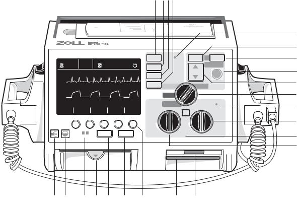
1. SELECTOR SWITCH
The selector switch allows selection of the following modes: OFF, MONITOR, DEFIB, and PACER, (Pacer version only)
2. DEFIB ENERGY SELECT BUTTONS
Two sets of up-down arrow buttons control the defibrillator energy level, one set located on the front panel and the other located on the sternum paddle.
Press and hold the appropriate up (▲)or down (▼) arrow button until the desired energy level is indicated on the display.
3. DEFIB CHARGE
Pressing the CHARGE button on the front panel or, if using paddles, on the apex paddle handle, charges the defibrillator to the selected energy level.
4. SHOCK
The SHOCK button illuminates when the defibrillator is charged and ready. Press and hold the button to discharge the defibrillator.
The SHOCK button is only active when using Multi-Function Electrodes (MFE) Pads, external autoclavable paddles, or internal defibrillation paddles without a discharge button. The SHOCK button is not functional when external paddles are connected to the unit.
Each external paddle has a SHOCK button located near the forward end of the handle. Press and hold both buttons simultaneously to discharge the defibrillator.
2-1

M SERIES OPERATOR’S GUIDE
5. ANALYZE
The ANALYZE button initiates ECG analysis to identify shockable rhythms.
6. SOFTKEYS
Five unlabeled buttons located directly beneath the display control different functions depending on the operating mode of the unit. Labels for the softkeys appear at the bottom of the display directly above each softkey to indicate its function.
7. LEAD
The LEAD button determines selection of the ECG source. Pressing this button sequentially selects ECG signals derived from each of the following lead configurations - "I", "II", "III", “aVR, aVF, aVL, PADDLES" (defibrillator paddles), or "PADS" (Multi-Function Electrode (MFE) Pads) for display. The “PADS” or “PADDLES” Lead setting is automatically selected when the instrument powers up in DEFIB or MONITOR mode and MFE Pads or Paddles are connected to the Multi-Function cable.
Lead II is automatically selected when the M Series unit powers up in PACER mode (Pacer version only). Pads or Paddles monitoring is not available in PACER mode.
8. SIZE
The SIZE button allows you to change the display size of the ECG signal. Size options are 0.5, 1, 1.5, 2, 3 cm/mV and are indicated in the upper right center of the display.
9. ALARM SUSPEND
The ALARM SUSPEND button is used to activate, deactivate and audibly suspend all alarm functions. A
bell symbol () appears in the top-center of the display when the alarms are enabled. When the alarms are either audibly or permanently disabled, an “X” crosses through the bell ( ) symbol.
When the alarms are enabled, and an alarm condition occurs, an audible tone sounds and the bell symbol flashes. To avoid possible confusion with the defibrillator charged tone, the heart rate alarm tone sounds at a different frequency when the Selector Switch is set to
DEFIB.
10. RECORDER
This control starts and stops the strip recorder. There is a RECORDER button located on the unit’s front panel and another located on the sternum paddle.
The unit can be switched to diagnostic ECG bandwidth (0.05-150 Hz) by pressing and holding the RECORDER button.
Diagnostic bandwidth is maintained as long as the RECORDER button is held down. The unit reverts to
standard monitoring bandwidth when the RECORDER button is released.
11. BEEPER VOLUME (ECG)
This button allows for manual adjustment of the QRS beeper tone from maximum volume to inaudible. (The heart rate alarm and charge ready volumes are not adjustable.) Press this button to display a menu for adjusting the volume using softkeys.
12. BRIGHTNESS/CONTRAST ADJUSTMENT
This button causes a menu to appear on the display for adjusting the display brightness using softkeys (contrast on LCD).
13. CHARGER ON
When the M Series products are plugged into AC mains, the CHARGER ON indicators will operate in the following manner:
The orange-yellow CHARGER ON indicator will illuminate continuously whenever; the device is turned OFF and charging the battery or turned ON with a battery installed.
The green CHARGER ON indicator will illuminate continuously whenever; the unit is turned OFF and the installed battery has been fully charged to present capacity.
The green and orange-yellow CHARGER ON indicators will illuminate alternately when; no battery is installed in the unit or a battery charging fault has been detected.
When the device is not connected to AC mains, the CHARGER ON indicators will remain extinguished.
14. Paper Tray
Holds the paper supply for the recorder. Press down and pull to open the drawer and replace the paper.
15. SUMMARY
The SUMMARY button retrieves stored patient information and prints it on the unit recorder as a Summary Report. The Summary Report function automatically collects critical patient ECG data, control settings, date, time and therapies administered during certain events.
See the “Summary Report” section for more information.
16. CODE MARKER
The CODE MARKER button activates a menu and softkeys that allow the unit to record in its internal memory the delivery of specific drugs or treatments.
See the “Code Markers” section for more information.
17. PCMCIA Data Card Slot
Holds the PCMCIA flash memory card for data storage and retrieval.
2-2
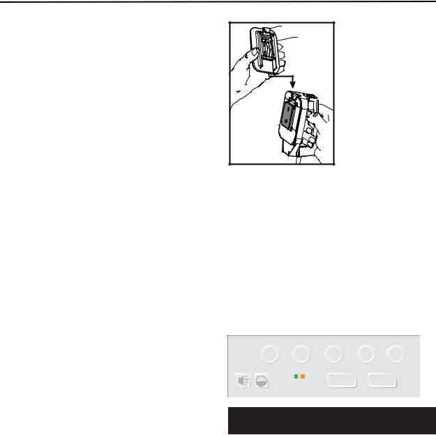
Operating Controls and Indicators
18. PC Card Modem Slot (12-Lead Option Only)
Holds the modem card for transmitting 12-Lead ECG information to remote locations via landline or cellular phone. See the 12-Lead ECG Monitoring insert (part number 9650-0215-01) for more information.
Note: The modem slot is covered by a plastic bezel.
19. PACER OUTPUT mA (Pacer Version Only)
When pacing is selected, this control sets the amount of current delivered to the MFE Pads. For conscious patients, it should be gradually increased until capture is recognized. The selected current setting is indicated on the display.
20. 4:1 BUTTON (Pacer Version Only)
This control is used to test for threshold or to determine the patient’s underlying rhythm. When depressed this button causes pacing stimuli to be delivered at ¼ the indicated ppm setting. Releasing the control causes the instrument to resume normal pacing operation.
21. PACER RATE ppm (Pacer Version Only)
When pacing is selected, this control sets the rate at which the pacemaker will operate. It must be set above the patient’s intrinsic rate in order for the pacemaker to provide stimulation. The selected pace rate setting is indicated on the display.
22. Systole and Alarm Speaker
Emits audible heart rate tone during ECG monitoring, and audible alarm indications when an alarmed condition occurs.
23. Microphone (Optional)
Records audio activity in the vicinity of the M Series unit for storage in non-volatile memory and on the PCMCIA data card.
CHARGE INDICATOR LIGHT (Not Shown)
Located on the apex paddle, this light turns on when the defibrillator is charged and ready.
DEFIBRILLATOR TEST PORT (Not Shown)
Located on the Multi-Function Cable, the test connector is used to test the defibrillator output using the MultiFunction Cable only.
PEDIATRIC PADDLES (Not Shown)
Pediatric-size electrodes are built into the paddle assembly. They lie directly under the adult electrode surface and are accessed by pushing the black PEDI button at the front of each paddle and sliding the adult surface forward. When replacing the adult electrodes, it is important that the electrode is locked correctly in position on the paddle handle.
PEDI Button |
Adult |
Electrode |
(Shoe) |
Pediatric
Electrode
(Plate)
VOLT ECG OUT (Not Shown)
A 1 volt/cm of displayed ECG signal output is available from a subminiature phone jack located on the back of the device. This output may be used for interconnections to patient monitors and radio-telemetry equipment. The tip carries the ECG signal and the sleeve is ground.
Code Markers
Pressing the CODE MARKER button causes the unit to display a preconfigured list of clinical actions. Pressing the softkey associated with a particular action causes that action to be recorded along with a date and time stamp in the Summary Report Memory.
|
|
SUMMARY |
CODE |
|
CHARGER ON |
MARKER |
|
|
|
||
CPR |
EPI |
Atrop DOPA MORE |
|
Up to five Code Markers can be displayed on the screen at one time. The right-most softkey is labeled “MORE” when there are more than five items on the Code Marker list. Pressing the MORE softkey will cause the next set of Code Markers to be displayed above the softkeys. Separate Code Marker lists are maintained for PACER, MONITOR, and DEFIB modes thereby enabling the appropriate Code Markers to be displayed for the particular protocol (e.g. PACE: EPI, Atrop MONITOR: Valium, LIDO DEFIB: BRET, AMIO).
The Code Markers are removed from the display after 10 seconds. If no Code Marker softkey has been pressed in that time, a generic event MARK is stored in Summary Report memory.
2-3
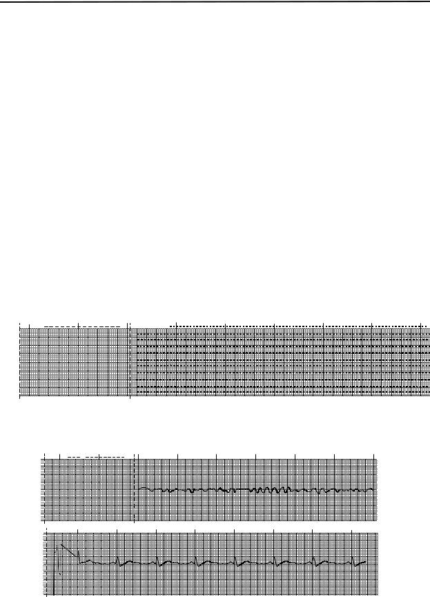
M SERIES OPERATOR’S GUIDE
Summary Report
Summary Report allows you to store and later retrieve important ECG and device event information. The unit’s internal memory automatically records defibrillation and cardioversion segments, PACER mode (Pacer version only), heart rate alarm and ECG segments upon activation of the stripchart recorder. Associated event information including device control settings, patient ECG, time and date are recorded as well.
Note: Diagnostic bandwidth recordings are not included in Summary Report. Six events will trigger Summary Report to automatically record information:
•VF Alarm triggered
•Defibrillator Shock
•Selecting PACER mode (Pacer version only)
•Heart Rate Alarm triggered
•Turning Strip Recorder on (or on and then off in rapid sequence)
•Initiating analysis of the ECG
Summary Report records each event in chronological order and will store up to 65 defibrillation or 140 recorderactivated ECG events. All event data will remain in memory and be accessible until data is manually erased. A new patient record is automatically created if the unit has been turned off for a user configurable time period of 5 minutes to 36 hours. If all memory has been used for a particular patient, a “REPORT FULL” message will appear on the display and no further data is recorded.
Summary Report Formats
Summary Report prints an overview of all the events currently stored in memory including total number of defibrillation shocks delivered, total pacing time (cumulative), time and date the device was turned on (or if you have just manually erased summary reports, then start time and date of the next report), time of last event, as well as space for patient name, date and comments. All segments have vertical dashed cut lines every 8.5 inches to facilitate easy mounting on 8.5" x 11" paper. On the last event recorded “SUMMARY COMPLETE” will be printed at the bottom left of the recorder strip.
NAME |
COMMENTS |
SUMMARY REPORT |
|
DATE |
I I |
REPORT START |
2 |
LAST EVENT TIME |
38 |
|
|
TOTAL SHOCKS |
1 |
PACER TOTAL TIME |
00:01:21 |
Defibrillation Format
Summary Report records 6 seconds of pre-shock and 8 seconds of post-shock patient ECG data. Also recorded are joules selected, joules delivered, sync if active, (includes sync markers), ECG lead, ECG size, patient impedance, time and date. AED units will additionally include shock count and AED mode annotations.
JOULESNAMESELECTED |
PRE SHOCK 15:18:45 10 MAY 93 |
DEFIBRILLATION |
|
ECG LEAD |
I I |
ECG SIZE |
1 |
IMPEDANCE |
65 |
JOULES SELECTED |
200 |
JOULES DELIVERED |
202 |
POST SHOCK 15:18:45
2-4

Operating Controls and Indicators
Pacer Format (Pacer version only)
Summary Report records 6 seconds of pre-pacer patient ECG data. Also recorded are the ECG lead, ECG size, patient's heart rate, time and date.
NAME |
15:19:50 10 MAY 93 |
PRE-PACE ECG |
|
ECG LEAD |
I I |
ECG SIZE |
2 |
HEART RATE |
38 |
After establishing a paced rhythm, turning the recorder on briefly will record the paced rhythm for later reports. If async pace is active, the annotation “ASYNC PACE” is also recorded.
NAME |
15:19:50 10 FEB 98 |
RECORDED ECG |
|
ECG LEAD |
I I |
ECG SIZE |
2 |
HEART RATE |
38 |
PACE RATE ppm |
62 |
PACE CURRENT mA |
38 |
Heart Rate Alarm Activated Format
Summary Report records 6 seconds of pre-alarm patient ECG. Also recorded are the ECG lead, ECG size, patient’s heart rate, time, and date. If the pacer is on during this event the pacing rate and pacing current are also recorded.
NAME |
15:21:47 10 MAY 93 |
HEART RATE ALARM |
|
ECG LEAD |
LEAD I I |
ECG SIZE |
2 |
HEART RATE |
41 |
VF Alarm Activated (Refer to Section 8)
The summary report records 15 seconds of patient ECG data associated with each “VF” alarm. Also recorded are the shock count, ECG lead, ECG size, patient’s heart rate, and noise events.
NAME |
15:19:50 10 FEB 98 |
CHECK PATIENT |
DEFIB ADVISORY |
|
|
AUTO DEFIB MODE |
|
|
SHOCK COUNT |
1 |
|
ECG LEAD |
ELECTRODES |
|
ECG SIZE |
1 |
|
HEART RATE |
283 |
|
NOISE EVENTS |
0 |
|
CHECK PATIENT |
|
|
SUMMARY COMPLETE |
|
|
Recorder On Format
Summary Report records 6 seconds of patient ECG prior to turning on the recorder. Also recorded are the ECG lead, ECG size, patient’s heart rate, time, and date. If the Pacer is on during this event the pacing rate and pacing current are also recorded. If async pace is active, the annotation “ASYNC PACE” is recorded. AED units will additionally include shock count and AED mode annotations.
NAME |
15:19:50 10 FEB 98 |
RECORDED ECG |
|
ECG LEAD |
I I |
ECG SIZE |
2 |
HEART RATE |
45 |
2-5
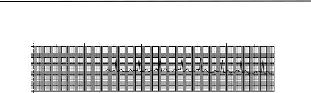
M SERIES OPERATOR’S GUIDE
Analyze Format
The summary report records 6 seconds of pre analysis ECG and 9 seconds of ECG recorded during the ECG analysis interval with the annotation “SHOCK ADVISED” or “NO SHOCK ADVISED”. AED units will additionally include shock count and AED mode annotations.
NAME |
|
09:56:26 10 FEB 98 NO SHOCK ADVISED |
DEFIB ADVISORY |
|
|
ECG LEAD |
ELECTRODES I |
|
ECG SIZE |
2 |
I |
NOISE EVENTS |
0 |
|
NO SHOCK ADVISED |
|
|
Manual Mode Activated
AED versions of the M Series that are equipped with manual mode capabilities will record a “MANUAL MODE STARTED” event within Summary Report whenever the device is switched from the AED (Default) mode to the Manual operating mode.
The following annotations may also be printed at the top of the Analyze Format printout:
Annotation |
Description |
|
|
|
|
1. |
POOR PAD CONTACT: |
The MFE Pads are detected as having poor connection. |
|
|
|
2. |
ANALYSIS HALTED: |
The ECG analysis is halted due to either the ANALYZE button being pushed or a fault |
|
|
condition. |
|
|
|
3. |
NOISY ECG: |
Excessive noise is detected. |
|
|
|
4. |
SHOCK ADVISED: |
Shockable rhythm has been detected at the end of user-initiated ECG analysis. |
|
|
|
5. |
NO SHOCK ADVISED |
No shockable rhythm has been detected at the end of user-initiated ECG analysis. |
|
|
|
6. |
ECG TOO LARGE |
The amplitude of the ECG signal is too large for proper rhythm analysis. |
|
|
|
2-6

Operating Controls and Indicators
Printing a Report
To print the stored information, press the SUMMARY button below the screen display. Then press the corresponding softkey to print configuration settings, print chart, or print log.
|
|
|
|
|
|
|
SUMMARY |
CODE |
|
|
|
|
|
|
|
||
|
|
CHARGER ON |
MARKER |
|||||
|
|
|||||||
|
|
|
||||||
|
|
|
|
|
|
|
|
|
The recorder will print all events currently in memory in chronological order. If the stripchart recorder is on or the defibrillator is charged, summary report printing is disabled. To stop printing a report, press the RECORDER button or turn the unit off. An unlimited number of copies of the report may be printed by simply pressing the SUMMARY button and corresponding print softkey again.
Pressing the RECORDER button while printing a Summary Report will cause the unit to stop printing the report. Press the RECORDER button again to begin printing an ECG trace. The stripchart recorder will run continuously until the button is pressed again.
Pressing the SUMMARY button and a corresponding print softkey while printing a report will cause the current report to stop printing and a new report to begin printing.
Printing is interrupted if a vital sign alarm occurs (i.e. HR, SpO2, etc.), the ANALYZE button is pressed, or the
defibrillator is charged.
If the recorder is out of paper when the SUMMARY button and a corresponding print softkey are pressed, a “CHECK RECORDER” message will appear on the display. Load paper and press SUMMARY again to select the report to print.
Printing Part of a Report
If you want to print out only a portion of the Summary Report:
1.Press the SUMMARY button.
2.Press the Print Chart softkey.
3.Press the Print Range softkey.
4.Press Prev. Event or Next Event softkey to scroll through the events.
5.Press Print softkey.
The M Series unit prints the displayed event and all following events.
Adding Patient Name and ID# to a Report
To add patient name and identification number to the summary report:
1.Press ID # softkey.
2.Press Prev. Digit or Next Digit softkey to select letter for patient name.
3.Press Inc Digit or Dec. Digit softkey to change value of letter.
Repeat steps 2 and 3 until you have entered the patient’s entire name.
4.Press Enter Name softkey.
5.Press Prev. Digit or Next Digit softkey to select digit or letter for identification number.
6.Press Inc Digit or Dec. Digit softkey to change value of digit.
Repeat steps 5 and 6 until you have entered the patient’s entire identification number.
7.Press Enter ID and Return softkey.
Note: Patient name cannot be retrospectively added to summary report events already stored in memory. The patient name is only stored with summary events saved after the patient name has been entered.
Printing an Incident Log
An incident log is an abbreviated list of all major events recorded in the summary report. You can print out an incident log that includes the time of occurrence of the following events:
•M Series unit powered on.
•Defibrillation advisory messages (for example, CHECK PATIENT and SHOCK ADVISED).
•Defibrillation shocks (including energy level).
•Pacer mode activated.
•Manual mode started (AED only).
•Alarms triggered.
•Code markers.
•12 Lead analysis initiated.
•12 Lead data transmission.
•Recorder turned on.
•NIBP measurements activated.
In addition, the incident log lists the following:
•Report start time (time when summary report memory was erased).
•Last event time (time of last event in memory).
•Total number of shocks.
•Total pacer time.
•System serial number.
•Device identification number.
2-7
 Loading...