


Two Locations
916 Delaware Avenue • Marysville, Ohio 43040 984 East Greg Street • Sparks, Nevada 89431-6521
www.ZLineKitchen.com
www. TheRangeHoodStore.com
Table of Contents
Installation for: |
|
Walls............................................................................... |
4 |
Designer Walls.............................................................. |
9 |
Crown Molding............................................................. |
14 |
Islands............................................................................ |
15 |
Under Cabinets............................................................ |
19 |
Inserts............................................................................. |
22 |
Remote Blower Installation......................................... |
25 |
How to Change Parts................................................... |
29 |
Trouble Shooting and FAQ’s........................................ |
40 |
Warranty and Disclaimer ........................................... |
43 |
Proper Venting Regulations Disclaimer
Please verify with your local, city and state regulations on the proper venting method for your hood.
ManyagencieshaveCFMratingspecificationsforyourhoodaswell.Youmayhavetopurchaseadditionalitemsonyourowntoventthehoodinaccordancewithyourlocalcityandstatespecifications.
Our ZLine dual motor range hoods come with an 8” metal transition piece without a backdraft damper and a piece of 4’ metal ducting.
Our ZLine single motor units come with a plastic 6” plastic transition piece with a backdraft damper and a 4’long piece of flexible ducting.
1

Important Safety Notice
Read all instructions before installing and operating this appliance.
►The installation instructions in this manual is intended for qualified installers, service technicians or persons with similar qualified background. Installation and electrical wiring must be done by qualified professionals and in accordance with all applicable codes and standards, including first-rated construction.
►DO NOT attempt to install this appliance yourself. Injury could result from installing the unit due to lack of appropriate electrical and technical background.
►Range hood may have very sharp edges; please wear protective gloves if it is necessary to remove any parts for installing, cleaning or servicing.
►Activating any switch ON before completing installation may cause ignition or an explosion. ►Due to the size and weight of this range hood, two people installation is recommended.
 To reduce the risk of fire, electric shock or injury to persons:
►For general ventilating use only. DO NOT use to exhaust hazardous or explosive materials and vapors. ►The combustion air flow needed for safe operation of fuel-burning equipment may be affected by this unit’s operation. Follow the heating equipment manufacturer’s guideline and safety standards such as those published by the National Fire Protection Association (NFPA), and the American Society of
Heating, Refrigeration and Air Conditioning Engineers (ASHRAE), and the local code authorities. ►Before servicing or cleaning unit, switch power OFF at service panel and lock service panel to prevent
power from being switched ON accidentally.
►Ducted fans MUST ALWAYS be vented to the outdoors. ►Use only metal ductwork, and this unit MUST be grounded.
►Sufficient air is needed for proper combustion and exhausting of gases through the duct to prevent back drafting.
►When cutting or drilling into a wall or ceiling, be careful not to damage electrical wiring or other hidden utilities.
►All electrical wiring must be properly installed, insulated and grounded.
►Old duct work should be cleaned or replaced, if necessary, to avoid the possibility of a grease fire. ►Check all joints on duct work to insure proper connection, all joints should be properly taped. ►Use this unit only in the manner intended by the manufacturer. If you have any questions, contact
the vendor.
►Keep all fans, baffle, spaces, filter, grease tunnel, oil container and grease-laden surfaces clean. Grease should not be allowed to accumulate on fan, baffle, spaces, filter, grease tunnel or oil container.
►Clean grease-laden surfaces frequently. To reduce the risk of fire and to disperse air properly, make sure to vent air outside. DO NOT vent exhaust into spaces between walls, crawl spaces, ceilings, attics or garages.
►Always turn range hood ON when cooking at high heat or when cooking flaming foods. ►Use high settings on cooking range only when necessary.
2
Important Safety Notice
►Never leave surface units unattended at high settings. Boil overs cause smoking and greasy spillovers that may ignite. Heat oils slowly on low or medium settings.
►Clean ventilating fan frequently.
►Always use appropriate cookware and utensils size.
►Always use cookware appropriate for the size of the surface element.
 To reduce the risk of injury to persons in the event of a stove top grease fire:
►SMOTHER FLAMES with a close-fitting lid, cookie sheet or metal tray, then turn OFF the burner. NEVER PICK UP A FLAMING PAN—you may be burned. KEEP FLAMMABLE OR COMBUSTIBLE MATERIAL AWAY FROM FLAMES. If the flames DO NOT go out immediately, EVACUATE AND CALL THE FIRE DEPARTMENT.
►DO NOT USE WATER, including wet dishcloths or towels—a violent steam explosion will result. ►Use an extinguisher ONLY if:
●You know you have a Class A, B, C extinguisher and you already know how to operate it.
●The fire is small and contained in the area where it is started.
●The fire department is being called.
●You can fight the fire with your back to an exit.
 To reduce the risk of injury to persons in the event of gas leaks:
►Extinguish any open flame.
►DO NOT turn on the lights or any type of appliance.
►Open all doors and windows to disperse the gas. If you still smell gas, call the gas company and fire department.
Your safety and the safety of others is very important. We have provided many important safety messages in this manual and on your appliance. Always read and obey all safety messages. All safety messages will tell you what the potential hazard is, tell you how to reduce the chance of injury, and tell you what can happen if the instructions are not followed.
This is the safety alert symbol. This symbol alerts you to potential hazards that can hurt you and others. All safety messages will follow the safety alert symbol
and the word “WARNING”.
WARNING
3
Wall Range Hood Installation
Installation
Tutorial Video
4
 Please unpack your range hood when it is delivered and inspect to ensure all parts are included.
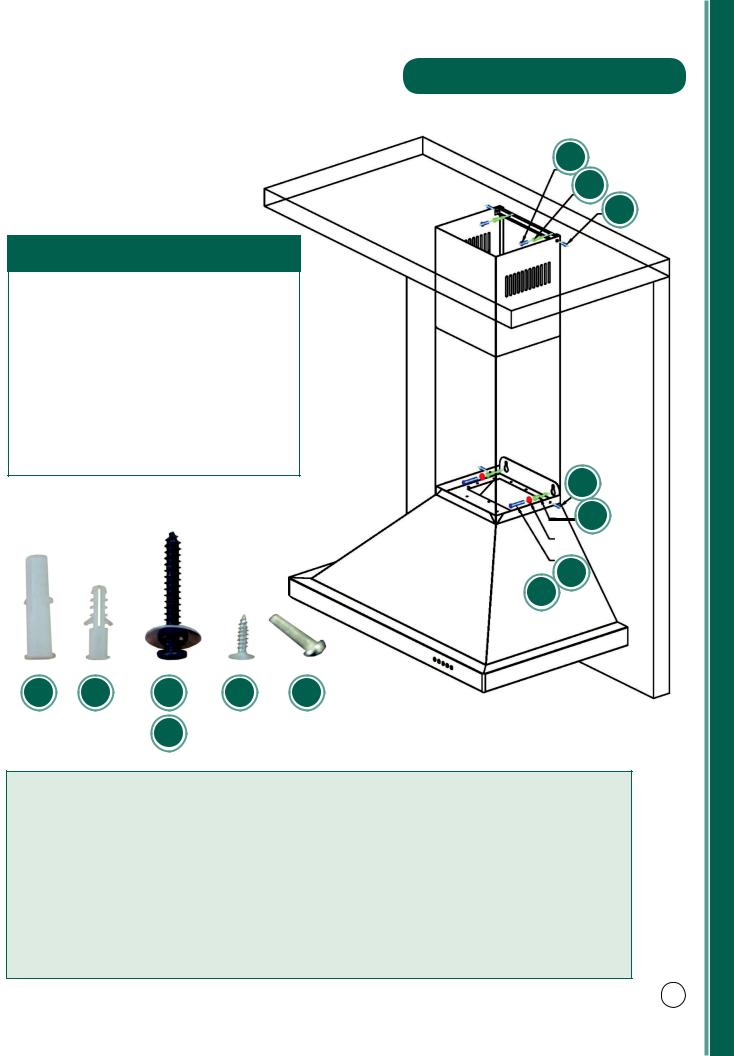
Parts Supplied:
1.Main Hood With All Lights and Button Banks Pres-installed
2.Adjustable Stainless Chimney Cover
3.Transition Piece (For 6˝ or 8˝)
4.Baffle Filters
5.Flexible Duct (For 6˝ or 8˝)
6.Packet of Screws and Anchors
7.Top Mounting Bracket
8.Grease Cup
A B C E F
D
Wall Range Hood Installation
E
B
F
6 A
D
C
*Note: Wall range hoods with single motors will come with a square to 6˝ round transition piece and will include a back draft damper. The ducting with these range hoods is 6˝.
Dual motor wall hoods will come with a square to 8˝ round transition piece without a back draft damper. The ducting with these range hoods is 8˝.
*Use rigid ducting wherever possible. Try and minimize the use of elbows. More elbows and longer runs create higher static pressure. The hood comes with a grounded three prong plug that can either be direct wired or plugged into a 20 amp. circuit.
5
Wall Range Hood Installation
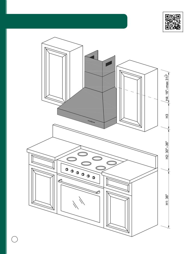
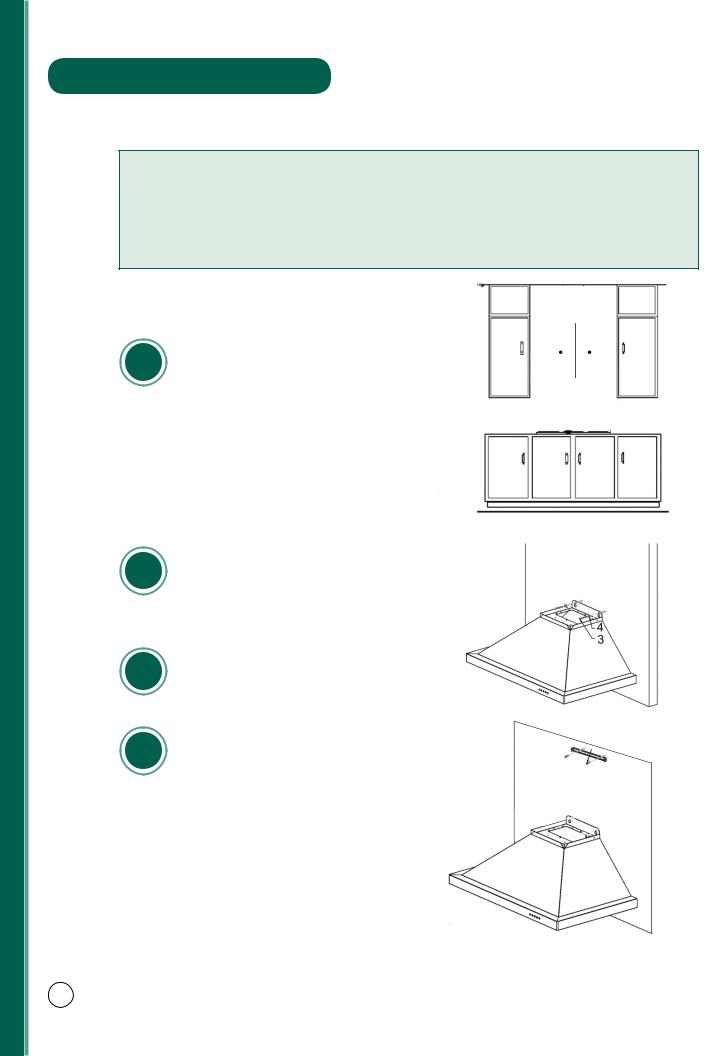
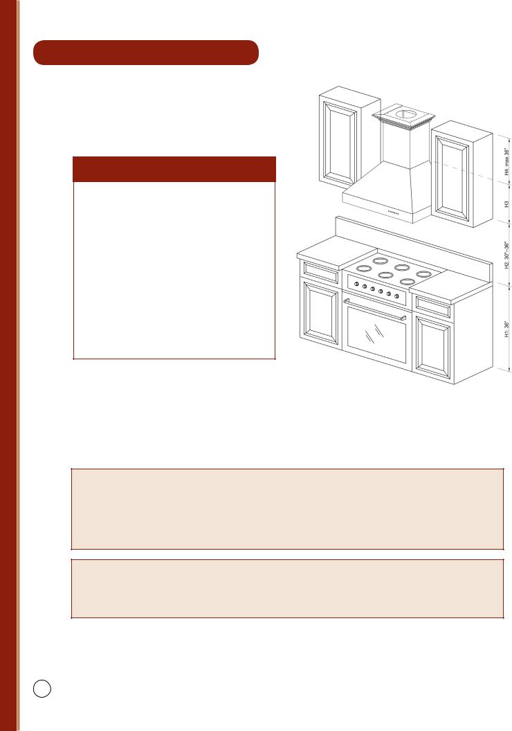
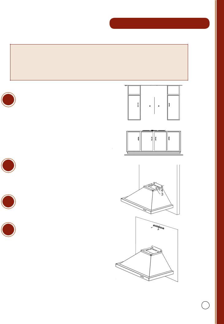
*The recommended height to install your hood is 30˝ minimum and 36˝ maximum above the cooktop.
*For Outdoor (304 Series) hood installation, the unit must be installed at a minimum of 36˝ above the grill.
1 |
Find the center of the wall where you |
|
are installing the hood. Make sure |
||
|
||
|
there is sufficient bracing to hold the |
|
|
weight of the hood. Mark your center |
|
|
line and measure out from the center |
|
|
to find your two mounting points. |
|
|
Make sure your mounting points are |
|
|
level when you mark them. It is rec- |
|
|
ommended to install the hood direct- |
|
|
ly into wood supports. (Figure 1) |
|
2 |
Mark the mounting points and install |
|
the two mounting screws provided |
|
leaving the heads out ¼˝ to mount the |
|
|
hood. (Figure 1) |
|
3 |
Mount the main body of the hood to |
|
the two screws and screw into place. |
||
|
||
|
(Figure 2) |
|
4 |
Mount the top chimney mounting |
|
bracket centering it above the hood. |
||
|
||
|
(Figure 3) |
Figure 1
Figure 2
Figure 3
6
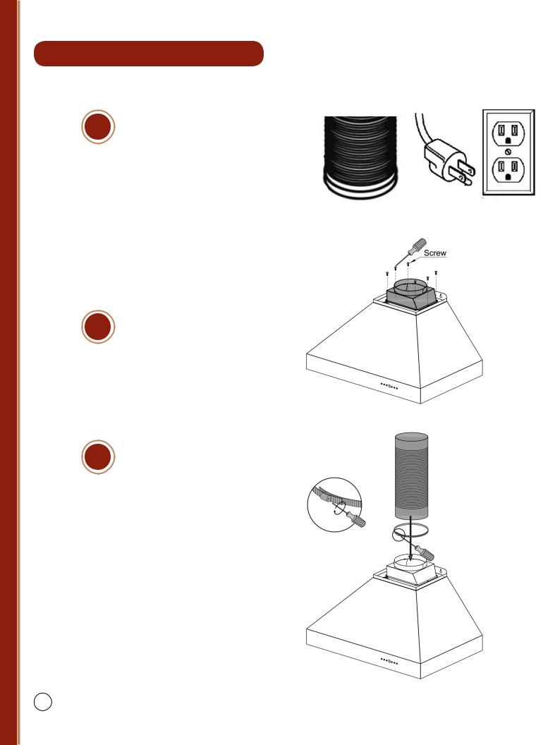
5 |
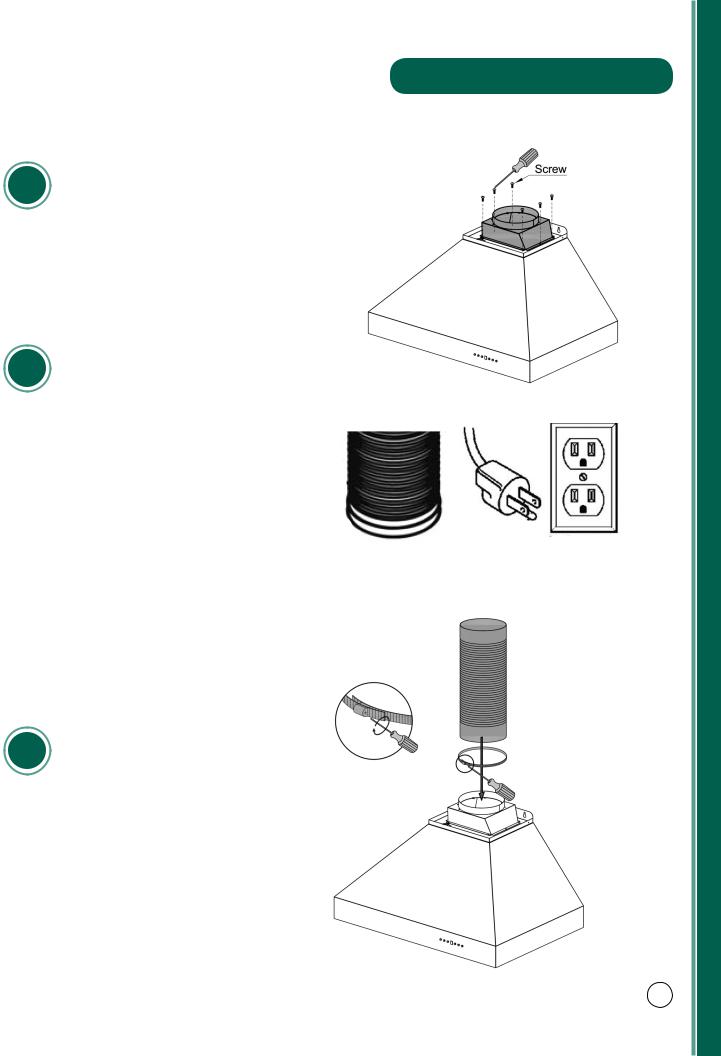
Install the transition piece securing it |
|
with screws provided. (Figure 4) |
||
|
6 |
Make your electrical and ducting |
|
connections. Try and minimize the |
||
|
||
|
use of elbows. More elbows and lon- |
|
|
ger runs create higher static pressure. |
|
|
The hood comes with a grounded |
|
|
three prong plug that can either be |
|
|
direct wire or plugged into a 20amp. |
|
|
circuit. (Figure 5) |
7 |
Connect the ducting to the transition |
|
piece using ring to hold into place. |
||
|
||
|
Attach ducting to the range hood. |
|
|
(Figure 6) |
Wall Range Hood Installation
Figure 4
Figure 5
Figure 6
7
Wall Range Hood Installation
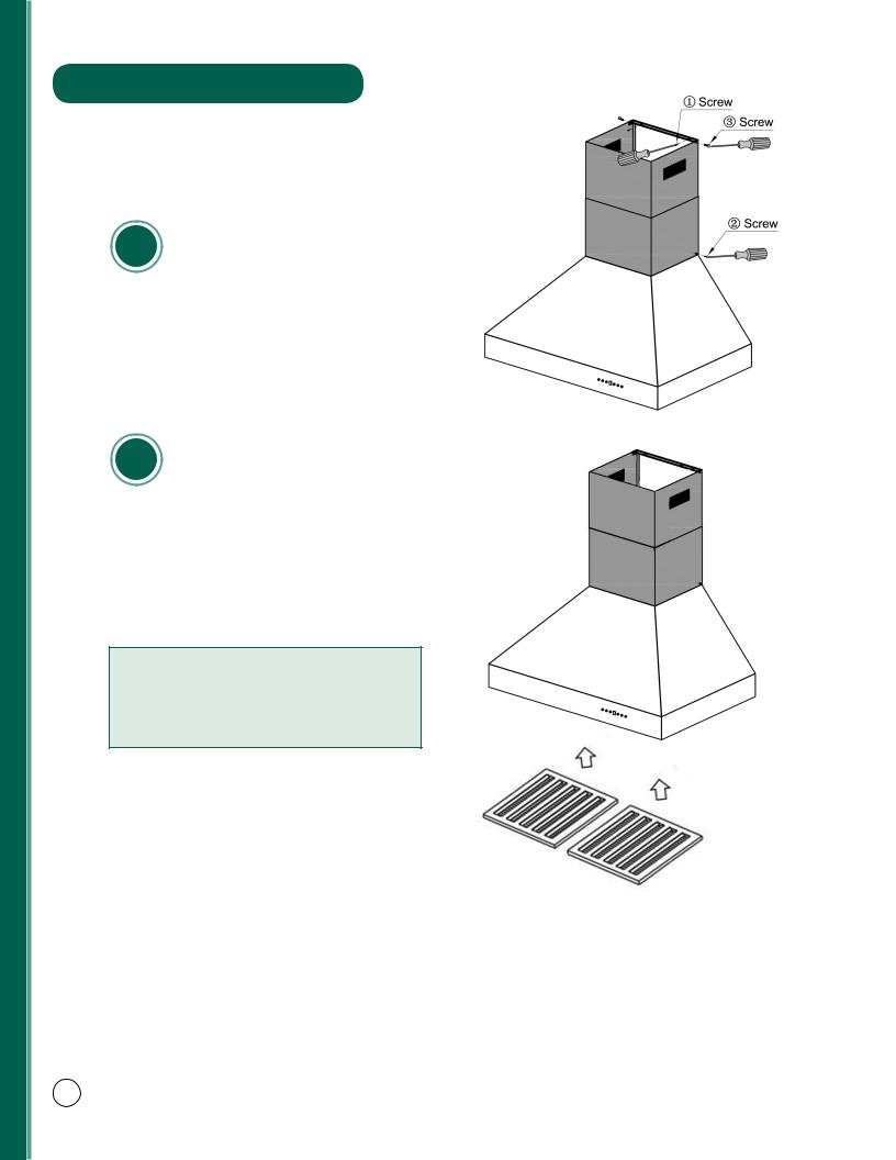
8 |
Install the two part chimneys on top |
|
of the hood. Slide the inside section |
||
|
||
|
up until the vertical vent slots are vis- |
|
|
ible, attach top portion to mounting |
|
|
bracket with screws. Secure lower |
|
|
chimney portion to the hood with |
|
|
screws provided. (Figure 7) |
9 |
Install plastic drip cup by sliding into |
brackets located at the bottom of the |
motor. Install baffle channel and baffle filters. (Figure 8)
Not all models include baffle channels.
*Before installing baffle filters, make sure that you insert the grease cup under the motor blower.
Figure 7
Figure 8
8

Designer Wall Range Hood Installation
Installation
Tutorial Video
9
Designer Wall Range Hood Installation
 Please unpack your range hood when it is delivered and inspect to ensure all parts are included.
Parts Supplied:
1.Main Hood With All Lights and Button Banks Pre-installed
2.Chimney
3.Transition Piece (For 6˝ or 8˝)
4.Baffle Filters
5.Flexible Duct (For 6˝ or 8˝)
6.Packet of Screws and Anchors
7.Top Mounting Bracket
8.Crown Molding Bracket
9.Crown Molding
10. Grease Cup
*Note: Wall range hoods with single motors will come with a square to 6˝ round transition piece and will include a backdraft damper. The ducting with these range hoods is 6˝.
Dual motor wall hoods will come with a square to 8˝ round transition piece without a backdraft damper. The ducting with these range hoods is 8˝.
*Note: Use rigid ducting wherever possible. Try and minimize the use of elbows. More elbows and longer runs create higher static pressure. The hood comes with a grounded three prong plug that can either be direct wired or plugged into a 20 amp. circuit.
10
Designer Wall Range Hood Installation
*The recommended height to install your hood is 30˝ minimum and 36˝ maximum above the cooktop.
*For Outdoor (304 Series) hood installation: The unit must be installed at a minimum of 36˝ above the grill.
1 |
Find the center of the wall where you |
are installing the hood. Make sure |
|
|
there is sufficient bracing to hold the |
|
weight of the hood. Mark your center |
|
line and measure out from the center |
|
to find your two mounting points. |
|
Make sure your mounting points are |
|
level when you mark them. It is rec- |
|
ommended to install the hood direct- |
|
ly into wood supports. (Figure 1) |
2 |
Mark your mounting points and in- |
stall the two mounting screws provid- |
|
|
ed leaving the heads out ¼˝ to mount |
|
hood. (Figure 1) |
3 |
Mount the main body of the hood to |
the two screws and screw into place. |
(Figure 2)
4 |
Mount the crown molding bracket |
|
|
|
centering it above the hood. (Figure3) |
Figure 1
Figure 2
Figure 3
11
Designer Wall Range Hood Installation
Make your electrical and ducting 5 connections. Try and minimize the
use of elbows. More elbows and lon- |
|
|
ger runs create higher static pressure. |
|
|
The hood comes with a grounded |
|
|
three prong plug that can either be |
|
|
direct wire or plugged into a 20amp. |
Figure 4 |
|
circuit. (Figure 4) |
||
|
Figure 5
6 |
Install the transition piece securing it |
|
with screws provided. (Figure 5) |
7 |
Connect the ducting to the transition |
piece using ring to hold into place. |
(Figure 6)
Figure 6
12
 Loading...