


TF1700

Installation Guide
TF1700
Standalone Outdoor Fingerprint Reader Controller
&
ZKAccess | Classic software 3.5
ZKAccess.com
2
TF1700
Stick this mounting paper to the wall
or door frame. Drill the holes according
to the mounting paper.
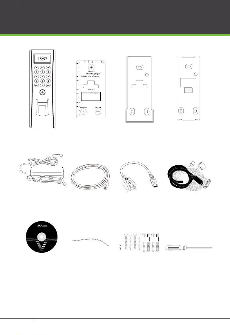
What’s in the Box
TF1700
Installation Template Back PlateRubber Gasket
AC Power Adapter USB Cable AdaptorNetwork Cable Cables
ZKAccess Security Management Software
DiodeZKAccess Software
4 Large Screws & Anchors,
Screwdriver
2 Small screws
TF1700 & ZKAccess CLASSIC 3.5 software INSTALLATION GUIDE

CONTENT
What’s in the Box ....................................................................2
Optional accessories ............................................................ 4
Safety Precautions..................................................................5
Product PIN Diagram ...........................................................6
Product Dimension ...............................................................8
Cables and Connectors .....................................................9
Mounting the reader on the wall ............................10
Power Connection .............................................................11
RS485 Connection .............................................................. 12
PC Connection ......................................................................... 12
FR1200 Connection ................................................................ 13
Lock Relay Connection ...................................................14
Normall Open Lock ................................................................. 14
Normall Close Lock ................................................................. 15
Aux. Input Connection .................................................... 16
Exit Button Connection ......................................................... 16
Aux. Output Connection ...............................................17
Alrm Button Connection ....................................................... 17
Door Bell Button Connection............................................... 18
Weigand Input Connection ........................................19
RFID Button Connection ....................................................... 19
Weigand Output Connection ....................................20
Access Control Panel ..............................................................20
Standalone Installation ................................................... 21
FR1200 Connection ................................................................ 21
Installation with Third Party Panels .........................22
C3 Conroller Panel Connection ........................................... 22
inBIO Conroller Panel Connection ...................................... 23
How Does TF1700 work .................................................24
Troubleshooting ..................................................................25
How to Place a Finger on Scanner .........................26
Electrical Specifications ................................................. 28
Specifications ........................................................................29
3
ZKAccess | CLASSIC 3.5
Software Installation and Setup
starts at page 30
TF1700 & ZKAccess CLASSIC 3.5 software INSTALLATION GUIDE
4
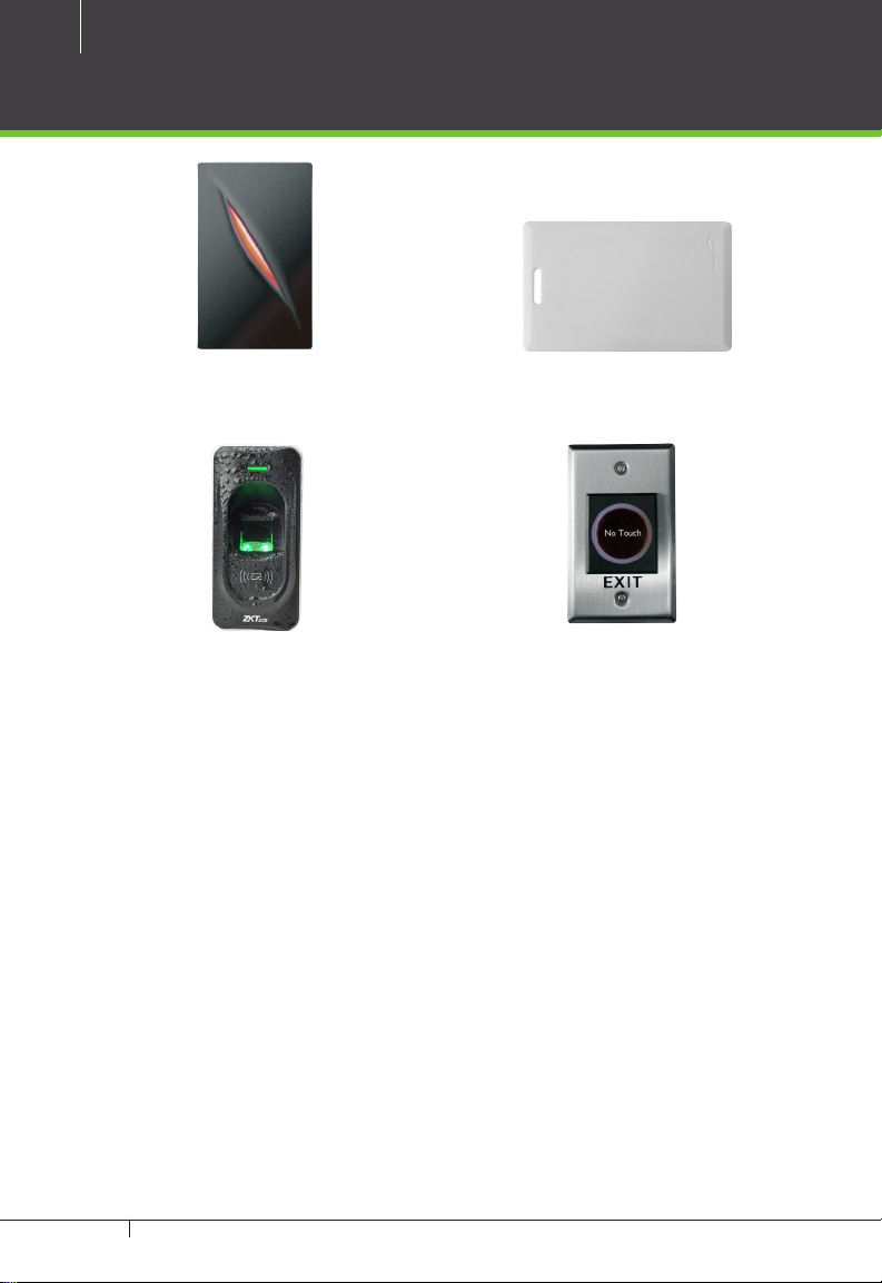
Optional accessories
Wiegand Card Reader
FR1200 FP Reader
Prox Card
K1-1 Exit Button
TF1700 & ZKAccess CLASSIC 3.5 software INSTALLATION GUIDE

Safety Precautions
The following precautions are to keep user’s safe and prevent any damage.
Please read carefully before installation
Do not install the device in a place subject to direct sun
light, humidity, dust or soot
Do not place a magnet near the product. Magnetic objects
such as magnet, CRT, TV, monitor or speaker may damage
the device.
Do not place the device next to heating equipment
Be careful not to let liquid like water, drinks or chemicals
leak inside the device.
Do not let children touch the device without supervision
5
Do not drop or damage the device
Do not disassemble, repair or alter the device.
Do not use the device for any other purpose than specied.
Clean the device often to remove dust on it. In cleaning, do
not splash water on the device but wipe it out with smooth
cloth or towel.
Contact your supplier in case of a problem.
TF1700 & ZKAccess CLASSIC 3.5 software INSTALLATION GUIDE
6
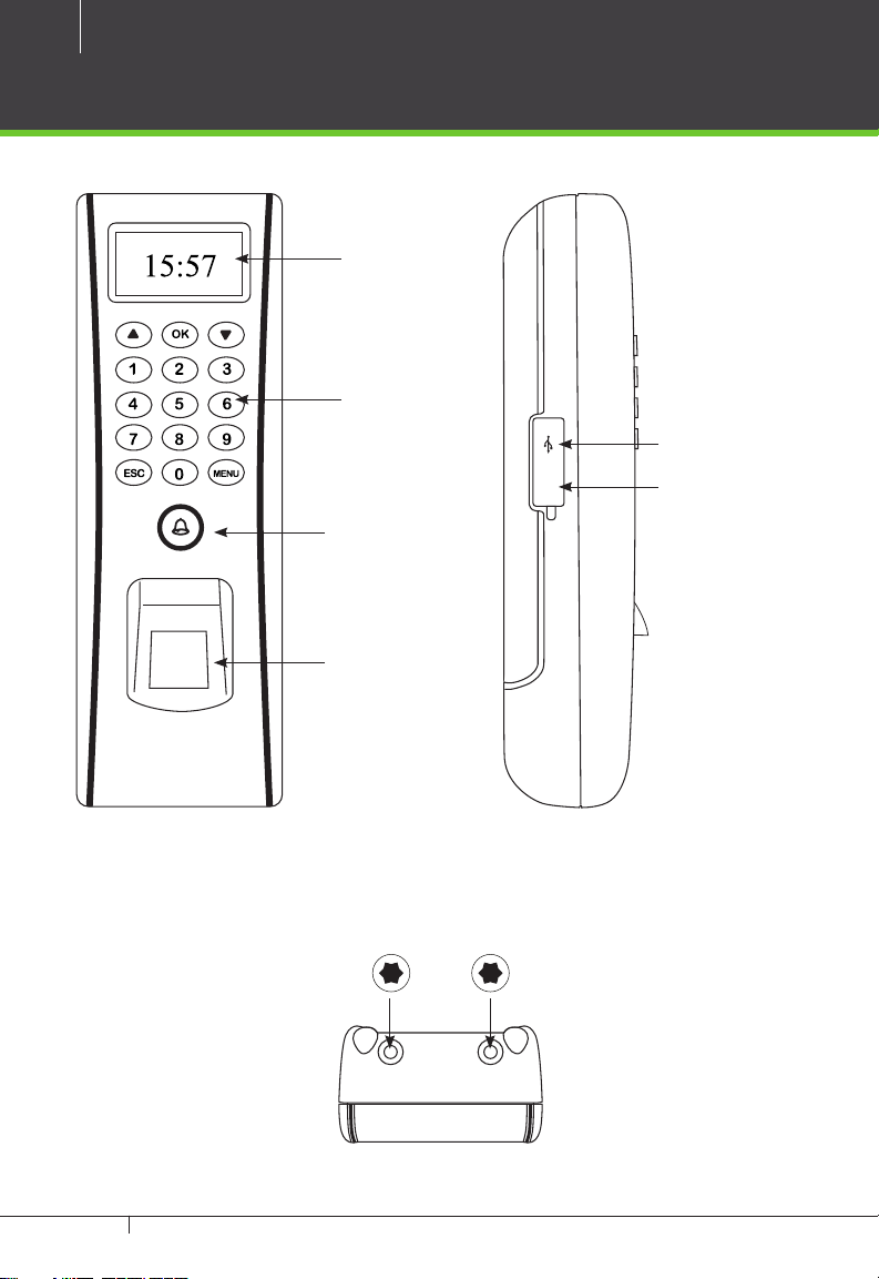
Product PIN Diagram
OLED
Display
3x5 Keypad
Reset
Door Bell &
LED Indicator
Area
ZK Optical
Sensor
Star-shaped screw hole for xing reader to the back plate
USB Host
Reset Switch
TF1700 & ZKAccess CLASSIC 3.5 software INSTALLATION GUIDE
SN 000000000000
Fingerprint Access Control
Manufacturing license No: 75569364-2
SBTS Registered No: H0201
Power Supply DC 12V == 3A
Operating Environment Temperature: 0ºC-45ºC
ISO9000 :
2008 CE FC RoHS
69370226
7
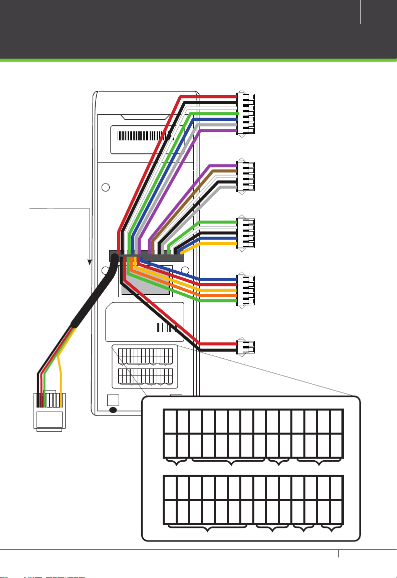
7 pin Cable connectors
5 pin Cable connectors
5 pin Cable connectors
1234567
8
Fingerprint Access Control
Manufacturing license No: 75569364-2
SBTS Registered No: H0201
Power Supply DC 12V == 3A
Operating Environment Temperature: 0ºC-45ºC
2008 CE FC RoHS
ISO9000 :
SEN
BELL-
BELL+
White
Purple
Brown
Bell LOCK Alarm Ethernet
GND
+12V
IWD1
Red
Black
White
RJ 45
Ethernet
69370226
NO2
NO1
BUT
GND
YNC1
COM2
COM1
RJ45-1
RJ45-2
RJ45-3
RJ45-6
:::
:
Red
Blue
Gray
Black
Green
Yellow
Orange
485-
485+
GND
GND
WD0
WD1
+12V
BEEP
RLED
GLED
IWD0
Blue
Green
Red
Blue
Gray
Black
Black
Green
White
Yellow
Purple
Power485WG-OutReader
BELL-
Purple
Bell LOCK Alarm Ethernet
+12V
Red
5 pin Cable connectors
2 pin Cable connectors
BELL+
Brown
GND
Black
SEN
White
IWD1
White
GND
Black
IWD0
Green
BUT
Gray
RLED
Blue
NO1
Blue
GLED
Gray
COM1
Red
BEEP
Purple
YNC1
Yellow
WD0
Green
NO2
Orange
WD1
White
COM2
Green
GND
Black
RJ45-1
:
485+
Blue
RJ45-2
:
485-
Yellow
RJ45-3
:
+12V
Red
Power485WG-OutReader
TF1700 & ZKAccess CLASSIC 3.5 software INSTALLATION GUIDE
RJ45-6
:
GND
Black
8
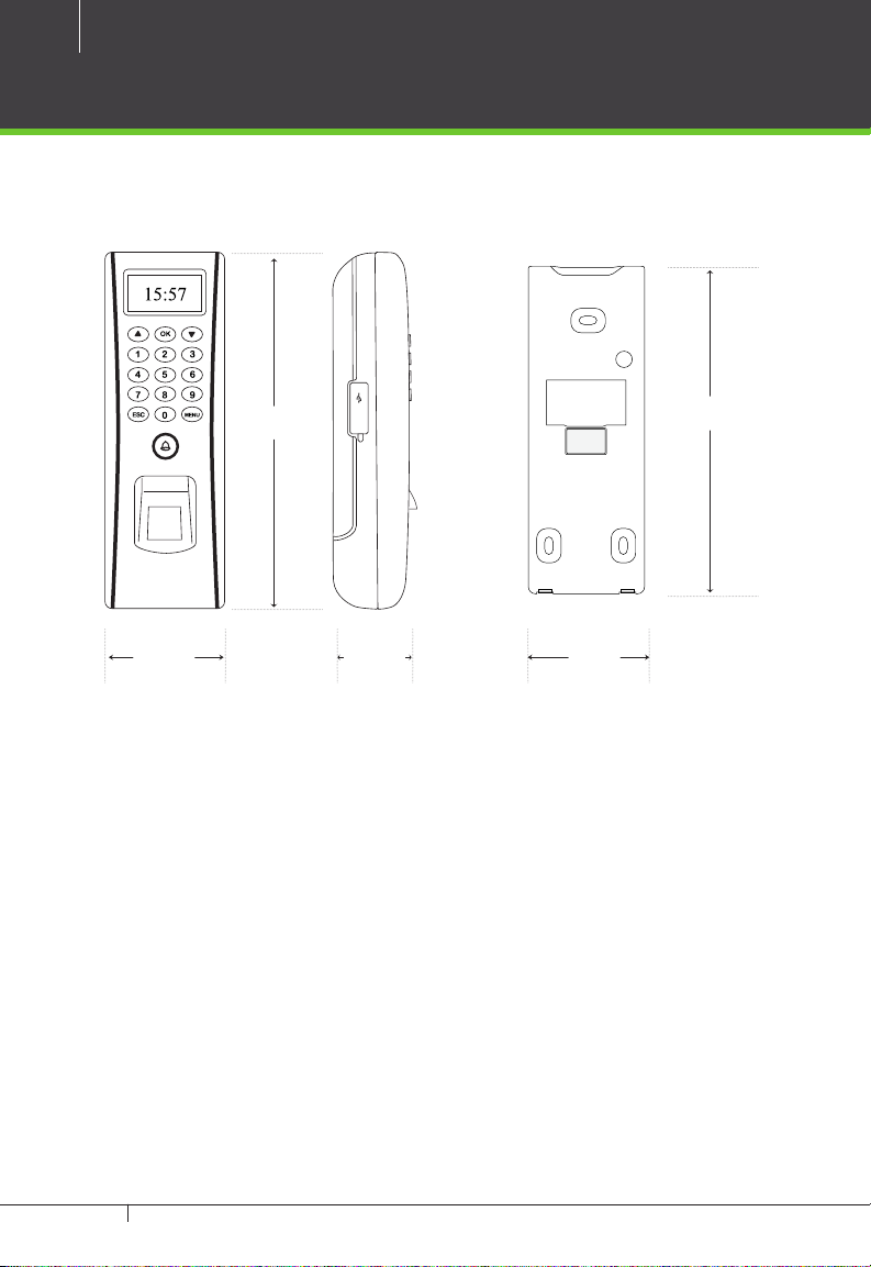
Product Dimension
2.46in
(62.5mm)
7.28in
(185mm)
Reset
1.63in
(41.5mm)
2in
(51mm)
6.125in
(153mm)
TF1700 & ZKAccess CLASSIC 3.5 software INSTALLATION GUIDE
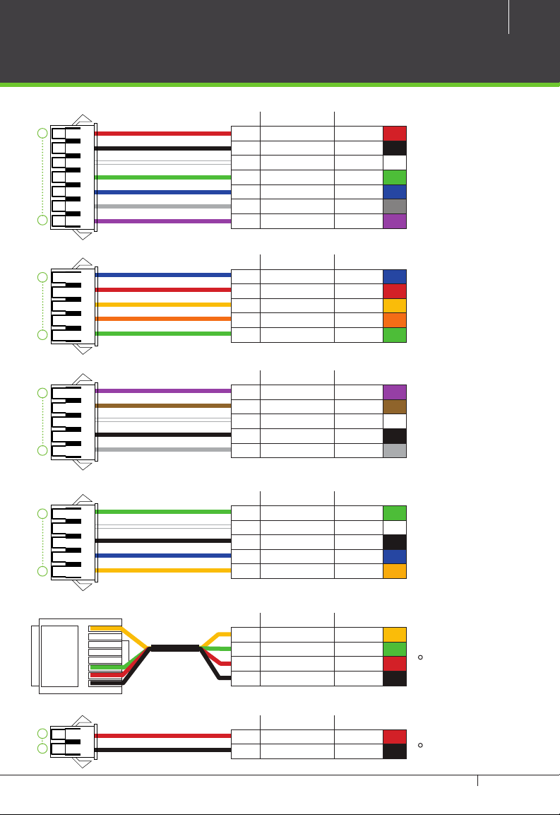
Cables and Connectors
9
1
7
1
5
1
5
1
5
PIN DESCRIPTION WIRE
1 +12V Red
2 GND Black
3 IWD1 White
4 IWD0 Green
5 RLED Blue
6 GLED Gray
7 BEEP Purple
PIN DESCRIPTION WIRE
1 NO1 Blue
2 COM1 Red
3 NC1 Yellow
4 NO2 Orange
5 COM2 Green
PIN DESCRIPTION WIRE
1 BELL- Purple
2 BELL+ Brown
3 SEN White
4 GND Black
5 BUT Gray
PIN DESCRIPTION WIRE
1 WD0 Red
2 WD1 White
3 GND Black
4 485+ Blue
5 485- Yellow
1
2
RJ 45
1
2
3
4
5
6
7
8
PIN DESCRIPTION WIRE
1 RJ45-1 Yellow
2 RJ45-2 Green
3 RJ45-3 Red
4 RJ45-6 Black
PIN DESCRIPTION WIRE
1 12V DC Red
2 GND Black
TF1700 & ZKAccess CLASSIC 3.5 software INSTALLATION GUIDE
•
•
TCP/IP
Power In
10
TF1700
Stick this mounting paper to the wall
or door frame. Drill the holes according
to the mounting paper.
Reset
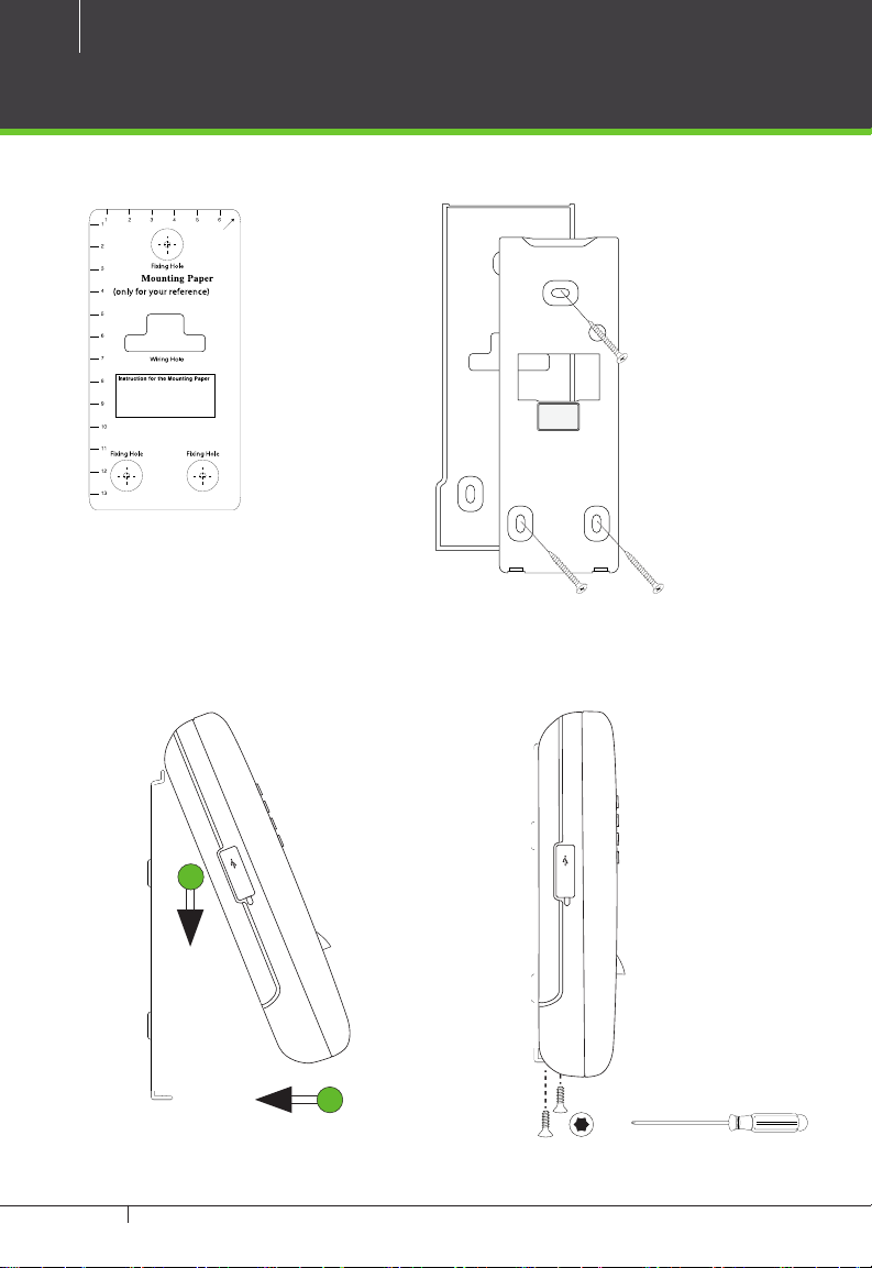
Mounting the reader on the wall
Fix back plate to the wall using wall mounting screws
1. Stick the mounting
template on the wall
and make holes as
per the markings.
2. Mount the rubber gasket
and the back plate on the
wall with the help of the
supplied screws.
We recommend drilling the mounting plate screws into solid wood (i.e. stud/beam). If a stud/beam
cannot be found, then use the supplied drywall plastic mollies (anchors).
1
Reset
2
4. Use star-shaped screw to mount it3. Inserting Reader to backplate
TF1700 & ZKAccess CLASSIC 3.5 software INSTALLATION GUIDE
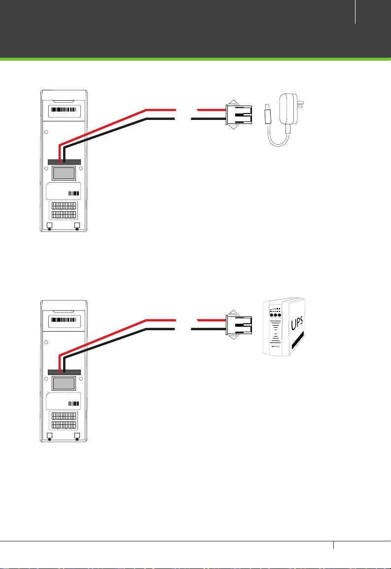
Power Connection
11
Without UPS
SN 000000000000
Fingerprint Access Control
Manufacturing license No: 75569364-2
SBTS Registered No: H0201
Power Supply DC 12V == 3A
Operating Environment Temperature: 0ºC-45ºC
2008 CE FC RoHS
ISO9000 :
SEN
NO1
BUT
GND
BELL-
BELL+
Blue
Gray
Black
White
Purple
Brown
Bell LOCK Alarm Ethernet
GND
+12V
RLED
GLED
IWD1
IWD0
Red
Blue
Gray
Black
Green
White
12V DC
GND
12V DC Adaptor
69370226
NO2
YNC1
COM2
COM1
RJ45-1
RJ45-2
RJ45-3
RJ45-6
:::
:
Red
Green
Yellow
Orange
485-
485+
GND
GND
WD0
WD1
+12V
BEEP
Red
Blue
Black
Black
Green
White
Yellow
Purple
Power485WG-OutReader
With UPS (Optional)
12V DC
GND
12V DC Adaptor
69370226
NO2
YNC1
COM2
COM1
RJ45-1
RJ45-2
RJ45-3
RJ45-6
:::
:
Red
Green
Yellow
Orange
485-
485+
GND
GND
WD0
WD1
+12V
BEEP
Red
Blue
Black
Black
Green
White
Yellow
Purple
Power485WG-OutReader
Recommended power supply
•Regulated 12V DC, 1A.
•Comply with standard IEC/EN 60950-1.
• To share the power with other devices, use a power supply with higher current ratings
TF1700 & ZKAccess CLASSIC 3.5 software INSTALLATION GUIDE
12
+
+
+
BUTTON BUTTONREADER 1 READER 2BUTTON BUTTONREADER 1 READER 2
RX
TX
RX
POWER
RUN CARD
485-
485+
IN
GND
BEEP
GLED
WD1
WD0
GND
+12V
BUTTON READER
IN
GND
BEEP
GLED
WD1
WD0
GND
+12V
BUTTON READER
IN
GND
BEEP
GLED
WD1
WD0
GND
+12V
BUTTON READER
NO
COM
NC
AUXOUT1
NO
COM
NC
AUXOUT2
NO
COM
NC
AUXOUT3
NO
COM
NC
V+V-12V
GND
AUXOUT4
SEN
GNDNOCOM
NC
LOCK1
SEN
GNDNOCOM
NC
LOCK2
SEN
GNDNOCOM
NC
LOCK3
SEN
GNDNOCOM
NC
LOCK4 LOCK POWER
IN
GND
BEEP
GLED
WD1
WD0
GND
+12V
BUTTON READER
+
+
+
BUTTON BUTTONREADER 1 READER 2BUTTON BUTTONREADER 1 READER 2
RX
TX
RX
POWER
RUN CARD
485-
485+
IN
GND
BEEP
GLED
WD1
WD0
GND
+12V
BUTTON READER
IN
GND
BEEP
GLED
WD1
WD0
GND
+12V
BUTTON READER
IN
GND
BEEP
GLED
WD1
WD0
GND
+12V
BUTTON READER
NO
COM
NC
AUXOUT1
NO
COM
NC
AUXOUT2
NO
COM
NC
AUXOUT3
NO
COM
NC
V+V-12V
GND
AUXOUT4
SEN
GNDNOCOM
NC
LOCK1
SEN
GNDNOCOM
NC
LOCK2
SEN
GNDNOCOM
NC
LOCK3
SEN
GNDNOCOM
NC
LOCK4 LOCK POWER
IN
GND
BEEP
GLED
WD1
WD0
GND
+12V
BUTTON READER
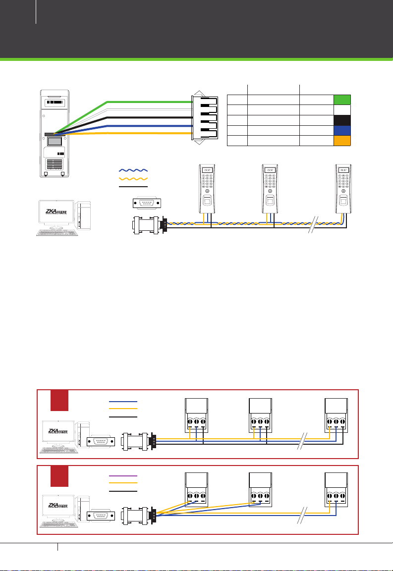
RS485 Connection
PC Connection
PIN DESCRIPTION WIRE
SN 000000000000
Fingerprint Access Control
Manufacturing license No: 75569364-2
SBTS Registered No: H0201
Power Supply DC 12V == 3A
Operating Environment Temperature: 0ºC-45ºC
69370226
2008 CE FC RoHS
ISO9000 :
SEN
NO2
NO1
BUT
GND
YNC1
BELL-
COM2
COM1
RJ45-1
RJ45-2
RJ45-3
RJ45-6
BELL+
:::
:
Red
Blue
Gray
Black
Green
White
Yellow
Purple
Brown
Orange
Bell LOCK Alarm Ethernet
485-
485+
GND
GND
GND
WD0
WD1
+12V
+12V
BEEP
RLED
GLED
IWD1
IWD0
Red
Red
Blue
Blue
Gray
Black
Black
Black
Green
Green
White
White
Yellow
Purple
Power485WG-OutReader
RS485 -RS485 +
GND
RS485
#1 TF1700 #2 TF1700 #63 TF1700
Important Notes:
1. RS485 communication wires should be a shielded and twisted pair cable.
2. RS485 communication wires should be connected in a bus cascade instead of
a star form, to achieve a better shielding eect by reducing signal reection
during communications.
3. Adjust the communication speed as needed. The signal quality vary depend-
ing on wiring conditions, and it maybe necessary to lower the baudrates.
4. The GND Signal may be omitted if and only if the GND potential dierence is
less than ±5V
Incorrect RS 485 connections
x
RS485 -RS485 +
GND
485+
485--
GND
PC
1 WD0 Red
2 WD1 White
3 GND Black
4 485+ Blue
5 485- Yellow
485+
485--
PC
GND
485+
485--
GND
PC
RS485
#1 TF1700
x
RS485 -RS485 +
GND
RS485
TF1700 & ZKAccess CLASSIC 3.5 software INSTALLATION GUIDE
#1TF1700
485+
485--
GND
PC
#2 TF1700
485+
485--
PC
#2 TF1700
GND
#63 TF1700
485+
485--
GND
PC
#63TF1700
SN 000000000000
Fingerprint Access Control
Manufacturing license No: 75569364-2
SBTS Registered No: H0201
Power Supply DC 12V == 3A
Operating Environment Temperature: 0ºC-45ºC
2008 CE FC RoHS
ISO9000 :
SEN
BUT
GND
BELL-
BELL+
Gray
Black
White
Purple
Brown
Bell LOCK Alarm Ethernet
GND
+12V
RLED
IWD1
IWD0
Red
Blue
Black
Green
White
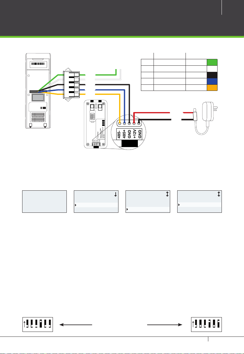
TF1700
13
FR1200 Connection
PIN DESCRIPTION WIRE
Weigand Out
WD0
WD1
GND
485+
485-
69370226
NO2
NO1
YNC1
COM2
COM1
RJ45-1
RJ45-2
RJ45-3
RJ45-6
:::
:
Red
Blue
Green
Yellow
Orange
485-
485+
GND
GND
WD0
WD1
+12V
BEEP
GLED
Red
Blue
Gray
Black
Black
Green
White
Yellow
Purple
Power485WG-OutReader
FR1200
TF1700 Settings
1 WD0 Red
2 WD1 White
3 GND Black
4 485+ Blue
5 485- Yellow
12V DC
GND
Welcome
13:04
15-01-21 WED
Menu
User Manage
Options
PenDrive Mng
Options Access Options
Power Mng
Comm Opt
Access Options
DSen. Mode NO
485ReaderMaster
MasterState Out
1. Steps to activate the master and salve functionality between TF1700 and
FR1200 as shown in the diagram on the left.
2. There are six DIP switches on the back of FR1200, Switches 1-4 is for RS485 ad-
dress , switch 5 is reserved , switch 6 is for reducing noise on long RS485 cable.
3. If FR1200 is powered from TF1700 terminal ,the length of wire should be less
than 100 meters or 330 ft.
4. If the cable length is more than 200 meters or 600 ft. , the number 6 switch
should be ON as below
5. 5.If the 485Reader set as Salve , it will be used as inBIO-series reader , check
page 28 to know more.
ON
123456
Distance: More than 200 meters
TF1700 & ZKAccess CLASSIC 3.5 software INSTALLATION GUIDE
ON
123456
14
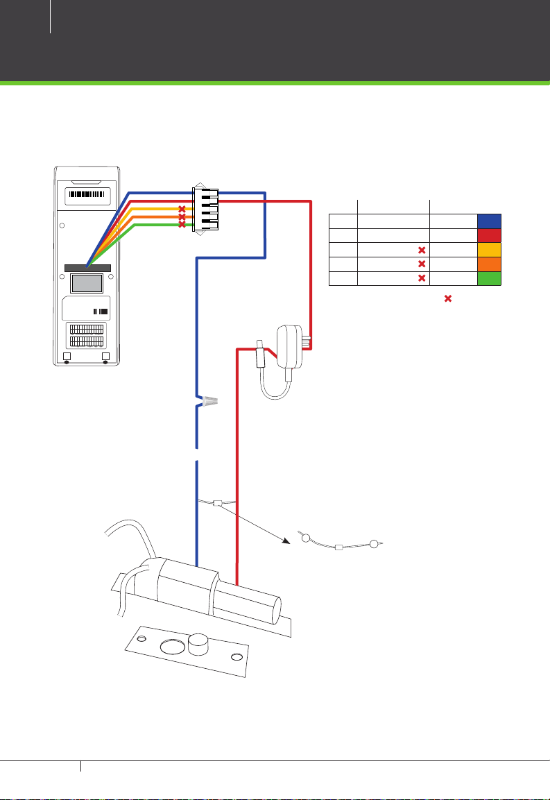
Lock Relay Connection
Normally Open Lock
SN 000000000000
Fingerprint Access Control
Manufacturing license No: 75569364-2
SBTS Registered No: H0201
Power Supply DC 12V == 3A
Operating Environment Temperature: 0ºC-45ºC
2008 CE FC RoHS
ISO9000 :
SEN
NO1
BUT
GND
BELL-
BELL+
Blue
Gray
Black
White
Purple
Brown
Bell LOCK Alarm Ethernet
GND
+12V
RLED
GLED
IWD1
IWD0
Red
Blue
Gray
Black
Green
White
PIN DESCRIPTION WIRE
1 NO1 Blue
2 COM1 Red
3 NC1 Yellow
4 NO2 Orange
5 COM2 Green
Do not use
69370226
NO2
YNC1
COM2
COM1
RJ45-1
RJ45-2
RJ45-3
RJ45-6
:::
:
Red
Green
Yellow
Orange
485-
485+
GND
GND
WD0
WD1
+12V
BEEP
Red
Blue
Black
Black
Green
White
Yellow
Purple
Power485WG-OutReader
12VDC
NO
-
FR107
Diode
+
TF1700 & ZKAccess CLASSIC 3.5 software INSTALLATION GUIDE
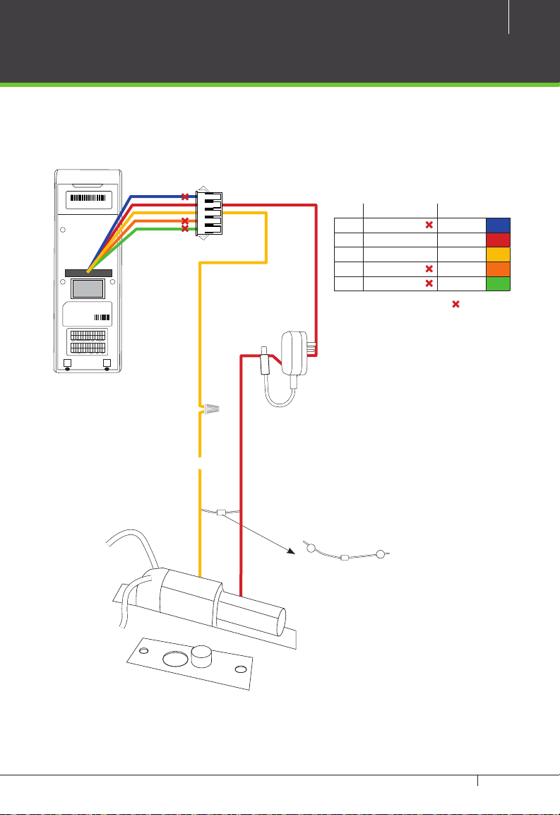
Normally Closed Lock
15
SN 000000000000
Fingerprint Access Control
Manufacturing license No: 75569364-2
SBTS Registered No: H0201
Power Supply DC 12V == 3A
Operating Environment Temperature: 0ºC-45ºC
2008 CE FC RoHS
ISO9000 :
SEN
NO1
BUT
GND
BELL-
BELL+
Blue
Gray
Black
White
Purple
Brown
Bell LOCK Alarm Ethernet
GND
+12V
RLED
GLED
IWD1
IWD0
Red
Blue
Gray
Black
Green
White
PIN DESCRIPTION WIRE
1 NO1 Blue
2 COM1 Red
3 NC1 Yellow
4 NO2 Orange
5 COM2 Green
Do not use
69370226
NO2
YNC1
COM2
COM1
RJ45-1
RJ45-2
RJ45-3
RJ45-6
:::
:
Red
Green
Yellow
Orange
485-
485+
GND
GND
WD0
WD1
+12V
BEEP
Red
Blue
Black
Black
Green
White
Yellow
Purple
Power485WG-OutReader
12VDC
NC1
-
FR107
Diode
+
TF1700 & ZKAccess CLASSIC 3.5 software INSTALLATION GUIDE
 Loading...